Shelf Systems With Adhesive Supports
Kokenge; John
U.S. patent application number 16/745829 was filed with the patent office on 2020-08-20 for shelf systems with adhesive supports. This patent application is currently assigned to Organized Living, Inc.. The applicant listed for this patent is Organized Living, Inc.. Invention is credited to John Kokenge.
| Application Number | 20200260870 16/745829 |
| Document ID | 20200260870 / US20200260870 |
| Family ID | 1000004610689 |
| Filed Date | 2020-08-20 |
| Patent Application | download [pdf] |


| United States Patent Application | 20200260870 |
| Kind Code | A1 |
| Kokenge; John | August 20, 2020 |
SHELF SYSTEMS WITH ADHESIVE SUPPORTS
Abstract
A method of assembling a shelf system includes positioning a shelf end bracket on a support surface. The shelf end bracket is mounted to the support surface. A shelf is located on the shelf support surface with the adhesive located therebetween.
| Inventors: | Kokenge; John; (Cincinnati, OH) | ||||||||||
| Applicant: |
|
||||||||||
|---|---|---|---|---|---|---|---|---|---|---|---|
| Assignee: | Organized Living, Inc. Cincinnati OH |
||||||||||
| Family ID: | 1000004610689 | ||||||||||
| Appl. No.: | 16/745829 | ||||||||||
| Filed: | January 17, 2020 |
Related U.S. Patent Documents
| Application Number | Filing Date | Patent Number | ||
|---|---|---|---|---|
| 62806266 | Feb 15, 2019 | |||
| Current U.S. Class: | 1/1 |
| Current CPC Class: | A47G 25/0692 20130101; A47B 47/042 20130101; A47B 96/06 20130101; A47B 96/024 20130101; A47B 96/021 20130101 |
| International Class: | A47B 96/02 20060101 A47B096/02; A47B 96/06 20060101 A47B096/06; A47B 47/04 20060101 A47B047/04; A47G 25/06 20060101 A47G025/06 |
Claims
1. A method of assembling a shelf system, the method comprising: positioning a shelf end bracket on a support surface; mounting the shelf end bracket to the support surface; and locating a shelf on the shelf support surface with an adhesive material located therebetween.
2. The method of claim 1 further comprising adjusting a position of the shelf on the shelf support surface before the adhesive gels.
3. The method of claim 2, wherein the adhesive material is configured to have a working time of greater than three minutes and less than five minutes.
4. The method of claim 1 further comprising applying a double-sided tape comprising the adhesive material to the shelf support surface.
5. The method of claim 1 further comprising positioning a shelf support brace on another support surface and mounting the shelf support brace to the another support surface.
6. The method of claim 5 further comprising removing a release liner to expose an adhesive material on the another support surface of the shelf support brace.
7. The method of claim 6, wherein the shelf support brace comprises a rod hanging structure configured to hold a rod.
8. The method of claim 1 further comprising removing a release liner to expose the adhesive material.
9. The method of claim 1, wherein the shelf comprises at least one of a fibreboard, a hollow core board and a honeycomb board.
8. A shelf system comprising: a shelf end bracket comprising: a shelf support surface; an adhesive material located on the shelf support surface, the shelf end bracket configured to mount to a support surface; and a release liner that covers the adhesive material; a shelf support brace comprising: another shelf support surface; another adhesive material located on the another shelf support surface, the shelf support brace configured to mount to a support surface; and another release liner that covers the another adhesive material.
9. The shelf system of claim 8, wherein the shelf support brace comprises a rod hanging structure configured to hold a rod.
10. The shelf system of claim 8, wherein the adhesive material is provided by a double-sided tape.
11. The shelf system of claim 8 further comprising a shelf configured to rest on the adhesive material.
12. The shelf system of claim 11, wherein the shelf comprises at least one of a fibreboard, a hollow core board and a honeycomb board.
13. The shelf system of claim 8, wherein the shelf end bracket and the shelf support brace comprise non-circular fastener openings.
14. A kit for a shelf system, comprising: a shelf end bracket comprising a shelf support surface, the shelf end bracket configured to mount to a support surface; a shelf support brace comprising another shelf support surface, the shelf support brace configured to mount to a support surface; an adhesive material that is no greater in area than the support surface of one or both of the shelf end bracket and the shelf support brace; and a container containing the shelf end bracket, the shelf support brace and the adhesive material.
15. The kit of claim 14 further comprising a shelf located in the package.
16. The kit of claim 15, wherein the shelf comprises at least one of a fibreboard, a hollow core board and a honeycomb board.
17. The kit of claim 14 comprising a double-sided tape comprising the adhesive material.
18. The kit of claim 17, wherein the double-sided tape is adhered to the support surface of one or both the shelf end bracket and the shelf support brace within the container, the double-sided tape comprising a release liner.
19. The kit of claim 17, wherein the double-sided tape is separate from the support surface of one or both the shelf end bracket and the shelf support brace insider the container, the double-sided tape comprising a release liner.
20. The kit of claim 14, wherein the shelf support brace comprises a rod hanging structure configured to hold a rod.
Description
CROSS-REFERENCE
[0001] This application claims the benefit of and priority to U.S. Provisional Patent Application No. 62/806,266, filed Feb. 15, 2019, the contents of which are hereby incorporated by reference.
TECHNICAL FIELD
[0002] The present specification generally relates to shelf systems and, more specifically, to wood shelf systems with supports that utilize an adhesive to support wood shelving.
BACKGROUND
[0003] Typical wood shelving systems utilize a combination of marking and drilling in order to install shelving supports and the shelves themselves to the shelving supports. Fasteners are used to mount the supports and also to connect the shelves to the supports. Problems can arise when the fasteners and holes are improperly placed, even a minor amount. This can require removal of the fasteners and re-drilling, which leaves holes in the wall to which the shelves were being mounted. Further, installers may drill the fasteners completely through the shelves causing the installer to scrap the shelves. Screws tend to strip out easily which requires the use of boards that are high density and therefore have greater screw holding ability. These boards are relatively expensive and heavy. The use of self-tapping wood screws can be difficult to get started to penetrate the relatively hard boards especially due to the inverted position of the installer when fastening the shelf to the brackets. Fasteners can also be unsightly on the bottoms of the shelves, which can be in direct of a home owner when using the shelves.
[0004] Accordingly, a need exists for a shelf system with supports that utilize an adhesive to connect the shelves to the supports. The adhesive can allow use of more economical, lower density wood boards for the shelving as fasteners are not needed to connect the shelves to their support brackets. The adhesive can also be forgiving in that it can take some time to cure, which can allow for repositioning of the shelves as the adhesive cures.
SUMMARY
[0005] In one embodiment, a method of assembling a shelf system includes positioning a shelf end bracket on a support surface. The shelf end bracket is mounted to the support surface. A release liner is removed to expose an adhesive material on a shelf support surface of the shelf end bracket. A shelf is located on the shelf support surface with the adhesive located therebetween.
[0006] In another embodiment, a shelf system includes a shelf end bracket including a shelf support surface. An adhesive material is located on the shelf support surface. The shelf end bracket is configured to mount to a support surface. A release liner overs the adhesive material. A shelf support brace includes another shelf support surface. Another adhesive material is located on the another shelf support surface. The shelf support brace is configured to mount to a support surface. Another release liner covers the another adhesive material.
[0007] In another embodiment, a kit for a shelf system includes a shelf end bracket including a shelf support surface. The shelf end bracket is configured to mount to a support surface. A shelf support brace includes another shelf support surface. The shelf support brace is configured to mount to a support surface. An adhesive material is provided that is no greater in area than the support surface of one or both of the shelf end bracket and the shelf support brace. A container contains the shelf end bracket, the shelf support brace and the adhesive material.
[0008] Additional features and advantages of the embodiments described herein will be set forth in the detailed description which follows, and in part will be readily apparent to those skilled in the art from that description or recognized by practicing the embodiments described herein, including the detailed description which follows, the claims, as well as the appended drawings.
[0009] It is to be understood that both the foregoing general description and the following detailed description describe various embodiments and are intended to provide an overview or framework for understanding the nature and character of the claimed subject matter. The accompanying drawings are included to provide a further understanding of the various embodiments, and are incorporated into and constitute a part of this specification. The drawings illustrate the various embodiments described herein, and together with the description serve to explain the principles and operations of the claimed subject matter.
BRIEF DESCRIPTION OF THE DRAWINGS
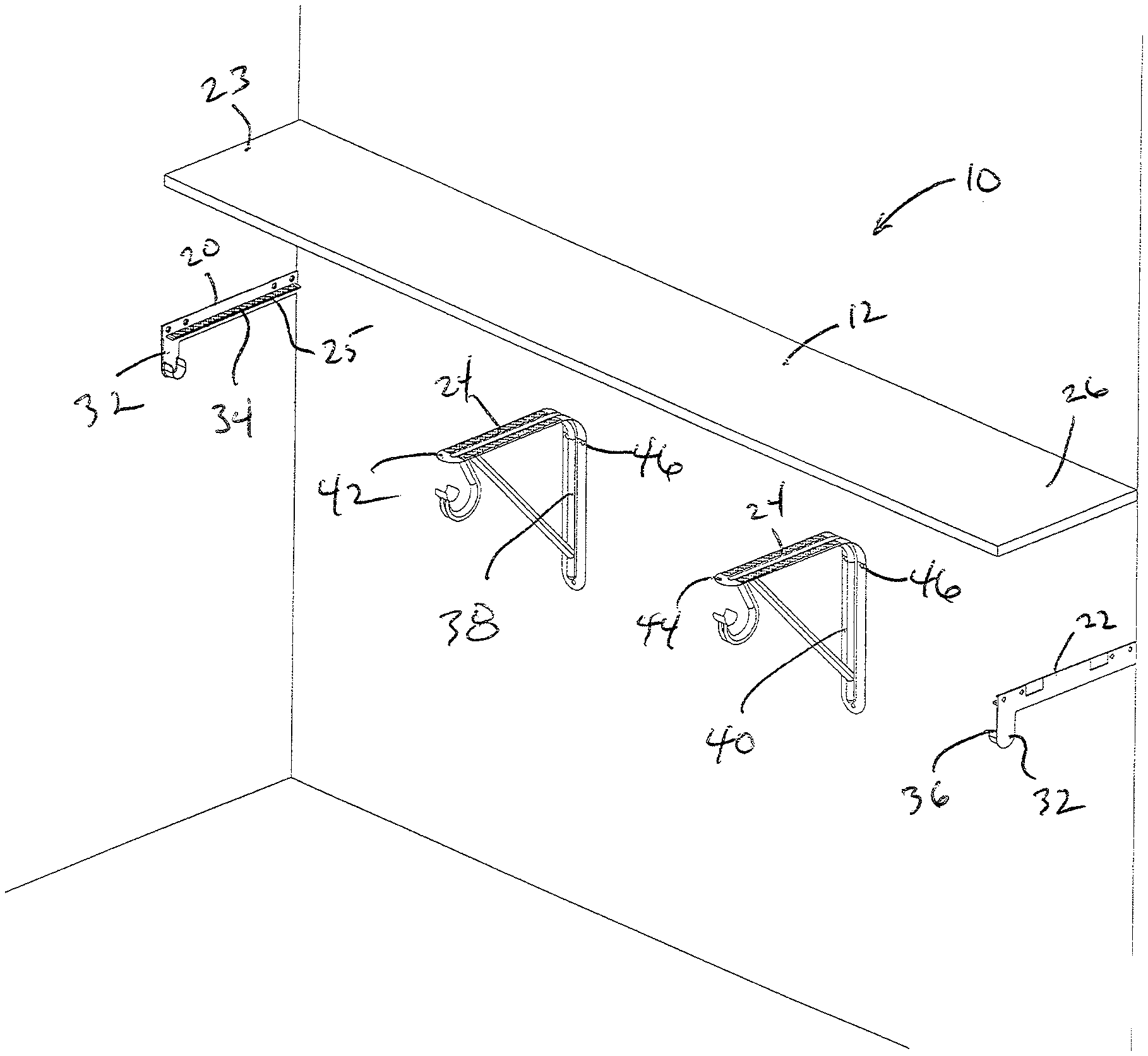
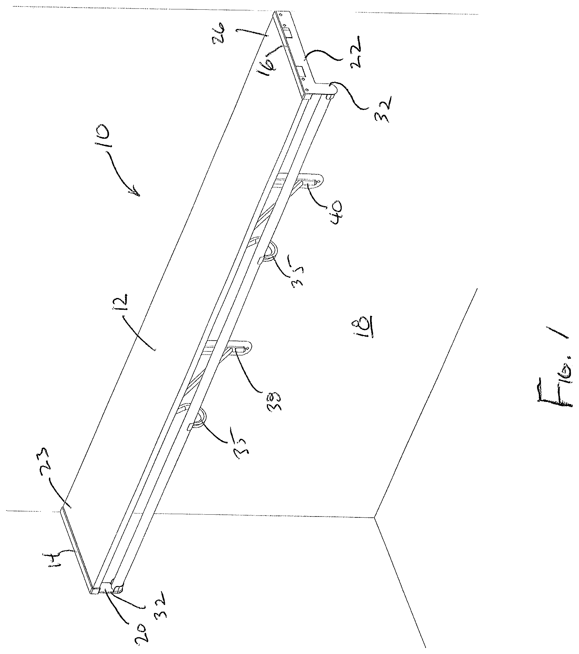
[0010] FIG. 1 depicts a perspective view of a shelf system, according to one or more embodiments shown and described herein;
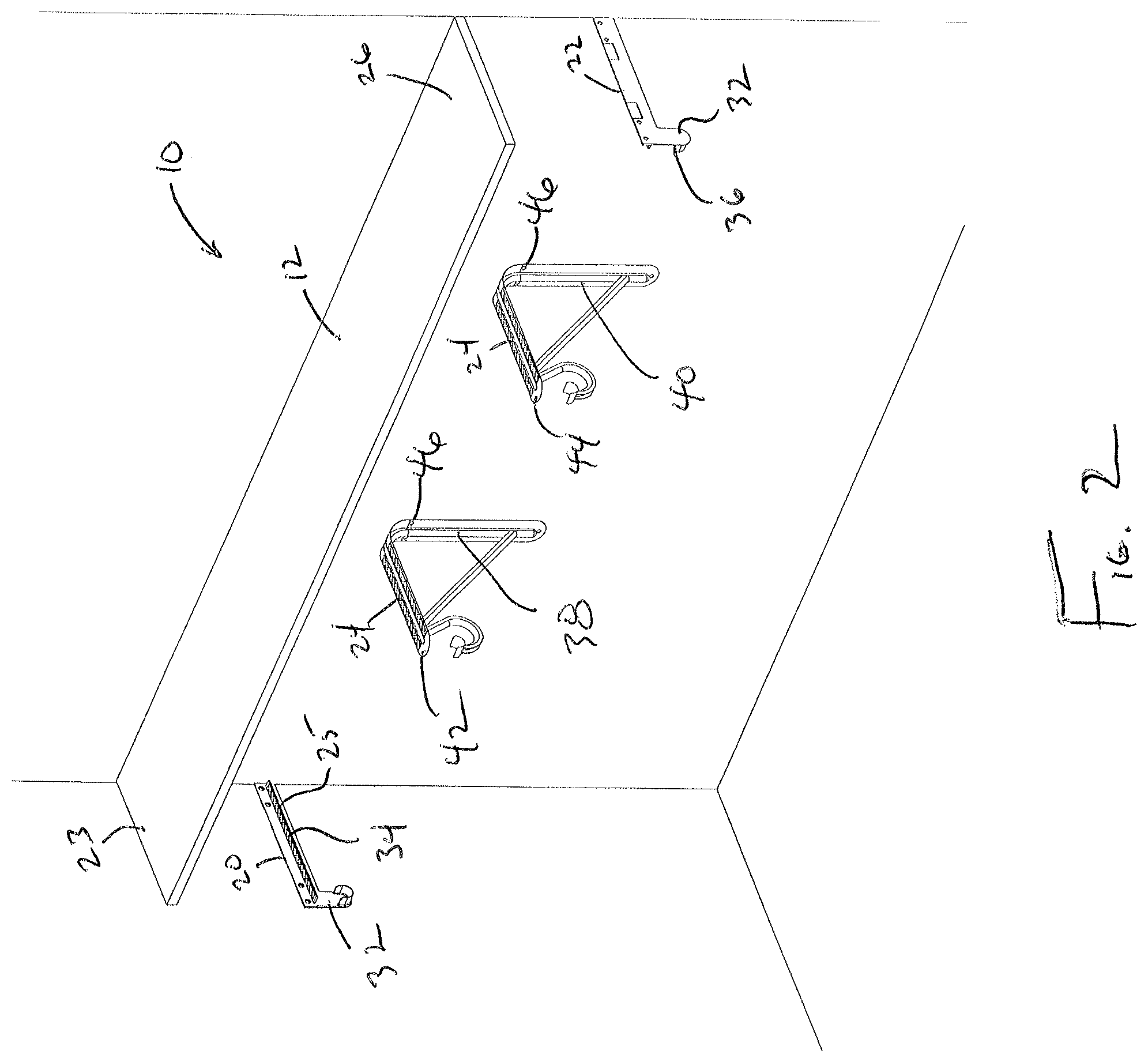
[0011] FIG. 2 depicts a perspective exploded view of the shelf system of FIG. 1, according to one or more embodiments shown and described herein;
[0012] FIG. 3 depicts another exploded view of the shelf system of FIG. 1, according to one or more embodiments shown and described herein;
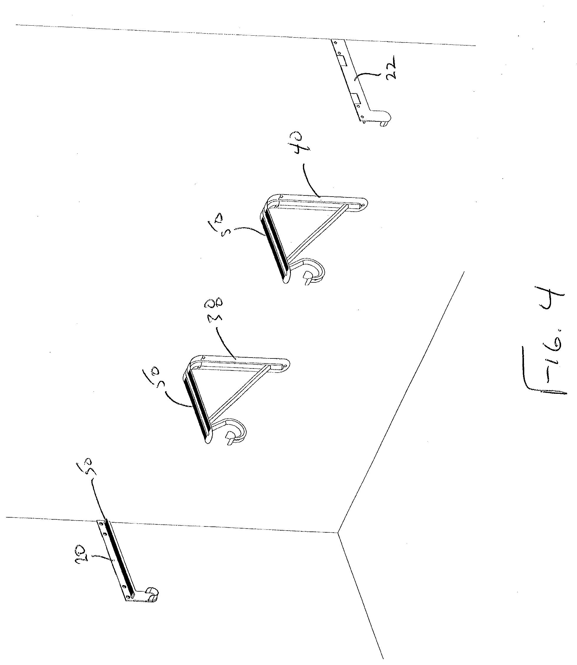
[0013] FIG. 4 depicts another perspective view of the shelf system of FIG. 1 with the shelf removed, according to one or more embodiments shown and described herein;
[0014] FIG. 5 depicts an assembled shelf system, according to one or more embodiments shown and described herein;
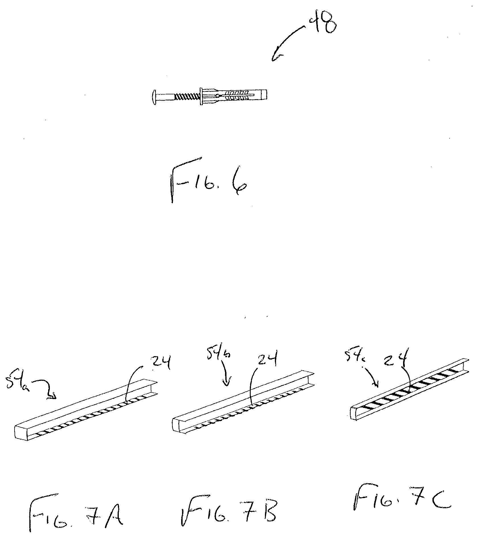
[0015] FIG. 6 depicts a perspective view of a non-circular anchor for use with the shelf system of FIG. 1, according to one or more embodiments shown and described herein;
[0016] FIG. 7A depicts an additional support structure for the shelf system, according to one or more embodiments shown and described herein;
[0017] FIG. 7B depicts another additional support structure for the shelf system, according to one or more embodiments shown and described herein;
[0018] FIG. 7C depicts another additional support structure for the shelf system, according to one or more embodiments shown and described herein; and
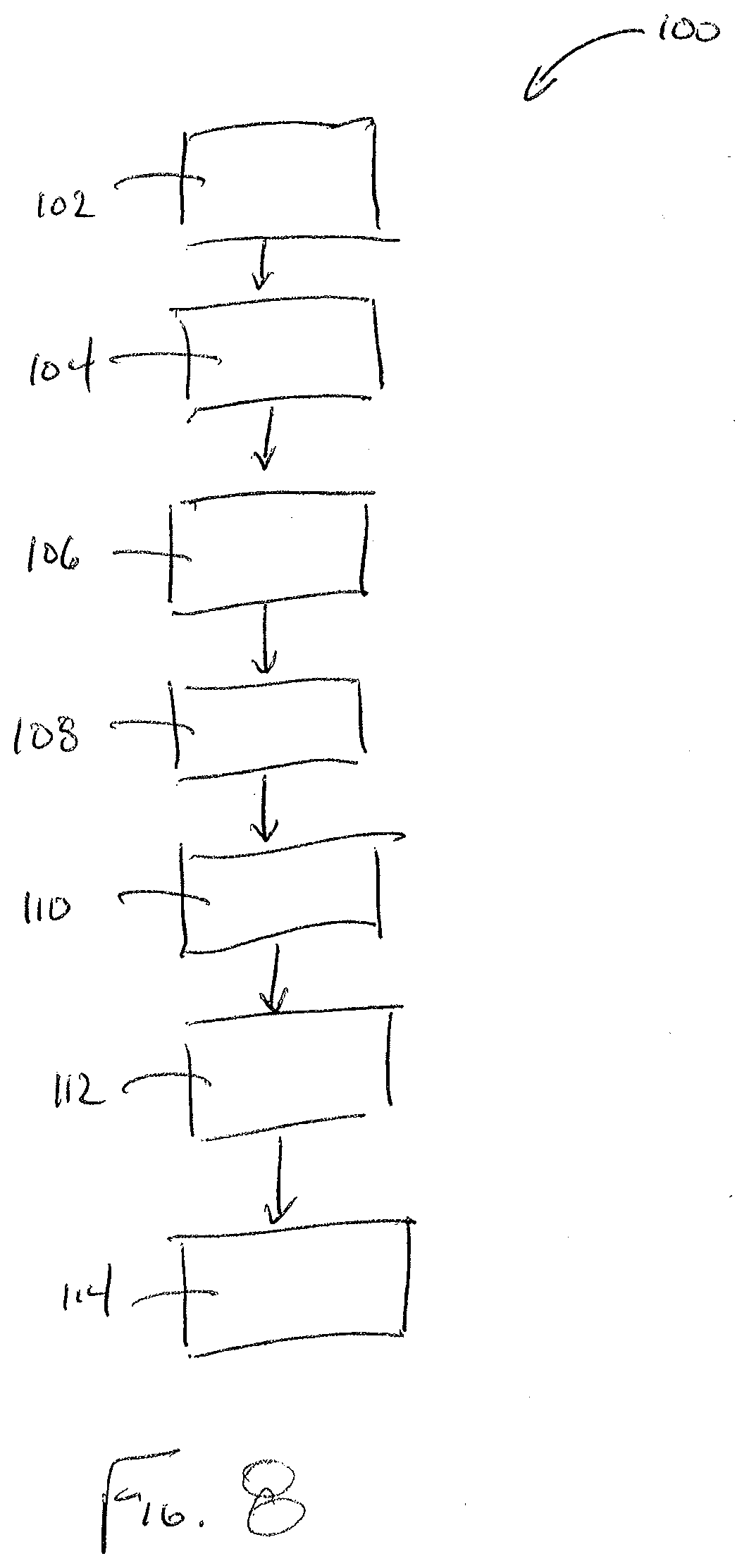
[0019] FIG. 8 depicts a method of assembling the shelf system of FIG. 1, according to one or more embodiments shown and described herein.
DETAILED DESCRIPTION
[0020] Embodiments described herein are directed to shelf systems that include planar, solid shelves (e.g., formed of wood) that are supported by support brackets that are fastened to a support surface, such as a wall. An adhesive is placed on a shelf support surface of the support brackets. The adhesive may have a reasonable working time (e.g., between about three and about five minutes) to allow for adjustment and readjustment of a shelf placed on the shelf support surface during the installation process. As used herein, "working time" is how much time the adhesive can be worked with before the material reaches such a high state of viscosity that the material cannot be properly worked with to produce an acceptable shelf location of the shelf support surface. "Working time" may be determined after running cure tests on the shelf system to determine what is the point when the adhesive material gels and how fast the viscosity increases to this gel state in the final stage of curing. "Gel time" is the time it takes for an adhesive to gel or become so highly viscous that it can no longer be considered workable or able to be handled. Working life and gel time may be determined at room temperature with a predetermined volume of adhesive material used to bond two parts together. In other embodiments, an adhesive having a faster working time may be used.
[0021] Referring to FIGS. 1-3, a shelf system 10 includes a solid, planar shelf 12 that may be formed of wood, shelf end bracket covers 14 and 16 that can be used to cover ends 23 and 26 of the shelf 12 and end brackets 20 and 22 that are used to connect the shelf 12 to a wall 18. Referring to FIG. 2, the end brackets 20 and 22 may be provided with an adhesive material 24 shown by hatching on one or more of their shelf support surfaces that receive the ends 23 and 26 of the shelf 12. The adhesive material 24 may have a reasonable working time of between about three and about five minutes to allow for adjustment and readjustment of a shelf placed on the shelf support surface during the installation process. For example, the adhesive material 24 may have a working time of less than five minutes.
[0022] The shelf system 10 may further include the end brackets 20 and 22 with a rod hanging structure 32. Shelf support surfaces 34 and 36 may be provided with the adhesive material 24. Shelf support braces 38 and 40 may also be used that include the adhesive material 24 on their shelf support surfaces 42 and 44. The shelf support braces 38 and 40 also include a rod hanging structure 35. In some embodiments, a support brace cover may be used to cover the support braces 38 and 40 when no shelf is being supported. The shelf support braces 38 and 40 and any of the other components may include non-circular openings 46 (e.g., trapezoidal) that can receive a cooperating non-circular wall anchor 48 (FIG. 6) to inhibit rotation of the wall anchor 48 as a fastener is drilled therethrough and the wall anchor 48 located within the opening 46.
[0023] Referring to FIG. 4, in some embodiments, the adhesive material 24 may be provided by a double-sided tape that includes a carrier material with opposite sides being covered by the adhesive material 24. A release liner 50 may be used to cover one or both sides of the double-sided tape, which may be removed before applying the shelf 12.
[0024] An example of an assembled shelf system is shown by element 52 of FIG. 5 and includes many of the components shown by FIGS. 1-4 and described above. In some embodiments, the components of the shelf system 10 may be supplied as a kit for assembly that is packaged together in a container with instructions in packaging, such as one or more boxes and/or bags. The adhesive material 24 may be packaged separately from the other components or pre-applied to the components with the release liner 50 or pre-applied with no release liner and the adhesive exposed. FIGS. 7A-7C illustrate C-shaped end support brackets 54a, 54b and 54c with adhesive material 24 that are sized to receive an end of a shelf.
[0025] Referring to FIG. 8, a method 100 of assembling the shelf system 10 is illustrated. The method 100 includes positioning a shelf end bracket against a wall at step 102. The shelf end bracket is affixed to the wall using a wall anchor and fastener at step 104. At step 106, a shelf support brace is positioned on another wall. The shelf support brace is affixed to the another wall using a wall anchor and a fastener at step 108. The steps 102, 104 and 106 may be repeated as needed. At step 112, a release liner may be removed to expose an adhesive material on the shelf support surfaces of the shelf end bracket and the shelf support brace. In some embodiments, a double-sided tape is applied to the shelf support surfaces before the release liner is removed at step 110. A shelf is then placed on the shelf support surfaces with the adhesive material located between the shelf support surfaces and the shelf at step 114.
[0026] The above-described shelf systems allow for relatively simple installation of shelving compared to traditional fastener shelf systems. A more economical lighter density board (e.g., fiberboard) can be used that has sufficient beam strength but low screw holding strength can be used with the adhesive material. Hollow core or honeycomb board can also be used that are significantly lighter than traditional shelves, which can be less weight for the installer and less weight on the wall and have little or no screw holding strength. The shelf system may be templated in that a template may be used to identify drilling locations in a wall for the support brackets. Further, installation may be simplified in that fasteners need not be threaded through the shelves due to the adhesive, which can be time-consuming.
[0027] It will be apparent to those skilled in the art that various modifications and variations can be made to the embodiments described herein without departing from the spirit and scope of the claimed subject matter. Thus it is intended that the specification cover the modifications and variations of the various embodiments described herein provided such modification and variations come within the scope of the appended claims and their equivalents.
* * * * *
D00000
D00001
D00002
D00003
D00004
D00005
D00006
D00007
XML
uspto.report is an independent third-party trademark research tool that is not affiliated, endorsed, or sponsored by the United States Patent and Trademark Office (USPTO) or any other governmental organization. The information provided by uspto.report is based on publicly available data at the time of writing and is intended for informational purposes only.
While we strive to provide accurate and up-to-date information, we do not guarantee the accuracy, completeness, reliability, or suitability of the information displayed on this site. The use of this site is at your own risk. Any reliance you place on such information is therefore strictly at your own risk.
All official trademark data, including owner information, should be verified by visiting the official USPTO website at www.uspto.gov. This site is not intended to replace professional legal advice and should not be used as a substitute for consulting with a legal professional who is knowledgeable about trademark law.