Cosmetic Container
NONAKA; Kenji
U.S. patent application number 16/643235 was filed with the patent office on 2020-08-20 for cosmetic container. This patent application is currently assigned to KOSE Corporation. The applicant listed for this patent is KOSE Corporation. Invention is credited to Kenji NONAKA.
| Application Number | 20200260832 16/643235 |
| Document ID | 20200260832 / US20200260832 |
| Family ID | 1000004827565 |
| Filed Date | 2020-08-20 |
| Patent Application | download [pdf] |


| United States Patent Application | 20200260832 |
| Kind Code | A1 |
| NONAKA; Kenji | August 20, 2020 |
COSMETIC CONTAINER
Abstract
A cosmetic container including a container body having an aperture, an inner container attached to an inner side of the container body such that a space in which a cosmetic can be stored is formed between the inner container and the container body, an inner plug attached to an inner side of the inner container to form a dual structure together with the inner container and to be rotatable within a prescribed range relative to the inner container, the inner plug capable of storing an applicator therein, and a lid body capable of sealing an aperture of the inner plug, wherein cosmetic through holes are provided in portions of main bodies of the inner container and the inner plug, and the cosmetic through holes are opened and closed by changing of relative positions of the cosmetic through holes as the inner plug rotates.
| Inventors: | NONAKA; Kenji; (Ageo-shi, JP) | ||||||||||
| Applicant: |
|
||||||||||
|---|---|---|---|---|---|---|---|---|---|---|---|
| Assignee: | KOSE Corporation Chuo-ku JP |
||||||||||
| Family ID: | 1000004827565 | ||||||||||
| Appl. No.: | 16/643235 | ||||||||||
| Filed: | August 14, 2018 | ||||||||||
| PCT Filed: | August 14, 2018 | ||||||||||
| PCT NO: | PCT/JP2018/030298 | ||||||||||
| 371 Date: | February 28, 2020 |
| Current U.S. Class: | 1/1 |
| Current CPC Class: | A45D 33/003 20130101; A45D 33/006 20130101 |
| International Class: | A45D 33/00 20060101 A45D033/00 |
Foreign Application Data
| Date | Code | Application Number |
|---|---|---|
| Aug 30, 2017 | JP | 2017-165465 |
Claims
1. A cosmetic container comprising a container body having an aperture, an inner container attached to an inner side of the container body such that a space in which a cosmetic can be stored is formed between the inner container and the container body, an inner plug attached to an inner side of the inner container to form a dual structure together with the inner container and to be rotatable within a prescribed range relative to the inner container, the inner plug capable of storing an applicator therein, and a lid body capable of sealing an aperture of the inner plug, wherein cosmetic through holes are respectively provided in portions of main bodies of the inner container and the inner plug, and the cosmetic through hole is opened and closed by changing of relative positions of the cosmetic through holes as the inner plug rotates.
2. The cosmetic container according to claim 1, wherein an elastic mesh is attached to the cosmetic through hole of the inner container.
3. The cosmetic container according to claim 1, wherein the cosmetic through holes are formed on a curved surface.
4. The cosmetic container according to claim 1, wherein a guide groove is provided on an inner peripheral surface of the inner container, a protruding portion which can be inserted into the guide groove is provided on an outer peripheral surface of the main body of the inner plug, the protruding portion is formed to be movable within a range of the guide groove, and a rotation angle of the inner plug is restricted by the movable range of the protruding portion.
5. The cosmetic container according to claim 1, wherein the inner plug has a locking projection on an upper surface of a flange projecting outward from an upper end of the main body of the inner plug, the lid body has a locking projection which can be locked to the locking projection on a rear surface of a top wall of the lid body, the locking projections are formed to have heights and shapes such that the locking projections are locked to each other when the lid body is opened and closed and are released from each other when a force equal to or greater than a predetermined force is applied during opening and closing.
6. The cosmetic container according claim 1, wherein the applicator includes a shaft portion and an application portion provided at one end of the shaft portion, and the inner plug is formed to be capable of storing the application portion therein.
7. The cosmetic container according to claim 1, wherein the lid body has a threaded portion which can be screwed to a threaded portion provided on an outer peripheral surface of a peripheral wall that hangs down from an outer peripheral edge of the flange of the inner plug, a cylindrical portion is provided standing upright from a top surface of the lid body, and the shaft portion of the applicator can be stored in the cylindrical portion.
8. The cosmetic container according to claim 4, wherein the inner plug has a locking projection on an upper surface of a flange projecting outward from an upper end of the main body of the inner plug, the lid body has a locking projection which can be locked to the locking projection on a rear surface of a top wall of the lid body, the locking projections are formed to have heights and shapes such that the locking projections are locked to each other when the lid body is opened and closed and are released from each other when a force equal to or greater than a predetermined force is applied during opening and closing.
9. The cosmetic container according claim 4, wherein the applicator includes a shaft portion and an application portion provided at one end of the shaft portion, and the inner plug is formed to be capable of storing the application portion therein.
10. The cosmetic container according claim 5, wherein the applicator includes a shaft portion and an application portion provided at one end of the shaft portion, and the inner plug is formed to be capable of storing the application portion therein.
11. The cosmetic container according to claim 4, wherein the lid body has a threaded portion which can be screwed to a threaded portion provided on an outer peripheral surface of a peripheral wall that hangs down from an outer peripheral edge of the flange of the inner plug, a cylindrical portion is provided standing upright from a top surface of the lid body, and the shaft portion of the applicator can be stored in the cylindrical portion.
12. The cosmetic container according to claim 5, wherein the lid body has a threaded portion which can be screwed to a threaded portion provided on an outer peripheral surface of a peripheral wall that hangs down from an outer peripheral edge of the flange of the inner plug, a cylindrical portion is provided standing upright from a top surface of the lid body, and the shaft portion of the applicator can be stored in the cylindrical portion.
13. The cosmetic container according to claim 6, wherein the lid body has a threaded portion which can be screwed to a threaded portion provided on an outer peripheral surface of a peripheral wall that hangs down from an outer peripheral edge of the flange of the inner plug, a cylindrical portion is provided standing upright from a top surface of the lid body, and the shaft portion of the applicator can be stored in the cylindrical portion.
Description
TECHNICAL FIELD
[0001] The present invention relates to a cosmetic container, and more particularly, to a cosmetic container which prevents a cosmetic from adhering to an applicator stored in the container when not in use, is easy to control cosmetic application amount, and further prevents clogging of a mesh attached to a cosmetic through hole.
BACKGROUND ART
[0002] Conventionally, powder cosmetic containers are flat bottomed plate-type containers such as jars, and include containers having a structure in which an upper surface of a filled cosmetic is covered with a flat drop-lid-type inner lid having holes, and containers having a structure in which an elastic net is attached to an aperture portion of the container as the inner lid. It has been general to apply the cosmetic that has come out on the inner lid through the holes or net to a skin or the like using a disk-shaped puff.
[0003] In such a powder cosmetic container, especially at the beginning of use, the cosmetic gets excessively adhered to an applicator such as a puff and tends to fall or be scattered on the outer surface of the container or on hands, clothes, etc., to stain the container, hands, clothes, etc. On the other hand, during repeated use, the cosmetic is pressed down through the inner lid with the applicator many times, and the cosmetic is gradually caking (solidified), making it difficult for the cosmetic to adhere to the applicator and impossible to use until the end, or making it difficult to obtain a light touch feeling of use expected for powder cosmetics. A new powder cosmetic container free from such drawbacks has been desired.
[0004] Therefore, the applicant of the present application conducted various studies on improvement of the powder cosmetic container, and developed a powder cosmetic container in which a cylindrical body is installed in a container body, the cylindrical body is provided with a cosmetic through hole through which the powder cosmetic can pass, and an applicator can be stored in the cylindrical body (PTL 1).
[0005] Such a cosmetic container has an excellent effect in that, since the powder cosmetic in the container body is taken into the cylindrical body through the cosmetic through hole as needed and adheres to the applicator, the powder cosmetic can be applied by a light touch until the end without caking. However, the cosmetic container still has the following problem.
[0006] That is, in the cosmetic container, the cosmetic through hole of the cylindrical body attached to the container body is always open, and there is a possibility that the powder cosmetic in the container body may enter the cylindrical body even not in use.
[0007] For this reason, the cosmetic which entered the cylindrical body at the time when it was not in use adheres to the applicator. As a result, there are cases where the cosmetic more than necessary adheres to the applicator when in use, and it is difficult to control the cosmetic application amount.
[0008] In addition, powder cosmetics are often used for finishing after applying a liquid foundation, etc., and cosmetics on the face may be transferred to the applicator during use. When the applicator is stored in the cylindrical body as it is, the cosmetics adhering to the applicator are transferred to a mesh attached to the through hole and adhere to the mesh, which may cause clogging. As a result, the cosmetic is hindered from passing through and cannot be taken into the cylindrical body, which makes it impossible to use until the end, or making it difficult to obtain a light touch feeling of use expected for powder cosmetics.
CITATION LIST
Patent Literature
[0009] PTL 1: JP-A-11-290119
SUMMARY OF INVENTION
Technical Problem
[0010] Therefore, an object of the present invention is to overcome such drawbacks of the conventional powder cosmetic container and to provide a cosmetic container which allows applying a powder cosmetic with a light touch to the last remnant, prevents the cosmetic from adhering to an applicator when not in use, is easy to control cosmetic application amount, and further allows preventing clogging caused by the cosmetic adhering to a mesh of a cosmetic through hole.
Solution to Problem
[0011] The present invention solves the aforementioned problems, and is a cosmetic container including a container body having an aperture, an inner container attached to an inner side of the container body such that a space in which a cosmetic can be stored is formed between the inner container and the container body, an inner plug attached to an inner side of the inner container to form a dual structure together with the inner container and to be rotatable within a prescribed range relative to the inner container, the inner plug capable of storing an applicator therein, and a lid body capable of sealing an aperture of the inner plug, wherein cosmetic through holes are respectively provided in portions of main bodies of the inner container and the inner plug, and the cosmetic through holes are opened and closed by changing of relative positions of the cosmetic through holes as the inner plug rotates.
[0012] Further, the present invention is a cosmetic container where an elastic mesh is attached to the cosmetic through hole of the inner container.
[0013] Further, the present invention is a cosmetic container where the cosmetic through holes are formed on a curved surface.
[0014] Moreover, the present invention is a cosmetic container where both the inner plug and the lid body have locking projections, the locking projections are formed to have heights and shapes such that the locking projections are locked to each other when the lid body is opened and closed and are released from each other when a force equal to or greater than a predetermined force is applied during opening and closing.
Advantageous Effects of Invention
[0015] In the cosmetic container according to the present invention, the cosmetic through holes are opened and closed by changing of the relative positions of the cosmetic through holes of the inner container and the inner plug in accordance with a rotation of the inner plug. This prevents the cosmetic from entering the inner plug when not in use, and the cosmetic can be prevented from unintentionally adhering to the applicator, which makes it easy to control the cosmetic application amount when in use.
[0016] Further, in the cosmetic container according to the present invention in which a mesh is attached to the cosmetic through hole, there is no risk that the cosmetic adhering to the applicator during use would be transferred to the mesh when being stored, and clogging of the mesh can be prevented beforehand.
[0017] In addition, in the cosmetic container according to the present invention in which an elastic mesh is attached to the cosmetic through hole, as the inner plug rotates, an aperture edge of the cosmetic through hole of the inner plug moves to rub the mesh from an inner side, and thus the cosmetic adhering to the mesh can be scraped off and clogging of the mesh can be prevented.
[0018] Moreover, in the cosmetic container according to the present invention in which both the inner plug and the lid body have locking projections that can be locked to each other, the inner plug rotates interlockingly with opening and closing of the lid body, and thus it is possible to open and close the cosmetic through hole simply by opening and closing the lid body. As a result, it is possible to save time and labor for rotating the inner plug.
BRIEF DESCRIPTION OF DRAWINGS
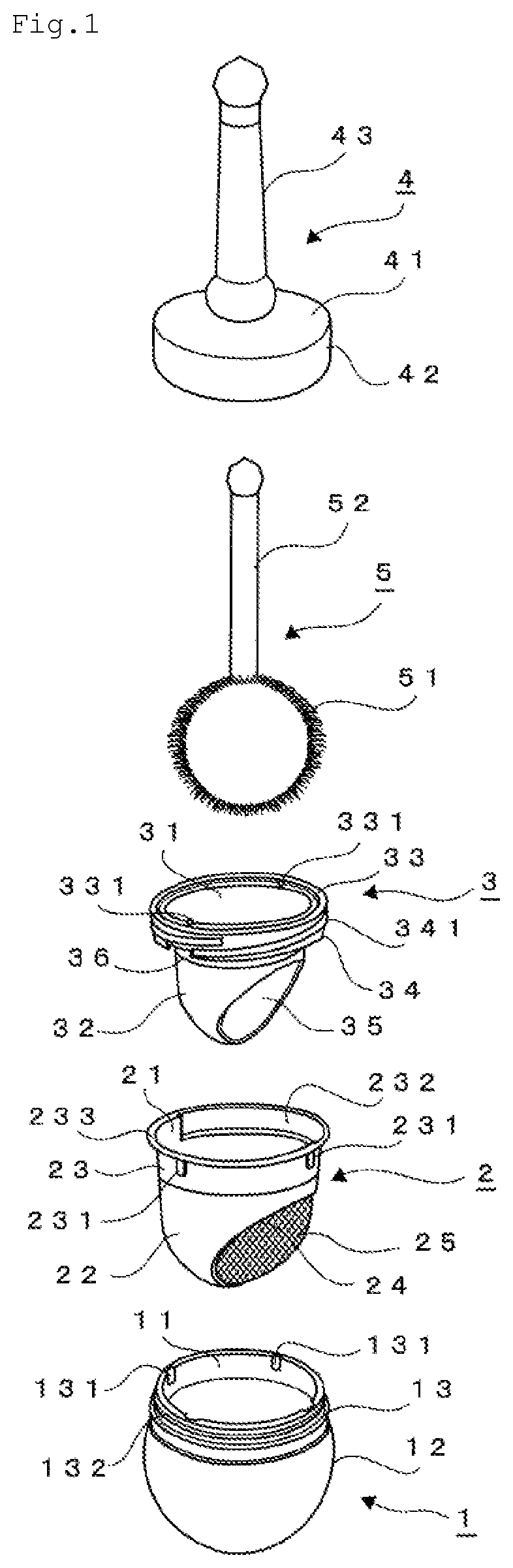
[0019] FIG. 1 is an exploded perspective view of a cosmetic container according to the present invention.
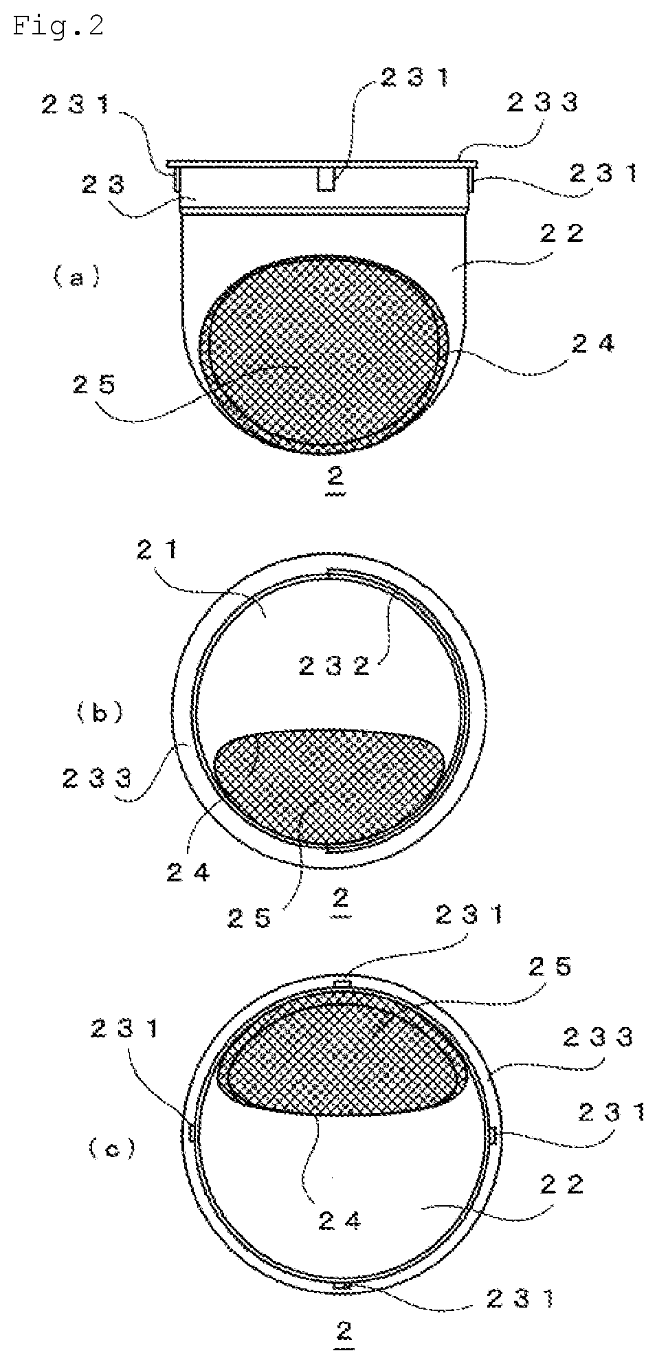
[0020] FIG. 2(a) is a front view of an inner container of the cosmetic container according to the present invention. FIG. 2(b) is a plan view of the inner container of the cosmetic container according to the present invention. FIG. 2 (c) is a bottom view of the inner container of the cosmetic container according to the present invention.
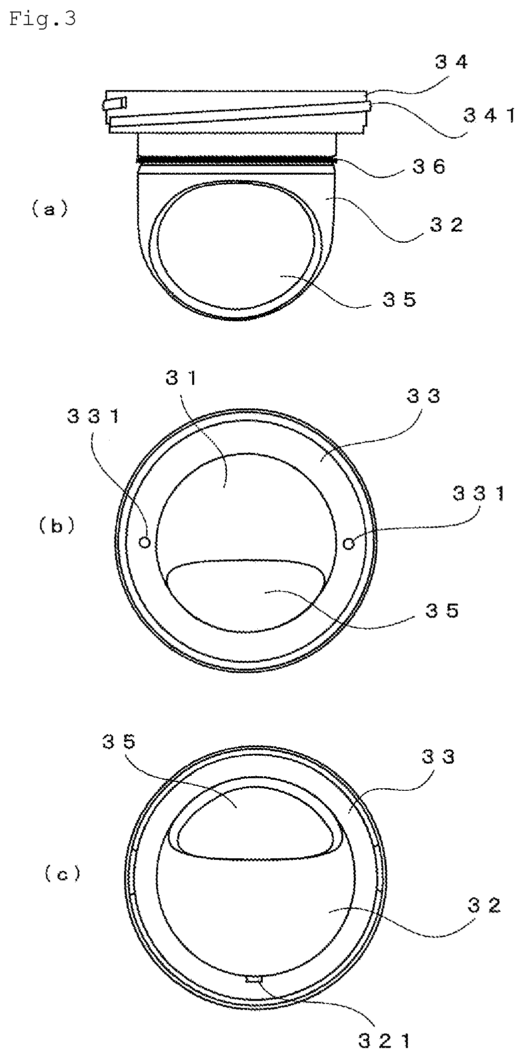
[0021] FIG. 3(a) is a front view of an inner plug of the cosmetic container according to the present invention. FIG. 3(b) is a plan view of the inner plug of the cosmetic container according to the present invention. FIG. 3(c) is a bottom view of the inner plug of the cosmetic container according to the present invention.
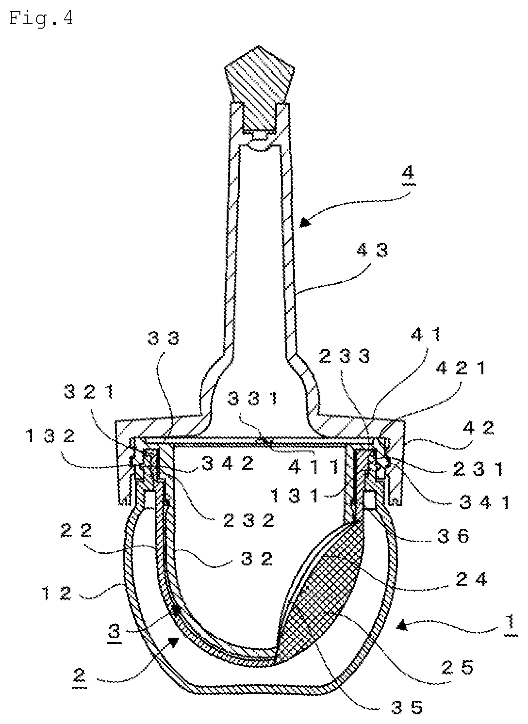
[0022] FIG. 4 is a cross-sectional view of the cosmetic container according to the present invention in an assembled state.
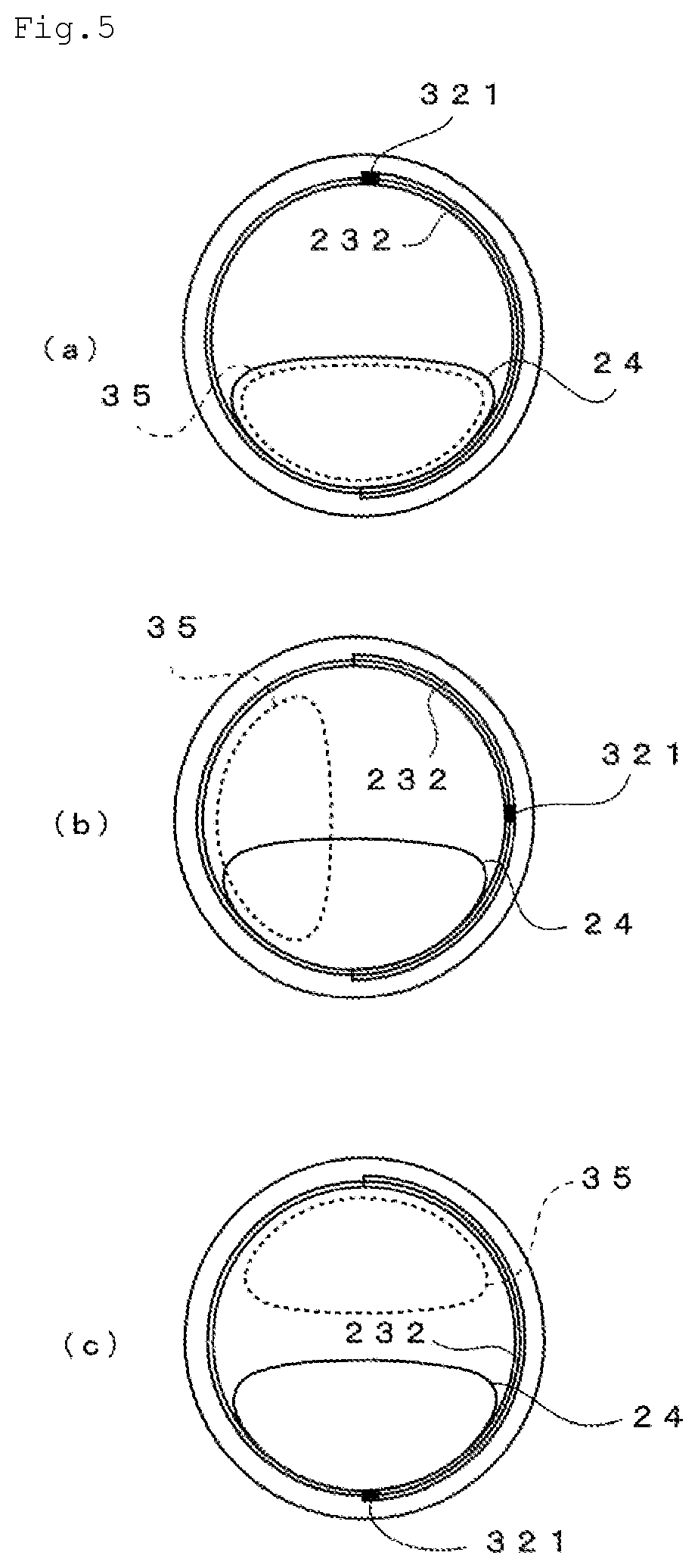
[0023] FIG. 5 is a schematic view showing a positional relation between a protruding portion 321 and a cosmetic through hole 24 and a cosmetic through hole 35 of the cosmetic container according to the present invention.
[0024] FIG. 6(a) is a schematic view showing a positional relation between a locking projection 331 and a locking projection 411 of the cosmetic container according to the present invention, and FIG. 6 (b) is a schematic view showing a positional relation between the locking projection 331 and the locking projection 411 of the cosmetic container according to the present invention.
[0025] FIG. 7 is a schematic view showing a mechanism which scrapes off a cosmetic adhering to a mesh of the inner container by an aperture edge of the inner plug according to the present invention.
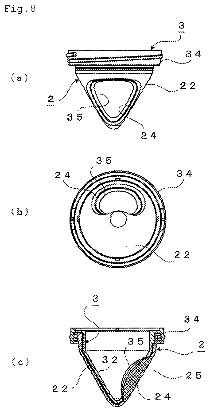
[0026] FIG. 8(a) is a front view of a cosmetic container according to a different embodiment of the present invention in a state in which an inner container and an inner plug are assembled. FIG. 8 (b) is a bottom view of the cosmetic container according to the different embodiment of the present invention in the state in which the inner container and the inner plug are assembled. FIG. 8(c) is a cross-sectional view of the cosmetic container according to the different embodiment of the present invention in the state in which the inner container and the inner plug are assembled.
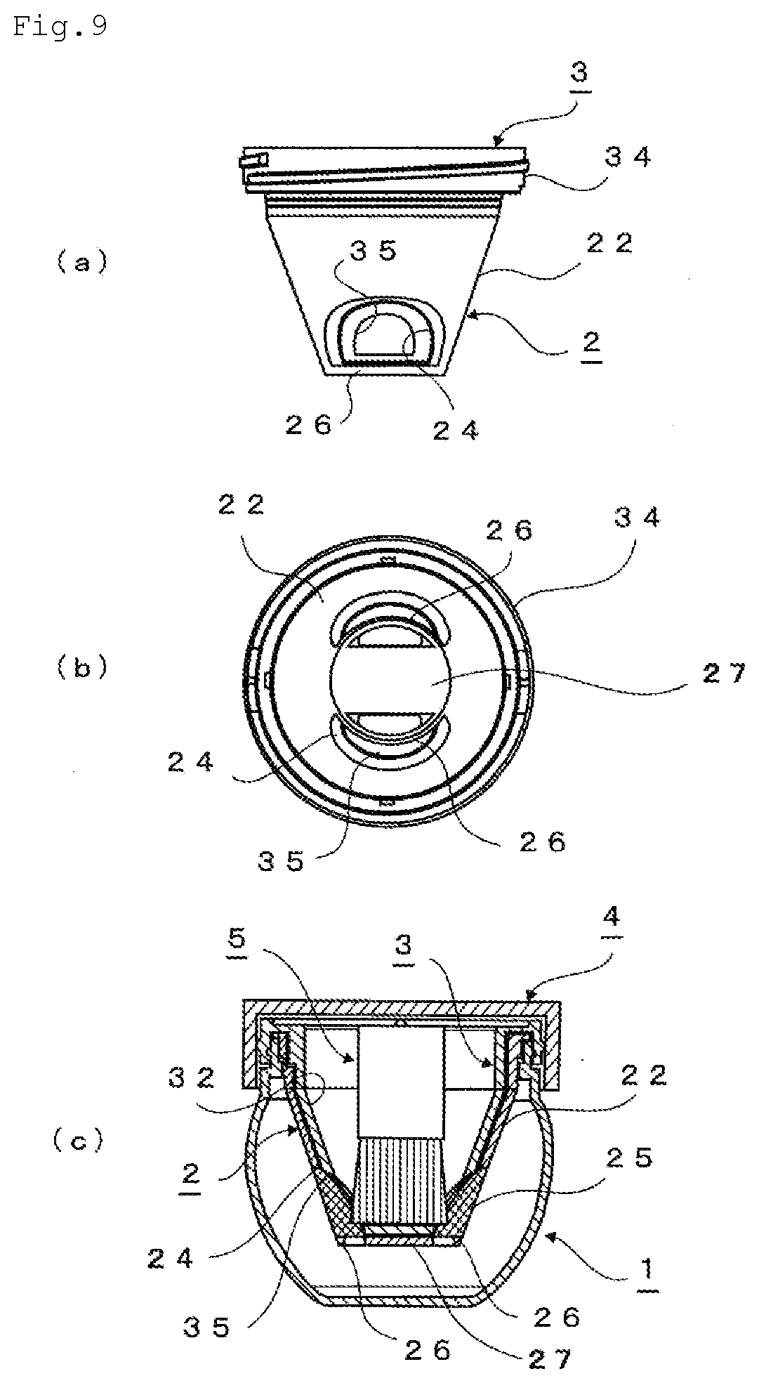
[0027] FIG. 9(a) is a front view of a cosmetic container according to a different embodiment of the present invention in a state in which an inner container and an inner plug are assembled. FIG. 9 (b) is a bottom view of the cosmetic container according to the different embodiment of the present invention in the state in which the inner container and the inner plug are assembled. FIG. 9(c) is a cross-sectional view showing a state in which the cosmetic container according to the embodiment is assembled and an applicator is stored in the cosmetic container.
DESCRIPTION OF EMBODIMENTS
[0028] Embodiments of the cosmetic container of the present invention will be described in detail below with reference to the drawings. The present invention is not limited to these embodiments.
[0029] The cosmetic container of the present invention includes a container body 1 having an aperture 11 at an upper portion of the container body 1, an inner container 2 attached to an inner side of the container body 1 such that a space in which a cosmetic can be stored is formed between the inner container 2 and the container body 1, an inner plug 3 attached to an inner side of the inner container 2 to form a dual structure together with the inner container 2 and to be rotatable within a prescribed range relative to the inner container 2, the inner plug 3 capable of storing an applicator 5 therein, and a lid body 4 capable of sealing an aperture 31 of the inner plug 3. Each member will be described in detail below.
[0030] The container body 1 is formed in a substantially pot shape having the aperture 11 at the upper portion of the container body 1, and includes a main body 12 in which a cosmetic is stored, and a neck portion 13 which is vertically provided annularly from an upper end of the main body 12. The main body 12 of the present embodiment has a larger diameter on the neck portion 13 side than on a bottom portion side, and further bulges out to have the largest diameter at an intermediate portion of the main body 12. However, the shape is not limited thereto as long as the container body 1 has the annularly shaped neck portion 13 at the upper portion and is capable of storing the cosmetic and the inner container 2 therein. For example, the container body 1 may be a cylindrical shape, a spherical shape, a polygonal columnar shape, a truncated cone shape, etc.
[0031] A recessed portion 131 is provided recessed in an inner peripheral surface of the neck portion 13 as a fixing unit of the inner container 2 which will be described later. The recessed portion 131 is provided to be in a substantially rectangular shape from an upper end of the neck portion 13 and thinner than the other portions of the neck portion 13. In the embodiment, four recessed portions 131 are provided at equal intervals in a circumferential direction of the neck portion 13. Although the number of the recessed portion 131 is arbitrary and may be one, it is preferable to provide a plurality of recessed portions 131.
[0032] Further, a protruded strip 132 is provided on an outer peripheral surface of the neck portion 13 as a locking unit of the inner plug 3 which will be described later. The protruded strip 132 protrudes annularly in the circumferential direction of the neck portion 13. The protruded strip 132 is provided at a position corresponding to a groove portion 342 of the inner plug 3 when the inner plug 3 is attached to the container body 1, and is formed in a shape that can be inserted into the groove portion 342.
[0033] As shown in FIG. 1 and FIG. 2, the inner container 2 has an aperture 21 at an upper portion of the inner container 2, and includes a main body 22 having a substantially cylindrical body portion and a substantially hemispherical bottom portion, and a neck portion 23 which is vertically provided annularly from an upper end of the main body 22. Further, a flange portion 233 which horizontally protrudes outward is provided on an upper end of the neck portion 23. The main body 22 is formed in a shape and with a dimension such that, when the main body 22 is attached to the container body 1, a space in which a cosmetic can be stored is formed between the main body 22 and the main body 12 of the container body 1, a main body 32 of the inner plug 3 can be stored therein, and the inner plug 3 is rotatable in the circumferential direction inside the main body 22. Specifically, at least the main body 22 forms a perfect circle in its horizontal cross-sectional shape, such as a spherical shape, a cylindrical shape, an inverted conical shape, and an inverted truncated cone shape. In addition, the neck portion 23 is formed such that the neck portion 13 of the container body 1 can be fitted therein.
[0034] The main body 22 is provided with a cosmetic through hole 24 for taking in the cosmetic in the container body 1 into the inner container 2. In the embodiment, one cosmetic through hole 24 is provided as a substantially circular aperture from one side surface (the front side in FIG. 2) to the bottom portion of the main body 22. Further, a mesh 25 may be attached to an edge portion of the cosmetic through hole 24 so as to close the aperture as in the embodiment.
[0035] In the embodiment, only one cosmetic through hole 24 is provided. However, the number is not limited thereto and a plurality of cosmetic through holes 24 may be provided. As to the position where the cosmetic through hole 24 is provided, it is not limited as long as it is a position where the cosmetic can be taken into the inner container 2 from the cosmetic through hole 24. When the main body 22 has a substantially spherical shape as in the embodiment, it is preferable to provide the cosmetic through hole 24 from a side surface to the bottom portion. When the main body 22 has a shallow plate shape, it is preferable to provide the cosmetic through hole 24 at the bottom surface. When the main body 22 has a conical shape, it is preferable to provide the cosmetic through hole 24 at the side surface. Further, when the cylindrical bottom surface is formed in a conical shape, it is preferable to provide the cosmetic through hole 24 at both the side surface and the bottom portion. In particular, it is preferable that the cosmetic through hole 24 is formed on a curved surface. For example, when the cosmetic through hole 24 is formed on a curved surface such as a side surface or a bottom portion of a substantially spherical main body, a side surface of an inverted conical or inverted truncated conical main body, and a side surface of a cylindrical main body, it is possible to obtain an effect of scraping the cosmetic adhering to the mesh 25 which will be described later and thus is preferable.
[0036] The shape and area of the cosmetic through hole 24 are not limited as long as the shape and area do not hinder the cosmetic from being taken into the inner container 2. However, as in the embodiment, when an application portion 51 of the applicator 5 to be used is a flocked spherical shape or a three-dimensional chip, it is possible to make the cosmetic adhere to the application portion 51 by pressing the application portion 51 against the mesh 25 and making the application portion 51 protrude from the cosmetic through hole 24 to an inner side of the container body 1 using the elasticity of the mesh 25. Therefore, it is preferable to form one cosmetic through hole 24 having an aperture diameter and an aperture shape through which the application portion 51 can pass. Further, when the application portion 51 is a flat mat or puff, it is not necessary to pass through the cosmetic through hole 24 to protrude to the inner side of the container body 1. Therefore, it is preferable to provide a plurality of through holes having a diameter smaller than that of the mat or puff.
[0037] In the embodiment, the mesh 25 is attached to the cosmetic through hole 24. However, the cosmetic through hole 24 itself may be formed in a mesh shape. That is, the cosmetic through hole 24 may be formed in a mesh shape by being composed of a collection of a plurality of fine holes, and in this case, the diameter of one hole is only necessary to be a diameter that the cosmetic can pass through. As described above, by attaching the mesh 25 to the cosmetic through hole 24, or by forming the cosmetic through hole 24 itself in a mesh shape, the cosmetic can be appropriately adhered to the application portion 51 at the time of use.
[0038] It is preferable that the material of the mesh 25 attached to the cosmetic through hole 24 has elasticity. For example, fibers such as polyester, polyurethane, nylon, rayon, polyolefin, cellulose, and silk, and mixed fibers thereof, or nonwoven fabrics thereof can be exemplified, and among them, mixed fibers of polyester and polyurethane are preferable.
[0039] In addition, a protruding portion 231 is provided protruding on an outer peripheral surface of the neck portion 23 as a fixing unit to the main body 1. The protruding portion 231 is provided at a position corresponding to the recessed portion 131 of the container body 1 when the inner container 2 is attached to the container body 1, and is formed in a substantially rectangular shape that can be inserted into the recessed portion 131. In the embodiment, four protruding portions 231 are provided at equal intervals in a circumferential direction of the neck portion 23. Although the number of the protruding portion 231 is arbitrary and may be one, it is preferable to provide a plurality of protruding portions 231 as the same number as the recessed portions 131.
[0040] Further, a guide groove 232 into which a protruding portion 321 of the inner plug 3 which will be described later can be inserted is formed on an inner peripheral surface of the neck portion 23. The guide groove 232 is formed at a predetermined height from the upper end of the neck portion 23 and to be thinner than the other portions of the neck portion 23, and is formed within a predetermined range in the circumferential direction of the neck portion 23. In the embodiment, the guide groove 232 is provided on the substantially right half of the inner peripheral surface of the neck portion 23. However, the providing position (circumferential direction) is arbitrary, and the providing range (circumferential direction) is desirably to be a range corresponding to a rotation range of the inner plug 3 from opening the cosmetic through hole 24 of the inner container 2 to closing the cosmetic through hole 24 of the inner container 2.
[0041] As shown in FIG. 1 and FIG. 3, the inner plug 3 has an aperture 31 at an upper portion of the inner plug 3, and includes a main body 32 having a substantially cylindrical body portion and a substantially hemispherical bottom portion, a flange 33 which horizontally protrudes outward from an upper end of the main body 32, and a peripheral wall 34 that hangs down from an outer peripheral edge of the flange 33. The main body 32 is formed in a shape substantially similar to the shape of the main body 22 so as to form a dual structure that does not form a gap more than necessary between the main body 32 and the main body 22 of the inner container 2 when the main body 32 is attached to the inner container 2, and is formed with a play to an extent that the main body 32 is rotatable in the circumferential direction in the attached state. The shape of the main body 32 is not limited as long as it is substantially similar to the shape of the main body 22 and is rotatable in the circumferential direction. However, at least the main body 32 forms a perfect circle in its horizontal cross-sectional shape, such as a spherical shape, a cylindrical shape, an inverted conical shape, and an inverted truncated cone shape.
[0042] The main body 32 is provided with a cosmetic through hole 35. The cosmetic through hole 35 is formed at a position corresponding to the cosmetic through hole 24 of the inner container 2 when the inner plug 3 is at an open position. In the embodiment, one cosmetic through hole 35 is provided as a substantially circular aperture from one side surface (the front side in FIG. 3) to the bottom portion of the main body 32.
[0043] In the embodiment, only one cosmetic through hole 35 is provided. However, the number is not limited thereto and a plurality of cosmetic through holes 35 may be provided. Further, the number of the cosmetic through holes 35 may be more or less than the number of the cosmetic through holes 24. However, it is preferable to provide the same number of the cosmetic through holes 35 as the number of the cosmetic through holes 24. The cosmetic through hole 35 is preferably provided with an area and in a shape substantially the same as the area and the shape of the cosmetic through hole 24 provided at a corresponding position. However, when a plurality of cosmetic through holes 24 are provided, it is also possible to provide one cosmetic through hole 35 that can cover the entire area where the plurality of cosmetic through holes 24 are provided. Conversely, when one cosmetic through hole 24 is provided as in the embodiment, a plurality of cosmetic through holes 35 may be provided in a region covered by the cosmetic through hole 24. Moreover, as in the embodiment, when the application portion 51 of the applicator 5 to be used is a flocked spherical shape or a three-dimensional chip, it is preferable to form one cosmetic through hole 35 having an aperture diameter through which the application portion 51 of the applicator 5 can pass. Further, it is preferable that the cosmetic through hole 35 is formed on a curved surface. For example, when the cosmetic through hole 35 is formed on a curved surface such as a side surface or a bottom portion of a substantially spherical main body, a side surface of an inverted conical or inverted truncated conical main body, and a side surface of a cylindrical main body, it is possible to obtain an effect of scraping the cosmetic adhering to the mesh 25 which will be described later and thus is preferable.
[0044] A threaded portion 341 to which a threaded portion 421 of the lid body 4 which will be described later can be screwed is provided on an outer peripheral surface of the peripheral wall 34, and the annular groove portion 342 into which the protruded strip 132 provided on the neck portion 13 of the container body 1 is provided recessed in an inner peripheral surface of the peripheral wall 34.
[0045] A locking projection 331 which can be locked to a locking projection 411 of the lid body 4 which will be described later is provided on an upper surface of the flange 33 in the inner plug 3 of the embodiment. In the embodiment, two locking projections 331 are provided at opposite positions of the flange 33 (right and left in FIG. 3(b)). The locking projections 331 are formed at a protruding height capable of locking with the locking projection 411 of the lid body 4 when the lid body 4 is opened and closed, and are formed in a shape such that the locking is released by applying a force equal to or greater than a predetermined force during opening and closing. The locking between the locking projection 331 and the locking projection 411 is released by applying a pressure equal to or more than a predetermined pressure to a side surface where the locking projection 331 and the locking projection 411 are in contact to make the locking projection 411 get over the locking projection 331. Therefore, the side surface of the locking projection 331 may be formed in a tapered shape so as to make the locking projection 411 easily get over the locking projection 331.
[0046] Moreover, an annular O-ring 36 may be attached to the outer peripheral surface of the main body 32 as in the embodiment. The O-ring is formed with an elastic member such as rubber, and slides on the inner peripheral surface of the main body 22 to generate an appropriate rotation resistance when the inner plug 3 is rotated in the inner container 2.
[0047] In addition, the protruding portion 321 which can be inserted into the guide groove 232 of the inner container 2 is provided protruding on the outer peripheral surface near the upper end portion of the main body 32. The protruding portion 321 is formed in a substantially rectangular shape extending downward from the flange 33, and is formed at a height that fits in the guide groove 232. Although one protruding portion 321 is provided on a rear surface side of the main body 32 in the embodiment, the position is not limited thereto.
[0048] The lid body 4 of the present invention is not particularly limited in its shape and attaching and detaching method as long as the lid body 4 can seal the aperture 31 of the inner plug 3. As in the embodiment, the lid body 4 may be screwed to the threaded portion 341 of the inner plug 3 and a part of the lid body 4 may have a space in which a part of the applicator 5 can be stored. In the lid body 4 of the embodiment, the threaded portion 421 is formed on an inner peripheral surface of a peripheral wall 42 hanging down from a peripheral edge of a top wall 41 so as to be capable of being screwed to the threaded portion 341 of the inner plug 3, and a shaft portion 52 of the applicator 5 which will be described later can be stored in a cylindrical portion 43 provided standing upright from the top wall 41.
[0049] In the lid body 4 of the embodiment, the locking projection 411 which can be locked to the locking projection 331 of the flange 33 of the inner plug 3 is provided on a rear surface of the top wall 41. The locking projection 411 is formed at a position where the locking projection 411 can be brought into contact with the locking projection 331 of the inner plug 3 when the lid body 4 is opened and closed. Moreover, the locking projection 411 is formed to have a height capable of locking with the locking projection 331, and is formed to have a height and a shape such that the locking is released by applying a force equal to or greater than a predetermined force during opening and closing. The locking between the locking projection 331 and the locking projection 411 is released by applying a pressure equal to or more than a predetermined pressure to a side surface where the locking projection 331 and the locking projection 411 are in contact to make the locking projection 411 get over the locking projection 331. Therefore, the side surface of the locking projection 411 may be formed in a tapered shape so as to make the locking projection 411 easily get over the locking projection 331.
[0050] The applicator 5 used in the cosmetic container of the present invention is not particularly limited in its type, shape, etc. As shown in FIG. 1, it is possible to use an applicator in which the application portion 51 is provided at a tip end of the shaft portion 52, or a puff type having an application portion only. Moreover, a sewed puff, a napped puff, a sponge, a brush, etc. can be used as the application portion 51.
[0051] FIG. 4 is a cross-sectional view of the cosmetic container of the present invention in an assembled state. As shown in the drawing, the inner container 2 is attached to the inner side of the container body 1. The inner container 2 is inserted from the aperture 11 of the container body 1, and the flange portion 233 of the inner container 2 is hooked on the upper end portion of the neck portion 13 of the container body 1. Moreover, the protruding portion 231 is inserted into the recessed portion 131 of the container body 1. In this way, the inner container 2 is attached to the container body 1 in a state in which the rotation of the inner container 2 relative to the container body 1 is restricted.
[0052] Further, the inner plug 3 is attached to the inner side of the inner container 2. The inner plug 3 is inserted from the aperture 21 of the inner container 2, and the flange 33 of the inner plug 3 is placed on the flange portion 233 of the inner container 2. Moreover, the protruded strip 132 of the container body 1 is fitted into the groove portion 342 on the inner peripheral surface of the peripheral wall 34. In this way, the inner plug 3 is attached to the container body 1 to be rotatable relative to the container body 1.
[0053] Further, the protruding portion 321 of the inner plug 3 is inserted into the guide groove 232 of the inner container 2, and the inner plug 3 can rotate within a range in which the protruding portion 321 is movable inside the guide groove 232. As described above, the rotatable angle of the inner plug 3 is restricted by the movable range of the protruding portion 321. Therefore, in the embodiment, the rotatable angle of the inner plug 3 is restricted to about 180 degrees clockwise from a state in which the aperture 35 of the inner plug 3 faces the front.
[0054] By screwing the threaded portion 421 to the threaded portion 341 of the inner plug 3, the lid body 4 is attached to be freely opened and closed to seal the aperture 31 of the inner plug 3. Although not shown in FIG. 4, the applicator 5 is further stored in the inner plug 3. Although the applicator 5 may be completely stored inside the inner plug 3, it is also possible to store a part of the applicator 5 in a part of the lid body 4. Specifically, as in the embodiment, the cylindrical portion 43 may be provided on an upper portion of the lid body 4, and the shaft portion 52, which is a part of the applicator 5, may be stored in a space in the cylindrical portion 43. By storing the shaft portion 52 in the lid body 4, it is possible to prevent the cosmetic from adhering to the shaft portion 52.
[0055] FIG. 5 schematically shows a relative positional relation between the protruding portion 321 and the cosmetic through hole 24 and the cosmetic through hole 35 in a series of states from an open state of the cosmetic through hole 24 to a closed state of the cosmetic through hole 24. The mesh 25 is omitted in the drawing for a better understanding. First, in a state in which the protruding portion 321 of the inner plug 3 is positioned on the rearmost side of the guide groove 232 (the rear surface side of the inner container 2), and the inner plug 3 cannot be further rotated counterclockwise with respect to the inner container 2, the relative positions of the cosmetic through hole 35 of the inner plug 3 and the cosmetic through hole 24 of the inner container 2 match (FIG. 5a). In this state, the cosmetic through hole 24 and the cosmetic through hole 35 communicate with each other and are in a fully opened state.
[0056] Then, in order to shift from the open state to a closed state, the inner plug 3 is rotated clockwise relative to the inner container 2. FIG. 5b shows a state in the middle of the rotation. In this state, the relative position between the cosmetic through hole 24 and the cosmetic through hole 35 changes, and only a part of the left side of the cosmetic through hole 24 communicates and is opened. Then, the inner plug 3 is further rotated clockwise relative to the inner container 2, and the protruding portion 321 is moved to a position where the inner plug 3 cannot be further rotated so that the protruding portion 321 is positioned on the foremost side of the guide groove 232 (the front side of the inner container 2) (FIG. 5c). At this time, the cosmetic through hole 35 of the inner plug 3 is positioned on an opposite side of the main body 22 relative to the cosmetic through hole 24 of the inner container 2. Therefore, the cosmetic through hole 24 is closed by the main body 32 of the inner plug 3 and the cosmetic through hole 35 is closed by the main body 22 of the inner container 2, which makes a closed state in which the cosmetic cannot pass through.
[0057] Further, a mechanism which scrapes off the cosmetic adhering to the mesh 25 as the inner plug 3 rotates will be described with reference to FIG. 7. When the cosmetic through holes 24 and 35 are formed on a curved surface as in the embodiment, an aperture edge 351 of the cosmetic through hole 35 moves along a trajectory X which has the same curvature as the curved surface of the main body 32 as the inner plug 3 rotates in a closing direction. On the other hand, the mesh 25, particularly in a case of a material having elasticity, which is attached to the cosmetic through hole 24, is held at a position where the mesh 25 enters inner than the trajectory X of the aperture edge 351 due to the tension of the mesh 25. As a result, the aperture edge 351 moving along the trajectory X moves to rub the mesh 25 from the inner side as the inner plug 3 rotates in the closing direction, and thus it is possible to obtain an effect of scraping off the cosmetic adhering to the mesh 25.
[0058] In addition, a mechanism in which the inner plug 3 rotates interlockingly with the opening and closing of the lid body 4 is as follows. First, the lid body 4 is screwed clockwise to the threaded portion 341 of the inner plug 3 and closed. When the screwing is almost completed, the rear surface of the top wall 41 of the lid body 4 approaches the flange 33 of the inner plug 3. As a result, the locking projection 411 of the rear surface of the top wall 41 comes into contact with one of the two locking projections 331 of the inner plug 3. In this case, since the locking projection 411 comes into contact with the locking projection 331 from a traveling direction side, when the lid body 4 is further turned in that state, the locking projection 411 pushes the locking projection 331 in the rotation direction of the lid body 4 and the inner plug 3 also rotates in the same direction. The positional relation between the locking projection 411 and the locking projection 331 at this time is indicated by a solid line in FIG. 6(a).
[0059] As described above, since the rotation range of the inner plug 3 is limited to the movement range of the protruding portion 321 due to the restriction of the guide groove 232, when the protruding portion 321 reaches an end of the guide groove 232, the inner plug 3 stops without further rotating. In this state, when a rotational force is further applied to the lid body 4 in the clockwise direction, the contact surfaces of the locking projection 411 and the locking projection 341 are pressed, and the locking of the locking projection 411 and the locking projection 341 is released. The locking projection 411 gets over the locking projection 331 and moves to the opposite side. The positional relation between the locking projection 411 and the locking projection 341 at this time is indicated by a broken line in FIG. 6(a). As a result, even if the lid body 4 is further rotated clockwise, the inner plug 3 does not rotate interlockingly and the attachment of the lid body 4 is completed.
[0060] Conversely, when the lid body 4 is turned counterclockwise to the threaded portion 352 of the inner plug 3 and opened, as described above, the locking projection 411 which has moved over the locking projection 331 and moved to the opposite side as the lid body 4 was closed now comes into contact with the locking projection 331 from the counterclockwise traveling direction side. In this way, when the lid body 4 is turned, the locking projection 411 pushes the locking projection 331 in the rotation direction of the lid body 4, and the inner plug 3 also rotates. The positional relation between the locking projection 411 and the locking projection 331 at this time is indicated by a solid line in FIG. 6(b).
[0061] Even in the case where the inner plug 3 rotates counterclockwise, the rotation range of the inner plug 3 is limited to the movement range of the protruding portion 321 due to the restriction of the guide groove 232. Therefore, when the protruding portion 321 moves to an end of the guide groove 232, the inner plug 3 stops without further rotating. In this state, when a rotational force is further applied to the lid body 4 in the counterclockwise direction, the contact surfaces of the locking projection 411 and the locking projection 341 are pressed, and the locking of the locking projection 411 and the locking projection 341 is released. The locking projection 411 gets over the locking projection 341 and moves to the opposite side. The positional relation between the locking projection 411 and the locking projection 331 at this time is indicated by a broken line in FIG. 6(b). As a result, even if the lid body 4 is further turned counterclockwise, the inner plug 3 does not rotate interlockingly and only the lid body 4 rotates counterclockwise, thereby completing removal of the lid body 4.
[0062] In the embodiment, the inner plug 3 rotates interlockingly as the lid body 4 rotates. However, the lid body 4 and the inner plug 3 do not necessarily have to be interlocked, and the inner plug 3 may rotate independently despite of the opening and closing of the lid body 4. In that case, the lid body 4 may be first removed, and the inner plug 3 may be rotated by holding a part of the inner plug 3, for example, the peripheral wall 35, with fingers while holding the container body 1 with one hand.
[0063] A method for using the cosmetic container of the present invention will be described below. First, the lid body 4 is rotated counterclockwise to release the screw engagement with the threaded portion 341 of the inner plug 3. In this case, the locking projection 411 pushes the locking projection 331 in the same direction as the rotation of the lid body 4, and thus the inner plug 3 also rotates counterclockwise within an allowable range restricted by the guide groove 232. Then, when the protruding portion 321 moves to an end of the guide groove 232, the inner plug 3 stops without further rotating.
[0064] Now, the protruding portion 321 is positioned at the rearmost side of the guide groove 232 (the rear surface side of the inner container 2). Therefore, the relative positions of the cosmetic through hole 35 of the inner plug 3 and the cosmetic through hole 24 of the inner container 2 match, the cosmetic through hole 35 of the inner plug 3 and the cosmetic through hole 24 of the inner container 2 communicate with each other and are in a fully opened state (FIG. 5a). On the other hand, since the locking of the locking projection 411 is released, the lid body 4 further rotates counterclockwise and is removed from the inner plug 3.
[0065] After the lid body 4 is removed, the applicator 5 stored inside is taken out to perform make-up. Since the cosmetic through hole 24 and the cosmetic through hole 35 are in a fully opened state, the cosmetic is taken into the inner plug 3 through the through holes and adheres to the application portion 51 of the applicator 5. In a case where it is desired to further make the cosmetic adhere to the application portion 51, by pushing the application portion 51 into the apertures of the cosmetic through hole 24 and the cosmetic through hole 35, the mesh 25 is expanded, and a part of the application portion 51 is pushed out from the cosmetic through hole 24 into the interior of the container body 1, which makes the cosmetic more easily adhered.
[0066] The cosmetic through hole 24 and the cosmetic through hole 35 of the embodiment are provided on one side surface of the inner container 2 and the inner plug 3, and thus the position of adhesion to the application portion 51 can be made constant. When it is desired to make the cosmetic adhere uniformly to the entire application portion 51, the cosmetic can be made to adhere evenly by rotating the shaft portion 52 and rotating the application portion 51 inside the inner plug 3.
[0067] After the make-up is completed, the applicator 5 is stored inside the inner plug 3, and the lid body 4 is screwed clockwise to the threaded portion 341 of the inner plug 3. Then, as the screwing of the lid body 4 approaches completion, the locking projection 411 is locked by the locking projection 331 and pushes in the same direction as the rotation of the lid body 4. Therefore, the inner plug 3 also rotates clockwise within the allowable range restricted by the guide groove 232.
[0068] As the protruding portion 321 moves within the guide groove 232, the relative positions of the cosmetic through hole 35 of the inner plug 3 and the cosmetic through hole 24 of the inner container 2 begin to shift (FIG. 5b). In this case, since the aperture edge 351 of the cosmetic through hole 35 of the inner plug 3 moves to rub the mesh 25 of the inner container 2 from the inner side, it is possible to obtain an effect of scraping off the cosmetic adhering to the mesh 25 as the inner container 3 rotates in the closing direction.
[0069] When the protruding portion 321 moves to an end of the guide groove 232, the inner plug 3 stops without further rotating. The protruding portion 321 is positioned on the foremost side of the guide groove 232 (the front side of the inner container 2), the cosmetic through hole 24 is closed by the main body 32 of the inner plug 3 and the cosmetic through hole 35 is closed by the main body 22 of the inner container 2. This makes a closed state in which the cosmetic cannot pass through (FIG. 5c), and the attachment of the lid body 4 is also completed.
[0070] FIGS. 8(a) to 8(c) and FIGS. 9(a) to 9(c) show different embodiments of the cosmetic container of the present invention. In the embodiment shown in FIG. 8, the main body 22 of the inner container 2 and the main body 32 of the inner plug 3 are both formed in an inverted conical shape. The cosmetic through holes 24 and 35 are provided on side surfaces of the main bodies 22 and 32, respectively. In FIGS. 8(a) and 8(b), the description of the mesh 25 is omitted for a better understanding of the configuration.
[0071] In the embodiment shown in FIG. 9, the main body 22 of the inner container 2 and the main body 32 of the inner plug 3 are both formed in an inverted truncated cone shape. A pair of cosmetic through holes 24 and 35 are respectively provided on one side surface of the main bodies 22 and 32 and a side surface opposite to the aforementioned side surface to the bottom surfaces. Further, in the present embodiment, a core material 26 which protrudes in an arc shape in the cosmetic through hole 24 is provided. The core material 26 forms a contour of a perfect circle in a bottom view together with a bottom surface 27 of the inner container 2. Therefore, by attaching the mesh 25 to the cosmetic through hole 24 so as to cover the core material 26, the main body 22 and the mesh 25 can maintain the shape of an inverted truncated cone. In FIGS. 9(a) and 9(b), the description of the mesh 25 is omitted for a better understanding of the configuration.
[0072] Moreover, FIG. 9(c) shows a state in which the applicator 5 of a brush type is stored in the inner plug 3. In the embodiment, since the applicator 5 is completely stored in the inner plug 3, the lid body 4 can be of a type that seals a general aperture.
[0073] As to the material used for the container body 1, the inner container 2, and the inner plug 3 of the present invention, polyethylene telephthalate, acrylonitrile-styrene copolymer, polypropylene, polyethylene, and the like are preferable for the container body, and polypropylene and polyethylene are preferable for the inner container and the inner plug. Among them, the container body is preferably polyethylene telephthalate, and the inner container and the inner plug are preferably polypropylene. In particular, it is preferable that the container body 1 is transparent or translucent so that the cosmetic stored inside the container body 1 can be visually recognized from the outside.
[0074] The cosmetic stored in the cosmetic container of the present invention maybe skin care cosmetics such as cream, emulsion, beauty essence, eye cream, lip cream, and remover, hair cosmetics such as treatment, hair styling agent, hair dye, and hair cream, and make-up cosmetics such as white powder, foundation, base cream, concealer, cheek rouge, eye color, lip gloss, lip color, lip overcoat, topcoat, mascara, eyebrow, and eyeliner. In addition, as the form of the cosmetic, a viscous liquid cosmetic, a powder solid cosmetic, an oily solid cosmetic, a powdery cosmetic, and the like can be exemplified, and the cosmetic maybe an emulsifying type or a non-emulsifying type. Among them, the powdery cosmetic is particularly preferable.
REFERENCE SIGNS LIST
[0075] 1: container body
[0076] 2: inner container
[0077] 3: inner plug
[0078] 4: lid body
[0079] 5: applicator
[0080] 11: aperture
[0081] 12: main body
[0082] 13: neck portion
[0083] 21: aperture
[0084] 22: main body
[0085] 23: neck portion
[0086] 24: cosmetic through hole
[0087] 25: mesh
[0088] 26: core material
[0089] 27: bottom surface
[0090] 31: aperture
[0091] 32: main body
[0092] 33: flange
[0093] 34: peripheral wall
[0094] 35: cosmetic through hole
[0095] 41: top wall
[0096] 42: peripheral wall
[0097] 43: cylindrical portion
[0098] 51: application portion
[0099] 52: shaft portion
[0100] 131: recessed portion
[0101] 132: protruded strip
[0102] 231: protruding portion
[0103] 232: guide groove
[0104] 233: flange portion
[0105] 321: protruding portion
[0106] 331: locking projection
[0107] 341: threaded portion
[0108] 342: groove portion
[0109] 351: aperture edge
[0110] 411: locking projection
[0111] 421: threaded portion
[0112] X: aperture edge trajectory
* * * * *
D00000
D00001
D00002
D00003
D00004
D00005
D00006
D00007
D00008
XML
uspto.report is an independent third-party trademark research tool that is not affiliated, endorsed, or sponsored by the United States Patent and Trademark Office (USPTO) or any other governmental organization. The information provided by uspto.report is based on publicly available data at the time of writing and is intended for informational purposes only.
While we strive to provide accurate and up-to-date information, we do not guarantee the accuracy, completeness, reliability, or suitability of the information displayed on this site. The use of this site is at your own risk. Any reliance you place on such information is therefore strictly at your own risk.
All official trademark data, including owner information, should be verified by visiting the official USPTO website at www.uspto.gov. This site is not intended to replace professional legal advice and should not be used as a substitute for consulting with a legal professional who is knowledgeable about trademark law.