Method And Device For Synchronizing A Simulation With A Real-time System
A1
U.S. patent application number 16/637579 was filed with the patent office on 2020-08-13 for method and device for synchronizing a simulation with a real-time system. The applicant listed for this patent is Robert Bosch GmbH. Invention is credited to Michael Baumann, Peter Baumann, Oliver Kotte, Lars Mikelsons.
| Application Number | 20200257835 16/637579 |
| Document ID | 20200257835 / US20200257835 |
| Family ID | 1000004838921 |
| Filed Date | 2020-08-13 |
| Patent Application | download [pdf] |

| United States Patent Application | 20200257835 |
| Kind Code | A1 |
| Mikelsons; Lars ; et al. | August 13, 2020 |
METHOD AND DEVICE FOR SYNCHRONIZING A SIMULATION WITH A REAL-TIME SYSTEM
Abstract
A method for synchronizing a simulation of a simulation model on a computer with a real-time system, the simulation and the real-time system each having a computing clock having a matching macro increment. The method includes the following features: awaiting a message from the real-time system, measuring a receiving instant of the message by the simulation, awaiting at least one further message of the real-time system, measuring the receiving instant of the further message by the simulation; calculating an averaged receiving instant based on the receiving instants of the message and the at least one further message; determining a starting instant of the simulation based on the averaged receiving instant such that the results of a macro increment of the real-time system are available to the simulation at the start of a macro increment.
| Inventors: | Mikelsons; Lars; (Stadtbergen, DE) ; Baumann; Michael; (Sindelfingen, DE) ; Kotte; Oliver; (Stuttgart, DE) ; Baumann; Peter; (Leinfelden-Echterdingen, DE) | ||||||||||
| Applicant: |
|
||||||||||
|---|---|---|---|---|---|---|---|---|---|---|---|
| Family ID: | 1000004838921 | ||||||||||
| Appl. No.: | 16/637579 | ||||||||||
| Filed: | August 3, 2018 | ||||||||||
| PCT Filed: | August 3, 2018 | ||||||||||
| PCT NO: | PCT/EP2018/071186 | ||||||||||
| 371 Date: | February 7, 2020 |
| Current U.S. Class: | 1/1 |
| Current CPC Class: | B60R 16/0231 20130101; G06F 1/14 20130101; G01M 15/00 20130101; G06F 30/20 20200101; G06F 1/12 20130101 |
| International Class: | G06F 30/20 20060101 G06F030/20; G06F 1/12 20060101 G06F001/12; G06F 1/14 20060101 G06F001/14; G01M 15/00 20060101 G01M015/00; B60R 16/023 20060101 B60R016/023 |
Foreign Application Data
| Date | Code | Application Number |
|---|---|---|
| Aug 14, 2017 | DE | 10 2017 214 125.5 |
Claims
1-10. (canceled)
11. A method for synchronizing a simulation with a real-time system, the method comprising the following steps: awaiting a message from the real-time system; measuring a receiving instant of the message; awaiting at least one further message of the real-time system; measuring a receiving instant of the further message; forming a time difference between the receiving instant of the message and the receiving instant of the further message; ascertaining a deviation of the time difference with respect to a predefined macro increment of the simulation; and based on the deviation, determining a starting instant of the simulation.
12. The method as recited in claim 11, further comprising the following steps: processing a plurality of awaited messages, by measuring a receiving instant of each awaited message and awaiting a further awaited message, for as long as a number of awaited messages processed does not reach a predefined random sampling scope; forming an average value of respective deviations between receiving instants of the processed awaited messages as soon as the number of processing awaited messages corresponds to the predefined random sampling scope; and determining the starting instant based on the average value.
13. The method as recited in claim 12, further comprising the following steps: forming a sum by accumulating the respective deviations; and determining the average value arithmetically by dividing the sum by the random sampling scope.
14. The method as recited in claim 11, wherein the real-time system includes an engine test stand.
15. The method as recited in claim 11, wherein the message and the further message are transmitted via CAN to the engine test stand.
16. The method as recited in claim 11, wherein the simulation is performed using a single-user computer.
17. The method as recited in claim 11, wherein the simulation is a co-simulation of a plurality of models.
18. A non-transitory machine-readable storage medium on which is stored a computer program for synchronizing a simulation with a real-time system, the computer program, when executed by a computer, causing the computer to perform the following steps: awaiting a message from the real-time system; measuring a receiving instant of the message; awaiting at least one further message of the real-time system; measuring a receiving instant of the further message; forming a time difference between the receiving instant of the message and the receiving instant of the further message; ascertaining a deviation of the time difference with respect to a predefined macro increment of the simulation; and based on the deviation, determining a starting instant of the simulation.
19. A device configured to synchronize a simulation with a real-time system, the device configured to: await a message from the real-time system; measure a receiving instant of the message; await at least one further message of the real-time system; measure a receiving instant of the further message; form a time difference between the receiving instant of the message and the receiving instant of the further message; ascertain a deviation of the time difference with respect to a predefined macro increment of the simulation; and based on the deviation, determine a starting instant of the simulation.
Description
FIELD
[0001] The present invention relates to a method for synchronizing a simulation with a real-time system. In addition, the present invention relates to a corresponding device, a corresponding computer program as well as a corresponding storage medium.
BACKGROUND INFORMATION
[0002] Embedded systems have to rely on valid input signals from sensors and then in turn simulate their environment through output signals to a variety of different actuators. In the course of the verification and the preceding development phases of such a system, its model (model in the loop, MIL), software (software in the loop, SIL), processor (processor in the loop, PIL), or the entire hardware (hardware in the loop, HIL) is therefore simulated in a control loop together with a model of the environment. In the vehicle technology field, simulators for testing electronic control units that correspond to this principle are sometimes referred to as component, module or integration test stands, depending on the test phase and the test object.
[0003] German Patent No. DE 10303489 A1 describes such a method for testing software of a control unit of a vehicle, in which a test system at least partially simulates a controlled system that is able to be controlled by the control unit in that output signals are generated by the control unit and these output signals of the control unit are transmitted to first hardware components via a first connection, and signals from second hardware components are transmitted as input signals to the control unit via a second connection, the output signals being supplied as first control values in the software and are additionally transmitted to the test system via a communications interface in real time with respect to the controlled system.
[0004] United States Patent Application Publication NO. US 2009/0063120 A1 describes a system for executing a co-simulation or emulation of hardware and software. The system includes a hardware simulator with an integrated hardware model; a hardware or software environment for controlling the hardware simulator and for executing a software simulation or a direct software application; at least one synchronization device in the hardware model for outputting a request from the hardware or software environment; a receiver for setting the synchronization device into a predefined state; and a control for switching the hardware simulator between a free-running state and a query-handling state.
SUMMARY
[0005] The present invention provides an example method for synchronizing a simulation with a real-time system, a corresponding example device, a corresponding example computer program as well as a corresponding example storage medium.
[0006] The present invention is based on the understanding that in the further development process, the setup of expensive real prototypes is able to be further postponed by coupling engine test stands or other component test stands with offline simulation models for the purpose of a hardware validation, i.e. coupled simulations, which satisfy what is known as "soft real-time specifications". For example, this makes it possible to examine the influence of traffic and environmental conditions on the behavior of a real component on a test stand, such as the emissions of an internal combustion engine during an actual driving operation (real driving emissions, RDE). Using such a coupling of test stands with offline simulation models makes it possible to carry out these tests during the development phase without road-worthy experimental vehicles.
[0007] In addition, the provided approach is based on the understanding that delays occur in the data exchange in a coupling of offline simulation models and real-time systems, which may falsify the simulation result.
[0008] One advantage of an example embodiment of the present invention described below thus is the possible adaptation of the computing clock of the offline simulation to that of the real-time system in order to standardize the delays that occur during the data exchange. This makes the simulation results more reliable. In many instances, the standardization of the delays simultaneously corresponds to their minimization. The synchronization takes place at the start of the simulation so that delays are constant across the entire simulation run.
[0009] Advantageous further developments and improvements of the present invention are described herein.
BRIEF DESCRIPTION OF THE DRAWINGS
[0010] Exemplary embodiments of the present invention are shown in the figures and are described in greater detail below.
[0011] FIG. 1 shows a first simulation run in schematic form.
[0012] FIG. 2 shows a second simulation run in schematic form.
[0013] FIG. 3 shows a flow diagram of a method according to a specific embodiment of the present invention.
[0014] FIG. 4 shows, in schematic form, a single user computer according to a second specific embodiment of the present invention.
DETAILED DESCRIPTION OF EXAMPLE EMBODIMENTS
[0015] A coupling that is described herein by way of example is made up of two mutually independent components. One component (frequently a single-user computer with a suitable operating system) performs an offline simulation. The other component is a real-time system, e.g., an engine test stand. The offline simulation and the real-time system adapt their calculations to different trigger pulses. The computing clock t.sub.r, t.sub.r+1, t.sub.r+2, . . . at which its calculations are running is specified through the start of the real-time system. The clock of the offline simulation t.sub.k, t.sub.k+1, t.sub.k+2, . . . is similarly defined by the start of the offline simulation. The intervals between the respective trigger pulses are specified by a matching macro increment .DELTA.T. The starting points of the computing clocks, on the other hand, are independent of one another because the offline simulation and the real-time system are physically separated from each other. As a result, the computing clocks of the two components are randomly shifted with respect to each other during each simulation run.
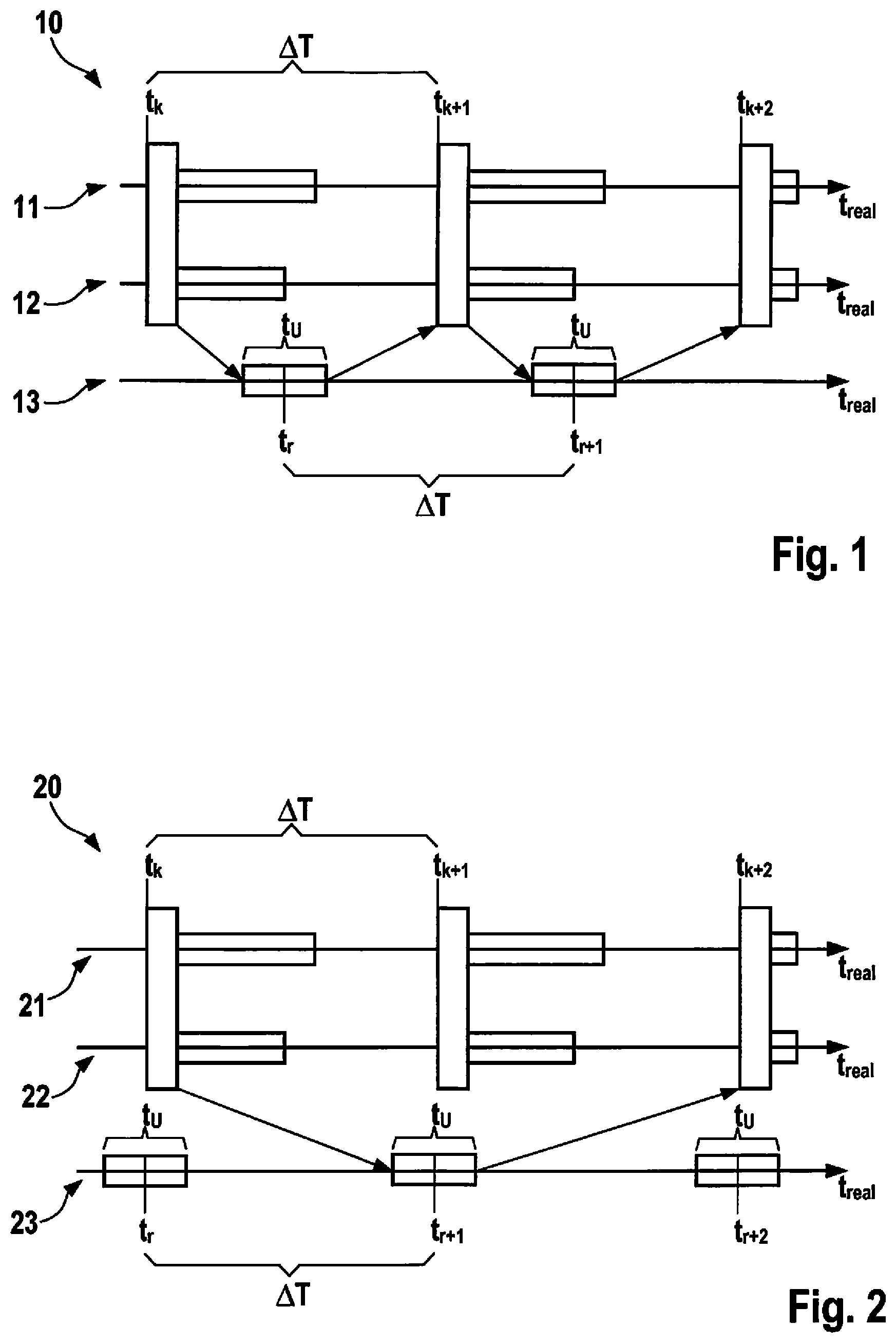
[0016] FIG. 1 and FIG. 2 illustrate the effect that such a mutual shift of the two computing clocks t.sub.r, t.sub.r+1, t.sub.r+2, . . . and t.sub.k, t.sub.k+1, t.sub.k+2, . . . has on the data exchange. The illustrated bars identify the time period of the calculations in the respective subsystems. Horizontal bars represent the computing period of the models of the offline simulation or the cycle time t.sub.U, which is required for the communication with the real-time system; perpendicular bars identify the duration of the data exchange between the models of offline simulations 11, 12 or 21, 22, which is coordinated by the master of the offline simulation.
[0017] FIG. 1 shows a simulation run 10, in which the starting instants of the two computing clocks t.sub.r, t.sub.r+1, t.sub.r+2, . . . and t.sub.k, t.sub.k+1, t.sub.k+2, . . . behave in such a way towards each other that a data exchange within a macro time increment .DELTA.T is possible. Values of offline simulations 11, 12 at instant t.sub.k are thereby able to be processed by real-time system 13 at instant t.sub.r under consideration of cycle time t.sub.U, and its results are available again to offline simulations 11, 12 at instant t.sub.k+1.
[0018] FIG. 2 shows a simulation run 20 in which the starting instants of the computing clocks t.sub.r, t.sub.r+1, t.sub.r+2, . . . and t.sub.k, t.sub.k+1, t.sub.k+2, . . . behave in a disadvantageous manner towards one another. Here, values of offline simulations 21, 22 at instant t.sub.k are unable to be processed by real-time system 23 at instant t.sub.r due to cycle time t.sub.u, and its results are therefore only available again to offline simulations 21, 22 at instant t.sub.k+2. This doubles the delay during the data exchange across the entire simulation run to two macro increments 2.DELTA.T.
[0019] The results of simulation runs during which the delay amounts to two increments 2.DELTA.T are considerably poorer than those that are obtained when the delay is shorter. A central aspect of the proposed approach thus is the synchronization of the two computing clocks t.sub.r, t.sub.r+1, t.sub.r+2, . . . and t.sub.k, t.sub.k+1, t.sub.k+2, . . . in order to optimize their position relative to each other and to standardize the delays. This avoids simulation runs during which the processing clocks t.sub.r, t.sub.r+1, t.sub.r+2, . . . and t.sub.k, t.sub.k+1, t.sub.k+2, . . . are positioned unfavorably relative to each other, as illustrated in FIG. 2. This ensures that the delays are minimized and standardized in all simulation runs.
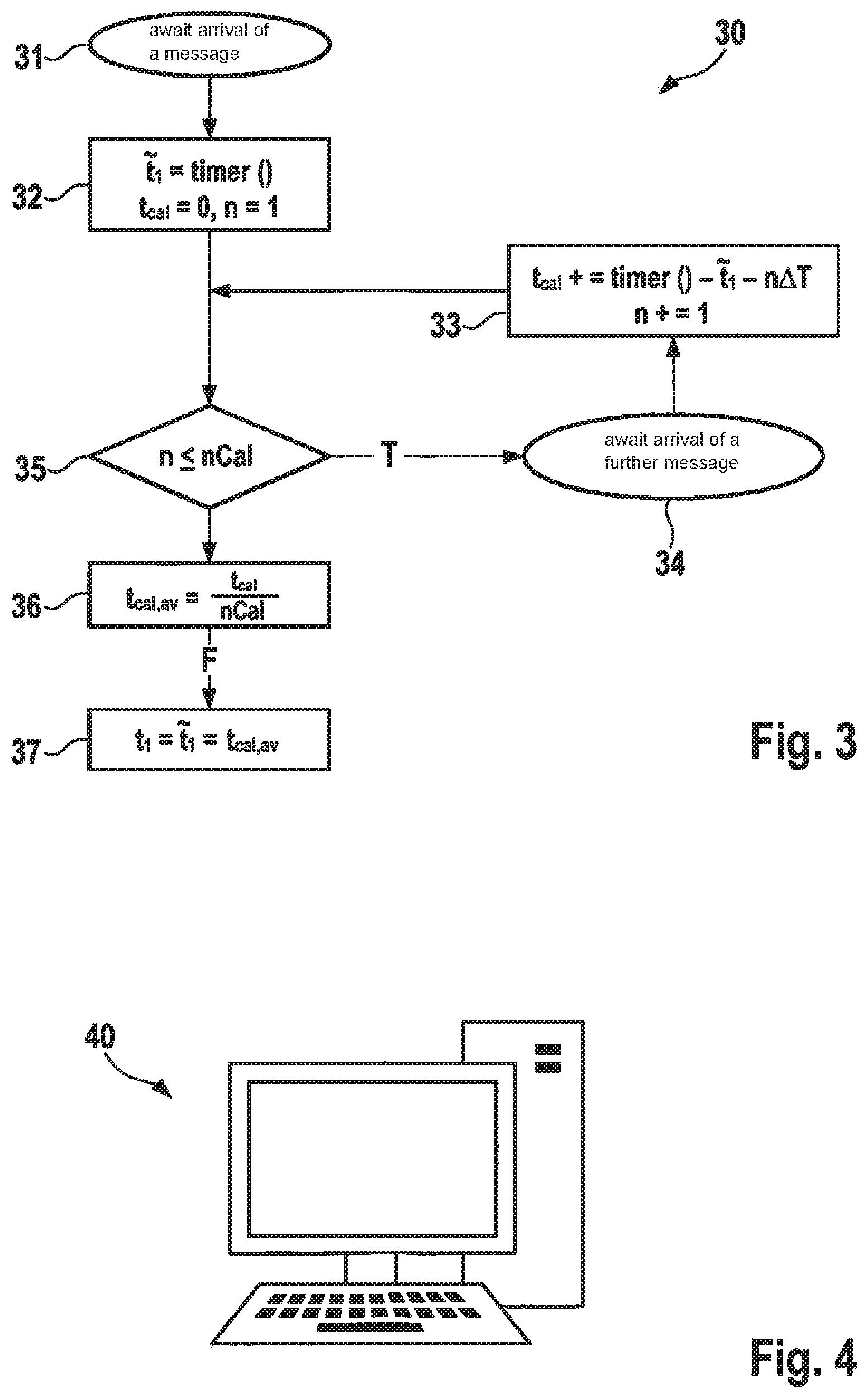
[0020] Toward this end, according to the method (30) illustrated in FIG. 3, the computing clock of the already running real-time system is ascertained at the beginning of the offline simulation and the computing clock of the offline simulation is adapted thereto prior to the start of the simulation. To do so, the clock t.sub.1+k.DELTA.T at which the offline simulation receives messages from the real-time system first has to be measured. With the aid of known cycle time t.sub.U, the optimal computing clock of the offline simulation is able to be determined therefrom. Since macro increment .DELTA.T is known as well, only starting instant t.sub.1 needs to be determined in order to determine the clock.
[0021] For this purpose, first the arrival of a message from the real-time system (event 31) is awaited. Instant {tilde over (t)}.sub.1 of this event is measured (process 32). Since a single time measurement may be imprecise, which should be taken into account when using a single-user computer for the execution of the method (30), for instance, the measurement (32) is averaged in the next step with the aid of further measurements (33). A further message (event 34) is awaited for this purpose, which should arrive precisely one macro increment .DELTA.T after the previous message. The value of variables t.sub.cal is increased by the deviation between the measured and the expected times (process 33). This process is repeated (decision 35, branch T) until the number n of the processed messages corresponds to the provided random sampling scope nCal (decision 35, branch F). Then, the average deviation t.sub.cal,av of the further time measurements is ascertained (process 36). In the final step (process 37), t.sub.1 is determined by deducting t.sub.cal,av from {tilde over (t)}.sub.1. With knowledge of macro increment .DELTA.T, clock t.sub.1+k.DELTA.T at which messages are arriving from the real-time system is thus determined.
[0022] This method (30) may be implemented in software or hardware, for example, or in a mixed form of software and hardware such as in a single user computer (40) as illustrated by the schematic representation of FIG. 4.
* * * * *
D00000
D00001
D00002
XML
uspto.report is an independent third-party trademark research tool that is not affiliated, endorsed, or sponsored by the United States Patent and Trademark Office (USPTO) or any other governmental organization. The information provided by uspto.report is based on publicly available data at the time of writing and is intended for informational purposes only.
While we strive to provide accurate and up-to-date information, we do not guarantee the accuracy, completeness, reliability, or suitability of the information displayed on this site. The use of this site is at your own risk. Any reliance you place on such information is therefore strictly at your own risk.
All official trademark data, including owner information, should be verified by visiting the official USPTO website at www.uspto.gov. This site is not intended to replace professional legal advice and should not be used as a substitute for consulting with a legal professional who is knowledgeable about trademark law.