Optical Imaging System
A1
U.S. patent application number 15/772854 was filed with the patent office on 2020-08-13 for optical imaging system. This patent application is currently assigned to Zhejiang Sunny Optical Co., Ltd. The applicant listed for this patent is Zhejiang Sunny Optical Co., Ltd. Invention is credited to Fujian DAI, Jianke WENREN.
| Application Number | 20200257084 15/772854 |
| Document ID | 20200257084 / US20200257084 |
| Family ID | 1000004829265 |
| Filed Date | 2020-08-13 |
| Patent Application | download [pdf] |


View All Diagrams
| United States Patent Application | 20200257084 |
| Kind Code | A1 |
| DAI; Fujian ; et al. | August 13, 2020 |
OPTICAL IMAGING SYSTEM
Abstract
The present disclosure discloses an optical imaging system, the optical imaging system having an effective focal length f and an entrance pupil diameter EPD, and comprising sequentially, along an optical axis from an object side to an image side, a first lens, a second lens, a third lens, a fourth lens, a fifth lens, a sixth lens and a seventh lens. The third lens has a negative refractive power; the fifth lens has a positive refractive power or a negative refractive power, and an image side surface of the fifth lens is a convex surface; the seventh lens has a positive refractive power or a negative refractive power, and an object side surface of the seventh lens is a concave surface; the first lens, the second lens, the fourth lens, and the sixth lens respectively have a positive refractive power or a negative refractive power.
| Inventors: | DAI; Fujian; (Ningbo City, CN) ; WENREN; Jianke; (Ningbo City, CN) | ||||||||||
| Applicant: |
|
||||||||||
|---|---|---|---|---|---|---|---|---|---|---|---|
| Assignee: | Zhejiang Sunny Optical Co.,
Ltd Ningbo City, Zhejiang Province CN |
||||||||||
| Family ID: | 1000004829265 | ||||||||||
| Appl. No.: | 15/772854 | ||||||||||
| Filed: | September 21, 2017 | ||||||||||
| PCT Filed: | September 21, 2017 | ||||||||||
| PCT NO: | PCT/CN2017/102633 | ||||||||||
| 371 Date: | May 2, 2018 |
| Current U.S. Class: | 1/1 |
| Current CPC Class: | G02B 9/60 20130101; G02B 9/64 20130101; G02B 13/0045 20130101 |
| International Class: | G02B 13/00 20060101 G02B013/00; G02B 9/64 20060101 G02B009/64 |
Foreign Application Data
| Date | Code | Application Number |
|---|---|---|
| May 15, 2017 | CN | 201710338407.9 |
| May 15, 2017 | CN | 201720531917.3 |
Claims
1. An optical imaging system, having an effective focal length f and an entrance pupil diameter EPD, and the optical imaging system comprising sequentially, along an optical axis from an object side to an image side, a first lens, a second lens, a third lens, a fourth lens, a fifth lens, a sixth lens and a seventh lens, wherein the third lens has a negative refractive power; the fifth lens has a positive refractive power or a negative refractive power, and an image side surface of the fifth lens is a convex surface; the seventh lens has a positive refractive power or a negative refractive power, and an object side surface of the seventh lens is a concave surface; the first lens, the second lens, the fourth lens, and the sixth lens respectively have a positive refractive power or a negative refractive power; and a distance TTL from an object side surface of the first lens to an image plane on the optical axis and half of a diagonal length ImgH of an effective pixel area on the image plane of the optical imaging system satisfy: TTL/ImgH<1.6.
2. The optical imaging system according to claim 1, wherein the effective focal length f and the entrance pupil diameter EPD satisfy: f/EPD<1.6.
3. The optical imaging system according to claim 1, wherein a distance SL from an aperture of the optical imaging system to the image plane on the optical axis and the distance TTL from the object side surface of the first lens to the image plane on the optical axis satisfy: SL/TTL<0.85.
4. The optical imaging system according to claim 1, wherein a center thickness CT1 of the first lens on the optical axis, a center thickness CT2 of the second lens on the optical axis and a center thickness CT4 of the fourth lens on the optical axis satisfy: 1.5<(CT1+CT2)/CT4<2.3.
5. The optical imaging system according to claim 4, wherein the center thickness CT2 of the second lens on the optical axis and the center thickness CT4 of the fourth lens on the optical axis satisfy: 0.75<CT2/CT4<1.5.
6. The optical imaging system according to claim 1, wherein 0<SAG41/SAG42<0.5, wherein SAG41 represents a distance from an intersection point of an object side surface of the fourth lens and the optical axis to an effective radius vertex of the object side surface of the fourth lens on the optical axis; and SAG42 represents a distance from an intersection point of an image side surface of the fourth lens and the optical axis to an effective radius vertex of the image side surface of the fourth lens on the optical axis.
7. The optical imaging system according to claim 1, wherein a combined focal length f12 of the first lens and the second lens and a combined focal length f56 of the fifth lens and the sixth lens satisfy: 0.6<f12/f56<1.2.
8. (canceled)
9. The optical imaging system according to claim 1, wherein the half of the diagonal length ImgH of the effective pixel area on the image plane of the optical imaging system and the effective focal length f of the optical imaging system satisfy: 0.8<ImgH/f<1.
10. The optical imaging system according to claim 1, wherein a spacing distance T34 between the third lens and the fourth lens on the optical axis and a spacing distance T45 between the fourth lens and the fifth lens on the optical axis T45 satisfy: 0.5<T34/T45<1.
11.-12. (canceled)
13. An optical imaging system, having an effective focal length f and an entrance pupil diameter EPD, and the optical imaging system comprising sequentially, along an optical axis from an object side to an image side, a first lens, a second lens, a third lens, a fourth lens, a fifth lens, and a plurality of subsequent lenses, wherein the third lens has a negative refractive power; the fifth lens has a positive refractive power or a negative refractive power, and an image side surface of the fifth lens is a convex surface; the first lens, the second lens and the fourth lens respectively have a positive refractive power or a negative refractive power; and a distance SL from an aperture of the optical imaging system to an image plane on the optical axis and a distance TTL from an object side surface of the first lens to the image plane on the optical axis satisfy: SL/TTL<0.85.
14. The optical imaging system according to claim 13, wherein the plurality of subsequent lenses comprise at least a sixth lens and a seventh lens, wherein the sixth lens has a positive refractive power or a negative refractive power; and the seventh lens has a positive refractive power or a negative refractive power, and an object side surface of the seventh lens is a concave surface.
15. The optical imaging system according to claim 13, wherein the distance TTL from the object side surface of the first lens to the image plane on the optical axis and half of a diagonal length ImgH of an effective pixel area on the image plane of the optical imaging system satisfy: TTL/ImgH<1.6.
16. The optical imaging system according to claim 13, wherein the effective focal length f of the optical imaging system and the entrance pupil diameter EPD satisfy: f/EPD<1.6.
17.-18. (canceled)
19. The optical imaging system according to claim 13, wherein 0<SAG41/SAG42<0.5, wherein SAG41 represents a distance from an intersection point of an object side surface of the fourth lens and the optical axis to an effective radius vertex of the object side surface of the fourth lens on the optical axis; and SAG42 represents a distance from an intersection point of an image side surface of the fourth lens and the optical axis to an effective radius vertex of the image side surface of the fourth lens on the optical axis.
20. The optical imaging system according to claim 13, wherein a combined focal length f12 of the first lens and the second lens and a combined focal length f56 of the fifth lens and the sixth lens satisfy: 0.6<f12/f56<1.2.
21. The optical imaging system according to claim 13, wherein an effective radius DT11 of the object side surface of the first lens and an effective radius DT52 of the image side surface of the fifth lens satisfy: 0.7<DT11/DT52<1.
22. The optical imaging system according to claim 13, wherein half of a diagonal length of an effective pixel area on the image plane of the optical imaging system ImgH and the effective focal length f of the optical imaging system satisfy: 0.8<ImgH/f<1.
23. The optical imaging system according to claim 13, wherein a spacing distance T34 between the third lens and the fourth lens on the optical axis and a spacing distance T45 between the fourth lens and the fifth lens on the optical axis satisfy: 0.5<T34/T45<1.
24. The optical imaging system according to claim 14, wherein an effective focal length f5 of the fifth lens and an effective focal length f7 of the seventh lens satisfy: 1.5<|f5/f7|<2.5.
25. The optical imaging system according to claim 14, wherein a radius of curvature R13 of the object side surface of the seventh lens and a radius of curvature R14 of an image side surface of the seventh lens satisfy: -1.8<R13/R14<-1.
Description
CROSS-REFERENCE TO RELATED APPLICATIONS
[0001] This application claims the priorities and rights of Chinese Patent Application No. 201710338407.9 and Chinese Patent Application No. 201720531917.3 filed with the State Intellectual Property Office of China (SIPO) on May 15, 2017, the disclosures of which are hereby incorporated by reference in their entireties.
TECHNICAL FIELD
[0002] The present disclosure relates to an optical imaging system, and specifically, relates to an optical imaging system composed of seven lenses.
BACKGROUND
[0003] As the science and technology develop, there is an increasing demand for high-resolution lens assemblies in mobile phones on the mobile phone market. Since thicknesses of the mobile phones are reduced, the total length of a lens assembly is limited, thereby increasing the difficulty in designing a mobile phone lens assembly. Currently, an often used photosensitive element in an optical system is a CCD (Charge-Coupled Device) or a complementary metal-oxide semiconductor (CMOS). As imaging sensors enhance their performances and become smaller in size, corresponding camera lens assemblies also need to satisfy requirements on the high image quality and miniaturization.
[0004] To satisfy the miniaturization requirement, a typical configuration of an existing lens assembly has an F-number of 2.0 or above. However, with the constant development of smart phones and other portable electronic products, higher requirements on imaging lens assemblies are brought forward, especially in situations such as lack of light (e.g., cloudy and rainy days, dusk, etc.) and hand trembling, thus the F-number of 2.0 or above has been unable to meet higher order imaging requirements.
[0005] Therefore, the present invention proposes a miniaturized optical imaging system having a large aperture and a high image quality.
SUMMARY
[0006] The technical solution provided by the present disclosure at least partially solves the technical problems described above.
[0007] According to an aspect, the present disclosure provides an optical imaging system, the optical imaging system having an effective focal length f and an entrance pupil diameter EPD, and comprising sequentially, along an optical axis from an object side to an image side, a first lens, a second lens, a third lens, a fourth lens, a fifth lens, a sixth lens and a seventh lens. The third lens has a negative refractive power; the fifth lens has a positive refractive power or a negative refractive power, and an image side surface of the fifth lens is a convex surface; the seventh lens has a positive refractive power or a negative refractive power, and an object side surface of the seventh lens is a concave surface; the first lens, the second lens, the fourth lens, and the sixth lens respectively have a positive refractive power or a negative refractive power; and a distance TTL from an object side surface of the first lens to an image plane on the optical axis and half of a diagonal length ImgH of an effective pixel area on the image plane of the optical imaging system satisfy: TTL/ImgH<1.6, for example, TTL/ImgH.ltoreq.1.546.
[0008] In the present disclosure, a plurality of pieces (for example, seven pieces) of lenses are used. By properly allocating a relationship between the total effective focal length and the entrance pupil diameter of the optical imaging system, the system is enabled to have a large aperture advantage in the process of increasing an amount of light admitted, and an image effect in a dark environment is enhanced; at the same time an aberration of an edge field of view is reduced.
[0009] According to another aspect, the present disclosure further provides an optical imaging system, the optical imaging system having an effective focal length f and an entrance pupil diameter EPD, and comprising sequentially, along an optical axis from an object side to an image side, a first lens, a second lens, a third lens, a fourth lens, a fifth lens, and a plurality of subsequent lenses. The third lens has a negative refractive power; the fifth lens has a positive refractive power or a negative refractive power, and an image side surface of the fifth lens is a convex surface; the first lens, the second lens and the fourth lens respectively have a positive refractive power or a negative refractive power; and a distance SL from an aperture of the optical imaging system to an image plane on the optical axis and a distance TTL from an object side surface of the first lens to the image plane on the optical axis may satisfy: SL/TTL<0.85, for example, SL/TTL.ltoreq.0.808.
[0010] In an implementation, the effective focal length f of the optical imaging system and the entrance pupil diameter EPD of the optical imaging system may satisfy: f/EPD<1.6, for example, f/EPD.ltoreq.1.550.
[0011] In an implementation, a center thickness CT1 of the first lens on the optical axis, a center thickness CT2 of the second lens on the optical axis and a center thickness CT4 of the fourth lens on the optical axis may satisfy: 1.5<(CT1+CT2)/CT4<2.3, for example: 1.880.ltoreq.(CT1+CT2)/CT4.ltoreq.2.140.
[0012] In an implementation, the center thickness CT2 of the second lens on the optical axis and the center thickness CT4 of the fourth lens on the optical axis may satisfy: 0.75<CT2/CT4<1.5, for example: 0.794.ltoreq.CT2/CT4.ltoreq.1.498.
[0013] In an implementation, a distance SAG41 from an intersection point of an object side surface of the fourth lens and the optical axis to an effective radius vertex of the object side surface of the fourth lens on the optical axis and a distance SAG42 from an intersection point of an image side surface of the fourth lens and the optical axis to an effective radius vertex of the image side surface of the fourth lens on the optical axis may satisfy: 0<SAG41/SAG42<0.5, for example: 0.016.ltoreq.SAG41/SAG42.ltoreq.0.439.
[0014] In an implementation, a combined focal length f12 of the first lens and the second lens and a combined focal length f56 of the fifth lens and the sixth lens may satisfy: 0.6<f12/f56<1.2, for example: 0.796.ltoreq.f12/f56.ltoreq.561.109.
[0015] In an implementation, an effective radius DT11 of the object side surface of the first lens and an effective radius DT52 of the image side surface of the fifth lens may satisfy: 0.7<DT11/DT52<1, for example: 0.822.ltoreq.DT11/DT52.ltoreq.0.922.
[0016] In an implementation, the half of the diagonal length ImgH of the effective pixel area on the image plane of the optical imaging system and the effective focal length f of the optical imaging system may satisfy: 0.8<ImgH/f<1, for example: 0.844.ltoreq.ImgH/f.ltoreq.0.871.
[0017] In an implementation, a spacing distance T34 between the third lens and the fourth lens on the optical axis and a spacing distance T45 between the fourth lens and the fifth lens on the optical axis may satisfy: 0.5<T34/T45<1, for example: 0.540.ltoreq.T34/T45.ltoreq.0.886.
[0018] In an implementation, an effective focal length f5 of the fifth lens and an effective focal length f7 of the seventh lens may satisfy: 1.5<|f5/f7|<2.5, for example: 1.506.ltoreq.|f5/f7|.ltoreq.2.322.
[0019] In an implementation, a radius of curvature R13 of the object side surface of the seventh lens and a radius of curvature R14 of an image side surface of the seventh lens may satisfy: -1.8<R13/R14<-1, for example: -1.778.ltoreq.R13/R14.ltoreq.-1.099.
[0020] The optical imaging system with the above configuration may further have at least one of the beneficial effects of ultra-thin, miniaturization, a large aperture, a high image quality, a low sensitivity, balanced aberrations, a better ability of eliminating distortion and the like.
BRIEF DESCRIPTION OF THE DRAWINGS
[0021] The above and other advantages of implementations of the present disclosure will become apparent from the following detailed description with reference to the accompanying drawings, which are intended to illustrate the exemplary implementations of the present disclosure rather than limit them. In the drawings:
[0022] FIG. 1 is a schematic structural diagram illustrating an optical imaging system according to Embodiment 1 of the present disclosure;
[0023] FIG. 2A shows a longitudinal aberration curve of the optical imaging system according to Embodiment 1;
[0024] FIG. 2B shows an astigmatic curve of the optical imaging system according to Embodiment 1;
[0025] FIG. 2C shows a distortion curve of the optical imaging system according to Embodiment 1;
[0026] FIG. 2D shows a lateral color curve of the optical imaging system according to Embodiment 1;
[0027] FIG. 3 is a schematic structural diagram illustrating an optical imaging system according to Embodiment 2 of the present disclosure;
[0028] FIG. 4A shows a longitudinal aberration curve of the optical imaging system according to Embodiment 2;
[0029] FIG. 4B shows an astigmatic curve of the optical imaging system according to Embodiment 2;
[0030] FIG. 4C shows a distortion curve of the optical imaging system according to Embodiment 2;
[0031] FIG. 4D shows a lateral color curve of the optical imaging system according to Embodiment 2;
[0032] FIG. 5 is a schematic structural diagram illustrating an optical imaging system according to Embodiment 3 of the present disclosure;
[0033] FIG. 6A shows a longitudinal aberration curve of the optical imaging system according to Embodiment 3;
[0034] FIG. 6B shows an astigmatic curve of the optical imaging system according to Embodiment 3;
[0035] FIG. 6C shows a distortion curve of the optical imaging system according to Embodiment 3;
[0036] FIG. 6D shows a lateral color curve of the optical imaging system according to Embodiment 3;
[0037] FIG. 7 is a schematic structural diagram illustrating an optical imaging system according to Embodiment 4 of the present disclosure;
[0038] FIG. 8A shows a longitudinal aberration curve of the optical imaging system according to Embodiment 4;
[0039] FIG. 8B shows an astigmatic curve of the optical imaging system according to Embodiment 4;
[0040] FIG. 8C shows a distortion curve of the optical imaging system according to Embodiment 4;
[0041] FIG. 8D shows a lateral color curve of the optical imaging system according to Embodiment 4;
[0042] FIG. 9 is a schematic structural diagram illustrating an optical imaging system according to Embodiment 5 of the present disclosure;
[0043] FIG. 10A shows a longitudinal aberration curve of the optical imaging system according to Embodiment 5;
[0044] FIG. 10B shows an astigmatic curve of the optical imaging system according to Embodiment 5;
[0045] FIG. 10C shows a distortion curve of the optical imaging system according to Embodiment 5;
[0046] FIG. 10D shows a lateral color curve of the optical imaging system according to Embodiment 5;
[0047] FIG. 11 is a schematic structural diagram illustrating an optical imaging system according to Embodiment 6 of the present disclosure;
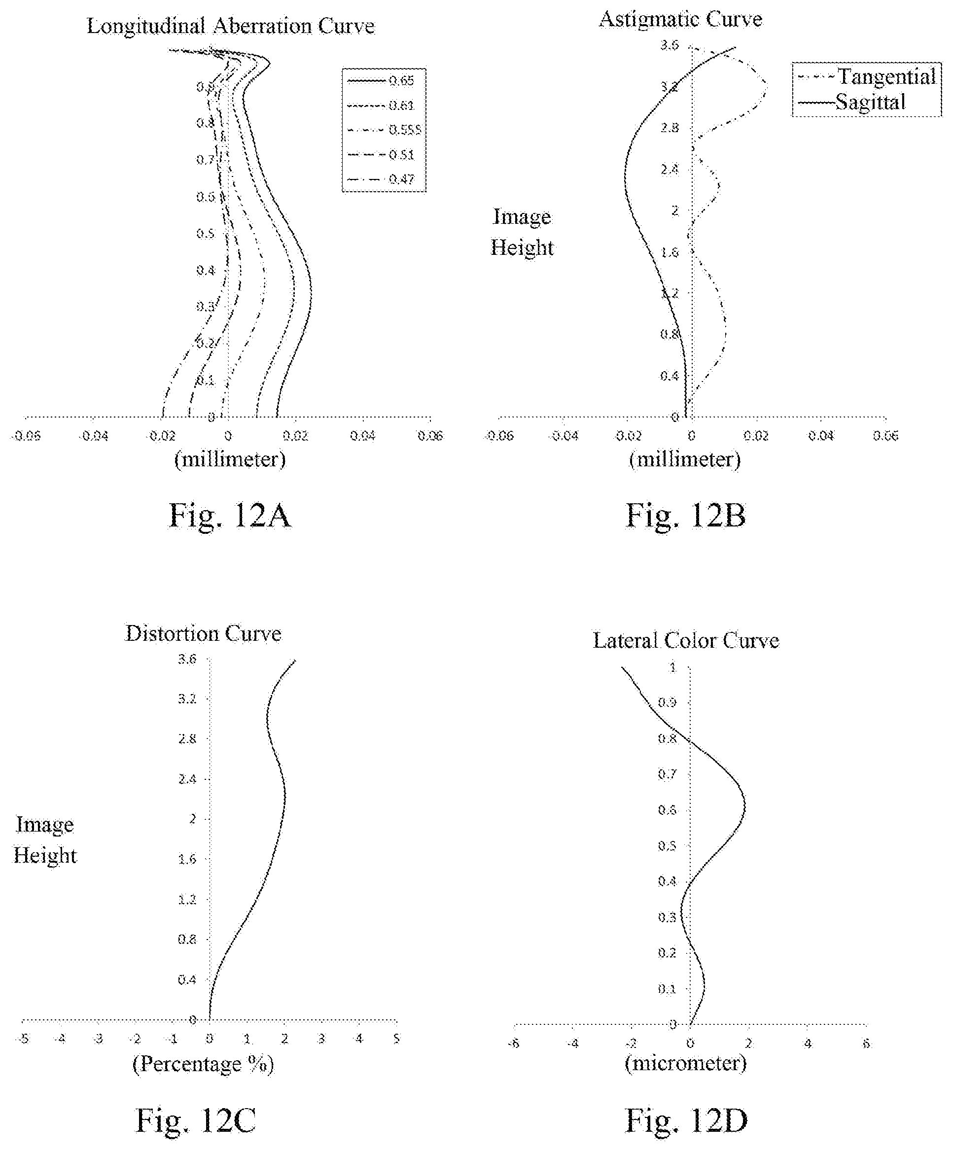
[0048] FIG. 12A shows a longitudinal aberration curve of the optical imaging system according to Embodiment 6;
[0049] FIG. 12B shows an astigmatic curve of the optical imaging system according to Embodiment 6;
[0050] FIG. 12C shows a distortion curve of the optical imaging system according to Embodiment 6;
[0051] FIG. 12D shows a lateral color curve of the optical imaging system according to Embodiment 6;
[0052] FIG. 13 is a schematic structural diagram illustrating an optical imaging system according to Embodiment 7 of the present disclosure;
[0053] FIG. 14A shows a longitudinal aberration curve of the optical imaging system according to Embodiment 7;
[0054] FIG. 14B shows an astigmatic curve of the optical imaging system according to Embodiment 7;
[0055] FIG. 14C shows a distortion curve of the optical imaging system according to Embodiment 7; and
[0056] FIG. 14D shows a lateral color curve of the optical imaging system according to Embodiment 7.
DETAILED DESCRIPTION OF EMBODIMENTS
[0057] For a better understanding of the present disclosure, various aspects of the present disclosure will be described in more detail with reference to the accompanying drawings. It should be understood that the detailed description is merely an illustration for the exemplary implementations of the present disclosure, rather than a limitation to the scope of the present disclosure in any way. Throughout the specification, the same reference numerals refer to the same elements. The expression "and/or" includes any and all combinations of one or more of the associated listed items.
[0058] It should be noted that in the present specification, the expressions of the first, the second, etc. are only used to distinguish one feature from another, without indicating any limitations to the features. Thus, the first lens discussed below also could be referred to as the second lens without departing from the teachings of the present disclosure.
[0059] In the accompanying drawings, the thickness, size and shape of the lens have been slightly exaggerated for the convenience of explanation. Specifically, shapes of spherical surfaces or aspheric surfaces shown in the accompanying drawings are shown by way of example. That is, shapes of spherical surfaces or aspheric surfaces are not limited to the shapes of the spherical surfaces or the aspheric surfaces shown in the accompanying drawings. The accompanying drawings are merely illustrative and not strictly drawn to scale.
[0060] It should be further understood that the terms "comprising," "including," "having" and variants thereof, when used in this specification, specify the presence of stated features, entireties, steps, operations, elements and/or components, but do not exclude the presence or addition of one or more other features, entireties, steps, operations, elements, components and/or combinations thereof. In addition, expressions, such as "at least one of," when preceding a list of features, modify the entire list of features rather than an individual element in the list. Further, the use of "may," when describing implementations of the present disclosure, relates to "one or more implementations of the present disclosure." In addition, the term "exemplary" is intended to refer to an example or illustration.
[0061] As used herein, the terms "substantially," "about" and similar terms are used as a term of approximation rather than as a term of degree, and are intended to account for the inherent deviations in measured or calculated values that would be recognized by those of ordinary skill in the art.
[0062] Unless otherwise defined, all terms (including technical and scientific terms) used herein have the same meaning as commonly understood by those of ordinary skill in the art to which the present disclosure belongs. It should be further understood that terms, such as those defined in commonly used dictionaries, should be interpreted as having a meaning that is consistent with their meaning in the context of the relevant art and will not be interpreted in an idealized or overly formal sense unless expressly so defined herein.
[0063] In addition, the paraxial area refers to an area near the optical axis. The first lens is the lens closest to the object and the seventh lens is the lens closest to the photosensitive element. Here, the surface closest to the object in each lens is referred to as the object side surface, and the surface closest to the image plane in each lens is referred to as the image side surface.
[0064] It should also be noted that the embodiments in the present disclosure and the features in the embodiments may be combined with each other on a non-conflict basis. The present disclosure will be described below in detail with reference to the accompanying drawings and in combination with the embodiments.
[0065] The present disclosure will be further described below in combination with specific embodiments.
[0066] The optical imaging system according to exemplary implementations of the present disclosure has, for example, seven lenses, i.e., a first lens, a second lens, a third lens, a fourth lens, a fifth lens, a sixth lens and a seventh lens. The seven lenses are arranged in sequence along an optical axis from an object side to an image side. The optical imaging system may have an effective focal length f and an entrance pupil diameter EPD.
[0067] According to the exemplary implementations, the third lens may have a negative refractive power. The fifth lens may have a positive refractive power or a negative refractive power, and an image side surface of the fifth lens is a convex surface. The seventh lens may have a positive refractive power or a negative refractive power, and an object side surface of the seventh lens is a concave surface. The first lens, the second lens, the fourth lens, and the sixth lens may respectively have a positive refractive power or a negative refractive power. By properly controlling the positive and negative refractive power distribution of each lens in the system, lower-order aberrations of the system can be effectively balanced and controlled, so that the system obtains a better image quality.
[0068] According to the exemplary implementations, a distance TTL from an object side surface of the first lens to an image plane on the optical axis and half of a diagonal length ImgH of an effective pixel area on the image plane of the optical imaging system may satisfy: TTL/ImgH<1.6, and more specifically, may further satisfy: TTL/ImgH.ltoreq.1.546. By controlling the ratio of the total optical length to the image height of the system, the total size of the optical imaging system can be effectively compressed to realize the ultra-thin characteristic and the miniaturization of the optical imaging system, so that the above optical imaging system can be better applicable to a size-limited system such as systems in portable electronic products.
[0069] According to the exemplary implementations, the effective focal length f of the optical imaging system and the entrance pupil diameter EPD of the optical imaging system may satisfy: f/EPD<1.6, and more specifically, may further satisfy: f/EPD.ltoreq.1.550. Such a configuration can enable the system to have advantages of a large diaphragm and a large aperture in the process of increasing an amount of light admitted, thus reducing an aberration of an edge field of view, and at the same time enhancing an image effect in a dark environment, so that the system has a low sensitivity.
[0070] According to the exemplary implementations, a distance SL from an aperture of the optical imaging system to the image plane on the optical axis and the distance TTL from the object side surface of the first lens to the image plane on the optical axis may satisfy: SL/TTL<0.85, and more specifically, may further satisfy: SL/TTL.ltoreq.0.808. By effectively controlling the total optical length of the system, it is conductive to realizing the miniaturization of the system.
[0071] According to the exemplary implementations, a center thickness CT1 of the first lens on the optical axis, a center thickness CT2 of the second lens on the optical axis and a center thickness CT4 of the fourth lens on the optical axis may satisfy: 1.5<(CT1+CT2)/CT4<2.3, and more specifically, may further satisfy: 1.880.ltoreq.(CT1+CT2)/CT4.ltoreq.2.140. The ratio, if too large, is not conducive to eliminating the chromatic aberrations of the system. If the ratio is too small, it will result in the overly-thinness of the lenses and a poor technology. Satisfying the above formula can effectively balance the chromatic aberrations of the system and the technology.
[0072] According to the exemplary implementations, the center thickness CT2 of the second lens on the optical axis and the center thickness CT4 of the fourth lens on the optical axis may satisfy: 0.75<CT2/CT4<1.5, and more specifically, may further satisfy: 0.794.ltoreq.CT2/CT4.ltoreq.1.498. Such a configuration is conductive to distributing the sizes of the lenses evenly, ensuring the assembling stability, reducing aberrations of the overall system and shortening the total length of the optical imaging system.
[0073] According to the exemplary implementations, a distance SAG41 from an intersection point of an object side surface of the fourth lens and the optical axis to an effective radius vertex of the object side surface of the fourth lens on the optical axis and a distance SAG42 from an intersection point of an image side surface of the fourth lens and the optical axis to an effective radius vertex of the image side surface of the fourth lens on the optical axis may satisfy: 0<SAG41/SAG42<0.5, and more specifically, may further satisfy: 0.016.ltoreq.SAG41/SAG42.ltoreq.0.439. This ratio can reduce the risk of ghost images occurred in the system and effectively balance the size of the system and the technology.
[0074] According to the exemplary implementations, a combined focal length f12 of the first lens and the second lens and a combined focal length f56 of the fifth lens and the sixth lens may satisfy: 0.6<f12/f56<1.2, and more specifically, may further satisfy: 0.796.ltoreq.f12/f56.ltoreq.1.109. The ratio, if too large, will cause the fifth lens and the sixth lens to bear too many refractive powers, which results in a poor technology and is not conductive to correcting the aberrations. If the ratio is too small, it will make the calibers of the first lens and the second lens hard to be enlarged, resulting in a poor assembling technology. Satisfying the above formula can effectively ensure the technology and the assembling technology of the lenses.
[0075] According to the exemplary implementations, an effective radius DT11 of the object side surface of the first lens and an effective radius DT52 of the image side surface of the fifth lens may satisfy: 0.7<DT11/DT52<1, and more specifically, may further satisfy: 0.822.ltoreq.DT11/DT52.ltoreq.0.922. The ratio, if too large, is not conducive to the miniaturization of the system. If the ratio is too small, it is not conductive to the assembling. The ratio effectively balances the size and the technology of the lens assembly.
[0076] According to the exemplary implementations, the half of the diagonal length ImgH of the effective pixel area on the image plane of the optical imaging system and the effective focal length f of the optical imaging system may satisfy: 0.8<ImgH/f<1, and more specifically, may further satisfy: 0.844.ltoreq.ImgH/f.ltoreq.0.871. In a system less than 180.degree., with the same ImgH, a focal length too long means larger negative distortion, and a focal length too short means a poor technology, which is difficult to ensure the brightness of the edge of the image plane. Satisfying the above formula takes into account the distortion, the image quality and the system manufacturability.
[0077] According to the exemplary implementations, a spacing distance T34 between the third lens and the fourth lens on the optical axis and a spacing distance T45 between the fourth lens and the fifth lens on the optical axis may satisfy: 0.5<T34/T45<1, and more specifically, may further satisfy: 0.540.ltoreq.T34/T45.ltoreq.0.886. Such a configuration is conductive to ensuring the molding technology and the assembling stability of the lenses.
[0078] According to the exemplary implementations, an effective focal length f5 of the fifth lens and an effective focal length f7 of the seventh lens may satisfy: 1.5<|f5/f7|<2.5, and more specifically, may further satisfy: 1.506.ltoreq.|f5/f7|.ltoreq.2.322. By properly allocating the refractive powers of the fifth lens and the seventh lens, the aberrations of the overall system can be effectively reduced, and the sensitivity of the system can be effectively lowered.
[0079] In application, a radius of curvature of each mirror surface may be optimized. For example, in the exemplary implementations, a radius of curvature R13 of the object side surface of the seventh lens and a radius of curvature R14 of an image side surface of the seventh lens may satisfy: -1.8<R13/R14<-1, and more specifically, may further satisfy: -1.778.ltoreq.R13/R14.ltoreq.-1.099. Such a configuration is conductive to correcting the chromatic aberrations of the system, and the ratio realizes the balance of various aberrations of the optical imaging system.
[0080] In the exemplary implementations, the optical imaging system may further be provided with an aperture STO for limiting the light beam, thereby adjusting the amount of light admitted, and improving the image quality. The optical imaging system according to the above implementations of the present disclosure may use a plurality of lenses, for example, seven lenses described above. By properly allocating the refractive power and surface type of each lens, the center thickness of each lens, axial spacing distances between the lenses, etc., it is possible to effectively enlarge the aperture of the optical imaging system, lower the system sensitivity, ensure the miniaturization of the lens assembly and improve the image quality, thus making the optical imaging system more conducive to producing and processing and applicable to portable electronic products. In the implementations of the present disclosure, at least one of the mirror surfaces of the lenses is an aspheric mirror surface. The characteristic of the aspheric lens is: from the center of the lens to the periphery, the curvature is continuously changing. Unlike the spherical lens with a constant curvature from the center of the lens to the periphery, the aspheric lens has a better radius-of-curvature characteristic, has an advantage of improving a distortion aberration and an astigmatic aberration, and is capable of making the visual field become larger and realistic. Using the aspheric lens, an aberration occurring at the time of imaging can be eliminated as much as possible, thereby improving the image quality. In addition, the use of the aspheric lens can also effectively reduce the number of the lenses in the optical system.
[0081] However, it should be understood by those skilled in the art that the various results and advantages described in the Specification may be obtained by changing the number of lenses forming the lens assembly without departing from the technical solution sought to be protected by the present disclosure. For example, although seven lenses are described as an example in the implementations, the optical imaging system is not limited to include seven lenses. If desired, the optical imaging system may also include other numbers of lenses.
[0082] Specific embodiments of the optical imaging system that may be applied to the above implementations are further described below with reference to the accompanying drawings.
Embodiment 1
[0083] An optical imaging system according to Embodiment 1 of the present disclosure is described below with reference to FIGS. 1 to 2D.
[0084] FIG. 1 is a schematic structural diagram illustrating the optical imaging system according to Embodiment 1 of the present disclosure. As shown in FIG. 1, the optical imaging system includes, along an optical axis, seven lenses L1 to L7 arranged in sequence from an object side to an image side. The first lens L1 has an object side surface S1 and an image side surface S2; the second lens L2 has an object side surface S3 and an image side surface S4; the third lens L3 has an object side surface S5 and an image side surface S6; the fourth lens L4 has an object side surface S7 and an image side surface S8; the fifth lens L5 has an object side surface S9 and an image side surface S10; the sixth lens L6 has an object side surface S11 and an image side surface S12; and the seventh lens L7 has an object side surface S13 and an image side surface S14. In this embodiment, the third lens may have a negative refractive power; the fifth lens may optionally have a positive refractive power or a negative refractive power, and the image side surface of the fifth lens is a convex surface; the seventh lens may optionally have a positive refractive power or a negative refractive power, and the object side surface of the seventh lens is a concave surface; and the first lens, the second lens, the fourth lens, and the sixth lens may optionally and respectively have a positive refractive power or a negative refractive power. In the optical imaging system of the present embodiment, an aperture STO for limiting the light beam and provided between the second lens L2 and the third lens L3 is also included. Light from an object successively passes through the surfaces S1 to S14 and is finally imaged on an image plane S15.
[0085] Table 1 shows the surface type, the radius of curvature, the thickness, the material and the conic coefficient of each lens of the optical imaging system in Embodiment 1.
TABLE-US-00001 TABLE 1 Material Surface Surface Radius of Thick- Refractive Abbe Conic Number Type Curvature ness Index Number Coefficient OBJ spherical infinite infinite ST1 spherical infinite -0.2272 S1 aspheric 2.2340 0.5567 1.546 56.11 -0.1988 S2 aspheric 16.9730 0.0300 -0.1744 S3 aspheric 11.3936 0.4654 1.546 56.11 0.0583 S4 aspheric -10.4770 0.0000 17.4771 STO spherical infinite 0.0200 S5 aspheric 3.9593 0.2400 1.666 20.37 -0.7145 S6 aspheric 1.9403 0.3838 1.2096 S7 aspheric 10.4396 0.4942 1.548 53.38 -0.0961 S8 aspheric -21.5320 0.4549 0.0336 S9 aspheric -4.2371 0.5227 1.556 47.04 0.0000 S10 aspheric -1.8258 0.0300 -0.1739 S11 aspheric 15.3152 0.5504 1.666 20.37 0.1080 S12 aspheric -32.9581 0.2405 -0.0117 S13 aspheric -3.1322 0.3200 1.516 56.11 -0.9757 S14 aspheric 2.7023 0.8500 -4.2417 S15 spherical infinite
[0086] As can be obtained from Table 1, the center thickness CT1 of the first lens L1 on the optical axis, the center thickness CT2 of the second lens L2 on the optical axis and the center thickness CT4 of the fourth lens L4 on the optical axis satisfy: (CT1+CT2)/CT4=2.068. The center thickness CT2 of the second lens L2 on the optical axis and the center thickness CT4 of the fourth lens L4 on the optical axis satisfy: CT2/CT4=0.942. The radius of curvature R13 of the object side surface S13 of the seventh lens L7 and the radius of curvature R14 of the image side surface S14 of the seventh lens L7 satisfy: R13/R14=-1.159.
[0087] In this embodiment, seven lenses are used as an example. By properly allocating the focal length and the surface type of each lens, the aperture of the lens assembly is effectively enlarged, the total length of the lens assembly is shortened, and the large aperture and the miniaturization of the lens assembly are ensured. At the same time, correcting various types of aberrations improves the resolution of the lens assembly and the image quality. The surface type x of each aspheric surface is defined by the following formula:
x = c h 2 1 + 1 - ( k + 1 ) c 2 h 2 + A i h i . ( 1 ) ##EQU00001##
[0088] Here, x is the distance sagittal height to the vertex of the aspheric surface when the aspheric surface is at a position of a height h along the optical axis; c is the paraxial curvature of the aspheric surface, and c=1/r (i.e., the paraxial curvature c is the reciprocal of the radius of curvature R in the above Table 1); k is the conic coefficient (given in the above Table 1); and Ai is the correction coefficient of the i.sup.th order of the aspheric surface. Table 2 below shows the higher-order coefficients A.sub.4, A.sub.6, A.sub.8, A.sub.10, A.sub.12, A.sub.14 and A.sub.16 applicable to the mirror surfaces S1 to S10 in Embodiment 1.
TABLE-US-00002 TABLE 2 Surface Number A4 A6 A8 A10 A12 A14 A16 S1 -3.3159E-02 4.2150E-03 -3.8349E-02 2.2136E-02 -3.6527E-03 0.0000E+00 0.0000E+00 S2 -1.0036E-01 7.7591E-02 -3.7920E-02 1.0045E-02 -8.2398E-04 0.0000E+00 0.0000E+00 S3 -3.0798E-02 8.7207E-02 -4.9014E-02 3.0724E-02 -1.6818E-02 1.5571E-03 6.5540E-04 S4 1.7621E-01 -3.1963E-01 3.9710E-01 -3.8723E-01 2.3812E-01 -7.9721E-02 1.1045E-02 S5 -6.5643E-03 -1.0020E-01 1.6498E-01 -1.7120E-01 1.1011E-01 -3.2501E-02 3.0663E-03 S6 -1.8186E-01 2.4963E-01 -4.3738E-01 5.8029E-01 -4.9153E-01 2.3425E-01 -4.7048E-02 S7 -5.1926E-02 1.6333E-02 -7.9360E-02 1.2052E-01 -1.1126E-01 4.7291E-02 -7.0131E-03 S8 -3.5888E-02 -2.2347E-02 1.4209E-02 -4.3554E-02 4.6604E-02 -2.5628E-02 5.6780E-03 S9 7.7707E-03 -2.3605E-02 1.9999E-03 -7.6956E-04 -4.9704E-04 1.2674E-04 7.7229E-05 S10 -1.8969E-03 6.6284E-02 -9.7368E-02 7.9866E-02 -3.1560E-02 5.9656E-03 -4.3164E-04 S11 -5.7691E-02 2.0152E-02 -7.9912E-02 7.6828E-02 -3.3453E-02 6.9396E-03 -5.5042E-04 S12 6.6745E-02 -9.6011E-02 3.7024E-02 -5.1167E-03 -5.9027E-04 2.4771E-04 -1.9553E-05 S13 1.9421E-03 -7.5590E-03 4.3976E-03 -8.1582E-04 6.7004E-05 -2.0986E-06 0.0000E+00 S14 -1.1855E-01 5.9067E-02 -1.8439E-02 3.5257E-03 -4.0693E-04 2.5811E-05 -6.8283E-07
[0089] Table 3 below shows the effective focal lengths f1 to f7 of the lenses, the total effective focal length f of the optical imaging system, the half of the diagonal length of the effective pixel area on the image plane ImgH of the optical imaging system, the half of the maximum field-of-view angle HFOV of the optical imaging system, the f-number Fno of the optical imaging system and the distance TTL from the object side surface S1 of the first lens L1 to the image plane S15 of the optical imaging system on the optical axis in Embodiment 1.
TABLE-US-00003 TABLE 3 f1 (mm) 4.650 f2 (mm) 10.073 f3 (mm) -5.994 f4 (mm) 12.868 f5 (mm) 5.336 f6 (mm) 15.762 f7 (mm) -2.607 f(mm) 4.111 ImgH 3.582 HFOV (.degree.) 40.886/40.9 Fno 1.55 TTL (mm) 5.159
[0090] According to table 3, the distance TTL from the object side surface S1 of the first lens to the image plane S15 on the optical axis and the half of the diagonal length of the effective pixel area on the image plane S15 of the optical imaging system ImgH satisfy: TTL/ImgH=1.440. The half of the diagonal length of the effective pixel area on the image plane S15 of the optical imaging system ImgH and the effective focal length f of the optical imaging system may satisfy: ImgH/f=0.871. The effective focal length f5 of the fifth lens L5 and the effective focal length f7 of the seventh lens L7 satisfy: |f5/f7|=2.047.
[0091] In this embodiment, the effective focal length f of the optical imaging system and the entrance pupil diameter EPD of the optical imaging system satisfy: f/EPD=1.549. The distance SL from the aperture STO of the optical imaging system to the image plane S15 on the optical axis and the distance TTL from the object side surface S1 of the first lens L1 to the image plane S15 on the optical axis satisfy: SL/TTL=0.796. The combined focal length f12 of the first lens L1 and the second lens L2 and the combined focal length f56 of the fifth lens L5 and the sixth lens L6 satisfy: f12/f56=0.836. The distance SAG41 from the intersection point of the object side surface S7 of the fourth lens L4 and the optical axis to the effective radius vertex of the object side surface S7 of the fourth lens L4 on the optical axis and the distance SAG42 from the intersection point of the image side surface S8 of the fourth lens L4 and the optical axis to the effective radius vertex of the image side surface S8 of the fourth lens L4 on the optical axis satisfy: SAG41/SAG42=0.208. The effective radius DT11 of the object side surface S1 of the first lens L1 and the effective radius DT52 of the image side surface S10 of the fifth lens L5 satisfy: DT11/DT52=0.831. The spacing distance T34 between the third lens L3 and the fourth lens L4 on the optical axis and the spacing distance T45 between the fourth lens L4 and the fifth lens L5 on the optical axis satisfy: T34/T45=0.844.
[0092] FIG. 2A shows a longitudinal aberration curve of the optical imaging system according to Embodiment 1, representing deviations of focal points of light of different wavelengths converged after passing through the optical imaging system. FIG. 2B shows an astigmatic curve of the optical imaging system according to Embodiment 1, representing a curvature of a tangential image plane and a curvature of a sagittal image plane. FIG. 2C shows a distortion curve of the optical imaging system according to Embodiment 1, representing amounts of distortion at different viewing angles. FIG. 2D shows a lateral color curve of the optical imaging system according to Embodiment 1, representing deviations of different image heights on an image plane after light passes through the optical imaging system. It can be seen from FIGS. 2A to 2D that the optical imaging system according to Embodiment 1 can achieve a good image quality.
Embodiment 2
[0093] An optical imaging system according to Embodiment 2 of the present disclosure is described below with reference to FIGS. 3 to 4D. In addition to parameters of the lenses of the optical imaging system, for example, in addition to the radius of curvature, the thickness, the conic coefficient, the effective focal length and the axial spacing distance of each lens, and the higher-order coefficients of the mirror surfaces, the optical imaging system described in the present Embodiment 2 and the following embodiments is the same in arrangement and structure as the optical imaging system described in Embodiment 1. For the purpose of brevity, the description of parts similar to those in Embodiment 1 will be omitted.
[0094] FIG. 3 shows a schematic structural diagram of the optical imaging system according to Embodiment 2 of the present disclosure. As shown in FIG. 3, the optical imaging system according to Embodiment 2 includes first to seventh lenses L1-L7 respectively having an object side surface and an image side surface. The optical imaging system according to Embodiment 2 may include a filter L8 having an object side surface S15 and an image side surface S16, and the filter L8 may be used to correct a chromatic aberration. Light from an object successively passes through the surfaces S1 to S16 and is finally imaged on an image plane S17.
[0095] Table 4 shows the surface type, the radius of curvature, the thickness, the material and the conic coefficient of each lens of the optical imaging system in Embodiment 2. Table 5 shows the higher-order coefficients of each aspheric mirror surface in Embodiment 2. Table 6 shows the effective focal lengths f1 to f7 of the lenses, the total effective focal length f of the optical imaging system, the half of the diagonal length of the effective pixel area on the image plane ImgH of the optical imaging system, the half of the maximum field-of-view angle HFOV of the optical imaging system, the f-number Fno of the optical imaging system and the distance TTL from the object side surface S1 of the first lens L1 to the image plane S17 of the optical imaging system on the optical axis in Embodiment 2. Here, the respective aspheric surface types may be defined by the formula (1) given in the above Embodiment 1.
TABLE-US-00004 TABLE 4 Material Surface Surface Radius of Thick- Refractive Abbe Conic Number Type Curvature ness Index Number Coefficient OBJ spherical infinite infinite ST1 spherical infinite -0.2000 S1 aspheric 2.2446 0.5553 1.546 56.11 -0.2010 S2 aspheric 18.3608 0.0234 -12.3568 S3 aspheric 11.4867 0.4404 1.546 56.11 1.6985 S4 aspheric -11.4458 0.0200 15.0379 STO spherical infinite 0.0200 S5 aspheric 3.8702 0.2400 1.666 20.37 -0.3894 S6 aspheric 1.9354 0.3989 1.2054 S7 aspheric 12.1348 0.4949 1.532 51.65 15.5483 S8 aspheric -15.0024 0.4505 -48.6026 S9 aspheric -4.1451 0.5589 1.583 42.58 0.0000 S10 aspheric -1.8276 0.0200 -0.1751 S11 aspheric 18.8668 0.4686 1.666 20.37 -18.0548 S12 aspheric -27.6644 0.2105 50.6941 S13 aspheric -3.4925 0.3600 1.546 56.11 -0.8537 S14 aspheric 2.6003 0.7662 -3.8107 S15 spherical infinite 0.2100 1.516 56.11 S16 spherical infinite 0.0513 S17 spherical infinite
TABLE-US-00005 TABLE 5 Surface Number A4 A6 A8 A10 A12 A14 A16 S1 -3.2744E-02 5.2795E-03 -4.0845E-02 2.3395E-02 -3.7972E-03 0.0000E+00 0.0000E+00 S2 -1.0276E-01 8.0930E-02 -4.1140E-02 1.1343E-02 -9.2288E-04 0.0000E+00 0.0000E+00 S3 -3.0318E-02 8.5611E-02 -4.5254E-02 2.5016E-02 -1.3134E-02 6.8995E-04 7.1454E-04 S4 1.7198E-01 -3.0749E-01 3.7568E-01 -3.5768E-01 2.1400E-01 -6.9660E-02 9.3903E-03 S5 5.1565E-03 -1.3411E-01 1.9716E-01 -1.7668E-01 1.0342E-01 -2.9897E-02 3.0968E-03 S6 -1.5515E-01 1.7176E-01 -3.0974E-01 4.3068E-01 -3.6927E-01 1.7425E-01 -3.4166E-02 S7 -3.9879E-02 -5.4190E-04 -5.3243E-02 9.1570E-02 -9.3519E-02 4.1796E-02 -6.3416E-03 S8 -2.8816E-02 -4.4221E-02 7.3521E-02 -1.3197E-01 1.1686E-01 -5.4277E-02 1.0384E-02 S9 4.4885E-03 -2.2993E-02 2.1724E-03 -7.9266E-04 -5.1539E-04 1.2674E-04 7.7229E-05 S10 6.1058E-03 4.4430E-02 -7.2505E-02 6.4463E-02 -2.6071E-02 4.9226E-03 -3.5114E-04 S11 -5.6433E-02 1.0190E-02 -7.9295E-02 8.3119E-02 -3.7696E-02 8.0404E-03 -6.5164E-04 S12 5.9374E-02 -9.2210E-02 3.1418E-02 -8.7620E-04 -2.2020E-03 5.4416E-04 -4.0327E-05 S13 2.9031E-03 -9.1316E-03 5.1819E-03 -9.9623E-04 8.6355E-05 -2.8932E-06 0.0000E+00 S14 -1.1045E-01 5.2874E-02 -1.6298E-02 3.1585E-03 -3.7700E-04 2.5025E-05 -6.9702E-07
TABLE-US-00006 TABLE 6 f1 (mm) 4.628 f2 (mm) 10.573 f3 (mm) -6.112 f4 (mm) 12.657 f5 (mm) 5.129 f6 (mm) 16.899 f7 (mm) -2.674 f (mm) 4.215 ImgH 3.582 HFOV (.degree.) 39.740/39.7 Fno 1.55 TTL (mm) 5.289
[0096] FIG. 4A shows a longitudinal aberration curve of the optical imaging system according to Embodiment 2, representing deviations of focal points of light of different wavelengths converged after passing through the optical imaging system. FIG. 4B shows an astigmatic curve of the optical imaging system according to Embodiment 2, representing a curvature of a tangential image plane and a curvature of a sagittal image plane. FIG. 4C shows a distortion curve of the optical imaging system according to Embodiment 2, representing amounts of distortion at different viewing angles. FIG. 4D shows a lateral color curve of the optical imaging system according to Embodiment 2, representing deviations of different image heights on an image plane after light passes through the optical imaging system. It can be seen from FIGS. 4A to 4D that the optical imaging system according to Embodiment 2 can achieve a good image quality.
Embodiment 3
[0097] An optical imaging system according to Embodiment 3 of the present disclosure is described below with reference to FIGS. 5 to 6D.
[0098] FIG. 5 shows a schematic structural diagram of the optical imaging system according to Embodiment 3 of the present disclosure. As shown in FIG. 5, the optical imaging system according to Embodiment 3 includes first to seventh lenses L1-L7 respectively having an object side surface and an image side surface. The optical imaging system according to Embodiment 3 may include a filter L8 having an object side surface S15 and an image side surface S16, and the filter L8 may be used to correct a chromatic aberration. Light from an object successively passes through the surfaces S1 to S16 and is finally imaged on an image plane S17.
[0099] Table 7 shows the surface type, the radius of curvature, the thickness, the material and the conic coefficient of each lens of the optical imaging system in Embodiment 3. Table 8 shows the higher-order coefficients of each aspheric mirror surface in Embodiment 3. Table 9 shows the effective focal lengths f1 to f7 of the lenses, the total effective focal length f of the optical imaging system, the half of the diagonal length of the effective pixel area on the image plane ImgH of the optical imaging system, the half of the maximum field-of-view angle HFOV of the optical imaging system, the f-number Fno of the optical imaging system and the distance TTL from the object side surface S1 of the first lens L1 to the image plane S17 of the optical imaging system on the optical axis in Embodiment 3. Here, the respective aspheric surface types may be defined by the formula (1) given in the above Embodiment 1.
TABLE-US-00007 TABLE 7 Material Surface Surface Radius of Thick- Refractive Abbe Conic Number Type Curvature ness Index Number Coefficient OBJ spherical infinite infinite ST1 spherical infinite 0.0210 S1 aspheric 2.2624 0.2776 1.546 56.11 -3.3472 S2 aspheric 2.1499 0.0589 -9.6960 S3 aspheric 2.2727 0.6987 1.546 56.11 -16.5988 S4 aspheric -24.6594 0.0324 81.5107 STO spherical infinite 0.0216 S5 aspheric 3.3503 0.2640 1.666 20.37 -14.2896 S6 aspheric 2.0603 0.3395 1.0837 S7 aspheric 12.9311 0.4663 1.739 44.08 -70.1424 S8 aspheric -12.2151 0.6287 -103.0352 S9 aspheric -5.4406 0.4695 1.744 44.85 0.0000 S10 aspheric -2.1211 0.0344 -0.2949 S11 aspheric -3.4386 0.3579 1.666 20.37 -21.2180 S12 aspheric -3.7282 0.2857 -0.1711 S13 aspheric -4.4546 0.5076 1.546 56.11 -0.1086 S14 aspheric 2.5055 0.6204 -12.8463 S15 spherical infinite 0.2100 1.516 56.11 S16 spherical infinite 0.1575 S17 spherical infinite
TABLE-US-00008 TABLE 8 Surface Number A4 A6 A8 A10 A12 A14 A16 S1 -5.8149E-04 -3.6399E-02 1.2644E-02 -1.0019E-03 -2.3813E-04 0.0000E+00 0.0000E+00 S2 5.4739E-02 -1.2562E-01 9.5557E-02 -3.5476E-02 5.0059E-03 0.0000E+00 0.0000E+00 S3 1.3703E-01 -1.2273E-01 5.9549E-02 3.9948E-02 -6.2921E-02 2.8309E-02 -4.5090E-03 S4 -3.8046E-02 1.4995E-01 -2.7643E-01 2.8481E-01 -1.7406E-01 5.9991E-02 -8.9873E-03 S5 -5.9733E-02 2.0010E-01 -4.1470E-01 4.7036E-01 -3.2122E-01 1.2845E-01 -2.3128E-02 S6 -8.6379E-02 5.8184E-02 8.8610E-04 -1.7473E-01 2.6430E-01 -1.6146E-01 3.7175E-02 S7 -1.9476E-02 -9.5634E-03 6.2008E-02 -1.7552E-01 2.2008E-01 -1.4177E-01 3.6954E-02 S3 -3.9362E-02 -2.6720E-02 4.0196E-02 -6.0524E-02 4.4477E-02 -1.9043E-02 3.6563E-03 S9 -4.3413E-02 -4.5231E-02 8.8334E-03 4.6526E-03 5.6221E-04 -8.0267E-04 7.9569E-05 S10 -1.8526E-01 3.2923E-01 -3.0329E-01 1.5996E-01 -4.3194E-02 5.0302E-03 -1.2724E-04 S11 -3.4748E-01 5.5412E-01 -4.3913E-01 2.0916E-01 -6.1602E-02 1.0120E-02 -6.9687E-04 S12 -6.7169E-02 7.8038E-02 -2.5796E-02 1.5080E-03 8.2932E-04 -1.8008E-04 1.1845E-05 S13 -1.4705E-01 8.0529E-02 -2.0233E-02 3.1515E-03 -3.0959E-04 1.4520E-05 0.0000E+00 S14 -6.2701E-02 2.5425E-02 -7.5540E-03 1.4140E-03 -1.7314E-04 1.3035E-05 -4.5699E-07
TABLE-US-00009 TABLE 9 f1 (mm) -615.542 f2 (mm) 3.847 f3 (mm) -8.745 f4 (mm) 8.529 f5 (mm) 4.388 f6 (mm) -131.285 f7 (mm) -2.863 f (mm) 4.197 ImgH 3.582 HFOV (.degree.) 39.831/39.8 Fno 1.55 TTL (mm) 5.431
[0100] FIG. 6A shows a longitudinal aberration curve of the optical imaging system according to Embodiment 3, representing deviations of focal points of light of different wavelengths converged after passing through the optical imaging system. FIG. 6B shows an astigmatic curve of the optical imaging system according to Embodiment 3, representing a curvature of a tangential image plane and a curvature of a sagittal image plane. FIG. 6C shows a distortion curve of the optical imaging system according to Embodiment 3, representing amounts of distortion at different viewing angles. FIG. 6D shows a lateral color curve of the optical imaging system according to Embodiment 3, representing deviations of different image heights on an image plane after light passes through the optical imaging system. It can be seen from FIGS. 6A to 6D that the optical imaging system according to Embodiment 3 can achieve a good image quality.
Embodiment 4
[0101] An optical imaging system according to Embodiment 4 of the present disclosure is described below with reference to FIGS. 7 to 8D.
[0102] FIG. 7 shows a schematic structural diagram of the optical imaging system according to Embodiment 4 of the present disclosure. As shown in FIG. 7, the optical imaging system according to Embodiment 4 includes first to seventh lenses L1-L7 respectively having an object side surface and an image side surface. The optical imaging system according to Embodiment 4 may include a filter L8 having an object side surface S15 and an image side surface S16, and the filter L8 may be used to correct a chromatic aberration. Light from an object successively passes through the surfaces S1 to S16 and is finally imaged on an image plane S17.
[0103] Table 10 shows the surface type, the radius of curvature, the thickness, the material and the conic coefficient of each lens of the optical imaging system in Embodiment 4. Table 11 shows the higher-order coefficients of each aspheric mirror surface in Embodiment 4. Table 12 shows the effective focal lengths f1 to f7 of the lenses, the total effective focal length f of the optical imaging system, the half of the diagonal length of the effective pixel area on the image plane ImgH of the optical imaging system, the half of the maximum field-of-view angle HFOV of the optical imaging system, the f-number Fno of the optical imaging system and the distance TTL from the object side surface S1 of the first lens L1 to the image plane S17 of the optical imaging system on the optical axis in Embodiment 4. Here, the respective aspheric surface types may be defined by the formula (1) given in the above Embodiment 1.
TABLE-US-00010 TABLE 10 Material Surface Surface Radius of Thick- Refractive Abbe Conic Number Type Curvature ness Index Number Coefficient OBJ spherical infinite infinite ST1 spherical infinite 0.0210 S1 aspheric 2.2934 0.3087 1.546 56.11 -3.3258 S2 aspheric 2.0020 0.0822 -9.6350 S3 aspheric 2.1176 0.7083 1.546 56.11 -16.0865 S4 aspheric -19.5471 0.0200 3.1693 STO spherical infinite 0.0200 S5 aspheric 3.4003 0.2500 1.666 20.37 -15.6615 S6 aspheric 2.0756 0.3484 1.0639 S7 aspheric 12.4313 0.4794 1.695 49.34 -33.7449 S8 aspheric -11.3947 0.6230 -133.3738 S9 aspheric -5.0016 0.4480 1.728 46.11 0.0000 S10 aspheric -2.2648 0.0200 -0.2205 S11 aspheric -3.6062 0.6107 1.546 56.11 -18.7798 S12 aspheric -2.2955 0.2632 -0.3192 S13 aspheric -2.6931 0.4500 1.546 56.11 -0.3933 S14 aspheric 2.4503 0.5792 -13.6396 S15 spherical infinite 0.2100 1.516 56.11 S16 spherical infinite 0.1163 S17 spherical infinite
TABLE-US-00011 TABLE 11 Surface Number A4 A6 A8 A10 A12 A14 A16 S1 -1.5643E-02 -1.0490E-02 -2.6942E-03 3.4237E-03 -8.1079E-04 0.0000E+00 0.0000E+00 S2 5.3634E-02 -1.2585E-01 9.7778E-02 -3.6595E-02 5.0409E-03 0.0000E+00 0.0000E+00 S3 1.6921E-01 -2.3324E-01 2.5252E-01 -1.7325E-01 7.8611E-02 -2.1592E-02 2.5917E-03 S4 -2.9663E-02 9.6428E-02 -1.6870E-01 1.6971E-01 -9.5764E-02 2.8616E-02 -3.5841E-03 S5 -4.9737E-02 1.2067E-01 -2.3864E-01 2.7159E-01 -1.8133E-01 6.6603E-02 -1.0419E-02 S6 -8.3288E-02 2.8844E-02 3.8419E-02 -1.5165E-01 1.8822E-01 -1.0866E-01 2.4611E-02 S7 -1.6402E-02 -6.5879E-03 2.9325E-02 -9.3314E-02 1.2163E-01 -7.9098E-02 2.0197E-02 S8 -3.7392E-02 -3.8382E-02 7.4534E-02 -1.1562E-01 9.4542E-02 -4.1199E-02 7.3555E-03 S9 -4.0207E-02 -4.4159E-02 9.2073E-03 4.7940E-03 6.2239E-04 -7.7394E-04 8.0012E-05 S10 -1.7307E-01 2.6742E-01 -2.1281E-01 1.0100E-01 -2.5576E-02 2.9796E-03 -9.8755E-05 S11 -3.1439E-01 4.4473E-01 -2.9798E-01 1.1137E-01 -2.2863E-02 1.8280E-03 4.3976E-05 S12 8.6891E-03 -8.8681E-04 4.5870E-03 6.2987E-04 -1.4274E-03 3.6685E-04 -2.8410E-05 S13 -7.3882E-02 3.2655E-02 -4.5719E-03 2.2544E-04 -3.4911E-06 5.5681E-07 0.0000E+00 S14 -4.3626E-02 1.5312E-02 -3.6665E-03 5.0867E-04 -3.9599E-05 1.4485E-06 -1.4827E-08
TABLE-US-00012 TABLE 12 f1 (mm) -46.106 f2 (mm) 3.541 f3 (mm) -8.646 f4 (mm) 8.596 f5 (mm) 5.293 f6 (mm) 9.934 f7 (mm) -2.280 f (mm) 4.200 ImgH 3.582 HFOV (.degree.) 39.751/39.8 Fno 1.55 TTL (mm) 5.537
[0104] FIG. 8A shows a longitudinal aberration curve of the optical imaging system according to Embodiment 4, representing deviations of focal points of light of different wavelengths converged after passing through the optical imaging system. FIG. 8B shows an astigmatic curve of the optical imaging system according to Embodiment 4, representing a curvature of a tangential image plane and a curvature of a sagittal image plane. FIG. 8C shows a distortion curve of the optical imaging system according to Embodiment 4, representing amounts of distortion at different viewing angles. FIG. 8D shows a lateral color curve of the optical imaging system according to Embodiment 4, representing deviations of different image heights on an image plane after light passes through the optical imaging system. It can be seen from FIGS. 8A to 8D that the optical imaging system according to Embodiment 4 can achieve a good image quality.
Embodiment 5
[0105] An optical imaging system according to Embodiment 5 of the present disclosure is described below with reference to FIGS. 9 to 10D.
[0106] FIG. 9 shows a schematic structural diagram of the optical imaging system according to Embodiment 5 of the present disclosure. As shown in FIG. 9, the optical imaging system according to Embodiment 5 includes first to seventh lenses L1-L7 respectively having an object side surface and an image side surface. The optical imaging system according to Embodiment 5 may include a filter L8 having an object side surface S15 and an image side surface S16, and the filter L8 may be used to correct a chromatic aberration. Light from an object successively passes through the surfaces S1 to S16 and is finally imaged on an image plane S17.
[0107] Table 13 shows the surface type, the radius of curvature, the thickness, the material and the conic coefficient of each lens of the optical imaging system in Embodiment 5. Table 14 shows the higher-order coefficients of each aspheric mirror surface in Embodiment 5. Table 15 shows the effective focal lengths f1 to f7 of the lenses, the total effective focal length f of the optical imaging system, the half of the diagonal length of the effective pixel area on the image plane ImgH of the optical imaging system, the half of the maximum field-of-view angle HFOV of the optical imaging system, the f-number Fno of the optical imaging system and the distance TTL from the object side surface S1 of the first lens L1 to the image plane S17 of the optical imaging system on the optical axis in Embodiment 5. Here, the respective aspheric surface types may be defined by the formula (1) given in the above Embodiment 1.
TABLE-US-00013 TABLE 13 Material Surface Surface Radius of Thick- Refractive Abbe Conic Number Type Curvature ness Index Number Coefficient OBJ spherical infinite infinite ST1 spherical infinite 0.0207 S1 aspheric 2.2968 0.2863 1.546 56.11 -3.3584 S2 aspheric 3.1985 0.0624 -9.0949 S3 aspheric 3.4903 0.6628 1.546 56.11 -17.9814 S4 aspheric -22.0570 0.0200 99.0000 STO spherical infinite 0.0260 S5 aspheric 3.3313 0.2920 1.666 20.37 -15.0120 S6 aspheric 2.0724 0.3800 1.0861 S7 aspheric 14.3307 0.4744 1.723 41.83 -64.8828 S8 aspheric -11.1413 0.5853 -99.0000 S9 aspheric -5.9728 0.4554 1.744 44.85 0.0000 S10 aspheric -2.1752 0.0319 -0.2100 S11 aspheric -3.7152 0.3000 1.666 20.37 -25.3896 S12 aspheric -4.2345 0.3001 1.0004 S13 aspheric -4.1677 0.5000 1.546 56.11 -0.1333 S14 aspheric 2.6497 0.6281 -17.9216 S15 spherical infinite 0.2100 1.516 56.11 S16 spherical infinite 0.1652 S17 spherical infinite
TABLE-US-00014 TABLE 14 Surface Number A4 A6 A8 A10 A12 A14 A16 S1 -1.4890E-04 -2.6479E-02 -3.6071E-03 6.6299E-03 -1.3033E-03 0.0000E+00 0.0000E+00 S2 4.8527E-02 -9.2259E-02 5.1726E-02 -1.3409E-02 1.2698E-03 0.0000E+00 0.0000E+00 S3 1.1584E-01 -9.0824E-02 7.4141E-02 -3.5265E-02 1.0083E-02 -1.9046E-03 1.7281E-04 S4 -1.6697E-03 6.4238E-06 -1.0481E-08 1.2199E-11 -1.0006E-13 3.4700E-14 -5.8889E-15 S5 -2.5203E-02 3.6812E-03 8.8779E-04 -3.0309E-04 3.3502E-05 -1.6526E-06 3.0816E-08 S6 -8.5001E-02 4.3171E-02 -6.1408E-02 1.0313E-01 -1.0902E-01 5.8888E-02 -1.2673E-02 S7 -2.2233E-02 1.1860E-02 -3.8063E-02 4.5976E-02 -3.3917E-02 1.1182E-02 -1.2771E-03 S8 -4.7491E-02 -6.4657E-03 9.4645E-03 -3.2516E-02 3.0447E-02 -1.3552E-02 2.1677E-03 S9 -4.3630E-02 -4.4889E-02 8.9471E-03 4.6321E-03 4.8670E-04 -8.8643E-04 7.9569E-05 S10 -2.1376E-01 4.2312E-01 -4.2232E-01 2.3787E-01 -7.2729E-02 1.1256E-02 -6.9076E-04 S11 -3.9543E-01 7.0035E-01 -6.1246E-01 3.1748E-01 -1.0022E-01 1.7603E-02 -1.3122E-03 S12 -8.2893E-02 1.1331E-01 -5.3838E-02 1.2594E-02 -1.5823E-03 1.0192E-04 -2.6322E-06 S13 -1.3852E-01 7.0654E-02 -1.5350E-02 1.7796E-03 -1.0563E-04 2.5195E-06 0.0000E+00 S14 -5.1067E-02 1.5706E-02 -3.4328E-03 3.8094E-04 -2.0952E-05 5.6063E-07 -5.8537E-09
TABLE-US-00015 TABLE 15 f1 (mm) 4.671 f2 (mm) 11.495 f3 (mm) -6.641 f4 (mm) 10.457 f5 (mm) 5.906 f6 (mm) 16.650 f7 (mm) -2.635 f (mm) 4.102 ImgH 3.600 HFOV (.degree.) 40.594/40.6 Fno 1.55 TTL (mm) 5.287
[0108] FIG. 10A shows a longitudinal aberration curve of the optical imaging system according to Embodiment 5, representing deviations of focal points of light of different wavelengths converged after passing through the optical imaging system. FIG. 10B shows an astigmatic curve of the optical imaging system according to Embodiment 5, representing a curvature of a tangential image plane and a curvature of a sagittal image plane. FIG. 10C shows a distortion curve of the optical imaging system according to Embodiment 5, representing amounts of distortion at different viewing angles. FIG. 10D shows a lateral color curve of the optical imaging system according to Embodiment 5, representing deviations of different image heights on an image plane after light passes through the optical imaging system. It can be seen from FIGS. 10A to 10D that the optical imaging system according to Embodiment 5 can achieve a good image quality.
Embodiment 6
[0109] An optical imaging system according to Embodiment 6 of the present disclosure is described below with reference to FIGS. 11 to 12D.
[0110] FIG. 11 shows a schematic structural diagram of the optical imaging system according to Embodiment 6 of the present disclosure. As shown in FIG. 11, the optical imaging system according to Embodiment 6 includes first to seventh lenses L1-L7 respectively having an object side surface and an image side surface. The optical imaging system according to Embodiment 6 may include a filter L8 having an object side surface S15 and an image side surface S16, and the filter L8 may be used to correct a chromatic aberration. Light from an object successively passes through the surfaces S1 to S16 and is finally imaged on an image plane S17.
[0111] Table 16 shows the surface type, the radius of curvature, the thickness, the material and the conic coefficient of each lens of the optical imaging system in Embodiment 6. Table 17 shows the higher-order coefficients of each aspheric mirror surface in Embodiment 6. Table 18 shows the effective focal lengths f1 to f7 of the lenses, the total effective focal length f of the optical imaging system, the half of the diagonal length of the effective pixel area on the image plane ImgH of the optical imaging system, the half of the maximum field-of-view angle HFOV of the optical imaging system, the f-number Fno of the optical imaging system and the distance TTL from the object side surface S1 of the first lens L1 to the image plane S17 of the optical imaging system on the optical axis in Embodiment 6. Here, the respective aspheric surface types may be defined by the formula (1) given in the above Embodiment 1.
TABLE-US-00016 TABLE 16 Material Surface Surface Radius of Thick- Refractive Abbe Conic Number Type Curvature ness Index Number Coefficient OBJ spherical infinite infinite ST1 spherical infinite 0.0207 S1 aspheric 2.2701 0.2883 1.546 56.11 -3.3325 S2 aspheric 3.1232 0.0569 -9.3359 S3 aspheric 3.3783 0.6681 1.546 56.11 -17.6063 S4 aspheric -25.4818 0.0200 99.0000 STO spherical infinite 0.0232 S5 aspheric 3.3199 0.2927 1.666 20.37 -14.6601 S6 aspheric 2.0544 0.3394 1.0973 S7 aspheric 14.3772 0.4469 1.738 42.02 -67.7960 S8 aspheric -11.5079 0.6185 -99.0000 S9 aspheric -5.4035 0.4551 1.744 44.85 0.0000 S10 aspheric -2.1137 0.0340 -0.2861 S11 aspheric -3.4294 0.3500 1.666 20.37 -21.8510 S12 aspheric -3.7777 0.2790 -0.1900 S13 aspheric -4.4742 0.5000 1.546 56.11 -0.0899 S14 aspheric 2.5550 0.6304 -14.3222 S15 spherical infinite 0.2100 1.516 56.11 S16 spherical infinite 0.1675 S17 spherical infinite
TABLE-US-00017 TABLE 17 Surface Number A4 A6 A8 A10 A12 A14 A16 S1 4.2125E-03 -3.3195E-02 -2.9426E-03 9.4868E-03 -2.3601E-03 0.0000E+00 0.0000E+00 S2 5.6682E-02 -1.1857E-01 7.8216E-02 -2.3832E-02 2.5499E-03 0.0000E+00 0.0000E+00 S3 1.1710E-01 -9.2202E-02 6.4348E-02 -8.4102E-03 -1.4146E-02 7.2920E-03 -1.0767E-03 S4 -1.6973E-02 7.5507E-02 -1.4263E-01 1.4141E-01 -8.1925E-02 2.6780E-02 -3.8082E-03 S5 -4.0241E-02 9.7083E-02 -2.0962E-01 2.5267E-01 -1.8404E-01 7.8450E-02 -1.4877E-02 S6 -8.5142E-02 5.0245E-02 -4.4159E-02 1.1568E-02 1.4104E-02 -1.1281E-02 2.6108E-03 S7 -1.8938E-02 -1.2362E-03 1.2170E-02 -6.2751E-02 9.0064E-02 -6.5696E-02 1.9176E-02 S8 -4.5024E-02 1.2120E-03 -1.8146E-02 3.4104E-03 5.8017E-03 -7.0060E-03 2.1692E-03 S9 -4.3723E-02 -4.5511E-02 8.7529E-03 4.6436E-03 5.6724E-04 -7.9792E-04 7.9569E-05 S10 -1.8630E-01 3.3290E-01 -3.1158E-01 1.6820E-01 -4.6817E-02 5.7155E-03 -1.6943E-04 S11 -3.4540E-01 5.4635E-01 -4.2615E-01 1.9847E-01 -5.7028E-02 9.1355E-03 -6.1240E-04 S12 -6.6738E-02 7.7769E-02 -2.4667E-02 3.2843E-04 1.3043E-03 -2.6278E-04 1.7034E-05 S13 -1.5037E-01 8.3445E-02 -2.1394E-02 3.4341E-03 -3.4939E-04 1.6887E-05 0.0000E+00 S14 -6.4027E-02 2.5784E-02 -7.7388E-03 1.4592E-03 -1.7829E-04 1.3245E-05 -4.5607E-07
TABLE-US-00018 TABLE 18 f1 (mm) 13.418 f2 (mm) 5.571 f3 (mm) -9.070 f4 (mm) 8.702 f5 (mm) 4.357 f6 (mm) -59.117 f7 (mm) -2.892 f (mm) 4.236 ImgH 3.582 HFOV (.degree.) 39.566/39.6 Fno 1.55 TTL (mm) 5.380
[0112] FIG. 12A shows a longitudinal aberration curve of the optical imaging system according to Embodiment 6, representing deviations of focal points of light of different wavelengths converged after passing through the optical imaging system. FIG. 12B shows an astigmatic curve of the optical imaging system according to Embodiment 6, representing a curvature of a tangential image plane and a curvature of a sagittal image plane. FIG. 12C shows a distortion curve of the optical imaging system according to Embodiment 6, representing amounts of distortion at different viewing angles. FIG. 12D shows a lateral color curve of the optical imaging system according to Embodiment 6, representing deviations of different image heights on an image plane after light passes through the optical imaging system. It can be seen from FIGS. 12A to 12D that the optical imaging system according to Embodiment 6 can achieve a good image quality.
Embodiment 7
[0113] An optical imaging system according to Embodiment 7 of the present disclosure is described below with reference to FIGS. 13 to 14D.
[0114] FIG. 13 shows a schematic structural diagram of the optical imaging system according to Embodiment 7 of the present disclosure. As shown in FIG. 13, the optical imaging system according to Embodiment 7 includes first to seventh lenses L1-L7 respectively having an object side surface and an image side surface. The optical imaging system according to Embodiment 7 may include a filter L8 having an object side surface S15 and an image side surface S16, and the filter L8 may be used to correct a chromatic aberration. Light from an object successively passes through the surfaces S1 to S16 and is finally imaged on an image plane S17.
[0115] Table 19 shows the surface type, the radius of curvature, the thickness, the material and the conic coefficient of each lens of the optical imaging system in Embodiment 7. Table 20 shows the higher-order coefficients of each aspheric mirror surface in Embodiment 7. Table 21 shows the effective focal lengths f1 to f7 of the lenses, the total effective focal length f of the optical imaging system, the half of the diagonal length of the effective pixel area on the image plane ImgH of the optical imaging system, the half of the maximum field-of-view angle HFOV of the optical imaging system, the f-number Fno of the optical imaging system and the distance TTL from the object side surface S1 of the first lens L1 to the image plane S17 of the optical imaging system on the optical axis in Embodiment 7. Here, the respective aspheric surface types may be defined by the formula (1) given in the above Embodiment 1.
TABLE-US-00019 TABLE 19 Material Surface Surface Radius of Thick- Refractive Abbe Conic Number Type Curvature ness Index Number Coefficient OBJ spherical infinite infinite ST1 spherical infinite 0.0207 S1 aspheric 2.2701 0.2883 1.546 56.11 -3.3325 S2 aspheric 3.1232 0.0569 -9.3359 S3 aspheric 3.3783 0.6681 1.546 56.11 -17.6063 S4 aspheric -25.4818 0.0200 99.0000 STO spherical infinite 0.0232 S5 aspheric 3.3199 0.2927 1.666 20.37 -14.6601 S6 aspheric 2.0544 0.3394 1.0973 S7 aspheric 14.3772 0.4469 1.738 42.02 -67.7960 S8 aspheric -11.5079 0.6185 -99.0000 S9 aspheric -5.4035 0.4551 1.744 44.85 0.0000 S10 aspheric -2.1137 0.0340 -0.2861 S11 aspheric -3.4294 0.3500 1.666 20.37 -21.8510 S12 aspheric -3.7777 0.2790 -0.1900 S13 aspheric -4.4742 0.5000 1.546 56.11 -0.0899 S14 aspheric 2.5550 0.6304 -14.3222 S15 spherical infinite 0.2100 1.516 56.11 S16 spherical infinite 0.1675 S17 spherical infinite
TABLE-US-00020 TABLE 20 Surface Number A4 A6 A8 A10 A12 A14 A16 S1 4.2125E-03 -3.3195E-02 -2.9426E-03 9.4868E-03 -2.3601E-03 0.0000E+00 0.0000E+00 S2 5.6682E-02 -1.1857E-01 7.8216E-02 -2.3832E-02 2.5499E-03 0.0000E+00 0.0000E+00 S3 1.1710E-01 -9.2202E-02 6.4348E-02 -8.4102E-03 -1.4146E-02 7.2920E-03 -1.0767E-03 S4 -1.6973E-02 7.5507E-02 -1.4263E-01 1.4141E-01 -8.1925E-02 2.6780E-02 -3.8082E-03 S5 -4.0241E-02 9.7083E-02 -2.0962E-01 2.5267E-01 -1.8404E-01 7.8450E-02 -1.4877E-02 S6 -8.5142E-02 5.0245E-02 -4.4159E-02 1.1568E-02 1.4104E-02 -1.1281E-02 2.6108E-03 S7 -1.8938E-02 -1.2362E-03 1.2170E-02 -6.2751E-02 9.0064E-02 -6.5696E-02 1.9176E-02 S8 -4.5024E-02 1.2120E-03 -1.8146E-02 3.4104E-03 5.8017E-03 -7.0060E-03 2.1692E-03 S9 -4.3723E-02 -4.5511E-02 8.7529E-03 4.6436E-03 5.6724E-04 -7.9792E-04 7.9569E-05 S10 -1.8630E-01 3.3290E-01 -3.1158E-01 1.6820E-01 -4.6817E-02 5.7155E-03 -1.6943E-04 S11 -3.4540E-01 5.4635E-01 -4.2615E-01 1.9847E-01 -5.7028E-02 9.1355E-03 -6.1240E-04 S12 -6.6738E-02 7.7769E-02 -2.4667E-02 3.2843E-04 1.3043E-03 -2.6278E-04 1.7034E-05 S13 -1.5037E-01 8.3445E-02 -2.1394E-02 3.4341E-03 -3.4939E-04 1.6887E-05 0.0000E+00 S14 -6.4027E-02 2.5784E-02 -7.7388E-03 1.4592E-03 -1.7829E-04 1.3245E-05 -4.5607E-07
TABLE-US-00021 TABLE 21 f1 (mm) 13.600 f2 (mm) 5.509 f3 (mm) -8.911 f4 (mm) 8.683 f5 (mm) 4.388 f6 (mm) -93.328 f7 (mm) -2.906 f (mm) 4.242 ImgH 3.582 HFOV (.degree.) 39.672/39.7 Fno 1.55 TTL (mm) 5.380
[0116] FIG. 14A shows a longitudinal aberration curve of the optical imaging system according to Embodiment 7, representing deviations of focal points of light of different wavelengths converged after passing through the optical imaging system. FIG. 14B shows an astigmatic curve of the optical imaging system according to Embodiment 7, representing a curvature of a tangential image plane and a curvature of a sagittal image plane. FIG. 14C shows a distortion curve of the optical imaging system according to Embodiment 7, representing amounts of distortion at different viewing angles. FIG. 14D shows a lateral color curve of the optical imaging system according to Embodiment 7, representing deviations of different image heights on an image plane after light passes through the optical imaging system. It can be seen from FIGS. 14A to 14D that the optical imaging system according to Embodiment 7 can achieve a good image quality.
[0117] In summary, Embodiment 1 to Embodiment 7 satisfy relationships shown in Table 22 below, respectively.
TABLE-US-00022 TABLE 22 Conditional Embodiment Expression 1 2 3 4 5 6 7 f/EPD 1.549 1.550 1.550 1.550 1.549 1.550 1.550 TTL/ImgH 1.440 1.476 1.516 1.546 1.469 1.502 1.502 R13/R14 -1.159 -1.343 -1.778 -1.099 -1.206 -1.573 -1.751 |f5/f7| -2.047 -1.918 -1.533 -2.322 -2.241 -1.506 -1.510 T34/T45 0.844 0.886 0.540 0.559 0.866 0.660 0.549 SL/TTL 0.796 0.804 0.803 0.798 0.805 0.808 0.808 (CT1 + CT2)/CT4 2.068 2.012 2.094 2.122 1.880 2.001 2.140 CT2/CT4 0.942 0.890 1.498 1.477 0.794 1.397 1.495 SAG41/SAG42 0.208 0.240 0.439 0.016 0.205 0.058 0.053 f12/f56 0.836 0.855 0.855 1.109 0.796 0.841 0.849 DT11/DT52 0.831 0.917 0.848 0.865 0.922 0.822 0.836 ImgH/f 0.871 0.850 0.854 0.853 0.878 0.846 0.844
[0118] The foregoing is only a description for the preferred embodiments of the present disclosure and the applied technical principles. It should be appreciated by those skilled in the art that the inventive scope of the present disclosure is not limited to the technical solution formed by the particular combinations of the above technical features. The inventive scope should also cover other technical solutions formed by any combinations of the above technical features or equivalent features thereof without departing from the concept of the invention, such as technical solutions formed by replacing the features as disclosed in the present disclosure with (but not limited to) technical features with similar functions.
* * * * *
D00000
D00001
D00002
D00003
D00004
D00005
D00006
D00007
D00008
D00009
D00010
D00011
D00012
D00013

D00014


XML
uspto.report is an independent third-party trademark research tool that is not affiliated, endorsed, or sponsored by the United States Patent and Trademark Office (USPTO) or any other governmental organization. The information provided by uspto.report is based on publicly available data at the time of writing and is intended for informational purposes only.
While we strive to provide accurate and up-to-date information, we do not guarantee the accuracy, completeness, reliability, or suitability of the information displayed on this site. The use of this site is at your own risk. Any reliance you place on such information is therefore strictly at your own risk.
All official trademark data, including owner information, should be verified by visiting the official USPTO website at www.uspto.gov. This site is not intended to replace professional legal advice and should not be used as a substitute for consulting with a legal professional who is knowledgeable about trademark law.