Neural Feedback Loop Filters For Enhanced Dynamic Range Magnetoencephalography (meg) Systems And Methods
A1
U.S. patent application number 16/752393 was filed with the patent office on 2020-08-13 for neural feedback loop filters for enhanced dynamic range magnetoencephalography (meg) systems and methods. The applicant listed for this patent is HI LLC. Invention is credited to Jamu Alford, Ricardo Jimenez-Martinez, Micah Ledbetter, Hooman Mohseni, Ethan Pratt.
| Application Number | 20200256929 16/752393 |
| Document ID | 20200256929 / US20200256929 |
| Family ID | 1000004623774 |
| Filed Date | 2020-08-13 |
| Patent Application | download [pdf] |


| United States Patent Application | 20200256929 |
| Kind Code | A1 |
| Ledbetter; Micah ; et al. | August 13, 2020 |
NEURAL FEEDBACK LOOP FILTERS FOR ENHANCED DYNAMIC RANGE MAGNETOENCEPHALOGRAPHY (MEG) SYSTEMS AND METHODS
Abstract
One embodiment is a magnetic field measurement system that includes at least one magnetometer having a vapor cell, a light source to direct light through the vapor cell, and a detector to receive light directed through the vapor cell; at least one magnetic field generator disposed adjacent the vapor cell; and a feedback circuit coupled to the at least one magnetic field generator and the detector of the at least one magnetometer. The feedback circuit includes at least one feedback loop that includes a first low pass filter with a first cutoff frequency. The feedback circuit is configured to compensate for magnetic field variations having a frequency lower than the first cutoff frequency. The first low pass filter rejects magnetic field variations having a frequency higher than the first cutoff frequency and provides the rejected magnetic field variations for measurement as an output of the feedback circuit.
| Inventors: | Ledbetter; Micah; (Sunnyvale, CA) ; Jimenez-Martinez; Ricardo; (North Hills, CA) ; Pratt; Ethan; (Santa Clara, CA) ; Mohseni; Hooman; (Santa Monica, CA) ; Alford; Jamu; (Simi Valley, CA) | ||||||||||
| Applicant: |
|
||||||||||
|---|---|---|---|---|---|---|---|---|---|---|---|
| Family ID: | 1000004623774 | ||||||||||
| Appl. No.: | 16/752393 | ||||||||||
| Filed: | January 24, 2020 |
Related U.S. Patent Documents
| Application Number | Filing Date | Patent Number | ||
|---|---|---|---|---|
| 62837574 | Apr 23, 2019 | |||
| 62804539 | Feb 12, 2019 | |||
| Current U.S. Class: | 1/1 |
| Current CPC Class: | G01R 33/028 20130101; G01R 33/326 20130101; G01R 33/032 20130101 |
| International Class: | G01R 33/032 20060101 G01R033/032; G01R 33/028 20060101 G01R033/028; G01R 33/32 20060101 G01R033/32 |
Claims
1. A magnetic field measurement system, comprising: at least one magnetometer comprising a vapor cell, a light source configured to direct light through the vapor cell, and a detector configured to receive light directed through the vapor cell; at least one magnetic field generator disposed adjacent the vapor cell and configured to modify a magnetic field experienced by the vapor cell; and a feedback circuit coupled to the at least one magnetic field generator and the detector of the at least one magnetometer, wherein the feedback circuit comprises at least one feedback loop, wherein each of the at least one feedback loop comprises a first low pass filter with a first cutoff frequency, wherein the feedback circuit is configured to compensate for magnetic field variations having a frequency lower than the first cutoff frequency using the at least one magnetic field generator, wherein the first low pass filter rejects magnetic field variations having a frequency higher than the first cutoff frequency, wherein the feedback circuit is configured to provide the rejected magnetic field variations for measurement as an output of the feedback circuit.
2. The magnetic field measurement system of claim 1, wherein the first cutoff frequency is in a range of 5 to 40 Hz.
3. The magnetic field measurement system of claim 1, wherein the first cutoff frequency is in a range of 8 to 20 Hz.
4. The magnetic field measurement system of claim 1, wherein each of the at least one feedback loop of the feedback circuit comprises a proportional integral derivative (PID) element.
5. The magnetic field measurement system of claim 4, wherein the first low pass filter is part of the PID element.
6. A magnetic field measurement system, comprising: at least one magnetometer comprising a vapor cell, a light source configured to direct light through the vapor cell, and a detector configured to receive light directed through the vapor cell; at least one magnetic field generator disposed adjacent the vapor cell and configured to modify a magnetic field experienced by the vapor cell; and a feedback circuit coupled to the at least one magnetic field generator and the detector of the at least one magnetometer, wherein the feedback circuit comprises at least one feedback loop, wherein each of the at least one feedback loop comprises a first low pass filter with a first cutoff frequency, wherein the feedback circuit is configured to compensate for magnetic field variations having a frequency lower than the first cutoff frequency using the at least one magnetic field generator, wherein the first low pass filter rejects magnetic field variations having a frequency higher than the first cutoff frequency, wherein the feedback circuit is configured to provide the rejected magnetic field variations for measurement as an output of the feedback circuit, wherein at least one of the at least one feedback loop of the feedback circuit further comprises a second low pass filter having a second cutoff frequency, wherein the second cutoff frequency is higher than the first cutoff frequency, wherein the feedback circuit is configured to provide magnetic field variations having a frequency between the first cutoff frequency and the second cutoff frequency as the output of the feedback circuit.
7. The magnetic field measurement system of claim 6, wherein at least one of the at least one feedback loop of the feedback circuit further comprises a modulation source configured to provide modulation at a modulation frequency to a feedback signal generated by the feedback circuit and delivered to the magnetic field generator, wherein the modulation frequency is greater than the second cutoff frequency.
8. The magnetic field measurement system of claim 1, wherein the feedback circuit comprises two of the feedback loops.
9. The magnetic field measurement system of claim 8, wherein the magnetic field generator comprises two pairs of coils, wherein each of the pairs is arranged orthogonal to the other pair and is coupled to one of the two feedback loops.
10. The magnetic field measurement system of claim 1, wherein the feedback circuit comprises three of the feedback loops.
11. The magnetic field measurement system of claim 10, wherein the magnetometer further comprises a pump light source configured to illuminate and pump atoms in the vapor cell.
12. The magnetic field measurement system of claim 10, wherein the magnetic field generator comprises three pairs of coils, wherein each of the pairs is arranged orthogonal to the other pairs and is coupled to one of the three feedback loops.
13. The magnetic field measurement system of claim 10, wherein two of the three feedback loops of the feedback circuit further comprise a second low pass filter having a second cutoff frequency, wherein the second cutoff frequency is higher than the first cutoff frequency, wherein the feedback circuit is configured to provide magnetic field variations having a frequency between the first cutoff frequency and the second cutoff frequency as the output of the feedback circuit.
14. The magnetic field measurement system of claim 13, wherein two of the three feedback loops of the feedback circuit further comprise a modulation source configured to provide modulation at a modulation frequency to a feedback signal generated by the feedback circuit and delivered to the magnetic field generator, wherein the modulation frequency is greater than the second cutoff frequency.
15. A magnetic field measurement system, comprising: an array of magnetometers, each of the magnetometers comprising a vapor cell, a light source configured to direct light through the vapor cell, and a detector configured to receive light directed through the vapor cell, wherein the array of magnetometers comprises a first magnetometer; at least one magnetic field generator, wherein the vapor cell of each of the magnetometers is disposed adjacent at least one of the at least one magnetic field generator which is configured to modify a magnetic field experienced by the vapor cell; and a feedback circuit coupled to each of the at least one magnetic field generator and the detector of the first magnetometer, wherein the feedback circuit comprises at least one feedback loop, wherein each of the at least one feedback loop comprises a first low pass filter with a first cutoff frequency, wherein the feedback circuit is configured to compensate, in each of the magnetometers, for magnetic field variations having a frequency lower than the first cutoff frequency using the at least one magnetic field generator, wherein the first low pass filter rejects magnetic field variations having a frequency higher than the first cutoff frequency, wherein the feedback circuit is configured to provide the rejected magnetic field variations for measurement as an output of the feedback circuit.
16. The magnetic field measurement system of claim 15, wherein each of the at least one feedback loop of the feedback circuit comprises a proportional integral derivative (PID) element.
17. The magnetic field measurement system of claim 16, wherein the first low pass filter is part of the PID element.
18. The magnetic field measurement system of claim 15, wherein at least one of the at least one feedback loop of the feedback circuit further comprises a second low pass filter having a second cutoff frequency, wherein the second cutoff frequency is higher than the first cutoff frequency, wherein the feedback circuit is configured to provide magnetic field variations having a frequency between the first cutoff frequency and the second cutoff frequency as the output of the feedback circuit.
19. The magnetic field measurement system of claim 15, wherein the feedback circuit comprises two of the feedback loops.
20. The magnetic field measurement system of claim 15, wherein the feedback circuit comprises three of the feedback loops.
Description
CROSS-REFERENCE TO RELATED APPLICATIONS
[0001] This application claims the benefit of U.S. Provisional Patent Application Ser. No. 62/804,539, filed Feb. 12, 2019, and 62/837,574, filed Apr. 23, 2019, both of which are incorporated herein by reference in their entireties.
FIELD
[0002] The present disclosure is directed to the area of magnetic field measurement systems using one or more optically pumped magnetometers. The present disclosure is also directed to magnetic field measurement systems and methods that include a feedback loop filter to facilitate detection or measurement of low amplitude magnetic fields.
BACKGROUND
[0003] In the nervous system, neurons propagate signals via action potentials. These are brief electric currents which flow down the length of a neuron causing chemical transmitters to be released at a synapse. The time-varying electrical currents within an ensemble of neurons generates a magnetic field, which can be measured using either a Superconductive Quantum Interference Device (SQUID) or an Optically Pumped Magnetometer (OPM). In this disclosure the OPM is primarily considered because the SQUID requires cryogenic cooling, which may make it prohibitively costly for users and too large to be wearable by a user. Magnetoencephalography (MEG), the measurement of magnetic fields generated by the brain, is one application of interest.
BRIEF SUMMARY
[0004] One embodiment is a magnetic field measurement system that includes at least one magnetometer having a vapor cell, a light source to direct light through the vapor cell, and a detector to receive light directed through the vapor cell; at least one magnetic field generator disposed adjacent the vapor cell and configured to modify a magnetic field experienced by the vapor cell; and a feedback circuit coupled to the at least one magnetic field generator and the detector of the at least one magnetometer. The feedback circuit includes at least one feedback loop and each of the at least one feedback loop includes a first low pass filter with a first cutoff frequency. The feedback circuit is configured to compensate for magnetic field variations having a frequency lower than the first cutoff frequency using the at least one magnetic field generator. The first low pass filter rejects magnetic field variations having a frequency higher than the first cutoff frequency. The feedback circuit is configured to provide the rejected magnetic field variations for measurement as an output of the feedback circuit.
[0005] In at least some embodiments, the first cutoff frequency is in a range of 5 to 40 Hz. In at least some embodiments, the first cutoff frequency is in a range of 8 to 20 Hz.
[0006] In at least some embodiments, each of the at least one feedback loop of the feedback circuit includes a proportional integral derivative (PID) element. In at least some embodiments, the first low pass filter is part of the PID element.
[0007] In at least some embodiments, at least one of the at least one feedback loop of the feedback circuit further includes a second low pass filter having a second cutoff frequency, wherein the second cutoff frequency is higher than the first cutoff frequency, wherein the feedback circuit is configured to provide magnetic field variations having a frequency between the first cutoff frequency and the second cutoff frequency as the output of the feedback circuit. In at least some embodiments, at least one of the at least one feedback loop of the feedback circuit further includes a modulation source configured to provide modulation at a modulation frequency to a feedback signal generated by the feedback circuit and delivered to the magnetic field generator, wherein the modulation frequency is greater than the second cutoff frequency.
[0008] In at least some embodiments, the feedback circuit includes two of the feedback loops. In at least some embodiments, the magnetic field generator includes two pairs of coils, wherein each of the pairs is arranged orthogonal to the other pair and is coupled to one of the two feedback loops.
[0009] In at least some embodiments, the feedback circuit includes three of the feedback loops. In at least some embodiments, the magnetometer further includes a pump light source configured to illuminate and pump atoms in the vapor cell. In at least some embodiments, the magnetic field generator includes three pairs of coils, wherein each of the pairs is arranged orthogonal to the other pairs and is coupled to one of the three feedback loops. In at least some embodiments, two of the three feedback loops of the feedback circuit further include a second low pass filter having a second cutoff frequency, wherein the second cutoff frequency is higher than the first cutoff frequency, wherein the feedback circuit is configured to provide magnetic field variations having a frequency between the first cutoff frequency and the second cutoff frequency as the output of the feedback circuit. In at least some embodiments, two of the three feedback loops of the feedback circuit further include a modulation source configured to provide modulation at a modulation frequency to a feedback signal generated by the feedback circuit and delivered to the magnetic field generator, wherein the modulation frequency is greater than the second cutoff frequency.
[0010] Another embodiment is a magnetic field measurement system that includes an array of magnetometers, each of the magnetometers including a vapor cell, a light source to direct light through the vapor cell, and a detector to receive light directed through the vapor cell, wherein the array of magnetometers includes a first magnetometer; at least one magnetic field generator, wherein the vapor cell of each of the magnetometers is disposed adjacent at least one of the at least one magnetic field generator which is configured to modify a magnetic field experienced by the vapor cell; and a feedback circuit coupled to each of the at least one magnetic field generator and the detector of the first magnetometer. The feedback circuit includes at least one feedback loop and each of the at least one feedback loop includes a first low pass filter with a first cutoff frequency. The feedback circuit is configured to compensate, in each of the magnetometers, for magnetic field variations having a frequency lower than the first cutoff frequency using the at least one magnetic field generator. The first low pass filter rejects magnetic field variations having a frequency higher than the first cutoff frequency. The feedback circuit is configured to provide the rejected magnetic field variations for measurement as an output of the feedback circuit.
[0011] In at least some embodiments, each of the at least one feedback loop of the feedback circuit includes a proportional integral derivative (PID) element. In at least some embodiments, the first low pass filter is part of the PID element.
[0012] In at least some embodiments, at least one of the at least one feedback loop of the feedback circuit further includes a second low pass filter having a second cutoff frequency, wherein the second cutoff frequency is higher than the first cutoff frequency, wherein the feedback circuit is configured to provide magnetic field variations having a frequency between the first cutoff frequency and the second cutoff frequency as the output of the feedback circuit.
[0013] In at least some embodiments, the feedback circuit includes two of the feedback loops. In at least some embodiments, the feedback circuit includes three of the feedback loops.
BRIEF DESCRIPTION OF THE DRAWINGS
[0014] Non-limiting and non-exhaustive embodiments of the present invention are described with reference to the following drawings. In the drawings, like reference numerals refer to like parts throughout the various figures unless otherwise specified.
[0015] For a better understanding of the present invention, reference will be made to the following Detailed Description, which is to be read in association with the accompanying drawings, wherein:
[0016] FIG. 1A is a schematic block diagram of one embodiment of a magnetic field measurement system, according to the invention;
[0017] FIG. 1B is a schematic block diagram of one embodiment of a magnetometer, according to the invention;
[0018] FIG. 2 shows a magnetic spectrum with lines indicating dynamic ranges of magnetometers operating in different modes;
[0019] FIG. 3 is a schematic view of one embodiment of an arrangement of magnetometer and a demodulation and feedback circuit, according to the invention;
[0020] FIG. 4 is a schematic view of another embodiment of an arrangement of magnetometer and a demodulation and feedback circuit, according to the invention; and
[0021] FIG. 5 is a block diagram of one embodiment of an array of magnetometers that operate using control signals from a demodulation and feedback circuit associated with one of the magnetometers, according to the invention.
DETAILED DESCRIPTION
[0022] The present disclosure is directed to the area of magnetic field measurement systems using one or more optically pumped magnetometers. The present disclosure is also directed to magnetic field measurement systems and methods that include a feedback loop filter to facilitate detection or measurement of low amplitude magnetic fields.
[0023] Herein the terms "ambient background magnetic field" and "background magnetic field" are interchangeable and used to identify the magnetic field or fields associated with sources other than the magnetic field measurement system and the biological source(s) (for example, neural signals from a user's brain) or other source(s) of interest. The terms can include, for example, the Earth's magnetic field, as well as magnetic fields from magnets, electromagnets, electrical devices, and other signal or field generators in the environment, except for the magnetic field generator(s) that are part of the magnetic field measurement system.
[0024] The terms "gas cell", "vapor cell", and "vapor gas cell" are used interchangeably herein. Below, a gas cell containing alkali metal vapor is described, but it will be recognized that other gas cells can contain different gases or vapors for operation.
[0025] An optically pumped magnetometer (OPM) is a basic component used in optical magnetometry to measure magnetic fields. While there are many types of OPMs, in general magnetometers operate in two modalities: vector mode and scalar mode. In vector mode, the OPM can measure one, two, or all three vector components of the magnetic field; while in scalar mode the OPM can measure the total magnitude of the magnetic field.
[0026] Vector mode magnetometers measure a specific component of the magnetic field, such as the radial and tangential components of magnetic fields with respect the scalp of the human head. Vector mode OPMs often operate at zero-field and may utilize a spin exchange relaxation free (SERF) mode to reach femto-Tesla sensitivities. A SERF mode OPM is one example of a vector mode OPM, but other vector mode OPMs can be used at higher magnetic fields. These SERF mode magnetometers can have high sensitivity but may not function in the presence of magnetic fields higher than the linewidth of the magnetic resonance of the atoms of about 10 nT, which is much smaller than the magnetic field strength generated by the Earth. As a result, conventional SERF mode magnetometers often operate inside magnetically shielded rooms that isolate the sensor from ambient magnetic fields including Earth's.
[0027] Magnetometers operating in the scalar mode can measure the total magnitude of the magnetic field. (Magnetometers in the vector mode can also be used for magnitude measurements.) Scalar mode OPMs often have lower sensitivity than SERF mode OPMs and are capable of operating in higher magnetic field environments.
[0028] The magnetic field measurement systems described herein can be used to measure or observe electromagnetic signals generated by one or more sources (for example, neural signals or other biological sources). The system can measure biologically generated magnetic fields and, at least in some embodiments, can measure biologically generated magnetic fields in an unshielded or partially shielded environment. Aspects of a magnetic field measurement system will be exemplified below using magnetic signals from the brain of a user; however, biological signals from other areas of the body, as well as non-biological signals, can be measured using the system. In at least some embodiments, the system can be a wearable MEG system that can be used outside a magnetically shielded room.
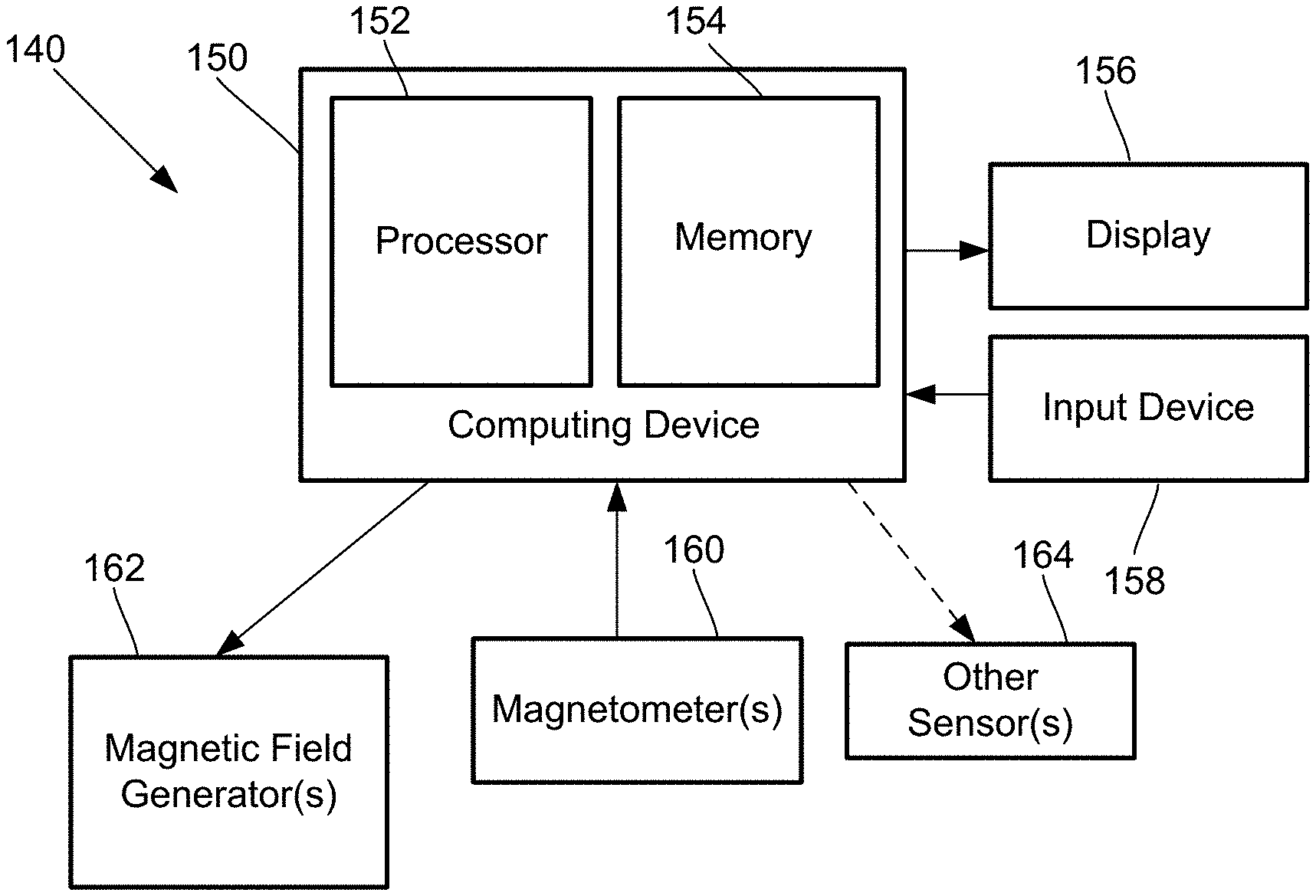
[0029] FIG. 1A is a block diagram of components of one embodiment of a magnetic field measurement system 140. The system 140 can include a computing device 150 or any other similar device that includes a processor 152 and a memory 154, a display 156, an input device 158, one or more magnetometers 160 (for example, an array of magnetometers) which can be OPMs, one or more magnetic field generators 162, and, optionally, one or more sensors 164. The system 140 and its use and operation will be described herein with respect to the measurement of neural signals arising from signal sources in the brain of a user as an example. It will be understood, however, that the system can be adapted and used to measure other neural signals, other biological signals, as well as non-biological signals.
[0030] The computing device 150 can be a computer, tablet, mobile device, field programmable gate array (FPGA), microcontroller, or any other suitable device for processing information or instructions. The computing device 150 can be local to the user or can include components that are non-local to the user including one or both of the processor 152 or memory 154 (or portions thereof). For example, in at least some embodiments, the user may operate a terminal that is connected to a non-local computing device. In other embodiments, the memory 154 can be non-local to the user.
[0031] The computing device 150 can utilize any suitable processor 152 including one or more hardware processors that may be local to the user or non-local to the user or other components of the computing device. The processor 152 is configured to execute instructions, as described below.
[0032] Any suitable memory 154 can be used for the computing device 150. The memory 154 illustrates a type of computer-readable media, namely computer-readable storage media. Computer-readable storage media may include, but is not limited to, volatile, nonvolatile, non-transitory, removable, and non-removable media implemented in any method or technology for storage of information, such as computer readable instructions, data structures, program modules, or other data. Examples of computer-readable storage media include RAM, ROM, EEPROM, flash memory, or other memory technology, CD-ROM, digital versatile disks ("DVD") or other optical storage, magnetic cassettes, magnetic tape, magnetic disk storage or other magnetic storage devices, or any other medium which can be used to store the desired information and which can be accessed by a computing device.
[0033] Communication methods provide another type of computer readable media; namely communication media. Communication media typically embodies computer-readable instructions, data structures, program modules, or other data in a modulated data signal such as a carrier wave, data signal, or other transport mechanism and include any information delivery media. The terms "modulated data signal," and "carrier-wave signal" includes a signal that has one or more of its characteristics set or changed in such a manner as to encode information, instructions, data, and the like, in the signal. By way of example, communication media includes wired media such as twisted pair, coaxial cable, fiber optics, wave guides, and other wired media and wireless media such as acoustic, RF, infrared, and other wireless media.
[0034] The display 156 can be any suitable display device, such as a monitor, screen, or the like, and can include a printer. In some embodiments, the display is optional. In some embodiments, the display 156 may be integrated into a single unit with the computing device 150, such as a tablet, smart phone, or smart watch. In at least some embodiments, the display is not local to the user. The input device 158 can be, for example, a keyboard, mouse, touch screen, track ball, joystick, voice recognition system, or any combination thereof, or the like. In at least some embodiments, the input device is not local to the user.
[0035] The magnetic field generator(s) 162 can be, for example, Helmholtz coils, solenoid coils, planar coils, saddle coils, electromagnets, permanent magnets, or any other suitable arrangement for generating a magnetic field. As an example, the magnetic field generator 162 can include three orthogonal sets of coils to generate magnetic fields along three orthogonal axes. Other coil arrangement can also be used. The optional sensor(s) 164 can include, but are not limited to, one or more magnetic field sensors, position sensors, orientation sensors, accelerometers, image recorders, or the like or any combination thereof.
[0036] The one or more magnetometers 160 can be any suitable magnetometer including, but not limited to, any suitable optically pumped magnetometer. In at least some embodiments, at least one of the one or more magnetometers (or all of the magnetometers) of the system is arranged for operation in the SERF mode. Examples of magnetic field measurement systems or methods of making such systems or components for such systems are described in U.S. patent application Ser. Nos. 16/213,980; 16/405,382; 16/418,478; 16/418,500; 16/428,871; 16/456,975; 16/457,655; 16/573,394; 16/573,524; 16/679,048; and 16/741,593, and U.S. Provisional Patent Applications Ser. Nos. 62/689,696; 62/699,596; 62/719,471; 62/719,475; 62/719,928; 62/723,933; 62/732,327; 62/732,791; 62/741,777; 62/743,343; 62/747,924; 62/745,144; 62/752,067; 62/776,895; 62/781,418; 62/796,958; 62/798,209; 62/798,330; 62/804,539; 62/826,045; 62/827,390; 62/836,421; 62/837,574; 62/837,587; 62/842,818; 62/855,820; 62/858,636; 62/860,001; 62/865,049; 62/873,694; 62/874,887; 62/883,399; 62/883,406; 62/888,858; 62/895,197; 62/896,929; 62/898,461; 62/910,248; 62/913,000; 62/926,032; 62/926,043; 62/933,085; and 62/960,548, all of which are incorporated herein by reference in their entireties.
[0037] FIG. 1B is a schematic block diagram of one embodiment of a magnetometer 160 which includes an alkali metal gas cell 170 (also referred to as a "cell" or "vapor cell"); a heating device 176 to heat the cell 170; a light source 172; and a detector 174. In addition, coils of a magnetic field generator 162 can be positioned around the vapor cell 170. The gas cell 170 can include, for example, an alkali metal vapor (for example, rubidium in natural abundance, isotopically enriched rubidium, potassium, or cesium, or any other suitable alkali metal such as lithium, sodium, or francium) and, optionally, one, or both, of a quenching gas (for example, nitrogen) and a buffer gas (for example, nitrogen, helium, neon, or argon). In some embodiments, the vapor cell may include the alkali metal atoms in a prevaporized form prior to heating to generate the vapor.
[0038] The light source 172 can include, for example, a laser to, respectively, optically pump the alkali metal atoms and to probe the vapor cell. The light source 172 may also include optics (such as lenses, waveplates, collimators, polarizers, and objects with reflective surfaces) for beam shaping and polarization control and for directing the light from the light source to the cell and detector. Examples of suitable light sources include, but are not limited to, a diode laser (such as a vertical-cavity surface-emitting laser (VCSEL), distributed Bragg reflector laser (DBR), or distributed feedback laser (DFB)), light-emitting diode (LED), lamp, or any other suitable light source. In some embodiments, the light source 172 may include two light sources: a pump light source and a probe light source.
[0039] The detector 174 can include, for example, an optical detector to measure the optical properties of the transmitted light field amplitude, phase, or polarization, as quantified through optical absorption and dispersion curves, spectrum, or polarization or the like or any combination thereof. Examples of suitable detectors include, but are not limited to, a photodiode, charge coupled device (CCD) array, CMOS array, camera, photodiode array, single photon avalanche diode (SPAD) array, avalanche photodiode (APD) array, or any other suitable optical sensor array that can measure the change in transmitted light at the optical wavelengths of interest.
[0040] FIG. 2 shows the magnetic spectrum from 1 fT to 100 .mu.T in magnetic field strength on a logarithmic scale. The magnitude of magnetic fields generated by the human brain are indicated by range 201 and the magnitude of the background ambient magnetic field, including the Earth's magnetic field, by range 202. The strength of the Earth's magnetic field covers a range as it depends on the position on the Earth as well as the materials of the surrounding environment where the magnetic field is measured. Range 210 indicates the approximate measurement range of a magnetometer (e.g., an OPM) operating in the SERF mode (e.g., a SERF magnetometer) and range 211 indicates the approximate measurement range of a magnetometer operating in a scalar mode (e.g., a scalar magnetometer.) Typically, a SERF magnetometer is more sensitive than a scalar magnetometer but many conventional SERF magnetometers typically only operate up to about 0 to 200 nT while the scalar magnetometer starts in the 10 to 100 fT range but extends above 10 to 100 .mu.T.
[0041] FIG. 2 also illustrates a challenge in measuring neural and other biological signals; namely the measurement of signals with a dynamic range of, for example, approximately 5.times.10.sup.9 which corresponds to the ratio of the amplitude of a neural signal (approximately 10 fT) to the amplitude of the Earth's magnetic field (approximately 50 .mu.T). Conventionally, MEG signals have been recorded by SQUIDs or optically pumped magnetometers (OPMs) inside large, immobile, and expensive magnetically shielded rooms. The magnetic shield isolates the subject from the Earth's magnetic field of around 50 .mu.T and suppresses a variety of environmental sources of noise. The magnetic shield also reduces the dynamic range used to measure small neural signals which are in the range of 10-100 fT. In the case of OPMs, spin-exchange relaxation-free (SERF) magnetometers that feature a narrow resonance (from 0 to 10-100 nT) centered on zero magnetic field have been used to demonstrate MEG. Outside of this range the atoms in the OPM lose sensitivity to magnetic fields.
[0042] These shielded rooms, however, are generally not viable for a consumer market where it is thought that magnetic field measurements systems for MEG should be able to operate in the ambient background magnetic field of the native environment, including the Earth's magnetic field and other local sources of magnetic fields. One additional conventional solution is to incorporate a feedback system to null magnetic fields at the OPM magnetometer operating in the SERF mode. In this arrangement, the current in the feedback coils becomes a measure of the magnetic field. This enables the SERF magnetometer to operate in finite magnetic fields, however it does not address the issue of measuring signals with a dynamic range of 5.times.10.sup.9.
[0043] In contrast to these conventional arrangements, a new arrangement circumvents the need for such high dynamic range by incorporating a low-pass filter into a feedback loop. Most environmental magnetic field noise and noise due to subject motion occurs at low frequencies (below approximately 10 Hz) and neural signals often occur at higher frequencies (above approximately 50 Hz). The ability of a feedback loop with a low pass filter to track low frequency fluctuations thus reduces the needed dynamic range in the frequency band of interest as the higher amplitude magnetic fields are filtered out due to their low frequency fluctuations. Furthermore, contrary to conventional arrangements that utilized auxiliary sensors (such as fluxgates) for zero-field finding, at least some embodiments of the present arrangements can incorporate the same OPM for zero-field finding which may reduce system cost and simplify its use.
[0044] In at least some embodiments, the arrangements described herein can enhance the dynamic range of optically pumped magnetometers (OPMs) in magnetic field measurements systems for magnetoencephalography (MEG) to facilitate applications, systems, and arrangements for use outside of magnetically shielded rooms. In at least some embodiments, an arrangement, device, or system as described herein can separate high-frequency neural signals (for example, above a pre-selected or user-defined cutoff frequency) from low frequency noise (in the band from continuous to the pre-selected or user-defined cutoff frequency) arising due to, for example, external field perturbations or user motion in an ambient background magnetic field.
[0045] The arrangements and their use and operation will be described herein with respect to the measurement of neural signals arising from signal sources in the brain of a user as an example. It will be understood, however, that these arrangements can be adapted and used to measure other neural signals, other biological signals, or other non-biological signals.
[0046] FIG. 3 illustrates one embodiment of an OPM arrangement 310 where two feedback loops are employed to reduce or zero the magnetic field in two directions based on a signal obtained from a single beam transmission mode magnetometer 360. In FIG. 3, the arrangement includes an optically pumped magnetometer 360 operating in closed loop mode to enable detection of weak, high-frequency neural signals on top of a much larger, slowly varying ambient background magnetic field. A light source 372, such as a laser, optically pumps a vapor cell 370. Laser light transmitted through the vapor cell 370 is monitored via a detector 374, such as a photodiode. A magnetic field generator 362 (for example, a set of feedback coils) is used to generate small magnetic field modulations (for example, 10 nT amplitude at 1 kHz) and to compensate for external magnetic field fluctuations. For example, the magnetic field generator 362 can include one set of feedback coils to compensate for magnetic field fluctuations in the x-direction and one set of feedback coils to compensate for the magnetic field fluctuations in the y-direction.
[0047] A demodulation and feedback circuit 314 receives the signal from the detector 374 and uses that signal for purposes including, but not limited to, 1) generation of the small magnetic field modulation using the magnetic field generator 362 to convert the vapor cell absorptive resonance (with respect to the magnetic field) into a dispersively shaped error signal in the first harmonic of the demodulated signal, and 2) to implement a feedback loop that can compensate for slowly varying ambient background magnetic field perturbations by running the appropriate quasi-static current through the magnetic field generator 362 to generate a magnetic field near the vapor cell 370.
[0048] The demodulation and feedback circuit 314 in FIG. 3 includes two feedback loops 316a, 316b for two directions (orthogonal directions "x" and "y" in the illustrated embodiment but any other suitable directions can be used.) Each feedback loop 316a, 316b includes a modulation source 317a, 317b. In at least some embodiments, the modulation frequency is higher than the estimated frequency of the signals to be detected such as neural signals. In at least some embodiments, the modulation frequency is at or above, for example, 100, 200, 250, 500, 1000 Hz or higher.
[0049] Each feedback loop 316a, 316b also includes a first low pass filter 318a, 318b with a cutoff frequency that passes the slow motions of many background ambient magnetic field variations but excludes the higher frequency neural signals. In the embodiment of FIG. 3, the first low pass filter is part of a proportional integral derivative (PID) element. As examples, the cutoff frequency for the low pass filter 318a, 318b of the PID element can be in the range of 5 to 40 Hz or in the range of 8 to 20 Hz or, for example, 5, 8, 10, 12, 15, 20, or 25 Hz. Since the low pass filter 318a, 318b of the PID element only passes low frequency signals to the magnetic field generator 362, high frequency neural signals originating from the brain remain in the demodulated first harmonic signal. Applications for such neural signals include, but are not limited to identification of cognitive processes, interfaces with computers, control of prosthetics, and the like. Examples of non-invasive magnetic field measurement applications systems or methods are described in U.S. patent application Ser. No. 16/364,338 and U.S. Provisional Patent Application Ser. Nos. 62/829,124; 62/894,578; and 62/891,128, all of which are incorporated herein by reference.
[0050] Each feedback loop may also include a second low pass filter 320a, 320b with a cutoff frequency higher than the frequency of the neural signals to be detected. This second low pass filter 320a, 320b may remove higher frequency magnetic field variations, as well as interference from the modulation frequency. The cutoff frequency is selected to be higher than the signals to be detected and may be lower than the modulation frequency. For example, the cutoff frequency can be at least 100, 150, 200, 250 Hz, 500 Hz, or more.
[0051] An output 322a, 322b between the low pass filter 320a, 320b and low pass filter 318a, 381b of the PID element provides the neural signal. In at least some embodiments, at the output 322a, 322b, the dispersively shaped error signal from the detector 374, as modified by the demodulation and feedback circuit 314, is linear with respect to the neural signals to be detected.
[0052] The arrangement illustrated in FIG. 3 utilizes a transmission mode SERF magnetometer and a single laser beam and is sensitive to only two components of magnetic field. Other embodiments can include two laser beams and are sensitive to three magnetic field components. In at least some of these embodiments, three separate feedback loops can be used. One such embodiment is illustrated in FIG. 4 with three feedback loops 316a, 316b, 316c. This arrangement 310 includes a probe laser 372, a pump laser 324, a vapor cell 370, detectors 374, a polarizing beamsplitter 326, and a magnetic field generator 362 with sets of feedback coils in all three orthogonal axes.
[0053] The demodulation and feedback circuit 314 in FIG. 4 includes three feedback loops 316a, 316b, 316c. Two of the feedback loops 316a, 316b includes a modulation source 317a, 317b. Each feedback loop 316a, 316b, 316c also includes a first low pass filter 318a, 318b, 318c with a cutoff frequency that passes the slow motions of many background ambient magnetic field variations but excludes the higher frequency neural signals. In the embodiment of FIG. 4, the first low pass filter is part of a proportional integral derivative (PID) element. As examples, the cutoff frequency for the low pass filter 318a, 318b, 318c of the PID element can be in the range of 5 to 40 Hz or in the range of 8 to 20 Hz or, for example, 5, 8, 10, 12, 15, 20, or 25 Hz.
[0054] Two of the feedback loops 316a, 316b may also include a second low pass filter 320a, 320b with a cutoff frequency higher than the frequency of the neural signals to be detected. This low pass filter 320a, 320b may remove higher frequency magnetic field variations, as well as interference from the modulation frequency. The cutoff frequency is selected to be higher than the signals to be detected and may be lower than the modulation frequency. An output 322a, 322b, 322c prior to the low pass filter 318a, 318b, 318c of the PID element provides the neural signal.
[0055] Magnetic field measurement systems involving superconducting quantum interference device magnetometers may also benefit from the feedback loop arrangements presented above.
[0056] Another embodiment utilizes more than one magnetometer in an array. FIG. 5 illustrates one embodiment of an array of magnetometers 560a, 560b, 560c, . . . 560n, the control signal from the feedback loop 514 (for example, the signal provided to the magnetic field generator 362 from the feedback loops 316a, 316b in FIG. 3) of the first magnetometer 560a may be used to correct the magnetic field of other OPMs 560b, 560c, . . . 560n in a local array. For example, the control signal from the feedback loop 514 can be provided to magnetic field generators of the magnetometers 560b, 560c, . . . 560n (or a single magnetic field generator for the entire array or magnetic field generators for multiple magnetometers). As examples, either of the arrangements in FIGS. 3 and 4 can be used for the first magnetometer 560a and the feedback loop 514 with the signals directed to the magnetic field generator 362 in FIGS. 3 and 4 also being directed to the other magnetometers 560b, 560c, . . . 560n. In at least some embodiments of this array configuration, the first magnetometer 560a may be different in sensitivity or dynamic range from the other magnetometers or may not be an OPM; for example, the first magnetometer could be a fluxgate or other magnetic field sensing device. In these embodiment, signals from the additional sensors can be used to generate magnetic field gradient information.
[0057] In at least some instances, the embodiments presented above can also be placed inside a shield, such as a wearable passively shielded enclosures or a shielded room, to reduce the ambient background magnetic field.
[0058] Examples of magnetic field measurement systems in which the embodiments presented above can be incorporated, and which present features that can be incorporated in the embodiments presented herein, are described in U.S. patent application Ser. Nos. 16/213,980; 16/405,382; 16/418,478; 16/418,500; 16/428,871; 16/456,975; 16/457,655; 16/573,394; 16/573,524; 16/679,048; and 16/741,593, and U.S. Provisional Patent Applications Ser. Nos. 62/689,696; 62/699,596; 62/719,471; 62/719,475; 62/719,928; 62/723,933; 62/732,327; 62/732,791; 62/741,777; 62/743,343; 62/747,924; 62/745,144; 62/752,067; 62/776,895; 62/781,418; 62/796,958; 62/798,209; 62/798,330; 62/804,539; 62/826,045; 62/827,390; 62/836,421; 62/837,574; 62/837,587; 62/842,818; 62/855,820; 62/858,636; 62/860,001; 62/865,049; 62/873,694; 62/874,887; 62/883,399; 62/883,406; 62/888,858; 62/895,197; 62/896,929; 62/898,461; 62/910,248; 62/913,000; 62/926,032; 62/926,043; 62/933,085; and 62/960,548, all of which are incorporated herein by reference in their entireties.
[0059] In at least some embodiments, a magnetic field measurement system or other system, arrangement, device, or method can incorporate a feedback control loop with a low frequency cut off to correct for user motion/movement without disrupting the recording/detection of neural signals.
[0060] In at least some embodiments, the arrangements described herein incorporate a slow feedback loop to suppress low frequency noise in the demodulated magnetometer signal. This enables a SERF magnetometer to operate in finite fields, such as those found outside shielded rooms, which is desirable for commercialization of a wearable device and may reduce the dynamic range to manageable levels for neural signals in a high pass band.
[0061] The above specification provides a description of the invention and its manufacture and use. Since many embodiments of the invention can be made without departing from the spirit and scope of the invention, the invention also resides in the claims hereinafter appended.
* * * * *
D00000
D00001
D00002
D00003
XML
uspto.report is an independent third-party trademark research tool that is not affiliated, endorsed, or sponsored by the United States Patent and Trademark Office (USPTO) or any other governmental organization. The information provided by uspto.report is based on publicly available data at the time of writing and is intended for informational purposes only.
While we strive to provide accurate and up-to-date information, we do not guarantee the accuracy, completeness, reliability, or suitability of the information displayed on this site. The use of this site is at your own risk. Any reliance you place on such information is therefore strictly at your own risk.
All official trademark data, including owner information, should be verified by visiting the official USPTO website at www.uspto.gov. This site is not intended to replace professional legal advice and should not be used as a substitute for consulting with a legal professional who is knowledgeable about trademark law.