Heat Exchanger and Refrigeration Cycle Apparatus
NAKAMURA; Shin ; et al.
U.S. patent application number 16/651704 was filed with the patent office on 2020-08-13 for heat exchanger and refrigeration cycle apparatus. The applicant listed for this patent is Mitsubishi Electric Corporation. Invention is credited to Tomoyuki HAYASHI, Akira ISHIBASHI, Tsuyoshi MAEDA, Shin NAKAMURA.
| Application Number | 20200256626 16/651704 |
| Document ID | / |
| Family ID | 66173590 |
| Filed Date | 2020-08-13 |


| United States Patent Application | 20200256626 |
| Kind Code | A1 |
| NAKAMURA; Shin ; et al. | August 13, 2020 |
Heat Exchanger and Refrigeration Cycle Apparatus
Abstract
A heat exchanger includes: a plate-like fin having one end and an other end in a first direction; and a first heat transfer tube and a second heat transfer tube that each extends through the fin and that are adjacent to each other in a second direction. A portion to which the fin and the first heat transfer tube are connected and a clearance portion that separates between the fin and the first heat transfer tube are disposed between the fin and the first heat transfer tube. The clearance portion is disposed at one end side in the first direction relative to an imaginary center line that passes through a center of the first heat transfer tube in a long side direction and that extends along a short side direction.
| Inventors: | NAKAMURA; Shin; (Tokyo, JP) ; MAEDA; Tsuyoshi; (Tokyo, JP) ; ISHIBASHI; Akira; (Tokyo, JP) ; HAYASHI; Tomoyuki; (Tokyo, JP) | ||||||||||
| Applicant: |
|
||||||||||
|---|---|---|---|---|---|---|---|---|---|---|---|
| Family ID: | 66173590 | ||||||||||
| Appl. No.: | 16/651704 | ||||||||||
| Filed: | October 16, 2017 | ||||||||||
| PCT Filed: | October 16, 2017 | ||||||||||
| PCT NO: | PCT/JP2017/037384 | ||||||||||
| 371 Date: | March 27, 2020 |
| Current U.S. Class: | 1/1 |
| Current CPC Class: | F25B 47/025 20130101; F28F 17/005 20130101; F28F 2275/04 20130101; F28F 1/022 20130101; F28F 1/02 20130101; F25B 2500/01 20130101; F28D 1/05391 20130101; F28B 9/08 20130101; F28B 9/005 20130101; F28D 2021/0068 20130101; F25B 13/00 20130101; F25B 39/028 20130101; F28F 1/325 20130101; F28F 1/32 20130101; F25B 39/04 20130101; F28F 2215/12 20130101; F28F 17/00 20130101; F25B 39/02 20130101; F28F 2265/14 20130101 |
| International Class: | F28F 1/32 20060101 F28F001/32; F25B 39/02 20060101 F25B039/02 |
Claims
1. A heat exchanger comprising: a plate-like fin having one end and an other end in a first direction; and a first heat transfer tube and a second heat transfer tube that each extend through the fin and that are adjacent to each other in a second direction crossing the first direction, wherein an outer shape of each of the first heat transfer tube and the second heat transfer tube in a cross section perpendicular to an extending direction of each of the first heat transfer tube and the second heat transfer tube is a flat shape having a long side direction and a short side direction, a first end portion of the first heat transfer tube located at the one end side is disposed at one side in the second direction relative to a second end portion of the first heat transfer tube located at the other end side, a third end portion of the second heat transfer tube located at the one end side is disposed at the one side in the second direction relative to a fourth end portion of the second heat transfer tube located at the other end side, a portion to which the fin and at least one of the first heat transfer tube and the second heat transfer tube are connected, and at least one clearance portion that separates between the fin and the at least one of the first heat transfer tube and the second heat transfer tube are disposed between the fin and the at least one of the first heat transfer tube and the second heat transfer tube, the at least one clearance portion is disposed at the one end side in the first direction relative to an imaginary center line that passes through a center of the first heat transfer tube in the long side direction and that extends along the short side direction, and wherein the at least one clearance portion is disposed to overlap with a first imaginary line segment that connects between the first heat transfer tube and the second heat transfer tube in a shortest distance and that is drawn at the most one end side in the first direction.
2. (canceled)
3. The heat exchanger according to claim 2, wherein a width of the fin on the first imaginary line segment is shorter than a width of the fin on the imaginary center line.
4. The heat exchanger according to claim 3, wherein a width of the clearance portion in a direction along the first imaginary line segment is the maximum on the first imaginary line segment.
5. The heat exchanger according to claim 1, wherein each of the first heat transfer tube and the second heat transfer tube has an upper flat surface and a lower flat surface disposed in parallel to be separated from each other in the short side direction, and a first surface and a second surface, the first surface connecting the upper flat surface to the lower flat surface at the one end side, the second surface connecting the upper flat surface to the lower flat surface at the other end side, and the first imaginary line segment passes through a boundary portion between the upper flat surface and the first surface of the first heat transfer tube.
6. The heat exchanger according to claim 5, wherein the at least one clearance portion faces the upper flat surface of the first heat transfer tube.
7. The heat exchanger according to claim 5, wherein the at least one clearance portion faces the lower flat surface of the second heat transfer tube.
8. The heat exchanger according to claim 6, wherein the at least one clearance portion is constituted of a plurality of the clearance portions, the plurality of clearance portions include a first clearance portion that faces the upper flat surface of the first heat transfer tube, and a second clearance portion that is disposed to be separated from the first clearance portion in a direction along the first imaginary line segment, and that faces the lower flat surface of the second heat transfer tube.
9. The heat exchanger according to claim 1, wherein a distance in the second direction between the first end portion of the first heat transfer tube and the fourth end portion of the second heat transfer tube is shorter than a distance in the second direction between the second end portion of the first heat transfer tube and the third end portion of the second heat transfer tube.
10. A refrigeration cycle apparatus comprising: the heat exchanger according to claim 1; and a fan configured to blow a heat exchanging fluid to the heat exchanger along the first direction, wherein the heat exchanger is disposed such that the one end of the fin is located at a windward side of the heat exchanging fluid and the second direction is along a gravity direction.
11. The heat exchanger according to claim 3, wherein each of the first heat transfer tube and the second heat transfer tube has an upper flat surface and a lower flat surface disposed in parallel to be separated from each other in the short side direction, and a first surface and a second surface, the first surface connecting the upper flat surface to the lower flat surface at the one end side, the second surface connecting the upper flat surface to the lower flat surface at the other end side, and the first imaginary line segment passes through a boundary portion between the upper flat surface and the first surface of the first heat transfer tube.
12. The heat exchanger according to claim 11, wherein the at least one clearance portion faces the upper flat surface of the first heat transfer tube.
13. The heat exchanger according to claim 11, wherein the at least one clearance portion faces the lower flat surface of the second heat transfer tube.
14. The heat exchanger according to claim 4, wherein each of the first heat transfer tube and the second heat transfer tube has an upper flat surface and a lower flat surface disposed in parallel to be separated from each other in the short side direction, and a first surface and a second surface, the first surface connecting the upper flat surface to the lower flat surface at the one end side, the second surface connecting the upper flat surface to the lower flat surface at the other end side, and the first imaginary line segment passes through a boundary portion between the upper flat surface and the first surface of the first heat transfer tube.
15. The heat exchanger according to claim 14, wherein the at least one clearance portion faces the upper flat surface of the first heat transfer tube.
16. The heat exchanger according to claim 14, wherein the at least one clearance portion faces the lower flat surface of the second heat transfer tube.
17. The heat exchanger according to claim 6, wherein the at least one clearance portion faces the lower flat surface of the second heat transfer tube.
18. The heat exchanger according to claim 7, wherein the at least one clearance portion is constituted of a plurality of the clearance portions, the plurality of clearance portions include a first clearance portion that faces the upper flat surface of the first heat transfer tube, and a second clearance portion that is disposed to be separated from the first clearance portion in a direction along the first imaginary line segment, and that faces the lower flat surface of the second heat transfer tube.
Description
CROSS REFERENCE TO RELATED APPLICATION
[0001] This application is a U.S. national stage application of International Application PCT/JP2017/037384, filed on Oct. 16, 2017, the contents of which are incorporated herein by reference.
TECHNICAL FIELD
[0002] The present invention relates to a heat exchanger and a refrigeration cycle apparatus, particularly, a fin and tube type heat exchanger and a refrigeration cycle apparatus including the fin and tube type heat exchanger.
BACKGROUND
[0003] Conventionally, there has been known a fin and tube type heat exchanger including: a plurality of plate-like fins arranged at a predetermined fin pitch interval; and a plurality of heat transfer tubes extending through the fins along a direction in which the plurality of fins are arranged.
[0004] In the fin and tube type heat exchanger, the plurality of heat transfer tubes are inserted in openings provided in the plurality of fins, such as through holes or notches. Accordingly, the plurality of heat transfer tubes extend through the fins. An end portion of each heat transfer tube is connected to a distribution tube or a header. Accordingly, a target heat exchanging fluid such as water or refrigerant flows in each heat transfer tube, and heat is exchanged between the target heat exchanging fluid and a heat exchanging fluid such as air flowing between the plurality of fins.
[0005] A conventional fin and tube type heat exchanger has been known in which each heat transfer tube has a flat cross sectional shape perpendicular to the extending direction of the heat transfer tube. With the heat transfer tube having such a flat cross sectional shape, separation of airflow can be reduced and airflow resistance can be smaller than that in a heat transfer tube having a circular cross sectional shape. Hence, the heat transfer tubes having such flat cross sectional shapes can be mounted in high density. A heat exchanger in which the heat transfer tubes each having a flat cross sectional shape are mounted in high density has an improved balance between heat transfer performance and airflow performance.
[0006] On the other hand, when the heat exchanger is operated as an evaporator in an environment in which an outdoor air temperature is, for example, below a freezing point, a water content in the heat exchanging fluid is condensed around the heat transfer tubes to result in frost. Such frost is melted into water droplets by a defrosting operation; however, the water droplets need to be appropriately discharged from around the heat transfer tubes in order to prevent accumulation and freezing of the water droplets around the heat transfer tubes.
[0007] In order to reduce a defrosting time by appropriately discharging water droplets from around heat transfer tubes, Japanese Patent Laying-Open No. 10-62086 discloses a fin and tube type heat exchanger in which a clearance for flow of water is formed between a lower surface of a heat transfer tube having a flat shape and an insertion hole in which the heat transfer tube is inserted.
PATENT LITERATURE
[0008] PTL 1: Japanese Patent Laying-Open No. 10-62086
[0009] However, in the conventional fin and tube type heat exchanger, a portion between adjacent heat transfer tubes cannot be sufficiently prevented from being blocked by frost, disadvantageously.
[0010] In the fin and tube type heat exchanger, the absolute humidity of the heat exchanging fluid flowing between the adjacent heat transfer tubes becomes smaller from a windward side to a leeward side in a flow direction. A temperature boundary layer formed between the adjacent heat transfer tubes becomes thicker from the windward side to the leeward side. Hence, in the conventional fin and tube type heat exchanger described in Japanese Patent Laying-Open No. 10-62086, frost is more likely to be formed at the windward side at which the absolute humidity of the heat exchanging fluid is large and the temperature boundary layer is thin, than at the leeward side at which the absolute humidity of the heat exchanging fluid is small and the temperature boundary layer is thick.
[0011] Particularly, when the heat transfer tubes are mounted in high density, a flow path for the heat exchanging fluid between the adjacent heat transfer tubes is likely to be blocked by frost grown at the windward side, disadvantageously. When the flow path for the heat exchanging fluid is blocked by frost, performance of the refrigeration cycle apparatus during a heating operation is decreased.
SUMMARY
[0012] A main object of the present invention is to provide a heat exchanger and a refrigeration cycle apparatus to effectively suppress a flow path for a heat exchanging fluid from being blocked by frost as compared with a conventional fin and tube type heat exchanger.
[0013] A heat exchanger according to the present invention includes: a plate-like fin having one end and an other end in a first direction; and a first heat transfer tube and a second heat transfer tube that each extend through the fin and that are adjacent to each other in a second direction crossing the first direction. An outer shape of each of the first heat transfer tube and the second heat transfer tube in a cross section perpendicular to an extending direction of each of the first heat transfer tube and the second heat transfer tube is a flat shape having a long side direction and a short side direction. A first end portion of the first heat transfer tube located at the one end side is disposed at one side in the second direction relative to a second end portion of the first heat transfer tube located at the other end side. A third end portion of the second heat transfer tube located at the one end side is disposed at the one side in the second direction relative to a fourth end portion of the second heat transfer tube located at the other end side. A portion to which the fin and at least one of the first heat transfer tube and the second heat transfer tube are connected, and at least one clearance portion that separates between the fin and the at least one of the first heat transfer tube and the second heat transfer tube are disposed between the fin and the at least one of the first heat transfer tube and the second heat transfer tube. The at least one clearance portion is disposed at the one end side in the first direction relative to an imaginary center line that passes through a center of the first heat transfer tube in the long side direction and that extends along the short side direction.
[0014] According to the present invention, by the clearance portion disposed to overlap with the first imaginary line, the temperature of the fin located on the first imaginary line during an operation as an evaporator is suppressed from being decreased as compared with a conventional heat exchanger. Hence, according to the present invention, there can be provided a heat exchanger and a refrigeration cycle apparatus to effectively suppress a flow path for a heat exchanging fluid from being blocked by frost.
BRIEF DESCRIPTION OF DRAWINGS
[0015] FIG. 1 shows an exemplary refrigerant circuit of a refrigeration cycle apparatus according to a first embodiment.
[0016] FIG. 2 is a perspective view showing an exemplary heat exchanger shown in FIG. 1.
[0017] FIG. 3 is a partial cross sectional view of the heat exchanger shown in FIG. 2.
[0018] FIG. 4 is a partial cross sectional view of the heat exchanger shown in FIG. 2.
[0019] FIG. 5 is a partial cross sectional view when seen from a line segment V-V in FIG. 4.
[0020] FIG. 6 is a partial cross sectional view showing a heat flux distribution of the heat exchanger shown in FIG. 3.
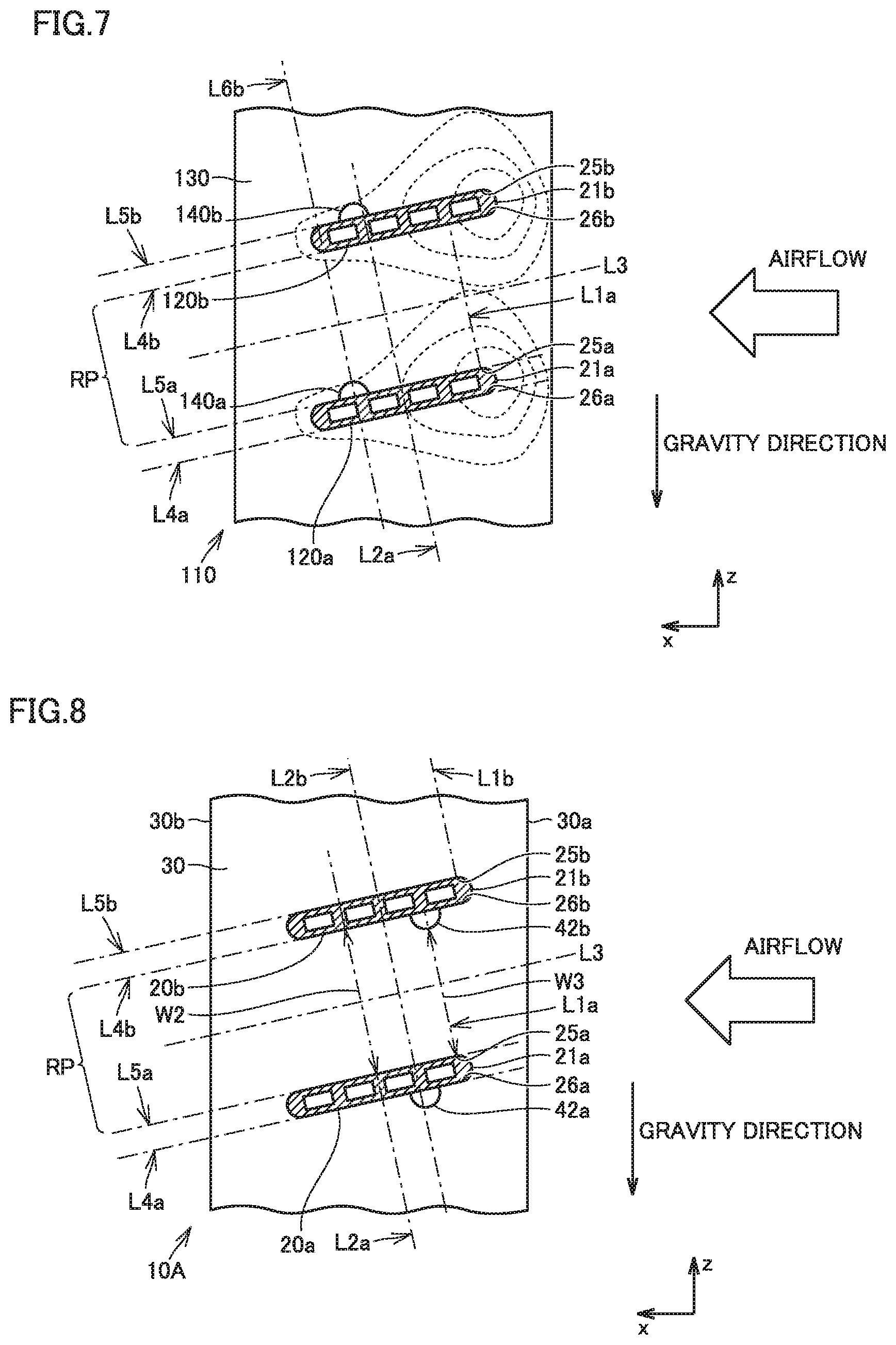
[0021] FIG. 7 is a partial cross sectional view showing a heat flux distribution of a comparative example.
[0022] FIG. 8 is a partial cross sectional view of a heat exchanger according to a second embodiment.
[0023] FIG. 9 is a partial cross sectional view of a heat exchanger according to a third embodiment.
[0024] FIG. 10 is a partial cross sectional view of a heat exchanger according to a fourth embodiment.
DETAILED DESCRIPTION
[0025] The following describes embodiments of the present invention with reference to figures. It should be noted that in the below-described figures, the same or corresponding portions are given the same reference characters and are not described repeatedly.
First Embodiment
[0026] <Configuration of Refrigeration Cycle Apparatus>
[0027] With reference to FIG. 1, a refrigeration cycle apparatus 1 according to a first embodiment will be described. As shown in FIG. 1, refrigeration cycle apparatus 1 includes a compressor 2, an indoor heat exchanger 3, an indoor fan 4, a throttle device 5, an outdoor heat exchanger 10, an outdoor fan 6, and a four-way valve 7. For example, compressor 2, outdoor heat exchanger 10, throttle device 5, and four-way valve 7 are provided in an outdoor unit, and indoor heat exchanger 3 is provided in an indoor unit.
[0028] Compressor 2, indoor heat exchanger 3, throttle device 5, outdoor heat exchanger 10, and four-way valve 7 constitute a refrigerant circuit in which refrigerant can circulate. In refrigeration cycle apparatus 1, a refrigeration cycle is performed in which the refrigerant circulates with a phase change in the refrigerant circuit.
[0029] Compressor 2 compresses the refrigerant. Compressor 2 is a rotary compressor, a scroll compressor, a screw compressor, a reciprocating compressor, or the like, for example.
[0030] Indoor heat exchanger 3 functions as a condenser during a heating operation, and functions as an evaporator during a cooling operation. Indoor heat exchanger 3 is a fin and tube type heat exchanger, a micro channel heat exchanger, a shell and tube type heat exchanger, a heat pipe type heat exchanger, a double-tube type heat exchanger, a plate heat exchanger, or the like, for example.
[0031] Throttle device 5 expands and decompresses the refrigerant. Throttle device 5 is an electrically powered expansion valve or the like that can adjust a flow rate of the refrigerant, for example. It should be noted that examples of throttle device 5 may include not only the electrically powered expansion valve but also a mechanical expansion valve employing a diaphragm for a pressure receiving portion, a capillary tube, or the like.
[0032] Outdoor heat exchanger 10 functions as an evaporator during the heating operation, and functions as a condenser during the cooling operation. Outdoor heat exchanger 10 is a fin and tube type heat exchanger. Details of outdoor heat exchanger 10 will be described later.
[0033] Four-way valve 7 can switch a flow path for the refrigerant in refrigeration cycle apparatus 1. During the heating operation, four-way valve 7 is switched to connect a discharge port of compressor 2 to indoor heat exchanger 3, and connect a suction port of compressor 2 to outdoor heat exchanger 10. Moreover, during the cooling operation and a dehumidification operation, four-way valve 7 is switched to connect the discharge port of compressor 2 to outdoor heat exchanger 10 and connect the suction port of compressor 2 to indoor heat exchanger 3.
[0034] Indoor fan 4 is attached to indoor heat exchanger 3 and supplies indoor air to indoor heat exchanger 3 as a heat exchanging fluid. Outdoor fan 6 is attached to outdoor heat exchanger 10 and supplies outdoor air to outdoor heat exchanger 10.
[0035] <Configuration of Heat Exchanger>
[0036] Next, heat exchanger 10 will be described with reference to FIG. 2 and FIG. 3.
[0037] It should be noted that in the description below, for ease of description, the x direction represents a direction in which a short side of each of a plurality of fins 30 included in heat exchanger 10 extends, the y direction represents a direction in which each of a plurality of heat transfer tubes 20 included in heat exchanger 10 extends, and the z direction (second direction) represents a direction in which a long side of each of the plurality of fins 30 included in heat exchanger 10 extends and in which the plurality of heat transfer tubes 20 are arranged and disposed to be separated from each other. In refrigeration cycle apparatus 1, heat exchanger 10 is disposed such that the x direction is along the flow direction of the heat exchanging fluid supplied from outdoor fan 6 shown in FIG. 1 and such that the z direction is along a gravity direction.
[0038] As shown in FIG. 2, heat exchanger 10 is a heat exchanger having a two-column structure, for example. Heat exchanger 10 includes: a first heat exchanger 11 disposed at a windward side in the x direction; and a second heat exchanger 12 disposed at a leeward side in the x direction. Each of first heat exchanger 11 and second heat exchanger 12 is configured as a fin and tube type heat exchanger. Each of first heat exchanger 11 and second heat exchanger 12 includes: a plurality of heat transfer tubes disposed to be separated from each other in the gravity direction; and a plurality of fins through which each of the plurality of heat transfer tubes extends. It should be noted that depending on a heat exchange load imposed on heat exchanger 10, heat exchanger 10 may be configured as a heat exchanger having a one-column structure, i.e., having one of first heat exchanger 11 and second heat exchanger 12.
[0039] As shown in FIG. 2, one end of each heat transfer tube of first heat exchanger 11 is connected to first header portion 13. One end of each heat transfer tube of second heat exchanger 12 is connected to second header portion 14. The other end of the heat transfer tube of first heat exchanger 11 and the other end of the heat transfer tube of second heat exchanger 12 are connected to an inter-column connection member 15.
[0040] First header portion 13 is provided to distribute externally supplied refrigerant to each of the heat transfer tubes of first heat exchanger 11. Second header portion 14 is provided to distribute externally supplied refrigerant to each of the heat transfer tubes of second heat exchanger 12. Accordingly, heat exchanger 10 has a refrigerant flow path in which first header portion 13, each heat transfer tube of first heat exchanger 11, inter-column connection member 15, each heat transfer tube of second heat exchanger 12, and second header portion 14 are connected in this order.
[0041] First heat exchanger 11 and second heat exchanger 12 have equivalent configurations, for example. In the description below, the configuration of first heat exchanger 11 will be described on behalf of first heat exchanger 11 and second heat exchanger 12.
[0042] As shown in FIG. 3 and FIG. 4, first heat exchanger 11 includes the plurality of heat transfer tubes 20 and the plurality of fins 30. Each of the plurality of heat transfer tubes 20 extends along the y direction. The plurality of heat transfer tubes 20 include a first heat transfer tube 20a and a second heat transfer tube 20b that are adjacent to each other in the z direction. First heat transfer tube 20a is disposed below second heat transfer tube 20b.
[0043] Each of the plurality of fins 30 is provided in a plate-like form. Each of the plurality of fins 30 has a surface that is perpendicular to the y direction and that has a rectangular outer shape, for example. When seen in the y direction, the short side of fin 30 is along the x direction, and the long side of fin 30 is along the z direction. Fin 30 has one end 30a and an other end 30b in the x direction. One end 30a is disposed at the windward side in the flow direction of the heat exchanging fluid, and other end 30b is disposed at the leeward side in the flow direction of the heat exchanging fluid. The plurality of fins 30 are provided with; through holes through which respective ones of the plurality of heat transfer tubes 20 extend; and clearance portions 41a, 41b continuous to the through holes (details will be described later). It should be noted that first heat transfer tube 20a and second heat transfer tube 20b shown in FIG. 3 are any two heat transfer tubes that are adjacent to each other in the gravity direction among the plurality of heat transfer tubes 20 in first heat exchanger 11. Fin 30 shown in FIG. 3 is any one fin of the plurality of fins 30 in first heat exchanger 11.
[0044] As shown in FIG. 3, the outer shape of each of first heat transfer tube 20a and second heat transfer tube 20b in the cross section perpendicular to the y direction is a flat shape having a long side direction and a short side direction orthogonal to the long side direction. Each of first heat transfer tube 20a and second heat transfer tube 20b has an upper flat surface and a lower flat surface disposed to be separated from each other in the short side direction. The upper flat surfaces and lower flat surfaces of first heat transfer tube 20a and second heat transfer tube 20b are disposed in parallel, for example. Each of first heat transfer tube 20a and second heat transfer tube 20b further has a first surface and a second surface, the first surface connecting the upper flat surface to the lower flat surface at the windward side, the second surface connecting the upper flat surface to the lower flat surface at the leeward side. In each of first heat transfer tube 20a and second heat transfer tube 20b, a plurality of flow paths for refrigerant to flow are disposed side by side in the long side direction of the flat shape, for example.
[0045] In the description below, for ease of description, a windward side end portion 21a (first end portion) represents an end portion of first heat transfer tube 20a located at the windward side (the one end 30a side of fin 30), and a leeward side end portion 22a (second end portion) represents an end portion of first heat transfer tube 20a located at the leeward side (the other end 30b side of fin 30). A first boundary portion 25a represents a boundary portion between the upper flat surface and first surface of first heat transfer tube 20a, and a second boundary portion 26a represents a boundary portion between the lower flat surface and first surface of first heat transfer tube 20a. A windward side end portion 21b (third end portion) represents an end portion of second heat transfer tube 20b located at the windward side, and a leeward side end portion 22b (fourth end portion) represents an end portion of second heat transfer tube 20b located at the leeward side. A third boundary portion 25b represents a boundary portion between the upper flat surface and first surface of second heat transfer tube 20b, and a fourth boundary portion 26b represents a boundary portion between the lower flat surface and first surface of second heat transfer tube 20b.
[0046] As shown in FIG. 3 and FIG. 4, windward side end portion 21a is disposed at the upper side relative to leeward side end portion 22a. Windward side end portion 21b is disposed at the upper side relative to leeward side end portion 22b. In other words, each of first heat transfer tube 20a and second heat transfer tube 20b is inclined downward in the gravity direction from the windward side to the leeward side in the flowing direction. From a different viewpoint, it can be said that a distance in the z direction between windward side end portion 21a of first heat transfer tube 20a and leeward side end portions 22b of second heat transfer tube 20b is shorter than a distance in the z direction between leeward side end portion 22a of first heat transfer tube 20a and windward side end portion 21b of second heat transfer tube 20b.
[0047] As shown in FIG. 3 and FIG. 4, in the cross section perpendicular to the y direction, each long side direction of first heat transfer tube 20a and second heat transfer tube 20b is disposed to form a smaller angle with respect to the x direction than an angle formed with respect to the z direction. In the cross section perpendicular to the y direction, each short side direction of first heat transfer tube 20a and second heat transfer tube 20b is disposed to form a larger angle with respect to the x direction than an angle formed with respect to the z direction. In the cross section perpendicular to the y direction, each long side direction of first heat transfer tube 20a and second heat transfer tube 20b forms an angle of less than or equal to 20.degree. with respect to the x direction, for example.
[0048] As shown in FIG. 3 and FIG. 4, windward side end portion 21a and windward side end portion 21b are disposed to overlap in the z direction. First boundary portion 25a and second boundary portion 26a are disposed to overlap in the short side direction. Third boundary portion 25b and fourth boundary portion 26b are disposed to overlap in the short side direction. Leeward side end portion 22a and leeward side end portion 22b are disposed to overlap in the z direction. First boundary portion 25a and third boundary portion 25b are disposed to overlap in the z direction.
[0049] As shown in FIG. 3, FIG. 4, and FIG. 5, first heat transfer tube 20a and second heat transfer tube 20b extend through each of of the plurality of fins 30. The plurality of fins 30 are disposed to be separated from each other at a predetermined interval FP (see FIG. 5) in the y direction.
[0050] As shown in FIG. 3, a first imaginary line segment 1a is defined to represent an imaginary line segment that extends along the short side direction, that passes through first boundary portion 25a and second boundary portion 26a, and that is located between first heat transfer tube 20a and second heat transfer tube 20b. An imaginary center line L2a is defined to represent an imaginary line that extends along the short side direction and that passes through the center of first heat transfer tube 20a in the long side direction. A second imaginary line segment L1b is defined to represent an imaginary line segment that extends along the short side direction, that passes through third boundary portion 25b and fourth boundary portion 26b, and that is located between third heat transfer tube 20c and second heat transfer tube 20b. Further, an imaginary line L3 is defined to represent an imaginary line that passes through the center between first heat transfer tube 20a and second heat transfer tube 20b in the short side direction and that extends along the long side direction. An imaginary line L4b is defined to represent an imaginary line obtained by extending the lower flat surface of second heat transfer tube 20b. An imaginary line L5a is defined to represent an imaginary line obtained by extending the upper flat surface of first heat transfer tube 20a. An imaginary line L5b is defined to represent an imaginary line obtained by extending the upper flat surface of second heat transfer tube 20b. An imaginary line L7 is defined to represent an imaginary line that connects windward side end portion 21a to windward side end portion 21b. An imaginary line L8 is defined to represent an imaginary line that connects leeward side end portion 22a to leeward side end portion 22b.
[0051] As shown in FIG. 4, an airflow path region RP is defined to represent a region which is located between first heat transfer tube 20a and second heat transfer tube 20b and in which the heat exchanging fluid flows along fin 30. In the y direction, airflow path region RP is disposed between imaginary line L7 that connects windward side end portion 21a to windward side end portion 21b and imaginary line L8 that connects leeward side end portion 22a to leeward side end portion 22b. A windward region RW is defined to represent a region that is disposed at the windward side relative to airflow path region RP, i.e., at the windward side relative to imaginary line L7 and that is continuous to airflow path region RP. A leeward region RL is defined to represent a region that is disposed at the leeward side relative to airflow path region RP, i.e., at the leeward side relative to imaginary line L8 and that is continuous to airflow path region RP. A second airflow path region RP2 is defined to represent a region which is disposed between second heat transfer tube 20b and third heat transfer tube 20c and in which the heat exchanging fluid flows. Airflow path region RP and second airflow path region RP2 are disposed with second heat transfer tube 20b being interposed therebetween.
[0052] As shown in FIG. 4, in airflow path region RP, a first region R1 is defined to represent a region in which first heat transfer tube 20a and second heat transfer tube 20b are connected in the shortest distance. First region R1 is a region disposed on fin 30 between imaginary line L5a obtained by extending the upper flat surface of first heat transfer tube 20a and imaginary line L4b obtained by extending the lower flat surface of second heat transfer tube 20b in the z direction, and between first imaginary line segment L1a and third imaginary line L6b in the flow direction. First region R1 has a rectangular shape. Further, in airflow path region RP, a second region R2 is defined to represent a region disposed between first region R1 and windward region RW, and a third region R3 is defined to represent a region disposed between first region R1 and leeward region RL.
[0053] As shown in FIG. 3, first imaginary line segment L1a is an imaginary line segment that connects between first heat transfer tube 20a and second heat transfer tube 20b in the shortest distance and that is drawn at the most windward side in the x direction. In other words, first imaginary line segment L1a is drawn at the most windward side on first region R1, and constitutes one side of first region R1. Second imaginary line segment L1b is an imaginary line segment that connects, in the shortest distance, between second heat transfer tube 20b and third heat transfer tube 20c disposed above second heat transfer tube 20b and adjacent to second heat transfer tube 20b. Second imaginary line segment L1b is an imaginary line segment drawn at the most windward side in the x direction. Imaginary center line L2a is an imaginary line that connects between first heat transfer tube 20a and second heat transfer tube 20b in the shortest distance and that is drawn at the leeward side relative to first imaginary line segment L1a. Imaginary center line L2a passes through the leeward side relative to the center of first region R1 in the long side direction. Each of the imaginary lines that connect between first heat transfer tube 20a and second heat transfer tube 20b in the shortest distance, such as first imaginary line segment L1a and imaginary center line L2a, is drawn on first region R1.
[0054] As shown in FIG. 3, in airflow path region RP, clearance portion 41a that separates between first heat transfer tube 20a and fin 30 is disposed at the windward side relative to imaginary center line L2a. Clearance portion 41a is disposed not to overlap with imaginary center line L2a. Clearance portion 41a is formed as a through hole extending through fin 30 in the y direction, for example. Clearance portion 41a may have any configuration as long as a heat path between first heat transfer tube 20a and fin 30 facing clearance portion 41a can be made longer than a heat path between first heat transfer tube 20a and fin 30 not facing clearance portion 41a. For example, clearance portion 41a may be configured as a portion depressed with respect to a plane perpendicular to the y direction in fin 30.
[0055] As shown in FIG. 3, clearance portion 41b is disposed at the windward side relative to imaginary center line L2b of second heat transfer tube 20b, for example. Clearance portion 41b is disposed not to overlap with imaginary center line L2b of second heat transfer tube 20b, for example.
[0056] As shown in FIG. 3, clearance portion 41a is disposed to overlap with first imaginary line segment L1a, for example. Clearance portion 41a faces a portion of each of the upper flat surface and first surface of first heat transfer tube 20a, for example. When seen in the y direction, clearance portion 41a is disposed to span first region R1 and second region R2, for example. That is, clearance portion 41a faces a portion of the upper flat surface of first heat transfer tube 20a located at the most windward side. It should be noted that when seen in the y direction, clearance portion 41a may be disposed to span first region R1, second region R2, and windward region RW, for example.
[0057] Although clearance portion 41a may have any planar shape when seen in the y direction, clearance portion 41a has a sector shape centering on a portion of first heat transfer tube 20a located on first imaginary line segment L1a, i.e., first boundary portion 25a as shown in FIG. 3, for example. The width of clearance portion 41a in the short side direction is the widest on first imaginary line segment L a, for example. The width of clearance portion 41a in the long side direction is the widest on imaginary line L5a, for example. In other words, the widest portion of clearance portion 41a in the long side direction is a portion of clearance portion 41a facing first heat transfer tube 20a, for example. The width of clearance portion 41a in the short side direction becomes gradually narrower as clearance portion 41a is further away from first imaginary line segment L1a in the long side direction, for example. The width of clearance portion 41a in the long side direction becomes gradually narrower as clearance portion 41a is further away from first heat transfer tube 20a in the short side direction, for example.
[0058] As shown in FIG. 3, since clearance portion 41a is disposed, a width W1 of fin 30 on first imaginary line segment L1a is shorter than width W2 of fin 30 on any imaginary line that connects between first heat transfer tube 20a and second heat transfer tube 20b in the shortest distance without clearance portion 41a being interposed therebetween in first region R1, such as imaginary center line L2a.
[0059] As shown in FIG. 3, width W1 of fin 30 on first imaginary line segment L1a is shorter than the width of fin 30 on any imaginary line that connects between first heat transfer tube 20a and second heat transfer tube 20b in the shortest distance in first region R1, such as an imaginary line that is located at the leeward side relative to first imaginary line segment L1a and that is drawn to overlap with clearance portion 41a.
[0060] As shown in FIG. 3, when seen in the y direction, the maximum width of clearance portion 41a is less than the width of first heat transfer tube 20a in the short side direction, for example. The length, in the long side direction, of a portion of the upper flat surface of first heat transfer tube 20a that faces clearance portion 41a is shorter than the length, in the long side direction, of a portion thereof that is located at the leeward side relative to the foregoing portion and that faces fin 30, for example.
[0061] As shown in FIG. 3, in second airflow path region RP2, clearance portion 41b that separates between second heat transfer tube 20b and fin 30 is disposed to overlap with second imaginary line segment L1b. Clearance portion 41b has the same configuration as that of clearance portion 41a. From a different viewpoint, it can be said that second heat transfer tube 20b has the same configuration as that of first heat transfer tube 20a with regard to a relation with third heat transfer tube 20c. Two adjacent heat transfer tubes in the gravity direction among the plurality of heat transfer tubes of first heat exchanger 11 have the same configurations as those of first heat transfer tube 20a and second heat transfer tube 20b. In first heat exchanger 11 shown in FIG. 3 and FIG. 4, the number of clearance portions disposed in one fin 30 is equal to the number of heat transfer tubes.
[0062] In each of the plurality of fins 30, clearance portions 41a, 41b such as those shown in FIG. 3 are disposed when fin 30 is seen in a plan view. Clearance portion 41a of one fin 30 is disposed to overlap with a clearance portion 41a of another fin 30 in the y direction. In other words, respective ones of the plurality of clearance portions disposed in one fin 30 are disposed to overlap with respective ones of the clearance portions disposed in the other fin 30 in the y direction. That is, in first heat exchanger 11, a plurality of groups of clearance portions are provided to be separated from each other in the z direction with each of the groups being constituted of a plurality of clearance portions disposed to overlap in the y direction.
[0063] As shown in FIG. 5, each of first heat transfer tube 20a and second heat transfer tube 20b is joined to fin 30 via a brazing material 33, except for a region facing clearance portion 41a or clearance portion 41b. Fin 30 has fin collar portions 32 provided around the through holes of fin 30 in which first heat transfer tube 20a and second heat transfer tube 20b are inserted. Each of fin collar portions 32 has a structure obtained by bending fin 30 with respect to a main plate portion 31 thereof having a surface perpendicular to the y direction. Fin collar portions 32 are also provided at regions facing clearance portions 41a, 41b. Fin collar portions 32 not facing clearance portions 41a, 41b are in contact with first heat transfer tube 20a and second heat transfer tube 20b, and a fillet is formed therebetween by brazing material 33. Accordingly, first heat transfer tube 20a and second heat transfer tube 20b are joined to fin 30 by way of the metal. A close contact area (joining area) between fin 30 and each of first heat transfer tube 20a and second heat transfer tube 20b is provided to be wide by way of the metal joining with brazing material 33, whereby excellent heat transfer can be attained therebetween. That is, heat transfer from first heat transfer tube 20a to fin 30 located on the above-described imaginary line (for example, imaginary center line L2a) that is located at the leeward side relative to first imaginary line segment L1a and that does not overlap with clearance portion 41a is performed efficiently in the shortest path.
[0064] On the other hand, fin collar portions 32 facing clearance portions 41a, 41b are disposed to be separated from first heat transfer tube 20a and second heat transfer tube 20b. They are not joined via brazing material 33. That is, no brazing material 33 is provided in clearance portion 41a between first heat transfer tube 20a and fin collar portion 32 on first imaginary line segment L1a. In clearance portion 41a, portions of the upper flat surface and first surface of first heat transfer tube 20a are exposed. Hence, heat transfer from first heat transfer tube 20a to fin 30 located on first imaginary line segment L1a via the shortest path is inhibited by clearance portion 41a.
[0065] Clearance portions 41a, 41b can be formed by any method, but are formed simultaneously with the forming of fin collar portions 32, for example. Moreover, clearance portions 41a, 41b can be used as regions in which bar-like brazing materials are disposed, when joining first heat transfer tube 20a and second heat transfer tube 20b to the plurality of fins 30. The bar-like brazing materials are prepared to correspond to the number of the clearance portions disposed on one fin 30, for example. The length of each bar-like brazing material in the extending direction is equal to the length of first heat exchanger 11 in the y direction, for example. Each bar-like brazing material is provided to be insertable in a group of clearance portions disposed to be continuous in the y direction. After the bar-like brazing material is inserted in the group of clearance portions, the bar-like brazing material is heated and melted to be permeated into a portion located between heat transfer tube 20 and fin 30 and disposed to be continuous to each clearance portion, i.e., into fin collar portion 32. Then, the brazing material is cooled to be solidified, whereby heat transfer tube 20 and fin 30 are joined firmly as shown in FIG. 5.
[0066] <Operations of Air Conditioner and Outdoor Heat Exchanger>
[0067] Next, operations of refrigeration cycle apparatus 1 and outdoor heat exchanger 10 will be described. Refrigeration cycle apparatus 1 is provided to perform the cooling operation, the heating operation, and the defrosting operation. In refrigeration cycle apparatus 1, each of the cooling operation and the defrosting operation, and the heating operation are switched by switching the refrigerant circuit by four-way valve 7. It should be noted that in FIG. 1, a broken line arrow represents a flow direction of the refrigerant during the cooling operation and the defrosting operation, and a solid line arrow represents a flow direction of the refrigerant during the heating operation.
[0068] During the cooling operation of refrigeration cycle apparatus 1, a refrigerant circuit is formed in which compressor 2, outdoor heat exchanger 10, throttle device 5, and indoor heat exchanger 3 are connected in this order. High-temperature and high-pressure single-phase gas refrigerant discharged from compressor 2 flows, via four-way valve 7, into outdoor heat exchanger 10 functioning as a condenser. In outdoor heat exchanger 10, heat exchange is performed between the high-temperature high-pressure gas refrigerant thus having flowed thereinto and air supplied by outdoor fan 6, whereby the high-temperature high-pressure gas refrigerant is condensed into single-phase high-pressure liquid refrigerant. The high-pressure liquid refrigerant sent out from outdoor heat exchanger 10 is formed, by throttle device 5, into two-phase state refrigerant including low-pressure gas refrigerant and liquid refrigerant. The two-phase state refrigerant flows into indoor heat exchanger 3 functioning as an evaporator. In indoor heat exchanger 3, heat exchange is performed between the two-phase state refrigerant thus having flowed thereinto and air supplied by indoor fan 4, whereby the liquid refrigerant of the two-phase state refrigerant is evaporated into single-phase low-pressure gas refrigerant. With this heat exchange, inside of a room is cooled. The low-pressure gas refrigerant sent out from indoor heat exchanger 3 flows into compressor 2 via four-way valve 7, is compressed into high-temperature high-pressure gas refrigerant, and is discharged again from compressor 2. Thereafter, this cycle is repeated.
[0069] During the heating operation of refrigeration cycle apparatus 1, a refrigerant circuit is formed in which compressor 2, indoor heat exchanger 3, throttle device 5, and outdoor heat exchanger 10 are connected in this order. High-temperature and high-pressure single-phase gas refrigerant discharged from compressor 2 flows, via four-way valve 7, into indoor heat exchanger 3 functioning as a condenser. In indoor heat exchanger 3, heat exchange is performed between the high-temperature high-pressure gas refrigerant thus having flowed thereinto and air supplied by indoor fan 4, whereby the high-temperature high-pressure gas refrigerant is condensed into single-phase high-pressure liquid refrigerant. With this heat exchange, inside of a room is heated. The high-pressure liquid refrigerant sent out from indoor heat exchanger 3 is formed, by throttle device 5, into two-phase state refrigerant including low-pressure gas refrigerant and liquid refrigerant. The two-phase state refrigerant flows into outdoor heat exchanger 10 functioning as an evaporator. In outdoor heat exchanger 10, heat exchange is performed between the two-phase state refrigerant thus having flowed thereinto and air supplied by outdoor fan 6, whereby the liquid refrigerant of the two-phase state refrigerant is evaporated into single-phase low-pressure gas refrigerant.
[0070] The low-pressure gas refrigerant sent out from outdoor heat exchanger 10 flows into compressor 2 via four-way valve 7, is compressed into high-temperature high-pressure gas refrigerant, and is discharged again from compressor 2. Thereafter, this cycle is repeated.
[0071] During the heating operation, a water content included in outdoor air is condensed by outdoor heat exchanger 10 functioning as an evaporator, whereby condensed water is generated on surfaces of the plurality of heat transfer tubes 20 and the plurality of plate-like fins 30. The condensed water falls down via the surfaces of heat transfer tubes 20 and fins 30, and is discharged to below the evaporator as drain water. Here, each of the plurality of heat transfer tubes 20 is inclined downward in the gravity direction from the windward side to the leeward side in the flow direction. Hence, the condensed water having reached the surfaces of heat transfer tubes 20 are efficiently discharged from outdoor heat exchanger 10. Furthermore, outdoor heat exchanger 10 has a high frost formation resistance (details will be described later).
[0072] However, part of the condensed water may become frost and the frost may be adhered to outdoor heat exchanger 10. The frost adhered to outdoor heat exchanger 10 inhibits heat exchange between the refrigerant and the outdoor air, with the result that the heating efficiency of refrigeration cycle apparatus 1 is decreased. Hence, refrigeration cycle apparatus 1 is provided to perform the defrosting operation for melting the frost adhered to outdoor heat exchanger 10.
[0073] During the defrosting operation of refrigeration cycle apparatus 1, the same refrigerant circuit as that during the cooling operation is formed. The refrigerant compressed in compressor 2 is sent to outdoor heat exchanger 10 to heat and melt the frost adhered to outdoor heat exchanger 10. Accordingly, the frost adhered to outdoor heat exchanger 10 during the heating operation is melted into water by the defrosting operation. The melt water is effectively discharged from outdoor heat exchanger 10. It should be noted that during the defrosting operation, indoor fan 4 and outdoor fan 6 are made non-operational, for example.
[0074] <Function and Effect>
[0075] Next, with reference to FIG. 6 and FIG. 7, the following describes function and effect of heat exchanger 10 based on a comparison with a comparative example. FIG. 6 is a partial enlarged view showing the configuration of heat exchanger 10 and a heat flux distribution representing an amount of exchanged heat per unit area on fin 30. FIG. 7 is a partial enlarged view showing a configuration of the comparative example and a heat flux distribution representing an amount of exchanged heat per unit area on a fin 130. Each of annular point lines shown in FIG. 6 and FIG. 7 indicates a heat flux contour line representing the amount of exchanged heat per unit area on the fin. It should be noted that since there is generally a correlation between heat transfer and mass transfer, it is considered that the heat flux has a correlation with an amount of mass transfer per unit area, i.e., mass flux indicating a local frost formation amount.
[0076] The heat exchanger of the comparative example shown in FIG. 7 is different from heat exchanger 10 in terms of the configuration of the clearance portion. In the comparative example, a clearance portion 140a that separates between a first heat transfer tube 120a and fin 30 is disposed to face an airflow path region between first heat transfer tube 120a and a second heat transfer tube 120b. Clearance portion 140a is disposed at the leeward side relative to imaginary center line L2a that passes through the center of first heat transfer tube 120a in the long side direction and that extends along the short side direction. Clearance portion 140a is provided as part of a discharge path for condensed water.
[0077] When the heat exchanger of the comparative example is operated as an evaporator, the temperature of the refrigerant serving as a target heat exchanging fluid is lower than the temperature of the air serving as a heat exchanging fluid. Therefore, the surface temperature of heat transfer tube 120a in which the refrigerant flows is lower than the surface temperature of fin 130 in the airflow path region through which the air flows. Since heat transfer between heat transfer tube 120a and fin 130 is performed from fin 130 to heat transfer tube 120a, the surface temperature of fin 130 indicates a distribution according to a distance between fin 130 and heat transfer tube 120a. Moreover, when flowing from the windward side to the leeward side via heat transfer tube 130 in which the refrigerant serving as a target heat exchanging fluid flows, the air is cooled and the water content in the air is condensed. Hence, the temperature and absolute humidity of the air supplied to the windward side in the fin and tube type heat exchanger is higher than the temperature and absolute humidity of the air passing at the leeward side.
[0078] By taking the above surface temperature distribution and the temperature and humidity distribution of the air into consideration, a heat flux (mass flux) distribution shown in FIG. 7 is found. In the comparative example shown in FIG. 7, first heat transfer tube 120a and fin 130 located at the windward side relative to imaginary center line L2a are connected in the shortest distance. Therefore, in the region located at the windward side relative to imaginary center line L2a, the heat flux contour line is disposed more densely and more widely from one of first heat transfer tube 120a and second heat transfer tube 120b to the other than that in the region located at the leeward side relative to imaginary center line L2a. Therefore, in the comparative example, a temperature difference between fin 130 and the air in the whole of the region located at the windward side relative to imaginary center line L2a and including imaginary line L3 becomes large to such an extent that frost is formed.
[0079] Particularly, on imaginary line L3, the temperature difference between fin 130 and the air is the maximum on first imaginary line segment L1a, i.e., the temperature difference therebetween is the maximum on an intersection between first imaginary line segment L1a and imaginary line L3. This is due to the following reason: fin 130 on the intersection is connected to first heat transfer tube 120a and second heat transfer tube 120b in the shortest distance and is therefore sufficiently cooled, whereas air having a comparatively high temperature is supplied onto the intersection to result in a large temperature difference between fin 130 and the air on the intersection.
[0080] Hence, in the comparative example, frost is likely to be formed also on imaginary line L3, with the result that airflow path region RP is likely to be blocked by the frost. Clearance portion 140a cannot sufficiently suppress such blocking. This makes it difficult for the heat exchanger of the comparative example to exhibit sufficient evaporation performance during the heating operation, thus resulting in decreased performance (heating performance) at the indoor unit side.
[0081] On the other hand, as shown in FIG. 6, heat exchanger 10 includes: plate-like fin 30; and first heat transfer tube 20a and second heat transfer tube 20b that each extend through fin 30 and that are adjacent to each other in the gravity direction. In the cross section perpendicular to the first direction in which first heat transfer tube 20a and second heat transfer tube 20b extend, the outer shape of each of first heat transfer tube 20a and second heat transfer tube 20b is a flat shape. First heat transfer tube 20a is disposed below second heat transfer tube 20b. The portion to which fin 30 and first heat transfer tube 20a are connected, and clearance portion 41a that separates between fin 30 and first heat transfer tube 20a are disposed between first heat transfer tube 20a and fin 30. Clearance portion 41a is disposed at the windward side in the flowing direction relative to imaginary center line L2a that passes through the center of first heat transfer tube 20a in the long side direction and that extends along the short side direction.
[0082] In heat exchanger 10 shown in FIG. 6, portions of first heat transfer tube 20a and fin 30 located at the windward side relative to imaginary center line L2a are connected to each other with clearance portion 41a being interposed therebetween, and the other portions thereof are connected directly to each other without clearance portion 41a being interposed therebetween. Therefore, a heat path between first heat transfer tube 20a and fin 30 connected to each other with clearance portion 41a being interposed therebetween becomes longer than a heat path between first heat transfer tube 20a and fin 30 connected directly to each other without clearance portion 41a being interposed therebetween. As a result, the heat flux contour line shown in FIG. 6 is depressed toward the first heat transfer tube 20a side at a region of fin 30 overlapping, in the short side direction, with clearance portion 41a disposed at the windward side relative to imaginary center line L2a. That is, according to heat exchanger 10, the temperature of fin 30 located at the windward side relative to imaginary center line L2a during its operation as an evaporator, particularly, the temperature of fin 30 overlapping with clearance portion 41a in the short side direction and located on imaginary line L3 can be higher than that in the comparative example. Accordingly, in heat exchanger 10, frost formation in airflow path region RP, particularly, frost formation on imaginary line L3 can be suppressed as compared with the comparative example. Hence, airflow path region RP can be suppressed from being blocked by the frost. As a result, heat exchanger 10 can exhibit sufficient evaporation performance during the heating operation, whereby performance (heating performance) at the indoor unit side can be suppressed from being decreased.
[0083] Further, in clearance portion 41a of heat exchanger 10, portions of the upper flat surface and first surface of first heat transfer tube 20a are exposed. Accordingly, according to heat exchanger 10, during its operation as an evaporator, frost can be intensively generated on the surfaces of first heat transfer tube 20a exposed in clearance portion 41a, whereby the flow path for the heat exchanging fluid can be suppressed more effectively from being blocked by frost.
[0084] Further, first heat transfer tube 20a and second heat transfer tube 20b are inclined such that leeward side end portions 22a. 22b are located at the lower side relative to windward side end portions 21a. 21b in the z direction. Accordingly, according to heat exchanger 10, for example, even when no air is supplied from outdoor fan 6 shown in FIG. 1 during the defrosting operation, water droplets adhered on the surfaces of first heat transfer tube 20a and second heat transfer tube 20b flow out to the leeward side due to gravity, and are discharged via the leeward region.
[0085] Accordingly, heat exchanger 10 has a high water discharging characteristic.
[0086] In heat exchanger 10, clearance portion 41a is disposed to overlap with the first imaginary line segment that connects between first heat transfer tube 20a and second heat transfer tube 20b in the shortest distance and that is drawn at the most windward side in the flowing direction.
[0087] Therefore, fin 30 and first boundary portion 25a of first heat transfer tube 20a located on first imaginary line segment L1a are connected with clearance portion 41a being interposed therebetween, and are therefore not connected to each other in the shortest distance. That is, heat transfer from first heat transfer tube 20a to fin 30 located on first imaginary line segment L1a is inhibited from being performed via the shortest path, by clearance portion 41a disposed to overlap with first imaginary line segment L1a. Accordingly, according to heat exchanger 10, the temperature of fin 30 located on first imaginary line segment L1a during its operation as an evaporator, such as the temperature of fin 30 located on the intersection between first imaginary line segment L1a and imaginary line L3, can be higher than that in the comparative example. As a result, in heat exchanger 10, as compared with the comparative example, the flow path for the heat exchanging fluid can be suppressed effectively from being blocked by frost.
[0088] In heat exchanger 10, the width of fin 30 on first imaginary line segment L1a is shorter than the width of fin 30 on imaginary center line L2a that connects between first heat transfer tube 20a and second heat transfer tube 20b in the shortest distance and that passes through the center of first heat transfer tube 20a. Fin 30 facing airflow path region RP and located at least on imaginary center line L2a is connected to first heat transfer tube 20a in the shortest distance. Accordingly, heat can be efficiently exchanged with first heat transfer tube 20a. That is, according to heat exchanger 10, sufficient heat exchanging performance can be secured while effectively suppressing the flow path for the heat exchanging fluid from being blocked by frost during its operation as an evaporator as compared with the conventional heat exchanger.
[0089] In heat exchanger 10, the width of clearance portion 41a in the direction along first imaginary line segment L1a is the maximum on first imaginary line segment L1a.
[0090] In this way, heat exchange between fin 30 and first heat transfer tube 20a on the region not overlapping with first imaginary line segment L a is not greatly inhibited by clearance portion 41a. Therefore, according to heat exchanger 10, sufficient heat exchanging performance can be secured while effectively suppressing the flow path for the heat exchanging fluid from being blocked by frost during its operation as an evaporator as compared with the conventional heat exchanger.
[0091] Each of first heat transfer tube 20a and second heat transfer tube 20b of heat exchanger 10 has: the upper flat surface and lower flat surface disposed in parallel to be separated from each other in the short side direction in the cross section; and the first surface and second surface, the first surface connecting the upper flat surface to the lower flat surface at the windward side, the second surface connecting the upper flat surface to the lower flat surface at the leeward side in the flowing direction. First imaginary line segment L1a passes through first boundary portion 25a between the upper flat surface and first surface of first heat transfer tube 20a. Clearance portion 41a faces the upper flat surface and first surface of first heat transfer tube 20a.
[0092] In this way, in a method for manufacturing heat exchanger 10, when clearance portion 41a is used as an insertion portion for the bar-like brazing material, the melted brazing material can be spread widely via the upper flat surface and can be spread widely via the first surface. As a result, a fillet can be uniformly formed using brazing material 33 around first heat transfer tube 20a.
[0093] Refrigeration cycle apparatus 1 includes: heat exchanger 10; and fan 6 configured to blow the heat exchanging fluid to heat exchanger 10. In such a refrigeration cycle apparatus 1, when heat exchanger 10 is used as an evaporator, heat exchanger 10 can exhibit high evaporation performance as described above. Hence, higher heating performance can be exhibited than that in a refrigeration cycle apparatus including the heat exchanger of the comparative example.
[0094] From a viewpoint that does not take into consideration a manner in which heat exchanger 10 is disposed within refrigeration cycle apparatus 1, it can be said that the first end portion (windward side end portion 21a) of first heat transfer tube 20a located at the one end 30a side of fin 30 in the x direction is disposed at the one side in the z direction relative to the second end portion (leeward side end portion 22a) of first heat transfer tube 20a located at the other end 30b side of fin 30 in the x direction. The third end portion (windward side end portion 21b) of second heat transfer tube 20b located at the one end 30a side in the x direction is disposed at the one side in the z direction relative to the fourth end portion (leeward side end portion 22b) located at the other end 30b side of fin 30 in the x direction. The distance in the z direction between the first end portion (windward side end portion 21a) of first heat transfer tube 20a and the fourth end portion (leeward side end portion 22b) of second heat transfer tube 20b is shorter than the distance in the z direction between the second end portion (leeward side end portion 22a) of first heat transfer tube 20a and the third end portion (windward side end portion 21b) of second heat transfer tube 20b. In the x direction, clearance portion 41a is disposed at the one end 30a side relative to imaginary center line L2a that passes through the center of first heat transfer tube 20a in the long side direction and that extends along the short side direction.
[0095] As described above, heat exchanger 10 serving as an outdoor heat exchanger in refrigeration cycle apparatus 1 is disposed such that: the x direction is along the direction of flow of the heat exchanging fluid caused by outdoor fan 6; one end 30a of fin 30 in the x direction is disposed at the windward side of the heat exchanging fluid, and the z direction is along the gravity direction. Accordingly, the first end portion of first heat transfer tube 20a and the third end portion of second heat transfer tube 20b are disposed at the windward side and serve as windward side end portions 21a, 21b, and the second end portion of first heat transfer tube 20a and the fourth end portion of second heat transfer tube 20b are disposed at the leeward side, and serve as leeward side end portions 22a, 22b. Further, first heat transfer tube 20a is disposed below second heat transfer tube 20b.
Second Embodiment
[0096] As shown in FIG. 8, a heat exchanger 10A according to a second embodiment includes basically the same configuration as that of heat exchanger 10 according to the first embodiment, but is different therefrom in that a clearance portion 42b provided to face airflow path region RP faces the lower flat surface of second heat transfer tube 20b.
[0097] Clearance portion 42b faces only the lower flat surface of the surfaces of second heat transfer tube 20b, for example. Clearance portion 42b does not face the first surface of second heat transfer tube 20b, for example. Although clearance portion 42b may have any planar shape when seen in the y direction, clearance portion 42b has a sector shape centering on a portion of second heat transfer tube 20b located on first imaginary line segment L1a as shown in FIG. 8, for example. Clearance portion 42b is provided in line symmetry with respect to first imaginary line segment L1a in the long side direction, for example.
[0098] As shown in FIG. 8, since clearance portion 42b is disposed, width W3 of fin 30 on first imaginary line segment L1a is shorter than width W2 of fin 30 on any imaginary line that connects between first heat transfer tube 20a and second heat transfer tube 20b in the shortest distance without clearance portion 42b being interposed therebetween in first region R1, such as imaginary center line L2a.
[0099] A clearance portion 42a facing the lower flat surface of first heat transfer tube 20a includes the same configuration as that of clearance portion 42b. Clearance portion 42a is disposed at the windward side relative to an imaginary center line of another heat transfer tube (not shown) disposed adjacent to first heat transfer tube 20a at a lower position in the gravity direction, and is disposed to overlap with a first imaginary line in the other heat transfer tube. Clearance portion 42a is disposed at the windward side relative to imaginary center line L2a of first heat transfer tube 20a, for example. Clearance portion 42a is disposed to overlap with imaginary center line L2b of second heat transfer tube 20b, for example.
[0100] According to such a heat exchanger 10A, clearance portion 42b is disposed at the windward side relative to imaginary center line L2a in airflow path region RP, and is also disposed to overlap with first imaginary line segment L1a. Hence, the same effect as that of heat exchanger 10 can be exhibited. That is, in heat exchanger 10A, as compared with the comparative example shown in FIG. 7, the flow path for the heat exchanging fluid can be suppressed effectively from being blocked by frost.
Third Embodiment
[0101] As shown in FIG. 9, a heat exchanger 10B according to a third embodiment includes basically the same configuration as those of heat exchanger 10 according to the first embodiment and heat exchanger 10A according to the second embodiment, but is different therefrom in that a clearance portion 43b provided to face airflow path region RP is not disposed to overlap with first imaginary line segment L1a and is disposed at the windward side relative to first imaginary line segment L1a.
[0102] Clearance portion 43b is disposed to overlap with second imaginary line segment L1b, for example. Clearance portion 43b faces the lower flat surface of second heat transfer tube 20b and the first surface of second heat transfer tube 20b, for example. Although clearance portion 43b may have any planar shape when seen in the y direction, clearance portion 43b has a sector shape centering on a portion of second heat transfer tube 20b located on first imaginary line segment L1a, i.e., fourth boundary portion 26b as shown in FIG. 9, for example.
[0103] A clearance portion 43a facing the lower flat surface of first heat transfer tube 20a includes the same configuration as that of clearance portion 43b. Clearance portion 43a is disposed at the windward side relative to a first imaginary center line of another heat transfer tube (not shown) disposed adjacent to first heat transfer tube 20a at a lower position in the gravity direction, and is disposed to overlap with a first imaginary line segment L1a of first heat transfer tube 20a.
[0104] According to such a heat exchanger 10B, clearance portion 43b is disposed at the windward side relative to imaginary center line L2a in airflow path region RP, and is also disposed to overlap with first imaginary line segment L1a. Hence, the same effect as that of heat exchanger 10 can be exhibited. That is, in heat exchanger 10B, as compared with the comparative example shown in FIG. 7, the flow path for the heat exchanging fluid can be suppressed effectively from being blocked by frost.
Fourth Embodiment
[0105] As shown in FIG. 10, a heat exchanger 10C according to a fourth embodiment includes basically the same configuration as that of heat exchanger 10 according to the first embodiment, but is different therefrom in that a plurality of clearance portions (a first clearance portion 44a and a second clearance portion 45b) are disposed in one airflow path region RP.
[0106] The plurality of clearance portions include: first clearance portion 44a that faces the upper flat surface of first heat transfer tube 20a; and second clearance portion 45b that is disposed to be separated from first clearance portion 44a in the short side direction and that faces the lower flat surface of second heat transfer tube 20b.
[0107] First clearance portion 44a includes the same configuration as that of clearance portion 41a shown in FIG. 3. Second clearance portion 45b includes the same configuration as that of clearance portion 42b shown in FIG. 8. First clearance portion 44a and second clearance portion 45b are disposed to be separated from each other in the short side direction. First clearance portion 44a and second clearance portion 45b are disposed to overlap with first imaginary line segment L1a.
[0108] As shown in FIG. 10, since clearance portion 41a is disposed, width W4 of fin 30 on first imaginary line segment L1a is shorter than width W2 of fin 30 on any imaginary line that connects between first heat transfer tube 20a and second heat transfer tube 20b in the shortest distance without first clearance portion 44a and second clearance portion 45b being interposed therebetween in first region R1, such as imaginary center line L2a. Width W4 is shorter than width W1 in heat exchanger 10 shown in FIG. 3 by the width of second clearance portion 45b in the short side direction.
[0109] Moreover, width W4 is shorter than width W3 in heat exchanger 10 shown in FIG. 8 by the width of first clearance portion 44a in the short side direction. Fin 30 on the intersection between first imaginary line segment L1a and imaginary line L3 is connected to first heat transfer tube 20a with first clearance portion 44a being interposed therebetween, and is connected to second heat transfer tube 20b with second clearance portion 45b being interposed therebetween.
[0110] In another airflow path region adjacent to airflow path region RP with first heat transfer tube 20a being interposed therebetween, a second clearance portion 45a facing the lower flat surface of first heat transfer tube 20a is disposed. As shown in FIG. 10, first clearance portion 44a facing the upper flat surface of first heat transfer tube 20a and second clearance portion 45a facing the lower flat surface of first heat transfer tube 20a are disposed not to overlap with each other in the short side direction, for example. It should be noted that respective portions of first clearance portion 44a and second clearance portion 45a may be disposed to overlap with each other in the short side direction.
[0111] Clearance portion 44b includes the same configuration as that of clearance portion 41b shown in FIG. 3. Clearance portion 45a includes the same configuration as that of clearance portion 42a shown in FIG. 8.
[0112] According to such a heat exchanger 10C, since first clearance portions 44a, 44b including the same configurations as those of clearance portions 41a, 41b of heat exchanger 10 and clearance portions 45a, 45b including the same configurations as those of clearance portions 42a, 42b of heat exchanger 10A are provided, the same effects as those of heat exchanger 10 and heat exchanger 10A can be exhibited.
[0113] Further, according to heat exchanger 10C, fin 30 on the intersection between first imaginary line segment L1a and imaginary line L3 is connected to first heat transfer tube 20a with first clearance portion 44a being interposed therebetween, and is connected to second heat transfer tube 20b with second clearance portion 45b being interposed therebetween. Accordingly, according to heat exchanger 10C, frost can be suppressed from being adhered to fin 30 on the intersection as compared with heat exchangers 10, 10A, whereby the flow path for the heat exchanging fluid can be suppressed more effectively from being blocked by frost.
[0114] Although the embodiments of the present invention have been illustrated as described above, the above-described embodiments can be modified in various manners.
[0115] Moreover, the scope of the present invention is not limited to the above-described embodiments. The scope of the present invention is defined by the terms of the claims, and is intended to include any modifications within the scope and meaning equivalent to the terms of the claims.
* * * * *
D00000
D00001
D00002
D00003
D00004
D00005
D00006
XML
uspto.report is an independent third-party trademark research tool that is not affiliated, endorsed, or sponsored by the United States Patent and Trademark Office (USPTO) or any other governmental organization. The information provided by uspto.report is based on publicly available data at the time of writing and is intended for informational purposes only.
While we strive to provide accurate and up-to-date information, we do not guarantee the accuracy, completeness, reliability, or suitability of the information displayed on this site. The use of this site is at your own risk. Any reliance you place on such information is therefore strictly at your own risk.
All official trademark data, including owner information, should be verified by visiting the official USPTO website at www.uspto.gov. This site is not intended to replace professional legal advice and should not be used as a substitute for consulting with a legal professional who is knowledgeable about trademark law.