System And Method For The Advanced Control Of Nitrogen Oxides In Waste To Energy Systems
Lucas; Jean ; et al.
U.S. patent application number 16/274946 was filed with the patent office on 2020-08-13 for system and method for the advanced control of nitrogen oxides in waste to energy systems. This patent application is currently assigned to ECO BURN INC.. The applicant listed for this patent is ECO BURN INC.. Invention is credited to Kim Docksteader, Jean Lucas, Jun Xiao.
| Application Number | 20200256559 16/274946 |
| Document ID | / |
| Family ID | 71946010 |
| Filed Date | 2020-08-13 |
| United States Patent Application | 20200256559 |
| Kind Code | A1 |
| Lucas; Jean ; et al. | August 13, 2020 |
SYSTEM AND METHOD FOR THE ADVANCED CONTROL OF NITROGEN OXIDES IN WASTE TO ENERGY SYSTEMS
Abstract
The present embodiments provide an incinerator which includes a system for reducing NOx and CO emissions. A computational fluid dynamics module is configured to generate a plurality of models related to a plurality of incinerator parameters. A programmable logic controller dynamically maintains a plurality of set points. Further, the programmable logic controller receives a plurality of output signals from a plurality of sensors and compares the plurality of output signals with the plurality of set points. The programmable logic controller is further to affect an amount of above-fire combustion air, an amount of under-fire combustion air, and an amount of above-fire and under-fire flue gas recirculation to reduce NOx emissions produced by the incinerator.
| Inventors: | Lucas; Jean; (Brlington, CA) ; Xiao; Jun; (Burlington, CA) ; Docksteader; Kim; (Burlington, CA) | ||||||||||
| Applicant: |
|
||||||||||
|---|---|---|---|---|---|---|---|---|---|---|---|
| Assignee: | ECO BURN INC. Burlington CA |
||||||||||
| Family ID: | 71946010 | ||||||||||
| Appl. No.: | 16/274946 | ||||||||||
| Filed: | February 13, 2019 |
| Current U.S. Class: | 1/1 |
| Current CPC Class: | F23G 2201/101 20130101; F23G 5/50 20130101; F23G 2207/101 20130101; F23G 2207/103 20130101; F23N 2223/40 20200101; F23G 2900/50001 20130101; F23G 2207/30 20130101; F23G 2900/55003 20130101; F23N 5/006 20130101; F23G 2207/105 20130101; F23N 5/003 20130101; F23G 2900/00001 20130101; F23G 2207/60 20130101; F23G 2207/104 20130101; F23C 9/00 20130101 |
| International Class: | F23G 5/50 20060101 F23G005/50 |
Claims
1. An incinerator having a system for reducing NOx and CO emissions, the system comprising: a computational fluid dynamics module configured to generate a plurality of models related to a plurality of incinerator parameters; a programmable logic controller in operable communication with a plurality of sensors to dynamically maintain a plurality of set points, the programmable logic controller receiving a plurality of output signals from a plurality of sensors, comparing the plurality of output signals with the plurality of set points, the programmable logic controller configured to effect an amount of above-fire combustion air, an amount of under-fire combustion air, and an amount of under-fire and above-fire flue gas recirculation to reduce NOx emissions produced by the incinerator.
2. The system of claim 1, wherein the incinerator further comprises a primary combustion chamber configured to receive waste materials from a loader to produce an amount of partially combusted waste materials.
3. The system of claim 2, further comprising a secondary combustion chamber in communication with the primary combustion chamber, the secondary combustion chamber configured to receive the amount of partially combusted waste materials, the secondary combustion chamber configured to produce substantially combusted waste materials and an amount of oxidized flue gas.
4. The system of claim 3, further comprising a heat recovery system in communication with the secondary combustion chamber, the heat recovery system configured to receive the substantially combusted waste materials for transfer to a cyclone.
5. The system of claim 4, wherein the cyclone filters precipitates from the oxidized flue gas, wherein the oxidized flue gas is recirculated to the secondary combustion chamber.
6. The system of claim 1, wherein the plurality of sensors includes at least one of the following: at least one oxygen sensor, at least one temperature sensor, at least one NOx sensor, and at least one CO sensor.
7. The system of claim 1, wherein the amount of above-fire combustion air and the amount of under-fire combustion air are controlled by one or more combustion air dampers, and wherein the amount of under-fire and above-fire flue gas is controlled by one or more flue gas dampers.
8. The system of claim 7, wherein the amount of above-fire combustion air and the amount of under-fire combustion each have an oxygen content of about 21%.
9. The system of claim 1, further comprising a plurality of injection nozzles positioned in the primary combustion chamber and the secondary combustion chamber, wherein the plurality of injection nozzles is dynamically configured via the programmable logic controller to adjust an angle of injection.
10. An incinerator having a system for reducing NOx and CO emissions, the system comprising: a primary combustion chamber configured to receive waste materials from a loader, the primary combustion chamber is configured to receive dynamically, via a programmable logic controller in operable communication with a plurality of sensors, an amount of above-fire combustion air, an amount of under-fire combustion air, and an amount of above-fire and under-fire flue gas recirculation to produce partially combusted waste materials; a secondary chamber configured to receive the partially combusted waste materials from the primary chamber, the secondary chamber further configured to dynamically receive, via the programmable logic controller, an amount of a reagent, an amount of above-fire primary recirculated flue gas, and an amount of secondary recirculation flue gas to produce substantially combusted waste materials and an amount of oxidized flue gas to reduce NOx emissions from the incinerator; a heat recovery system configured to receive an amount of the substantially combusted waste materials and the amount of oxidized flue gas; a cyclone configured to filter precipitates from the oxidized flue gas and to transfer the secondary flue gas to the secondary chamber; an air pollution control system and a stack to emit gas from the incinerator.
11. The system of claim 10, wherein the PLC is further configured to generates a plurality of models related to a plurality of incinerator parameters.
12. The system of claim 11, further comprising a plurality of injection nozzles positioned in the primary combustion chamber and the secondary combustion chamber, wherein the plurality of injection nozzles is configured via the programmable logic controller to adjust an angle of injection.
13. The system of claim 10, wherein the plurality of sensors each provide an output signal to the programmable logic controller, wherein the plurality of sensors include at least one of the following: at least one oxygen sensor, at least one temperature sensor, at least one NOx sensor, and at least one CO sensor.
14. The system of claim 10, wherein the at least one output signal provided by each of the plurality of sensors effects the amount of above-fire combustion air, the amount of under-fire combustion air, and the amount of above-fire and under-fire flue gas recirculation.
15. The system of claim 14, wherein the amount of above-fire combustion air and the amount of under-fire combustion air are controlled by one or more combustion air dampers, and wherein the amount of above-fire and under-fire flue gas is controlled by one or more flue gas dampers.
16. The system of claim 15, wherein the amount of above-fire combustion air and the amount of under-fire combustion air each have an oxygen content of about 21%.
17. A method for controlling NOx and CO emissions of an incinerator, the method comprising the steps of: modeling, via a computational fluid dynamics module, a plurality of emission outputs; determining an efficient model to reduce NOx and CO emissions; measuring, via a plurality of sensors, incinerator parameters; comparing, via the programmable logic controller, the incinerator parameters to a plurality of set points corresponding to the efficient model; and controlling, via the programmable logic controller, an amount of above-fire combustion air, an amount of under-fire combustion air, and an amount of above-fire and under-fire flue gas recirculation to reduce emissions of NOx and CO from the incinerator.
18. The method of claim 17, wherein the plurality of sensors include at least one of the following: at least one oxygen sensor, at least one temperature sensor, at least one NOx sensor, and at least one CO sensor.
19. The method of claim 17, wherein the amount of above-fire combustion air and the amount of under-fire combustion air are controlled by one or more combustion air dampers, and wherein the amount of under-fire and above fire flue gas is controlled by one or more flue gas dampers.
20. The method of claim 18, wherein the amount of above-fire combustion air and the amount of under-fire combustion air each have an oxygen content of about 21%.
Description
TECHNICAL FIELD
[0001] The embodiments relate to the reduction of chemical waste in combustion chambers, and in particular, to a system and method for reducing nitrogen oxides during the combustion of waste in a waste-to-energy system.
BACKGROUND
[0002] Traditional incinerators have been used in the United States since the early 19.sup.th century and were initially constructed to convert waste materials into ash, flue gas, and waste heat by combusting organic substances within a loaded waste material. These initial forms of incineration released harmful gaseous compounds and particulates directly into the environment without prior "scrubbing." When emitted into the air, fine particulates, heavy metals, trace dioxin, and acid gas were later inhaled by third-parties.
[0003] Today waste incineration and the inability to properly handle ash and heavy metals remain dangerous to the environment and toxic to humans. In response to this hazard, lobbying has led to a new generation of cleaner waste-to-energy innovation. Included within these innovations are systems which incorporate thermal and non-thermal applications including advanced incinerator, gasification, and pyrolysis which can convert gaseous effluents into electrical energy.
[0004] Combustion at high temperatures can generate nitrogen oxides (often referred to as NOx). NOx may be formed by the reaction of free radicals of nitrogen and oxygen in the air, as well as by the oxidation of nitrogen-containing species in the fuel such as those that may be found in heavy fuel oil, municipal waste solids, and coal.
[0005] Previous treatments for NOx have included various chemical or catalytic methods. Such methods include, for example, nonselective catalytic reduction (NSCR), selective catalytic reduction (SCR), and selective noncatalytic reduction (SNCR). Such methods typically require some type of reactant for removal of NOx emissions. The NSCR method can involve using unburned hydrocarbons and CO to reduce NOx emissions in the absence of O2.
SUMMARY OF THE INVENTION
[0006] This summary is provided to introduce a variety of concepts in a simplified form that is further disclosed in the detailed description. This summary is not intended to identify key or essential inventive concepts of the claimed subject matter, nor is it intended for determining the scope of the claimed subject matter.
[0007] The present embodiments disclose an incinerator which includes a system for reducing NOx and CO emissions. A computational fluid dynamics (CFD) system is designed and used to simulate fluid flow in the primary and secondary chambers to optimize and determine the chamber dimensions and shapes. The CFD system also determines the nozzle injection rate and angle of injection into the primary and secondary chambers while analyzing the rate of combustion and rate of flue gas recirculation. A programmable logic controller dynamically maintains a plurality of set points. The programmable logic controller receives a plurality of output signals from a plurality of sensors, and compares the plurality of output signals with the plurality of pre-programmed set points. The programmable logic controller is further configured to regulate the amount of above-fire and under-fire combustion air, and the amount of above-fire and under-fire flue gas recirculation to reduce NOx emissions produced by the incinerator.
[0008] In one aspect, the incinerator comprises a primary combustion chamber configured to receive waste materials from a loader to produce an amount of partially combusted waste materials.
[0009] In one aspect, a secondary combustion chamber is in communication with the primary combustion chamber. The secondary combustion chamber is configured to receive the amount of partially combusted waste materials and to produce substantially combusted waste materials and an amount of oxidized flue gas.
[0010] In one aspect, a heat recovery system is in communication with the secondary combustion chamber. The heat recovery system is configured to receive the substantially combusted waste materials for transfer to a cyclone.
[0011] In one aspect, the cyclone filters precipitate from the oxidized flue gas, and the oxidized flue gas is recirculated to the secondary combustion chamber.
[0012] In another aspect, the plurality of sensors includes at least one of the following: at least one oxygen sensor, at least one temperature sensor, at least one NOx sensor, and at least one CO sensor.
[0013] In one aspect, the amount of above-fire combustion air and the amount of under-fire combustion air are controlled by one or more combustion air dampers while the amount of above-fire and under-fire flue gas is controlled by one or more flue gas dampers. The amount of above-fire combustion air and the amount of under-fire combustion air each have an oxygen content of about 21%.
[0014] In one aspect, a plurality of injection nozzles is positioned in the primary combustion chamber and the secondary combustion chamber.
[0015] In one aspect, a method for controlling NOx and CO emissions of an incinerator is provided. A plurality of emissions outputs is transmitted to the programmable logic controller. To reduce NOx and CO emissions, incinerator parameters are measured via a plurality of sensors and compared with the efficient model defined by a plurality of set points. The programmable logic controller then controls an amount of above-fire combustion air, an amount of under-fire combustion air, and an amount of above-fire flue gas, and an amount of under-fire flue gas recirculation to reduce emissions of NOx and CO from the incinerator. The combined combustion air with flue gas recirculation will help to reduce flame temperature and actual gas oxygen and nitrogen content in the primary chamber and secondary chamber, resulting in lower formation of thermal NOx.
BRIEF DESCRIPTION OF THE DRAWINGS
[0016] A more complete understanding of the embodiments and the advantages and features thereof will be more readily understood by reference to the following detailed description when considered in conjunction with the accompanying drawings wherein:
[0017] FIG. 1 illustrates a schematic of the incinerator having a NOx reduction system, according to some embodiments; and
[0018] FIG. 2 illustrates a block diagram of the NOx reduction control system, according to some embodiments.
DETAILED DESCRIPTION
[0019] The specific details of the single embodiment or variety of embodiments described herein are to the described system and methods of use. Any specific details of the embodiments are used for demonstration purposes only and not unnecessary limitations or inferences are to be understood therefrom.
[0020] Before describing in detail exemplary embodiments, it is noted that the embodiments reside primarily in combinations of components related to the system and method. Accordingly, the system components have been represented where appropriate by conventional symbols in the drawings, showing only those specific details that are pertinent to understanding the embodiments of the present disclosure so as not to obscure the disclosure with details that will be readily apparent to those of ordinary skill in the art having the benefit of the description herein.
[0021] As used herein, relational terms, such as "first" and "second" and the like, may be used solely to distinguish one entity or element from another entity or element without necessarily requiring or implying any physical or logical relationship or order between such entities or elements.
[0022] In general, the embodiments provided herein relate to a waste-to-energy conversion system which burns waste materials and recovers thermal energy. The system utilizes an incinerator which dynamically recirculates gasses by monitoring various temperatures and oxygen levels throughout the system.
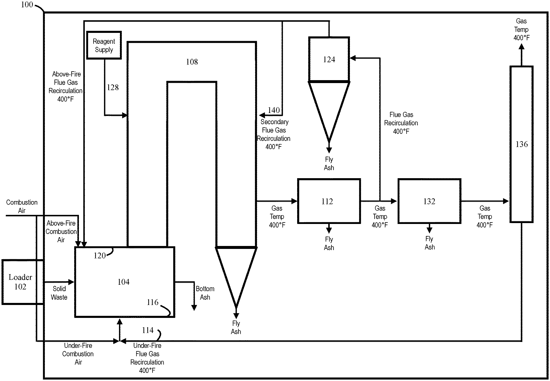
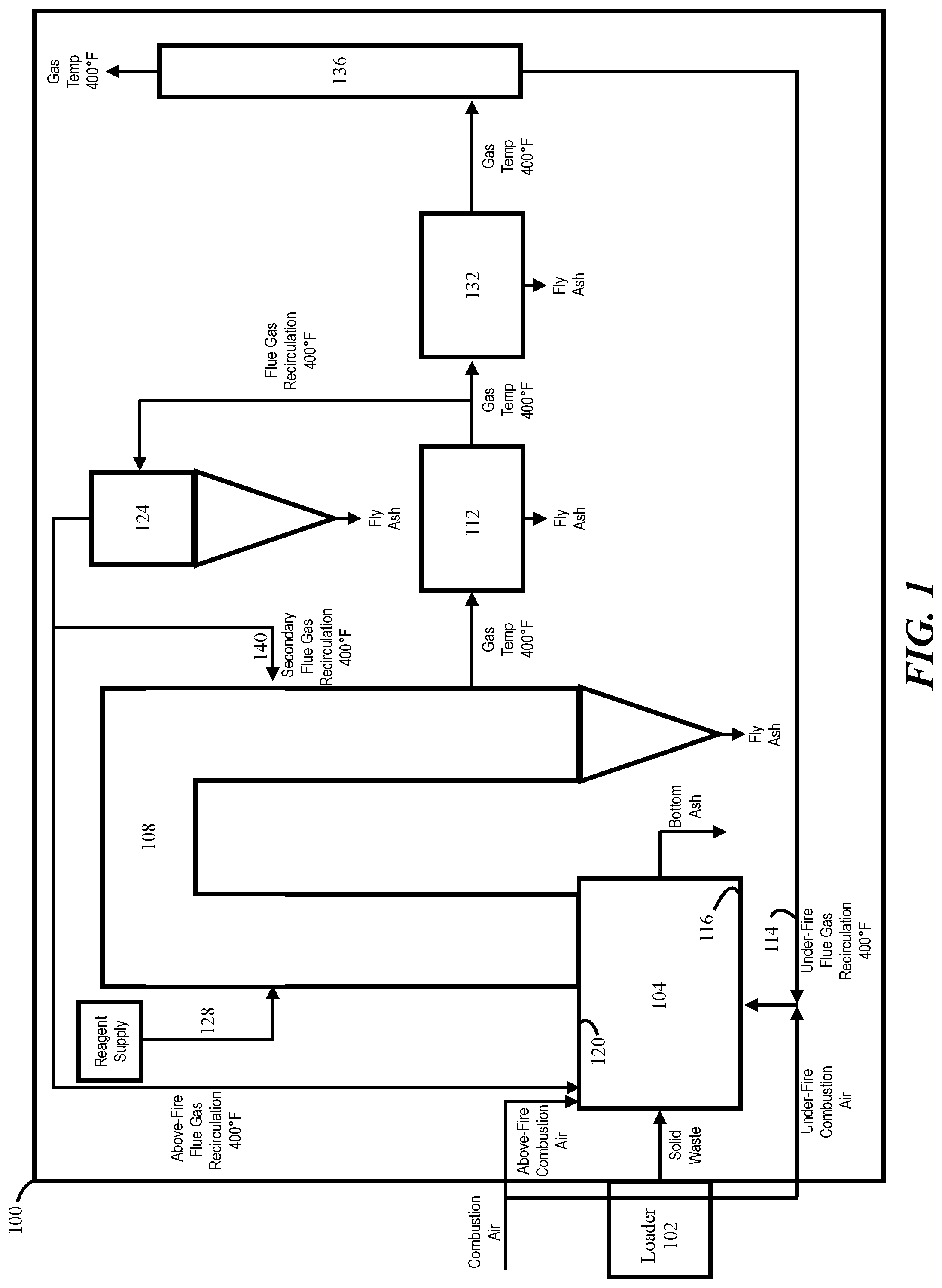
[0023] FIG. 1 illustrates an incinerator 100 having a primary combustion chamber 104 wherein waste materials are disposed and combusted to produce a flue gas. A loader 102 loads waste materials into the primary combustion chamber 104. The flue gas is oxidized in the primary combustion chamber 104 before being transferred to the secondary combustion chamber 108 along with the combusted waste materials. Each combustion chamber 104, 108 can be constructed as any one of several types of chambers, such as rotary kiln and moving or fixed hearth. The oxidized flue gas and combusted waste materials are transferred to a heat recovery system 112. Following the heat recovery system 112, a portion of the flue gas is recirculated to the primary combustion chamber 104 and secondary combustion chamber 108. Flue gas transferred to the primary combustion chamber 104 can be recirculated in two ways. The first includes a first portion 114 of the clean flue gas after scrubbing system 132 mixing with fresh under-fire air. The mixture of flue gas and the under-fire air is then injected into the hearth portion 116 primary combustion chamber 104 via apertures. The second includes a second portion of the flue gas mixing with above-fire air and injected into apertures positioned on the top portion 120 of the primary combustion chamber 104. The amount of flue gas partitioned into each of the first and second portions recirculated to the primary combustion chamber 104 is controlled depending on various temperatures and oxygen levels within the incinerator 100.
[0024] Gases and fly ash emitted from the partially combusted waste material as well as residual oxygen from the primary combustion chamber 104 enter into a secondary combustion chamber 108 where additional combustion occurs until the waste material is substantially combusted. Oxygen content is often controlled at less than 6%. An array of nozzles in the wall of the primary combustion chamber 104 injects cooled, recycled flue gases into the primary combustion chamber 104. These recycled gases enter the primary combustion chamber 104 immediately above the flames. The cooled, recycled flue gases maintain the temperature in the primary combustion chamber 104 at a predetermined temperature, generally about 1500 to 1832.degree. F. Similarly, the gases rising from the primary combustion chamber 104 into the second combustion chamber 108 are at temperatures between about 1500 to 1832.degree. F.
[0025] In some embodiments, the gas temperatures in the primary combustion chamber 104 ranges from 1500-1832.degree. F. A set temperature within the primary combustion chamber 104, such as, for example, 1812.degree. F. is controlled by gas dampers via a PLC 270 (shown in FIG. 2). Flue gas can be provided from the combustion air mixed with recirculated flue gas injected from the top portion 120 and hearth portion 116 of the primary combustion chamber 104. PLC 270 provides a dynamic means of controlling the combustion air fan along with a plurality of oxygen content sensors in communication with the gas dampers. Under-fire air is mixed with the first portion of recirculated flue gas and injected into the hearth portion 116 of the primary chamber 104. In some embodiments, the mix is injected underneath a waste pile within the primary combustion chamber 104. The under-fire and above-fire air maintain continuous combustion of waste materials within the primary combustion chamber 104 while keeping the waste material chamber at a near-constant temperature. Waste material may be maintained at a temperature of 1400.degree. F. to prevent metal or glass waste materials from melting which can result in blocked nozzles, and damage to the refractory layer of the primary combustion chamber 104.
[0026] Transfer of gasses is facilitated by conduit connecting the primary combustion chamber 104, secondary combustion chamber 108, heat recovery system 112, cyclone 124, air pollution control system 132, and stack 136.
[0027] Injection nozzles 120 are provided on various surfaces of the primary combustion chamber 104. Each injection nozzle 120 can be configured to pivot, rotate, or otherwise articulate to change the angle of injection of fresh, above-fire, and air.
[0028] In some embodiments, combustion air may be preheated by an air plenum of the primary combustion chamber 104. The second portion of flue gas recirculated via a recirculation blower downstream of the heat recovery system 112 which has a gas temperature of about 400.degree. F. The under-fire flue gas is recirculated via a second recirculation blower downstream of the air pollution control system 132 and has a temperature of about 400.degree. F.
[0029] In some embodiments, a cyclone 124 is utilized as a filter to precipitate fly ash from the remaining constituents of the flue gas. One skilled in the arts will understand that any suitable filter or gas-solids separator including, for example, a cyclone or a precipitator. The cyclone 124 may be any cyclone separator commercially available used to separate particulates from gases. A single cyclone 124 or multiple cyclones can be used. The cyclone 124 can be a multiple-tube cyclone which cleans hot gas to rid the gas of particles.
[0030] The size, shape, and dimension of the primary combustion chamber 104 and secondary combustion chamber 108 can be optimized by computational fluid dynamics (CFD) to optimize mixing and turbulence. Using CFD allows for the simulation of the gas flow routine to determine an optimal mixing method, injection angles of a plurality of nozzles (not shown), and positions of the inlets of combustion air mixed with recirculated flue gas.
[0031] In some embodiments, an SNCR process is utilized in the secondary combustion chamber 108 which is supplied with post-combustion flue gas from the primary combustion chamber 104 and the heat recovery system 112. The SNCR process utilized in the secondary combustion chamber 108 is a post-combustion NOx reduction process which reduces NOx via the controlled injection of a reagent, via a reagent supply line 128 (such as diluted urea) into the post-combustion flue gas path. The amount, distribution, and the injection position, and the injection angle of the reagent for the SNCR process is optimized by CFD simulations to achieve maximum NOx reduction efficiency, minimum ammonia slip, and minimum reagent consumption.
[0032] In some embodiments, the reagent can include a urea solution or an ammonia solution. The ammonia solution may be used in the SNCR method in the secondary combustion chamber 108.
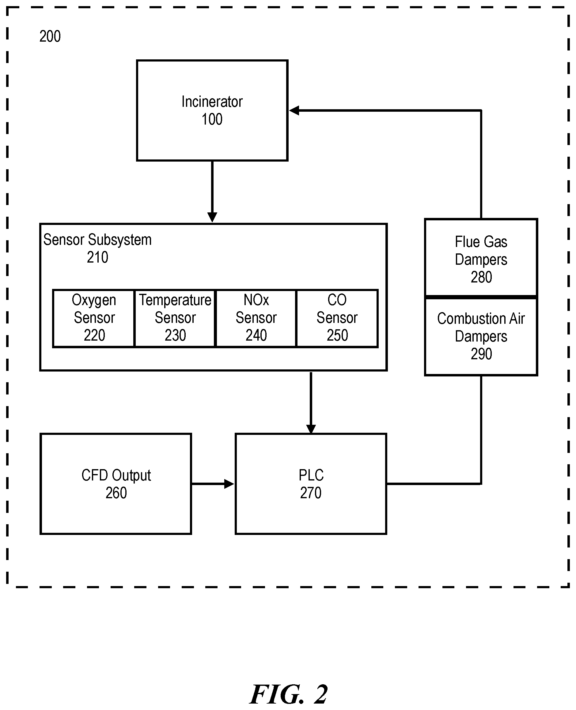
[0033] FIG. 2 illustrates a block diagram of the control system 200 in an exemplary embodiment. To improve incinerator efficiency while reducing NOx emissions, various incinerator parameters are measured to alter the components of the incinerator 100 dynamically. As discussed herein, the incinerator 100 includes a sensor subsystem 210 which can include but is not limited to oxygen sensors 220, temperature sensors 230, NOx sensors 240, and carbon monoxide (CO) sensors 250 each positioned throughout various components of the incinerator 100. Each sensor provides an output signal to a programmable logic controller (PLC) 270. The PLC 270 receives input from the sensor 210 to affect various components of the incinerator 100.
[0034] In some embodiments, the PLC 270 dynamically controls the amount of flue gas transferred to each of the primary and secondary combustion chambers 104, 108 based on the desired temperature and oxygen levels. The PLC 270 may also control the angle of the injection nozzles 120.
[0035] Oxygen sensors 220 measure oxygen levels and transmits output signals thereof to the PLC 270. An output signal is sent from the PLC 270 to control the opening and closing of combustion air dampers 290 which supply fresh air at a rate determined by the PLC 270 to maintain a given oxygen level within the incinerator 100. The PLC 270 affects the combustion air dampers 290 and flue gas dampers 280 independently to ensure the stability of various temperatures in the incinerator 100. Temperature stability provides complete combustion of the waste materials while minimizing the generation of thermal NOx. The formation of CO is restrained to acceptable levels which are predetermined by laws and regulations.
[0036] In some embodiments, ambient air having an oxygen content of about 21% is used as the combustion air for the overall reduction of NOx emissions. The oxygen content (21%) of ambient air is advantageous in providing high gas temperatures which results in complete combustion of waste materials and vitrification of bottom ash.
[0037] A temperature sensor 230, for example, a thermocouple, is used to measure the temperature inside the primary combustion chamber 104, the secondary combustion chamber 108, while the PLC 270 compares the measured primary combustion chamber 104 and secondary combustion chamber 108 temperatures, with one or more temperature set points. The PLC 270 then opens or closes flue gas dampers 280 accordingly, returning the required amount of recycled flue gases to the primary combustion chamber 104 and/or secondary combustion chamber 108. The recycling of cooled flue gases ensures better control of temperature in the primary combustion chamber 104 than when recycling is absent. It also increases the degree of combustion of the flue gases.
[0038] In some embodiments, NOx sensors 240 and CO sensors 250 are positioned on various components of the incinerator, most notably the stack 136 to measure emissions of NOx out of the incinerator 100 to ensure proper emission levels.
[0039] An SNCR method is provided to the secondary combustion chamber 108 to reduce NOx post-combustion in the primary chamber by up to 85%. A reagent (such as a urea solution) is dynamically injected into the secondary combustion chamber 108, via injection nozzles 128. The reagent amount, distribution of injection across the injection nozzles 128, and angle of the injection nozzles is controlled and optimized by the PLC 270. The CFD 260 is used to aid in determining various incinerator parameters which include the maximum NOx destruction efficiency, minimum ammonia slip, and minimum reagent consumption.
[0040] In some embodiments, temperature measurements and oxygen content control via flue gas recirculation are provided in the primary combustion chamber 104 wherein flue gas combustion and combustion air injection take place. Flue gas recirculation and combustion air injection may not be present in the secondary combustion chamber 108.
[0041] One skilled in the arts will understand that additional sensors including timers, pressure sensors, and infrared sensors can be in operable communication to provide further output signals to the PLC 270.
[0042] In some embodiments, the following incinerator parameters may be set points for the PLC 270. The reduction of NOx via SNCR is between 60-85%. Temperatures in the primary combustion chamber 104 may range between 1562-1832.degree. F. The secondary chamber 108 may have temperatures between 1562-1832.degree. F. A CO limit may be set, via the PLC 270, at the secondary combustion chamber inlet at 200 ppm while a CO limit at the secondary combustion chamber 108 may be set at 10 ppm. In one example, oxygen content may be set, via the PLC 270, at the secondary combustion chamber inlet at 6%. Post-Injection residence time may be set to two seconds.
[0043] In one aspect, a method for controlling NOx and CO emissions of an incinerator is provided. A plurality of emissions outputs (including NOx emissions and CO emissions) are modeled via a computation fluid dynamics module. An efficient model is determined which reduces NOx and CO emissions. The efficient module is determined by analyzing the emissions outputs for each model generated. The model having the lowest NOx and CO emissions while maintaining incinerator efficiency is selected. A signal output corresponding to the efficient model is transmitted to the programmable logic controller. Incinerator parameters are measured via a plurality of sensors and compared with the efficient model defined by a plurality of set points. The programmable logic controller then controls an amount of above-fire and under-fire combustion air, and an amount of above-fire and under-fire flue gas recirculation to reduce emissions of NOx and CO from the incinerator.
[0044] Many different embodiments have been disclosed herein, in connection with the above description and the drawings. It will be understood that it would be unduly repetitious and obfuscating to literally describe and illustrate every combination and subcombination of these embodiments. Accordingly, all embodiments can be combined in any way and/or combination, and the present specification, including the drawings, shall be construed to constitute a complete written description of all combinations and subcombinations of the embodiments described herein, and of the manner and process of making and using them, and shall support claims to any such combination or subcombination.
[0045] An equivalent substitution of two or more elements can be made for any one of the elements in the claims below or that a single element can be substituted for two or more elements in a claim. Although elements can be described above as acting in certain combinations and even initially claimed as such, it is to be expressly understood that one or more elements from a claimed combination can in some cases be excised from the combination and that the claimed combination can be directed to a subcombination or variation of a subcombination.
[0046] It will be appreciated by persons skilled in the art that the present embodiment is not limited to what has been particularly shown and described hereinabove. A variety of modifications and variations are possible in light of the above teachings without departing from the following claims.
* * * * *
D00000
D00001
D00002
XML
uspto.report is an independent third-party trademark research tool that is not affiliated, endorsed, or sponsored by the United States Patent and Trademark Office (USPTO) or any other governmental organization. The information provided by uspto.report is based on publicly available data at the time of writing and is intended for informational purposes only.
While we strive to provide accurate and up-to-date information, we do not guarantee the accuracy, completeness, reliability, or suitability of the information displayed on this site. The use of this site is at your own risk. Any reliance you place on such information is therefore strictly at your own risk.
All official trademark data, including owner information, should be verified by visiting the official USPTO website at www.uspto.gov. This site is not intended to replace professional legal advice and should not be used as a substitute for consulting with a legal professional who is knowledgeable about trademark law.