Groundwater Sampling Pump
A1
U.S. patent application number 16/862123 was filed with the patent office on 2020-08-13 for groundwater sampling pump. The applicant listed for this patent is Q.E.D. Environmental Systems, Inc.. Invention is credited to Douglas D. COLBY, Thomas T. REESBECK.
| Application Number | 20200256342 16/862123 |
| Document ID | 20200256342 / US20200256342 |
| Family ID | 1000004786744 |
| Filed Date | 2020-08-13 |
| Patent Application | download [pdf] |


View All Diagrams
| United States Patent Application | 20200256342 |
| Kind Code | A1 |
| COLBY; Douglas D. ; et al. | August 13, 2020 |
GROUNDWATER SAMPLING PUMP
Abstract
The present disclosure relates to a sampling pump configured for use in a wellbore for pumping liquid collecting in the wellbore. The sampling pump has a pump component including a motor and an outer housing configured to be inserted into the well bore. The outer housing has an inlet and an outlet. A fluid sensor detects when the inlet of the outer housing is positioned in the liquid in the wellbore. A flexible electrical cable assembly supplies power to the motor and the fluid sensor, and also communicates with the motor and the fluid sensor. A user control panel communicates with the flexible electrical cable and enables a user to control on and off operation of the DC motor from the control panel. The user control panel also has a component which is responsive to signals from the fluid sensor to indicate when the inlet is at least partially submerged in the liquid within the wellbore, as the pump is lowered into the wellbore.
| Inventors: | COLBY; Douglas D.; (Clarkston, MI) ; REESBECK; Thomas T.; (Ann Arbor, MI) | ||||||||||
| Applicant: |
|
||||||||||
|---|---|---|---|---|---|---|---|---|---|---|---|
| Family ID: | 1000004786744 | ||||||||||
| Appl. No.: | 16/862123 | ||||||||||
| Filed: | April 29, 2020 |
Related U.S. Patent Documents
| Application Number | Filing Date | Patent Number | ||
|---|---|---|---|---|
| 15100904 | Jun 1, 2016 | |||
| PCT/US2014/068371 | Dec 3, 2014 | |||
| 16862123 | ||||
| 61911273 | Dec 3, 2013 | |||
| Current U.S. Class: | 1/1 |
| Current CPC Class: | F04D 13/068 20130101; F04D 13/10 20130101; F04D 5/008 20130101; F04D 15/0218 20130101; F04D 5/002 20130101; F04D 13/0693 20130101; F04D 13/086 20130101; E21B 49/084 20130101 |
| International Class: | F04D 13/08 20060101 F04D013/08; F04D 13/10 20060101 F04D013/10; F04D 15/02 20060101 F04D015/02; F04D 13/06 20060101 F04D013/06; E21B 49/08 20060101 E21B049/08; F04D 5/00 20060101 F04D005/00 |
Claims
1. A sampling pump configured for use in a wellbore for pumping liquid collecting in the wellbore, the sampling pump comprising: a pump component including: a motor; an outer housing configured to be inserted into the well bore; the outer housing having an inlet and an outlet; a fluid sensor configured to detect when the inlet of the outer housing is positioned in the liquid in the wellbore; a flexible electrical cable assembly for supplying power to the motor and the fluid sensor, and also for communicating with the motor and the fluid sensor; a user control panel in communication with the flexible electrical cable and configured to enable a user to control on and off operation of the DC motor from the control panel; and the user control panel further including a component responsive to signals from the fluid sensor to indicate when the inlet is at least partially submerged in the liquid within the wellbore, as the pump is lowered into the wellbore.
2. The sampling pump of claim 1, wherein the component provides: a first indication when the inlet of the outer housing the pump component is positioned in air; and a second indication when the inlet of the outer housing of the pump component is submerged in the liquid in the wellbore.
3. The sampling pump of claim 1, wherein the first and second indications comprise visual indications.
4. The sampling pump of claim 1, wherein at least one of the first and second visual indications comprises a blinking visual indication, and the other one of the first and second visual indications comprises a continuous visual indication.
5. The sampling pump of claim 3, wherein the component comprises an optical component, and wherein the optical component is configured to flash intermittently before contacting fluid, and then to remain in a continuously illuminated state while the inlet of the outer housing of the pump component is submerged in the liquid.
6. The sampling pump of claim 4, wherein the component comprises an LED.
7. The sampling pump of claim 1, further comprising a frame for supporting the electrical cable assembly.
8. The sampling pump of claim 7, further comprising a reel mounted for rotation on the frame, the reel enabling the electrical cable assembly to be unwound therefrom as the pump component is lowered down into the wellbore, and wound thereon as the pump component is withdrawn from the wellbore.
9. The sampling pump of claim 1, wherein the control panel further includes a connector for connecting an external DC power source to the control panel to power the pump component and the fluid sensor.
10. The sampling pump of claim 1, wherein the flexible electrical cable assembly includes markings thereon to indicate a length unit of measurement.
11. The sampling pump of claim 1, wherein the motor comprises a brushless DC motor.
12. The sampling pump of claim 1, further comprising: a DC battery carried on the frame and electrically coupled to the fluid sensor for powering the fluid sensor; and a first switch associated with the control panel for turning on and off DC power to the fluid sensor.
13. The sampling pump of claim 1, further comprising a second switch on the control panel for enabling a user to power on and off the motor.
14. The sampling pump of claim 1, wherein the indicator comprises an optical device that provides an optical signal to indicate to a user when the fluid sensor has been submerged in fluid.
15. The sampling pump of claim 14, wherein the optical device flashes intermittently before contacting fluid, and then remains in a continuously illuminated state while submerged in fluid.
16. A sampling pump configured for use in a wellbore for pumping liquid collecting in the wellbore, the sampling pump comprising: a frame; a pump component including: a motor; an outer housing configured to be inserted into the well bore; the outer housing having an inlet and an outlet; a fluid sensor configured to detect when the outer housing is positioned in fluid in the wellbore; a flexible electrical cable assembly coupled at one end to the pump component for supplying power to the motor and the fluid sensor of the pump component, and also for communicating with the motor and the fluid sensor, the flexible electrical cable and the pump component; a reel supported from the frame for rotational movement; the reel operable to support the flexible electrical cable assembly thereon; a user control panel in communication with the flexible electrical cable and configured to enable a user to control on and off operation of the DC motor from the user control panel; and the user control panel further including: a component responsive to signals from the fluid sensor to indicate when the pump is at least partially submerged in the liquid within the wellbore, as the pump is lowered into the wellbore; and a speed control component for controlling a speed of the motor, and thus a liquid flow rate produced by the pump component.
17. The sampling pump of claim 16, wherein the user control panel is centrally mounted on the reel.
18. The sampling pump of claim 16, wherein the frame includes a structure for receiving the pump component and storing the pump component when the pump component is not in use.
19. A sampling pump configured for use in a wellbore for pumping liquid collecting in the wellbore, the sampling pump comprising: a frame; a pump component including: a motor; an outer housing configured to be inserted into the well bore; the outer housing having an inlet and an outlet; a fluid sensor configured to detect when the outer housing is positioned in fluid in the wellbore; a flexible electrical cable assembly coupled at one end to the pump component for supplying power to the motor and the fluid sensor of the pump component, and also for communicating with the motor and the fluid sensor, the flexible electrical cable and the pump component; a reel supported from the frame for rotational movement; the reel operable to support the flexible electrical cable assembly thereon; a user control panel in communication with the flexible electrical cable and configured to enable a user to control on and off operation of the DC motor from the user control panel, the user control panel being centrally located within the reel; and the user control panel further including: a component responsive to signals from the fluid sensor to provide a first visual indication when the lower end of the housing of the pump component is located in air within the wellbore, and a second visual indication when the lower end of the housing becomes at least partially submerged in the liquid within the wellbore during lowering of the pump component into the wellbore; a speed control component for controlling a speed of the motor, and thus a liquid flow rate produced by the pump component; and the user control panel controlling the motor during operation of the sampling pump so that the motor is automatically turned off when the fluid sensor detects that it is no longer submerged in fluid.
20. The sampling pump of claim 19, wherein: the control panel includes a microcontroller for controlling operation of the motor; the control panel is configured to log a total run time that the pump component is running and to display the total run time to a user; and the control panel includes a short range wireless transceiver for enabling the control panel to communicate wirelessly with a remote personal electronic device of a user.
Description
CROSS-REFERENCE
[0001] The present application is a continuation and claims priority to U.S. application Ser. No. 15/100,904, filed Jun. 1, 2016; which is a U.S. national phase of PCT/US2014/068371, filed Dec. 3, 2014 and published in English as WO2015/084957 on Jun. 11, 2015; which claims priority to U.S. Provisional Patent Application No. 61/911,273, filed Dec. 3, 2013. The entire disclosure of each of the above applications are incorporated herein by reference.
FIELD
[0002] The present disclosure relates to groundwater sampling pumps and pump control systems therefor, used to collect water samples from groundwater fed wells.
BACKGROUND
[0003] This section provides background information related to the present disclosure which is not necessarily prior art.
[0004] Groundwater sample pump systems are known which use DC motors to pump effluent from a well upward to ground level where a sample is drawn for off-site analysis. Known systems use a full speed pump and a throttle device at a discharge location to reduce discharge flow for collecting the sample. A disadvantage of known systems is that the throttle device reduces volume flow rate, but locally increases the flow velocity, making collection of a small volume sample difficult. In addition, power consumption of known groundwater sample pump systems can range from 20 up to 40 Amperes, and commonly requires a high current AC power source with an AC/DC converter to provide DC power for pump motor operation, which is both heavy and expensive. An AC power source is often not available at remote well sites, therefore the operator must bring a separate source of AC power. Also, known sampling systems use a centrifugal pump which at operating speed (12,000 to 15,000 rpm) results in cavitation at the impeller when the flow rate is reduced downstream by the sample throttle device.
SUMMARY
[0005] This section provides a general summary of the disclosure, and is not a comprehensive disclosure of its full scope or all of its features.
[0006] In one aspect the present disclosure relates to a sampling pump configured for use in a wellbore for pumping liquid collecting in the wellbore. The sampling pump may comprise a pump component including a motor and an outer housing configured to be inserted into the well bore. The outer housing has an inlet and an outlet. A fluid sensor is also configured to detect when the inlet of the outer housing is positioned in the liquid in the wellbore. A flexible electrical cable assembly is included for supplying power to the motor and the fluid sensor, and also for communicating with the motor and the fluid sensor. A user control panel is included which is in communication with the flexible electrical cable and configured to enable a user to control on and off operation of the DC motor from the control panel. The user control panel further includes a component responsive to signals from the fluid sensor to indicate when the inlet is at least partially submerged in the liquid within the wellbore, as the pump is lowered into the wellbore.
[0007] In another aspect the present disclosure relates to a sampling pump configured for use in a wellbore for pumping liquid collecting in the wellbore. The sampling pump may comprise a frame and a pump component. The pump component may include a motor and an outer housing configured to be inserted into the well bore. The outer housing may have an inlet and an outlet. A fluid sensor may be included on the pump component which is configured to detect when the outer housing is positioned in fluid in the wellbore. A flexible electrical cable assembly is coupled at one end to the pump component for supplying power to the motor and the fluid sensor of the pump component, and also for communicating with the motor and the fluid sensor, the flexible electrical cable and the pump component. A reel is supported from the frame for rotational movement and is operable to support the flexible electrical cable assembly thereon. A user control panel is included which is in communication with the flexible electrical cable and configured to enable a user to control on and off operation of the DC motor from the user control panel. The user control panel further may include a component responsive to signals from the fluid sensor to indicate when the pump is at least partially submerged in the liquid within the wellbore, as the pump is lowered into the wellbore. The control panel may also include a speed control component for controlling a speed of the motor, and thus a liquid flow rate produced by the pump component.
[0008] In still another aspect the present disclosure relates to a sampling pump configured for use in a wellbore for pumping liquid collecting in the wellbore. The sampling pump may comprise a frame and a pump component. The pump component may include a motor and an outer housing configured to be inserted into the well bore. The outer housing may have an inlet and an outlet. A fluid sensor may be included which is configured to detect when the outer housing is positioned in fluid in the wellbore. A flexible electrical cable assembly may also be included which is coupled at one end to the pump component for supplying power to the motor and the fluid sensor of the pump component, and also for communicating with the motor and the fluid sensor, the flexible electrical cable and the pump component. A reel is supported from the frame for rotational movement and is operable to support the flexible electrical cable assembly thereon. A user control panel may be included which is in communication with the flexible electrical cable and configured to enable a user to control on and off operation of the DC motor from the user control panel. The user control panel may be centrally located within the reel and may include a component responsive to signals from the fluid sensor to provide a first visual indication when the lower end of the housing of the pump component is located in air within the wellbore, and a second visual indication when the lower end of the housing becomes at least partially submerged in the liquid within the wellbore during lowering of the pump component into the wellbore. The control panel may further include a speed control component for controlling a speed of the motor, and thus a liquid flow rate produced by the pump component. The user control panel controls the motor during operation of the sampling pump so that the motor is automatically turned off when the fluid sensor detects that it is no longer submerged in fluid.
[0009] In another aspect the present disclosure relates to a sampling pump assembly including a pump outer housing having an inlet end cap with multiple water inlet ports. The inlet end cap is connected to the pump outer housing using bayonet pins extending through L-shaped slots in a first housing connector. An outlet end cap is connected to the pump outer housing using bayonet pins and has a tubing connector for releasably connecting an effluent tube thereto. A pump is included which has a regenerative impeller connected to a brushless DC motor. The brushless DC motor is positioned within the pump outer housing and the regenerative impeller is positioned within the inlet end cap. The brushless DC motor may operate at approximately 8,000 rpm providing a lift of at least up to about 150 feet, and possibly higher. A sensor extends beyond the outlet end cap and provides a sensing signal when the pump assembly becomes submerged below a water surface in a wellbore in which the pump outer housing is positioned. A reel assembly is included which has a rotatable support reel for supporting a flexible cable assembly for supplying DC power to the brushless DC motor. The flexible cable assembly is able to be wound onto the rotatable support reel. At least one internal battery is carried by the reel assembly which provides electrical power for the sensor. An LED is provided with the reel assembly and is configured to flash continuously as the sampling pump assembly is lowered into a wellbore and prior to the sensor contacting water. The LED changes to a continuously illuminated condition when the pump assembly extends below a water level surface in the wellbore. Multiple distance marks are created on the flexible cable assembly to enable a user to determine a depth that the pump outer housing is positioned within the wellbore.
[0010] According to several additional aspects, a sampling pump assembly includes a pump outer housing having a housing inlet end releasably connected thereto. The housing inlet end includes multiple water inlet ports and is connected to the pump outer housing using one or more bayonet pins radially extending through one or more L-shaped slots created in a first housing connector. At an opposite end of the pump outer housing from the housing inlet end is an inlet end cap which is similarly connected using one or more bayonet pins received in an L-shaped slot of a second housing connector. The inlet end cap receives a tubing connector for releasably connecting an effluent tube. A sensor extends beyond the inlet end cap and provides a sensing function for the period when sampling pump assembly is operated and submerged below a water volume surface.
[0011] In various other aspects of the present disclosure the sampling pump assembly is readied to be lowered into a well, a first switch, located on a control panel of the reel, is switched from an "off" to an "on" position. An internal battery provided within the reel provides sufficient electrical power for operation of the sensor as the sampling pump assembly is lowered. An LED also present on the control panel flashes continuously as the sampling pump assembly is lowered into the well and prior to sensor contacting a water volume within the well. As the sampling pump assembly enters the water volume and extends below a water level surface, water contacts the sensor, which creates an electrical signal indicating that the entire sampling pump assembly is positioned below the water level surface. At this time, the LED changes from a continuous flashing condition to a continuous energized "on" condition. The "on" condition of the LED visually indicates to the operator that the sampling pump assembly is fully submerged within the water volume.
[0012] After the LED changes to the continuous "on" condition, the sampling pump assembly is drawn upward until the LED changes back to the continuous flashing operation, at which time a plurality of distance marks provide a depth indicated in 1 foot incremental positions along the outer casing of a cable assembly identifying depth in feet of the position of the sampling pump assembly within the well. The sampling pump assembly is lowered back into the well until the LED changes again to the continuous "on" condition. An external source of 12 VDC electrical power is then connected to the reel and the operator switches a second switch from an "off" to an "on" position, which starts operation of the DC motor.
[0013] Further areas of applicability will become apparent from the description provided herein. The description and specific examples in this summary are intended for purposes of illustration only and are not intended to limit the scope of the present disclosure.
DRAWINGS
[0014] The drawings described herein are for illustrative purposes only of selected embodiments and not all possible implementations, and are not intended to limit the scope of the present disclosure.
[0015] FIG. 1 is a front elevational view of a groundwater sampling pump of the present disclosure;
[0016] FIG. 2 is an end elevational view of the pump of FIG. 1;
[0017] FIG. 3 is a cross sectional side elevational view taken at section 3 of FIG. 1;
[0018] FIG. 4 a front elevational view of an impeller housing assembly of the present disclosure;
[0019] FIG. 5 is a cross sectional front elevational view taken at section 5 of FIG. 4;
[0020] FIG. 6 is a top plan view of the impeller housing of FIG. 4;
[0021] FIG. 7 is a bottom plan view of an impeller retention member of the housing assembly of FIG. 4;
[0022] FIG. 8 a front perspective view of a groundwater sampling pump and reel assembly of the present disclosure including the groundwater sampling pump of FIG. 1;
[0023] FIG. 9 is a partial cross sectional front elevational view of the groundwater sampling system mounted to a well pipe;
[0024] FIG. 10 is a front elevational view of a control panel provided on a reel of the groundwater sampling system;
[0025] FIG. 11 is a graph of flow rate versus well depth for the groundwater sampling system of the present disclosure;
[0026] FIG. 12 is a circuit diagram of a control system for the groundwater sampling pump of FIG. 8;
[0027] FIG. 13 is a circuit diagram of a pump control system portion for the groundwater sampling pump of FIG. 8;
[0028] FIG. 14 is a side elevation view of another embodiment of a groundwater sampling pump in accordance with the present disclosure;
[0029] FIG. 15 is a view of a portion of the pump assembly of FIG. 14;
[0030] FIG. 15a is an enlarged view of the circled portion in FIG. 15;
[0031] FIG. 16 is a cross sectional side view of the bayonet pins engaged within their respective slots and compressing a gasket to achieve a watertight seal within the pump housing;
[0032] FIG. 17 is a cross sectional side view of an annular, replaceable motor shaft seal that is used in the pump assembly of FIG. 14;
[0033] FIG. 18 is a plan view of a first surface of an impeller retainer used in the pump assembly of FIG. 14;
[0034] FIG. 19 is a side view of the impeller retainer of FIG. 18;
[0035] FIG. 20 is a plan view of a second surface (i.e., opposing surface) of the impeller retainer of FIG. 18;
[0036] FIG. 21 is a plan view of a first surface of an impeller housing used in the pump assembly of FIG. 14;
[0037] FIG. 22 is a side view of the impeller housing shown in FIG. 21; and
[0038] FIG. 23 is a plan view of a second surface (i.e., opposing surface) of the impeller housing of FIG. 21.
[0039] Corresponding reference numerals indicate corresponding parts throughout the several views of the drawings.
DETAILED DESCRIPTION
[0040] Example embodiments will now be described more fully with reference to the accompanying drawings.
[0041] Referring to FIG. 1, a sampling pump assembly 10 includes a pump outer housing 12 having a housing inlet end 14 releasably connected thereto. The housing inlet end 14 includes multiple water inlet ports 16. The housing inlet end 14 is connected to the pump outer housing 12 using one or more bayonet pins 18 radially extending through an L-shaped slot 20 created in a first housing connector 22. The housing inlet end 14 is oriented such that the bayonet pin 18 is received in the L-shaped slot, and the housing inlet end 14 is axially rotated to releasably lock the housing inlet end 14 in position. At an opposite end of the pump outer housing 12 from the housing inlet end 14 is an outlet end cap 24 which is similarly connected using one or more bayonet pins 26 received in an L-shaped slot 28 of a second housing connector 30. The outlet end cap 24 receives a tubing connector 32 for releasably connecting an effluent tube shown and described in greater detail in reference to FIG. 9. A sensor 34 extends beyond the outlet end cap 24 and provides a sensing function for the period when sampling pump assembly 10 is operated and submerged below a water volume surface, as described in greater detail in reference to FIG. 9. According to several aspects, the sampling pump assembly components such as the pump outer housing 12, the housing inlet end 14, and the outlet end cap 24 can be constructed of a metal material, such as stainless steel. Other materials can also be used.
[0042] Referring to FIG. 2 and again to FIG. 1, the tubing connector 32 communicates with a discharge chamber 36 where water pumped by the sampling pump assembly 10 is received for discharge. A conduit connector 38 is also provided which provides the ability to both receive and seal conduits providing electric power as well as control signals to the operating components of sampling pump assembly 10.
[0043] Referring to FIG. 3 and again to FIGS. 1-2, a conduit 39 is shown in an exemplary position retained by the conduit connector 38. The conduit 39 provides electrical power, as previously noted, for operating the components of sampling pump assembly 10. The housing inlet end 14 provides an inlet chamber 40 proximate to a housing inlet end wall 14a. A filter 42, such as a metal or plastic screen, is releasably connected to an inlet end wall 44 which defines a boundary wall for the inlet chamber 40 opposite to the housing inlet end wall 14a. Water flowing into the inlet chamber 40, via the water inlet ports 16, passes through the filter 42 and enters an impeller chamber 46. The inlet end wall 44 defines a portion of housing inlet end 14 which is sealed against an inner perimeter wall of pump outer housing 12 at the time the bayonet pins 18 are engaged, using one or more seal members 48 such as O-rings. A pump element in the form of a "regenerative" impeller 50, positioned within impeller chamber 46, is held in rotational position using an impeller retainer 52. A connecting member 54 extends partially through and positively rotatably engages impeller 50. The connecting member 54 extends through a motor shaft seal 55 to allow for fluid sealed rotation of impeller 50. Impeller 50 is connected to and rotated by operation of a brushless DC motor 56 having a motor shaft 57 extending into and connected with the connecting member 54. The motor shaft seal 55 prevents water within impeller chamber 46 from entering a sealed enclosure having DC motor 56 contained therein. A circuit board 58, as well as DC motor 56, are positioned within a watertight cavity 60 provided by a pump inner housing 62 which is slidably received within the pump outer housing 12. The components of the circuit board 58 may be potted to hermetically seal them. Additionally, a plurality of electrically conductive metal pins 61 may project from the circuit board 58 into the space between the motor 56 and the edge of the circuit board 58 to detect if water is present in this space. The metal pins 61 sense the presence of water by detecting when a conductive path between them has been formed.
[0044] The brushless DC motor 56 using regenerative impeller 50 can operate at lower speed (approximately 8,000 rpm) than known pump systems. This provides the necessary lift while minimizing pump cavitation.
[0045] A flow passage 64 is circumferentially created between a tubular shaped outer perimeter wall of the pump inner housing 62 and an inner wall of the tubular shaped pump outer housing 12. Fluid discharged by operation of the impeller 50 passes through the flow passage 64 in a flow direction "A" to be subsequently discharged from the sampling pump assembly 10. As the impeller 50 is rotated by operation of DC motor 56, fluid drawn through the impeller 50 from the impeller chamber 46 is radially outwardly discharged into an impeller outlet region 66 which communicates with the flow passage 64.
[0046] After the water flows from the impeller outlet region 66 and through the flow passage 64, the water flow enters one or more collecting ports 68 and further flows through a discharge port 70 created in a pump top end member 72. The pump top end member 72 is received within the outlet end cap 24 and is provided with a plurality of end member seals 74, such as O-rings, to provide a fluid seal between pump top end member 72 and an inner wall of the pump inner housing 62. The end member seals 74 therefore prevent water within either the collecting ports 68 or discharge port 70 from entering the watertight cavity 60. After flowing through the discharge port 70, the pumped water enters the discharge chamber 36. The tubing connector 32 is releasably coupled to the pump top end member 72 using connector threads 76 such that a discharge bore 78 of the tubing connector 32 is coaxially aligned with discharge chamber 36. All of the water pumped by rotation of impeller 50 therefore discharges from discharge chamber 36 via discharge bore 78. Similar to the tubing connector 32, the conduit connector 38 is threadably connected to the pump top end member 72 using conduit connector threads 80. According to several aspects, there are two diametrically opposed ones of the bayonet pins 18 provided as bayonet pins 18, 18' and two diametrically opposed ones of the bayonet pins 26 provided as bayonet pins 26, 26'. The quantity of bayonet pins can vary at the discretion of the manufacturer.
[0047] Referring to FIG. 4 and again to FIG. 3, an impeller assembly 82 includes the impeller retainer 52 partially extending from an impeller housing 84. The impeller housing 84 can be fixed about its circumference to the pump outer housing 12, for example by welding.
[0048] Referring to FIG. 5 and again to FIG. 4, the impeller assembly 82 provides the impeller housing 84, which includes a housing flange 86 extending radially outward from the impeller housing 84 to provide a location for fixing the impeller housing 84 to the pump outer housing 12. A housing cylinder wall 88 is cylindrical in shape and includes both a first counterbore 90 and a second counterbore 92 created therein. The impeller 50 is rotatably positioned within the first counterbore 90, and the impeller retainer 52 is non-rotatably received in the second counterbore 92. The first counterbore 90 has a smaller diameter than a diameter of the second counterbore 92 such that the impeller retainer 52 overlaps the impeller 50. A clearance "B" is provided between an outer perimeter wall of the impeller 50 and the inner wall defined by the first counterbore 90. Clearance "B" allows for a water film to be continuously provided between the impeller 50 and the housing cylinder wall 88, thereby minimizing friction as the impeller 50 rotates. A connecting member slot 94 is centrally created through the impeller 50 which receives and engages the connecting member 54 extending from the motor shaft 57, thereby providing positive engagement for rotation of impeller 50. A seal ring slot 96 is provided proximate to the connecting member slot 94 to provide for a seal between the connecting member 54 and the impeller housing 84.
[0049] The impeller housing 84 is provided with a discharge opening 98 through which the water displaced by rotation of impeller 50 is received. The discharge opening 98 is in communication with a semicircular shaped discharge channel 100 which is created as a recess on a housing inner face 101 of impeller housing 84. The discharge channel 100 is in fluid communication with multiple impeller flow passages 102 extending through impeller 50. The housing inner face 101 is spaced from an impeller discharge side 104 of impeller 50 also by a fluid layer, minimizing friction as the impeller 50 rotates. On an opposite side of impeller 50 from the impeller discharge side 104 is an impeller supply side 106. A semicircular shaped supply channel 107 is created as a recess in a retainer face 108 of the impeller retainer 52. Multiple impeller vanes 109, positioned within the impeller flow passages 102, direct water which is provided through semicircular supply channel 107 into the semicircular discharge channel 100. The semicircular supply channel 107 is created in a retainer first portion 110 which as previously noted is received within the second counterbore 92 of housing cylinder wall 88. A threaded bore 112 is created in a retainer second portion 114 which can have a smaller diameter than the retainer first portion 110. The threaded bore 112 allows for a threaded tool (not shown) to be used to remove the impeller retainer 52 and thereby to remove the impeller 50 for service.
[0050] Referring to FIG. 6 and again to FIG. 5, the semicircular discharge channel 100 extends from a tapered minimum area channel end 116, in a semicircular path, to a maximum area channel end 118, positioned proximate to the discharge opening 98. All of the water entering semicircular discharge channel 100 is thereby discharged out through discharge opening 98.
[0051] Referring to FIG. 7 and again to FIG. 5, the semicircular supply channel 107, created in the retainer face 108 of impeller retainer 52, begins at a tapered minimum area channel end 120 and extends in a semicircular path to a maximum area channel end 122 positioned proximate to an inlet bore 124 extending axially through the retainer first portion 110 of impeller retainer 52. All water entering inlet bore 124 therefore passes through the semicircular supply channel 107 to be drawn through the impeller vanes 109 of impeller 50 and discharged into the semicircular discharge channel 100.
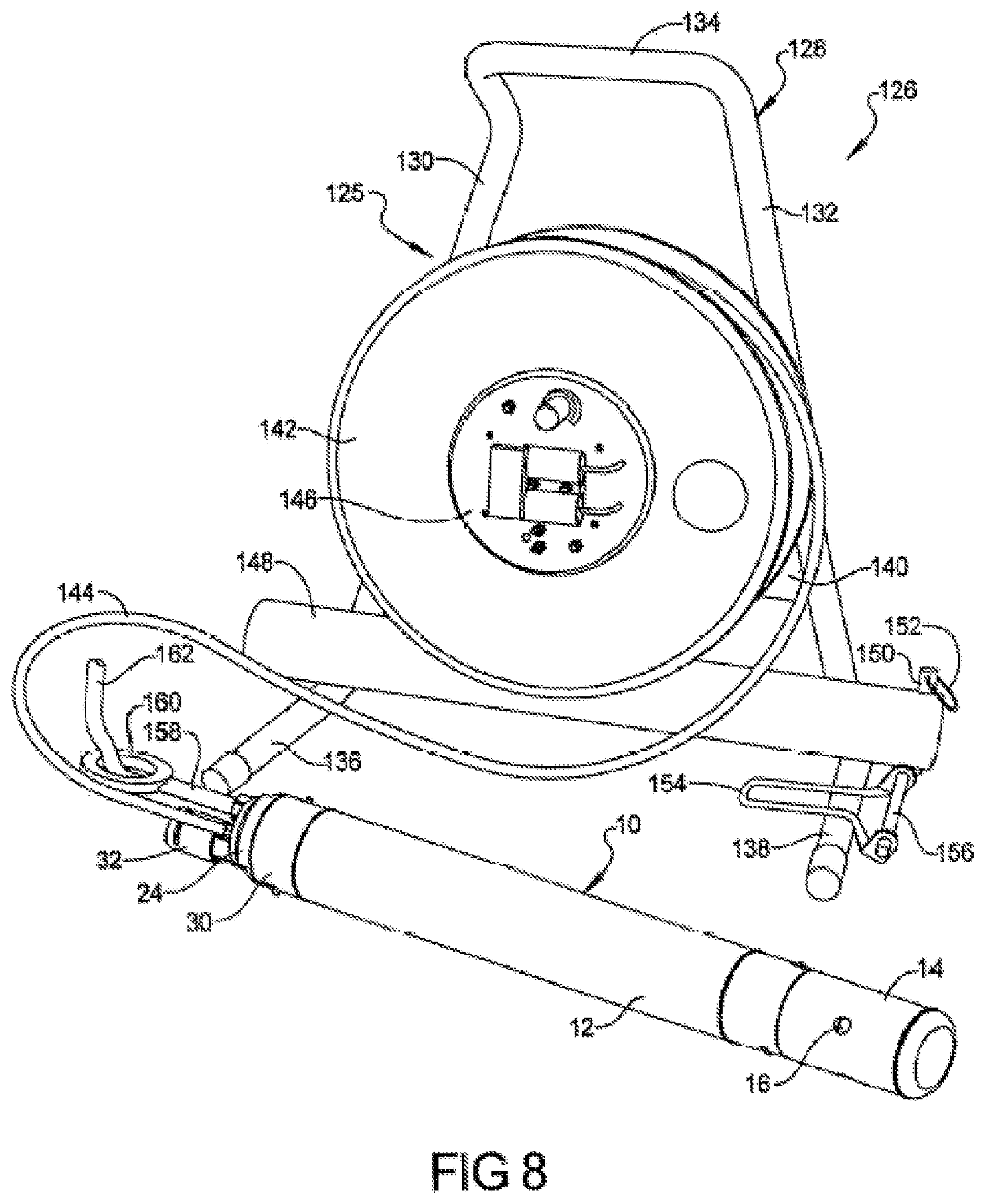
[0052] Referring to FIG. 8 and again to FIGS. 1-3, the sampling pump assembly 10 forms a portion of a groundwater sampling pump system 126. The groundwater sampling pump system 126 further includes a reel assembly 125 having an A-shaped frame 128 that can be made, for example, from metal tubing. The A-shaped frame 128 includes each of a first arm 130 and an oppositely positioned second arm 132 supported therebetween by a handle portion 134. The handle portion 134 is provided to allow manual carrying of the groundwater sample pump system 126. A first leg 136 extends at a substantially transverse orientation with respect to a distal end of first arm 130. A second leg 138 similarly extends from the second arm 132. The first and second legs 136, 138 allow the groundwater sampling pump system 126 to be either supported from a ground surface or from a well pipe which will be better described in reference to FIG. 9. A bracket 140 is fixed between each of the first and second arms 130, 132 and rotatably supports a reel 142 on the A-shaped frame 128. An electrical cable assembly 144 is wound onto reel 142 and is electrically connected to the sampling pump assembly 10. A control panel 146 supported at a central portion of the reel 142 provides local operator control and operation of groundwater sampling pump system 126, as will be better described in reference to FIGS. 9 and 10. A hollow tube 148 is fixed to each of the first and second arms 130, 132 proximate to a juncture with the first and second legs 136, 138. The hollow tube 148 also acts as a storage tube where the sampling pump assembly 10 can be internally stored when not in use. The sampling pump assembly 10 is retained within the storage or hollow tube 148 using a releasable pin 150 installed or withdrawn using a pin loop 152 connected to the releasable pin 150.
[0053] A U-shaped brace 154 is connected to a post 156 which is fixed to the storage or hollow tube 148. The U-shaped brace 154 assists with mounting the groundwater sampling pump system 126 to a well pipe, which is shown and better described in reference to FIG. 9. In addition to the cable assembly 144 connected to the sampling pump assembly 10, a rigid support rod 158, having an eyelet 160, can be releasably fixed to the pump top end member 72 of sampling pump assembly 10. A lift cable 162, such as a braided steel wire, can be connected to the eyelet 160 and extended into the well along with sampling pump assembly 10 if it is desired to use additional lift capability for removal of sampling pump assembly 10 from the well.
[0054] Referring to FIG. 9 and again to FIGS. 3 and 8, the groundwater sampling pump system 126 can be temporarily attached to a well 164 normally configured as a well pipe partially extending above a ground level 166 and predominantly extending below the ground level 166. The sampling pump assembly 10 is inserted downwardly into an interior bore 168 of the well 164 to draw water samples from the well 164 by unreeling the cable assembly from reel 142. The U-shaped brace 154 is positioned within the interior bore 168 of well 164 and makes direct contact with a well inner wall surface 170, while the second leg 138 is positioned in direct contact with a well upper surface 172, and the first leg 136 is positioned in direct contact with a well outer wall surface 174 of well 164. This configuration of groundwater sample pump system 126 positions the post 156 proximate to an opening of well 164. In addition to supporting the U-shaped brace 154, the post 156 provides a bearing surface for sliding motion of cable assembly 144 as the sampling pump assembly 10 is inserted and/or withdrawn into or out of the well 164. Prior to insertion of the sampling pump assembly 10, an effluent tube 176, such as a clear plastic tube, is connected to the tubing connector 32 of sampling pump assembly 10. During insertion of the sampling pump assembly 10, both the cable assembly 144 and the effluent tube 176 are lowered at approximately the same rate to prevent bends from forming in either of these items within the well. If the lift cable 162 is also used, the lift cable 162, the cable assembly 144 and the effluent tube 176 are all lowered at approximately the same rate to prevent bends from forming in any of these items within the well.
[0055] As the sampling pump assembly 10 is readied to be lowered into the well, a first switch 178c, located on the control panel 146 is switched from an "off" to an "on" position. An internal battery provided (component 210 discussed in connection with FIG. 13) on the reel 142 provides sufficient electrical power for operation of the sensor 34 as the sampling pump assembly 10 is lowered. An LED 180, also present on the control panel 146, flashes continuously as the sampling pump assembly 10 is lowered into the well and prior to sensor 34 contacting a water volume 182 within the well. The water volume 182 is normally located above a well lower end 184 in a normal condition of well 164 such that the water inlet ports 16 are positioned above the well bottom. As the sampling pump assembly 10 enters the water volume 182 and extends below a water level surface 186, water contacts the sensor 34, which creates an electrical signal indicating that the entire sampling pump assembly 10 is positioned below the water level surface 186. At this time, the LED 180 changes from a continuous flashing condition to a continuous energized "on" condition. The "on" condition of LED 180 visually indicates to the operator that the sampling pump assembly 10 is fully submerged within the water volume 182.
[0056] After the LED 180 changes to the continuous "on" condition, the operator can manually withdraw the sampling pump assembly 10 upward until the LED 180 changes back to the continuous flashing operation, at which time the operator can visually use a plurality of distance marks 188 which provide a depth indicated in 1 foot incremental positions along the outer casing of the electrical cable assembly 144 upward from zero at the sampling pump assembly 10. The distance marks 188 provide a measurable depth in feet of the position of sampling pump assembly 10 within well 164 for recordation and pump operational purposes. The operator then re-lowers the sampling pump assembly 10 back into the well 164 until the LED 180 changes again to the continuous "on" condition. At this time, the operator changes the position of first switch 178 back to the "off" position and connects an external source of 12 VDC electrical power to the reel 142. After the external source of electrical power is connected, the operator switches a second switch 190 from an "off" to an "on" position, which starts operation of the DC motor 56 provided within sampling pump assembly 10. After the DC motor 56 continues in operation for a period of time, a water flow exits from the effluent tube 176. Stagnant water is then pumped out from the well for some period of time until fresh water is drawn into the well 164. After an additional period of time to purge the remaining stagnant water from the effluent tube 176, a fresh water sample is then collected in a sample container 192.
[0057] After the first switch 178 is returned to its "off" position, the operator connects external power to the reel 142 by manually making a plug-in connection between a power coupling 194 and an electrical connector 196 provided on control panel 146. Power coupling 194 is connected via a power cable 198 to a 12 VDC power source 200, such as a 12-volt DC battery of an automotive vehicle. Hand operated clamps (not shown), such as commonly provided with automotive jumper cable sets, may also be connected at ends of the power cable 198 to facilitate releasable connection of the groundwater sample pump system 126 to the power source 200. During pump operation the sensor is powered by the 12-volt DC battery. The sensor 34 provides an additional on-off feature such that the DC motor 56 is automatically de-energized when the sensor 34 detects that the sampling pump assembly 10 is above the water level surface 186 of the well water volume 182.
[0058] Referring to FIG. 10 and again to FIG. 9, the components provided on control panel 146 include: (1) the first switch 178, which can be a toggle "on/off" switch or any type of single pole switch; (2) the second switch 190, which can also be a toggle "on/off" switch or any type of single pole switch; (3) the LED 180, which according to several aspects can provide a green-colored indication light; and (4) the connector 196, to which the operator connects the power coupling 194. Also provided with the control panel 146 is a pump speed selector 202 which according to several aspects is an axially rotatable potentiometer which is rotated by the operator to control an operating speed of the DC motor 56 between a zero operating speed and a maximum operating speed. A maximum speed, and therefore maximum pumping rate, of DC motor 56 is dependent on the depth that the sampling pump assembly 10 is positioned within well 164 and therefore is based on a height "C" (shown in reference to FIG. 9) that the total column or height of lift is required of the DC motor 56. During operation of groundwater sample pump system 126, the operator can rotate the pump speed selector 202 to its maximum rotated "on" position, allowing maximum flow rate to discharge from effluent tube 176 for a period of time determined by the operator. After this period of operation, the operator can then rotate the pump speed selector 202 counterclockwise to select a slow rate of discharge flow from effluent tube 176 which suits a desired fill rate of the sample container 192.
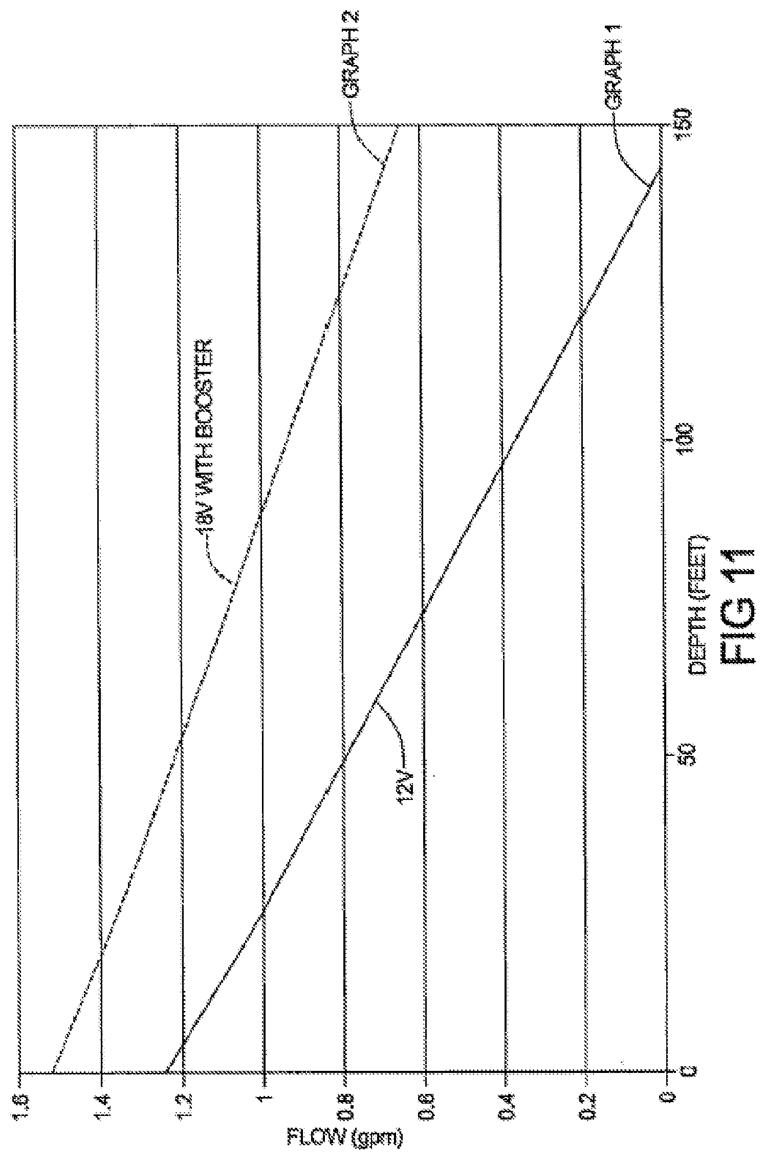
[0059] Referring to FIG. 11 and again to FIGS. 3, 9 and 10, a standard 12 VDC battery such as the battery of an automotive vehicle can provide operative electrical power for operation of brushless DC motor 56. Power consumption for DC motor 56 ranges between approximately 50 to 150 watts, at a current of 1 to 8 Amperes. In comparison, as noted herein the power consumption of known centrifugal pump groundwater sampling pump systems can range from 20 up to 40 Amperes, and commonly require a high current AC power source with conversion to DC power, therefore power consumption of the groundwater sample pump system 126 is reduced by up to approximately 80% compared to known systems. Based on use of a 12 VDC power source 200, graph 1 of FIG. 11 identifies a range of flow rates for groundwater sample pump system 126 of approximately 1.25 gpm at the well surface or ground level 166 reducing to a flow rate of zero at approximately 145 to 150 feet maximum well depth "C".
[0060] According to further aspects, a voltage booster (shown and described in reference to FIG. 12) can be provided, which boosts the 12 VDC voltage up to 18 VDC. Using the voltage booster, the range of flow rates for groundwater sample pump system 126 shown as graph 2 of FIG. 11 can be increased from approximately 1.6 gpm at the well surface or ground level 166 and reducing to a flow rate of approximately 0.7 gpm at 150 feet well depth "C". It is anticipated that using the voltage booster can provide a maximum pump operating depth of approximately 180 feet while still using the same 12 VDC power source 200.
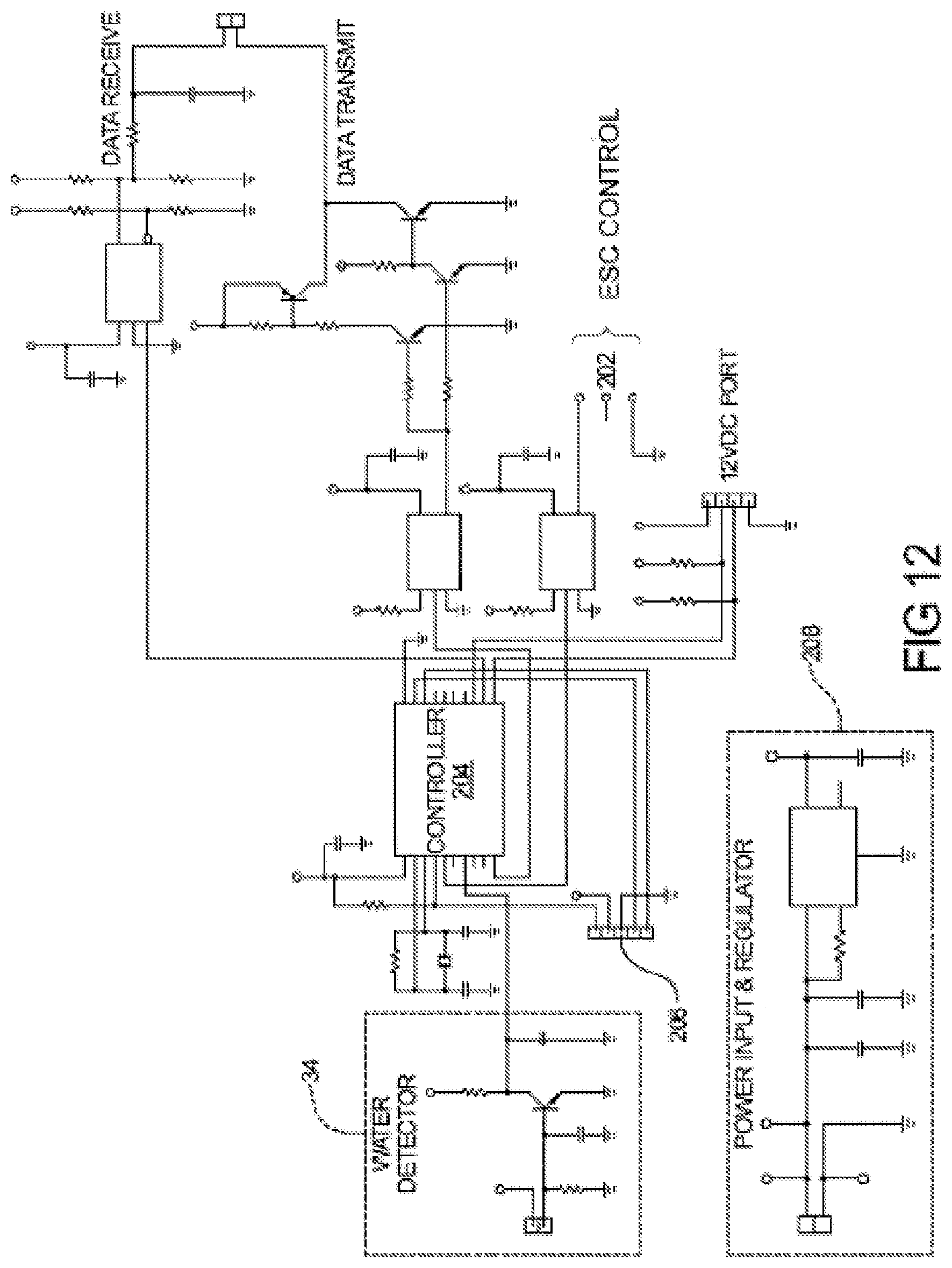
[0061] Referring to FIG. 12, a circuit diagram provides components and data input and output ports for operation of groundwater sample pump system 126. Electronic Speed Control (ESC) for the DC pump is provided at ESC 202 which is connected to a first microcontroller 204. An output of the sensor 34 is also connected to first microcontroller 204, which is also provided with a programming port 206 to enter system operating variables and control set points. A power input and regulator section 208 is provided to control power to operate the brushless DC motor 56, which can include a voltage booster increasing the voltage output from 12 VDC to approximately 18 VDC for increasing an operating depth of the sampling pump assembly 10. The microcontroller 204 can also be used to form an hour meter to track the total time that the DC motor 56 operates. The total time may be displayed to the user by controlling a blinking action (i.e., on/off action) of the LED 180. For example, the LED 180 may be blinked once when the assembly 10 is first powered on if the total run time is between 0-100 hours. The LED 180 may be blinked twice if the total run time is between 100-200 hours, three times if the total run time is between 200-300 hours, etc. The blinking action may be repeated, for example three times, with a short off interval between each on/off sequence. After that the LED 180 may be used in connection with its water sensing operation to indicate when the pump outer housing 12 is submerged in water.
[0062] Referring to FIG. 13 and again to FIG. 9, remote operation and collection of data for groundwater sample pump system 126 can also be provided. A small capacity second battery 210, such as a 9-volt battery, is located on the reel 142 and provides operating power for LED 180 and sensor 34 during initial installation of the sampling pump assembly 10 into the well 164, as well as powering microcontroller 204 and a second microcontroller 212 when the main 12 VDC power source is not connected. Second battery 210 provides sufficient power to test operation of brushless DC motor 56 prior to insertion into the well. Second battery 210 is connected to the second microcontroller 212, which in turn is in communication with and regulates operation of both the LED 180 and the pump speed selector 202. A wireless frequency transceiver, for example a Bluetooth.RTM. protocol wireless transceiver 214, can also be optionally used which communicates with the second microcontroller 212 via a communication path 216. The Bluetooth.RTM. protocol transceiver 214 provides for remote wireless communication between the groundwater sampling pump system 126 and a portable electronic device 218, such as a smart phone, via a wireless signal path 220. The portable electronic device 218 can also communicate data between the sampling pump system 126 and one or more cloud-based subsystems 222 using a wireless transmission path 224.
[0063] In addition to the small second battery 210 that provides temporary power for operation of the LED 180 and sensor 34, an additional larger capacity rechargeable battery 226 can also be provided with reel 142. Battery 226 is sized to provide limited operating time for DC motor 56 to provide sample flow from well 164 when the power source 200 is not available. Battery 226 may be releasably mounted via any suitable mounting bracket or fixture (not shown) to the A-shaped frame 128 for convenience.
[0064] The groundwater sampling pump system 126 can be controlled, operated and have data uploaded or downloaded using the portable electronic device 218, such as a smartphone, tablet, laptop, or virtually any other form of personal electronic device. This allows motor speed control, water level status indication, time of operation of the motor 56, battery state, troubleshooting, historical data such as past motor operating run times and speed settings and other data to be collected and remotely accessed for individual wells. The operator can therefore access other well site data in addition to previous data from well 164 to determine potential settings for operation of groundwater sample pump system 126 at the specific well such as well 164.
[0065] The groundwater sampling pump system 126 offers several advantages. These include: (1) the provision of a pump system having a 12-volt brushless DC motor with circuitry provided in the pump assembly housing and with communication lines for control of the system grouped together with power cables extending from the circuitry of the pump assembly housing to a reel positioned at a ground level position, such that the DC motor operating speed and current are reduced from known sample pump systems thereby improving operating efficiency; (2) the use of a regenerative impeller with the 12-volt brushless DC motor permits the operating speed of the DC motor to be reduced from approximately 12,000 to 15,000 rpm of known sample pump systems having centrifugal impellers down to approximately 8,000 rpm, which significantly reduces cavitation at the impeller, improving pump assembly and impeller life and reducing impact on water samples withdrawn from the well; (3) the reel used to retain the pump assembly power and control cabling includes a built-in controller providing local control of the pump assembly; (4) a water sensor is provided with the pump assembly that is remotely connected to an LED on a panel of the reel providing visual indication when the pump is submerged in the well water volume; (5) a local battery, such as a 9-volt battery, is also provided with the reel that provides power for the sensor prior to connection of a main 12-volt power system to the pump assembly 10; (6) a signal from the sensor provides an additional on-off feature such that the pump is automatically de-energized when the sensor indicates the pump assembly is above the surface of the well water volume; (7) bayonet pins engaged in L-shaped slots of the pump assembly housing provide a releasable assembly; (8) a separate battery in addition to the 9-volt battery provided for LED operation can also be provided in the reel to provide limited operation of the DC motor; and (9) the groundwater sampling pump system 126 can be controlled, operated and have data uploaded or downloaded using remote devices such as a portable phone or tablet allowing motor speed control, water level status indication, time of operation of the motor, battery state, troubleshooting, historical data such as past motor operating run times and speed settings and other data to be collected and remotely accessed for individual wells.
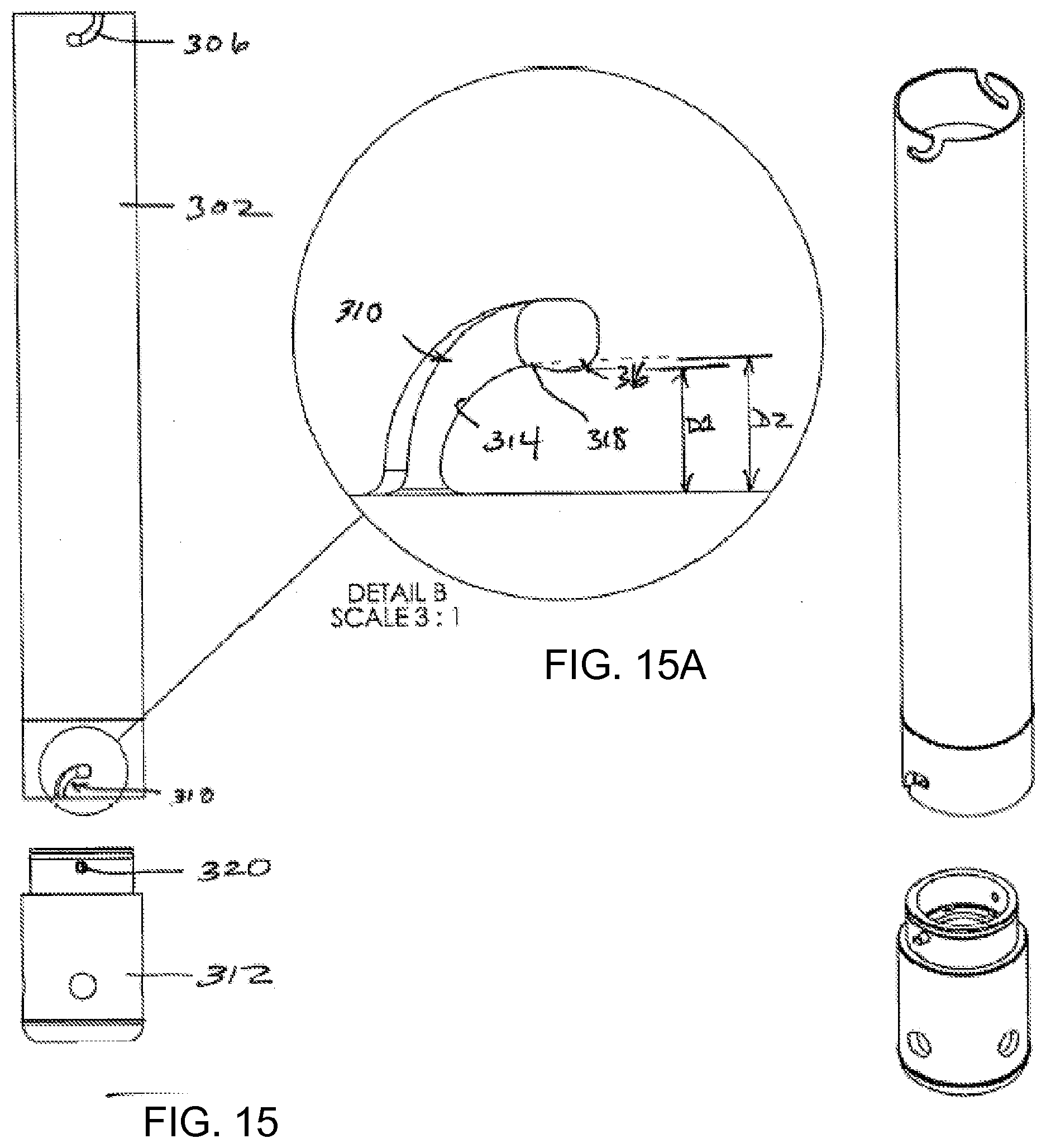
[0066] Referring to FIG. 14, a sampling pump assembly 300 can be seen in accordance with another embodiment of the present disclosure. The pump assembly 300 is substantially identical in construction and operation to the sampling pump assembly 10 discussed above, with the exceptions noted below. The sampling pump assembly 300 includes a housing 302 having a curving J-shaped 306 slot at a first end 304, and a similar curving J-shaped slot 310 in a housing connector 308 associated with a housing inlet end component 312. FIG. 15A illustrates the J-shaped slot 310 in greater detail. Since the construction of the J-shaped slots 306 and 310 are identical in this example, only the detailed construction of J-shaped slot 310 will be provided. Also, it will be appreciated that a pair of J-shaped slots 306 spaced about 180 degrees apart from one another are included on the housing 302, and likewise a pair of the J-shaped slots 310 are included on housing connector 308 and spaced apart about 180 degrees from one another, although only one of each of the J-shaped slots 306 and 310 is visible in FIG. 14.
[0067] J-shaped slot 310 includes a gradually curving section 314 and a slightly enlarged end portion 316. End portion 316 helps to define a point 318 which provides a positive retention feature when bayonet pin 320 (FIG. 15) is urged into the gradually curving section 314 of the J-shaped slot 310 and then urged over point 318.
[0068] With further reference to FIGS. 15, 15A and 16, During travel into and through the curving portion 314, at least one interior gasket 322 (FIG. 16) will begin to be compressed by a distal edge 324 of impeller chamber 326 as the bayonet pin 320 reaches, and moves past, point 318. Point 318 helps to effect a positive "snapping" or "clicking" action/feel as the bayonet pin 320 is urged over the point 318 into full engagement within enlarged end portion 316. Creation of the snapping/clicking action is assisted by the slight compressibility of the internal gasket mentioned above. A positive retention of the bayonet pin 320 and locking action within the enlarged end portion 316 occurs because the enlarged end portion 316 defines a distance D1 which slightly less than a Distance D2. As the bayonet pin 320 is urged over the point 318 and fully engages in the end portion 316, the user feels a definite snapping or clicking action (i.e., tactile feedback), which indicates the bayonet pin is fully seated in the enlarged end portion 316. At this stage, point 318 helps to prevent the bayonet pin 320 from being urged back into the curving portion 314 without some definite counter rotational force applied by the user. This retention, and an excellent fluid tight seal between components 302 and 312 is thus accomplished without the need for any separate sleeves or locking rings, as otherwise required with some previously developed bayonet locking designs.
[0069] FIG. 17 illustrates an easily accessible and replaceable annular motor shaft seal 350 integrated into the pump assembly 300. In this example the motor shaft 57 can be seen engaged with the connecting member 54. Surrounding the connecting member 54 is an annular seal 350. The seal 350 may be preferably be a PTFE FlexiSeal.RTM. sealing element commercially available from the Parker Hannifin Corporation, or any suitable equivalent form of seal. Surrounding the seal 350 may be a sealing retainer 352 having a body portion 354 and a pair of O-rings 356 and 358 seated in upper and lower annular recesses 360 and 362 respectively. Both the seal 350 and the sealing retainer 352 rest on a precision dimensioned spacer 364, which in turn rests on an end face 366 of the motor shaft 57. It will be noted that that outer diameter of the spacer 364 is just slightly greater, for example by about 0.015 inch, than the outer diameter of the body portion 354, but preferably about 0.005 inch smaller than the internal diameter of a recess 363 of a removable bearing retainer component 368. This tight tolerance allows the seal 350 to sit centered to the connecting member 54 throughout the entire assembly shown in FIG. 17 without being moved off center.
[0070] The removable bearing retainer component 368 has a pair of bores 370 which receive a pair of threaded fasteners 372. Threaded fasteners 372 engage within threaded blind holes in the end face 366 of the motor shaft 57. Threaded fasteners 372 enable the bearing retainer component 368 to be quickly and easily removed in the field by an individual using only a conventional hand tool such as an Allen wrench, screwdriver, etc. Disassembly and reassembly can be performed in the field without complex procedures. When disassembled, the PTFE FlexiSeal.RTM. sealing element 350 and/or the sealing retainer 352 can thus be easily replaced without the need for special tools. The concentric arrangement of the sealing retainer 352 with the PTFE FlexiSeal.RTM. sealing element 350 further enables the sealing retainer 352 to be essentially perfectly concentrically aligned with sealing element 350 and the motor shaft 57, which further helps to ensure a watertight seal between the bearing retainer component 368 and the motor shaft 57. Referring to FIGS. 18-20, various views of an impeller retainer 380 in accordance with another embodiment of the present disclosure may be seen. FIGS. 21-24 illustrate various views of another embodiment of an impeller housing 382 that may be used with the impeller retainer 380. Impeller retainer 380 forms a pump inlet with a ramped surface 384 (FIG. 20) that helps even more efficiently direct incoming flow into a volute portion 386 (FIG. 18). In FIGS. 18 and 20, volute portions 384a and 386a communicate with each other. Similarly, in FIGS. 21-23, the impeller housing 382 includes a ramped portion 388 that even more efficiently helps to direct the flow out from volute portion 390. In FIGS. 21 and 23, the flow enters the volute portion 390 at point 390a and leaves at portion 390b of the volute portion 390. As the flow leaves portion 390b it enters the ramped portion 388 in FIG. 21. Accordingly, the ramped portions 384 and 388 enable even more efficiently directing flow into and out from the volute formed by volute portions 386 and 390.
[0071] Example embodiments are provided so that this disclosure will be thorough, and will fully convey the scope to those who are skilled in the art. Numerous specific details are set forth such as examples of specific components, devices, and methods, to provide a thorough understanding of embodiments of the present disclosure. It will be apparent to those skilled in the art that specific details need not be employed, that example embodiments may be embodied in many different forms and that neither should be construed to limit the scope of the disclosure. In some example embodiments, well-known processes, well-known device structures, and well-known technologies are not described in detail.
[0072] The terminology used herein is for the purpose of describing particular example embodiments only and is not intended to be limiting. As used herein, the singular forms "a," "an," and "the" may be intended to include the plural forms as well, unless the context clearly indicates otherwise. The terms "comprises," "comprising," "including," and "having," are inclusive and therefore specify the presence of stated features, integers, steps, operations, elements, and/or components, but do not preclude the presence or addition of one or more other features, integers, steps, operations, elements, components, and/or groups thereof. The method steps, processes, and operations described herein are not to be construed as necessarily requiring their performance in the particular order discussed or illustrated, unless specifically identified as an order of performance. It is also to be understood that additional or alternative steps may be employed.
[0073] When an element or layer is referred to as being "on," "engaged to," "connected to," or "coupled to" another element or layer, it may be directly on, engaged, connected or coupled to the other element or layer, or intervening elements or layers may be present. In contrast, when an element is referred to as being "directly on," "directly engaged to," "directly connected to," or "directly coupled to" another element or layer, there may be no intervening elements or layers present. Other words used to describe the relationship between elements should be interpreted in a like fashion (e.g., "between" versus "directly between," "adjacent" versus "directly adjacent," etc.). As used herein, the term "and/or" includes any and all combinations of one or more of the associated listed items.
[0074] Although the terms first, second, third, etc. may be used herein to describe various elements, components, regions, layers and/or sections, these elements, components, regions, layers and/or sections should not be limited by these terms. These terms may be only used to distinguish one element, component, region, layer or section from another region, layer or section. Terms such as "first," "second," and other numerical terms when used herein do not imply a sequence or order unless clearly indicated by the context. Thus, a first element, component, region, layer or section discussed below could be termed a second element, component, region, layer or section without departing from the teachings of the example embodiments.
[0075] Spatially relative terms, such as "inner," "outer," "beneath," "below," "lower," "above," "upper," and the like, may be used herein for ease of description to describe one element or feature's relationship to another element(s) or feature(s) as illustrated in the figures. Spatially relative terms may be intended to encompass different orientations of the device in use or operation in addition to the orientation depicted in the figures. For example, if the device in the figures is turned over, elements described as "below" or "beneath" other elements or features would then be oriented "above" the other elements or features. Thus, the example term "below" can encompass both an orientation of above and below. The device may be otherwise oriented (rotated 90 degrees or at other orientations) and the spatially relative descriptors used herein interpreted accordingly.
[0076] The foregoing description of the embodiments has been provided for purposes of illustration and description. It is not intended to be exhaustive or to limit the disclosure. Individual elements or features of a particular embodiment are generally not limited to that particular embodiment, but, where applicable, are interchangeable and can be used in a selected embodiment, even if not specifically shown or described. The same may also be varied in many ways. Such variations are not to be regarded as a departure from the disclosure, and all such modifications are intended to be included within the scope of the disclosure.
* * * * *
D00000
D00001
D00002
D00003
D00004
D00005
D00006
D00007
D00008
D00009
D00010
D00011
D00012

D00013

D00014

XML
uspto.report is an independent third-party trademark research tool that is not affiliated, endorsed, or sponsored by the United States Patent and Trademark Office (USPTO) or any other governmental organization. The information provided by uspto.report is based on publicly available data at the time of writing and is intended for informational purposes only.
While we strive to provide accurate and up-to-date information, we do not guarantee the accuracy, completeness, reliability, or suitability of the information displayed on this site. The use of this site is at your own risk. Any reliance you place on such information is therefore strictly at your own risk.
All official trademark data, including owner information, should be verified by visiting the official USPTO website at www.uspto.gov. This site is not intended to replace professional legal advice and should not be used as a substitute for consulting with a legal professional who is knowledgeable about trademark law.