Pigment Particle Layer Of Electrophoretic Display And Electrophoretic Display Device
Kind Code
U.S. patent application number 16/649043 was filed with the patent office on 2020-08-13 for pigment particle layer of electrophoretic display and electrophoretic display device. The applicant listed for this patent is GUANGZHOU OED TECHNOLOGIES, INC.. Invention is credited to YU CHEN, XI ZENG.
| Application Number | 20200255670 16/649043 |
| Document ID | 20200255670 / US20200255670 |
| Family ID | 1000004840160 |
| Filed Date | 2020-08-13 |
| Patent Application | download [pdf] |


| United States Patent Application | 20200255670 |
| Kind Code | A1 |
| ZENG; XI ; et al. | August 13, 2020 |
PIGMENT PARTICLE LAYER OF ELECTROPHORETIC DISPLAY AND ELECTROPHORETIC DISPLAY DEVICE
Abstract
The invention provides pigment particles and an organic modification layer formed on a surface of the pigment particles; the organic modification layer is a surfactant layer or a polymer material layer formed on the surface of the pigment particles; an organic matter content W.sub.surf of the specific surface area of the pigment particles is in a range of 0.1-2% g/m.sup.2. The pigment particles provided by the invention have good stability, and the electrophoretic display prepared by using the pigment particles of the invention has good optical performance.
| Inventors: | ZENG; XI; (Guangzhou, CN) ; CHEN; YU; (Guangzhou, CN) | ||||||||||
| Applicant: |
|
||||||||||
|---|---|---|---|---|---|---|---|---|---|---|---|
| Family ID: | 1000004840160 | ||||||||||
| Appl. No.: | 16/649043 | ||||||||||
| Filed: | August 24, 2018 | ||||||||||
| PCT Filed: | August 24, 2018 | ||||||||||
| PCT NO: | PCT/CN2018/102283 | ||||||||||
| 371 Date: | April 20, 2020 |
| Current U.S. Class: | 1/1 |
| Current CPC Class: | C01P 2006/60 20130101; C01P 2006/12 20130101; G02F 1/167 20130101; C08F 292/00 20130101; C01P 2004/62 20130101; C09C 3/10 20130101 |
| International Class: | C09C 3/10 20060101 C09C003/10; G02F 1/167 20060101 G02F001/167; C08F 292/00 20060101 C08F292/00 |
Foreign Application Data
| Date | Code | Application Number |
|---|---|---|
| Sep 20, 2017 | CN | 201710854272.1 |
Claims
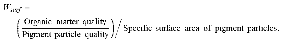
1. A pigment particle layer of an electrophoretic display, comprising pigment particles and an organic modification layer formed on a surface of the pigment particles; the organic modification layer is a surfactant layer or a polymer material layer formed on the surface of the pigment particles; an organic matter content W.sub.surf of the specific surface area of the pigment particles is in a range of 0.1-2% g/m.sup.2, the organic matter content W.sub.surf is expressed as that: W surf = ( Organic matter quality Pigment particle quality ) / Specific surface area of pigment particles . ##EQU00004##
2. The pigment particle layer of the electrophoretic display according to claim 1, wherein a thickness of the organic modification layer is greater than 20nm.
3. The pigment particle layer of the electrophoretic display according to claim 1, wherein a thickness of the organic modification layer is between 30 nm and 100 nm.
4. The pigment particle layer of the electrophoretic display according to claim 1, wherein a shape of the pigment particles is irregular.
5. The pigment particle layer of the electrophoretic display according to claim 1, wherein a particle size of the pigment particles is in a range of 0.1 micrometer to 1 micrometer.
6. The pigment particle layer of the electrophoretic display according to claim 1, wherein the organic matter content W.sub.surf of the specific surface area of the pigment particles is further in the range of 0.25-1.6% g/m.sup.2.
7. The pigment particle layer of the electrophoretic display according to claim 1, wherein the pigment particles are inorganic salts and/or inorganic oxide pigments.
8. The pigment particle layer of the electrophoretic display according to claim 1, wherein the organic modification layer is a surfactant layer or a polymer material layer adsorbed on the surface of the pigment particles, or the organic modification layer is a polymer material layer grafted on the surface of the pigment particles.
9. An electrophoretic display device, comprising a body of the electrophoretic display device, an electrophoretic solution disposed in the body of the electrophoretic display device, and a pigment particle layer, wherein the pigment particle layer comprises pigment particles and an organic modification layer formed on a surface of the pigment particles; the organic modification layer is a surfactant layer or a polymer material layer formed on the surface of the pigment particles; an organic matter content W.sub.surf of the specific surface area of the pigment particles is in a range of 0.1-2% g/m.sup.2, the organic matter content W.sub.surf is expressed as that: W surf = ( Organic matter quality Pigment particle quality ) / Specific surface area of pigment particles . ##EQU00005##
10. The electrophoretic display device according to claim 9, wherein the body of the electrophoretic display device is a microcapsule, a microcup or a micropool.
11. The electrophoretic display device according to claim 9, wherein a thickness of the organic modification layer is greater than 20 nm.
12. The electrophoretic display device according to claim 9, wherein a thickness of the organic modification layer is between 30 nm and 100 nm.
13. The electrophoretic display device according to claim 9, wherein a shape of the pigment particles is irregular.
14. The electrophoretic display device according to claim 9, wherein a particle size of the pigment particles is in a range of 0.1 micrometer to 1 micrometer.
15. The electrophoretic display device according to claim 9, wherein the organic matter content W.sub.surf of the specific surface area of the pigment particles is further in the range of 0.25-1.6% g/m.sup.2.
16. The electrophoretic display device according to claim 9, wherein the pigment particles are inorganic salts and/or inorganic oxide pigments.
17. The electrophoretic display device according to claim 9, wherein the organic modification layer is a surfactant layer or a polymer material layer adsorbed on the surface of the pigment particles, or the organic modification layer is a polymer material layer grafted on the surface of the pigment particles.
Description
FIELD OF THE INVENTION
[0001] The invention relates to an electrophoretic display technology field, and more particularly to a pigment particle layer of an electrophoretic display and an electrophoretic display device.
BACKGROUND OF THE INVENTION
[0002] Electronic paper, a "thin, soft, rewritable display like paper", is becoming more widespread in everyday applications. The ways to realize electronic paper technology mainly include cholesterol liquid crystal display technology, electrophoretic display technology (EPD), and electrowetting display technology, but only electrophoretic display technology can achieve bistable and mass production. The principle of electrophoretic display is that in a liquid, different kinds of particles are dispersed, and the particles can be charged on the surface or neutral on the surface without charge. In the case of an external electric field, particles with a charge on the surface will move in a specific direction under the force of the electric field. For example, particles with a negative charge on the surface will move to the relatively high voltage side, and particles with a positive charge on the surface will move to the relatively low voltage side. Thus, particles with different surface charges are gathered in different positions in this system. By selecting particles and solvents of different colors, the effect of displaying different colors under different voltage conditions can be achieved.
[0003] For electrophoretic displays and related applications, their display performance and stability depend on the surface modification effect and stability of the black, white, or other colored particles used for display. Therefore, a pigment particle needs to be researched, which can increase the stability of the pigment particle in the solution, and can make the display have good photoelectric performance.
SUMMARY OF THE INVENTION
[0004] In view of the shortcomings of the prior art, the object of the invention is to provide pigment particles and electrophoretic display units for electrophoretic display that have good photoelectric properties in a solution.
[0005] In order to solve the above technical problems, the invention provides a pigment particle layer of an electrophoretic display, including pigment particles and an organic modification layer formed on a surface of the pigment particles; the organic modification layer is a surfactant layer or a polymer material layer formed on the surface of the pigment particles; an organic matter content W.sub.surf of the specific surface area of the pigment particles is in a range of 0.1-2% g/m.sup.2, the organic matter content W.sub.surf is expressed as that:
W surf = ( Organic matter quality Pigment particle quality ) / Specific surface area of pigment particles . ##EQU00001##
[0006] Preferably, the thickness of the organic modification layer is greater than 20 nm.
[0007] Preferably, the thickness of the organic modification layer is between 30 nm and 100 nm.
[0008] Preferably, the shape of the pigment particles is irregular.
[0009] Preferably, the particle size of the pigment particles is in a range of 0.1 micrometer to 1 micrometer.
[0010] Preferably, the organic matter content W.sub.surf of the specific surface area of the pigment particles is further in the range of 0.25-1.6% g/m.sup.2.
[0011] Preferably, the pigment particles are inorganic salts and/or inorganic oxide pigments.
[0012] Preferably, the organic modification layer is a surfactant layer or a polymer material layer adsorbed on the surface of the pigment particles, or the organic modification layer is a polymer material layer grafted on the surface of the pigment particles.
[0013] The invention also provides an electrophoretic display device, which includes a body of the electrophoretic display device, an electrophoretic solution disposed in the body of the electrophoretic display device, and the pigment particle layer described above.
[0014] Preferably, the body of the electrophoretic display device is a microcapsule, a microcup or a micropool.
[0015] The pigment particle layer provided by the invention have good stability, and the electrophoretic display device prepared by using the pigment particle layer of the invention has good optical performance.
DETAILED DESCRIPTION OF EMBODIMENTS
[0016] The technical solutions of the invention are described in further detail below with reference to the accompanying drawings and specific embodiments, so that those skilled in the art can better understand the invention and can implement it, but the examples given are not intended to limit the invention.
[0017] This embodiment provides a pigment particle layer of an electrophoretic display, including pigment particles and an organic modification layer formed on a surface of the pigment particles; the organic modification layer is a surfactant layer or a polymer material layer formed on the surface of the pigment particles; in electrophoretic display, there are many cases where two or more particles with different surface charges are present in one solution. At least two different particles have opposite surface charges. One particle has a positive charge and the other particle has a negative charge. There is also a strong electrostatic attraction between the two particles.
[0018] According to the DLVO theory of colloid chemistry, the van der Waals interaction force between two particles can be expressed by the following formula (References: Principles of Colloid and Surface Chemistry, third edition, by Paul C. Hiemenz and Raj Rajagopalan, Chapter 13):
.0. net = 64 k B Tn .infin. .kappa. - 1 0 2 exp ( - .kappa. d ) - ( A 12 .pi. ) d - 2 ##EQU00002##
[0019] The calculated Van der Waals force distance is generally less than 10 nm, and usually there is a weak attraction between the two particles at about 4-6 nm, which causes the two particles to attract each other and produce aggregates. In electrophoretic display, there are many cases where two or more particles with different surface charges are present in one solution. At least two different particles have opposite surface charges, one particle has a positive charge and the other particle has a negative charge. There is also a strong electrostatic attraction between these two particles. According to colloid theory, this electrostatic force can be expressed by the following formula (References: Principles of Colloid and Surface Chemistry, third edition, by Paul C. Hiemenz and Raj Rajagopalan, Chapter 11):
O.sub.n=(4.pi.R.sub.s.sup.2.epsilon..phi..sub.0.sup.2)exp(-.kappa.S)/(S+- 2R.sub.s)
[0020] The distance of electrostatic force will be a little longer than the distance of Van der Waals force, generally above 10 nm, and can even reach 20-50 nm.
[0021] Based on the above analysis, it is desirable that the thickness of the organic modified layer on the surface of the particles be at least 20 nm, so that the distance between the two particles can be maintained at more than 40 nm. This can reduce the van der Waals force and electrostatic attraction between the particles, and increase the dispersion and stability of the particles in the electrophoretic display system.
[0022] Existing methods for measuring the thickness of the organic modified layer on the particle surface include TEM, SEM, dynamic light scattering, and static light scattering methods. However, these test methods are quite expensive, the test methods are more complicated, and the requirements for testers are relatively high. They require deep professional knowledge. Therefore, from this aspect, the better expression method is the organic content of the modified particles. At the same time, the particle size and specific surface area of different pigment particles are considered to be very different. For example, when the average particle size of calcium carbonate particles is 1 micron, the specific surface area is usually in the range of 5-10 m.sup.2/g; the specific surface area of fumed silica can be as high as 100 m.sup.2/g or even 200-300 m.sup.2/g. In this way, the same modified organic content will cause a great difference in the thickness of the corresponding organic layer on different pigment particles. As a result, pigment particles modified with the same organic content have completely different properties in dispersion and stability in solution. Based on this consideration, the organic matter content W.sub.surf of the specific surface area of the pigment particles is a better characterization method.
[0023] In the present embodiment, the organic matter content W.sub.surf of the specific surface area of the pigment particles is in a range of 0.1-2% g/m.sup.2, the organic matter content W.sub.surf is expressed as that:
W surf = ( Organic matter quality Pigment particle quality ) / Specific surface area of pigment particles . ##EQU00003##
[0024] On the one hand, it is desirable that the polymer content W.sub.surf per unit specific surface area is high enough so that the thickness of the polymer layer is large enough to isolate Van der Waals forces and electrostatic attractive forces. However, on the other hand, if W.sub.surf is too high, the thickness of the polymer layer will be too large. When the pigment particles move under an external electric field, it will bring greater resistance and reduce the migration rate of the particles under the electric field. In this way, W.sub.surf needs to be in a suitable range, which can provide sufficient dispersion and stability for the pigment particles without seriously reducing the migration rate of the particles.
[0025] In a preferred embodiment, the organic matter content W.sub.surf of the specific surface area of the pigment particles is further in the range of 0.25-1.6% g/m.sup.2.
[0026] In a preferred embodiment, the organic modification layer is an organic modification layer having a thickness greater than 20 nm. In a further preferred embodiment, the organic modification layer is further an organic modification layer having a thickness between 30 nm and 100 nm. In a further preferred embodiment, the organic modification layer is an organic modification layer having a thickness between 35 nm and 50 nm.
[0027] In a preferred embodiment, the pigment particles are irregularly shaped pigment particles.
[0028] In a preferred embodiment, the particle size of the pigment particles ranges from 0.1 micrometer to 1 micrometer. In order to achieve electrophoretic display, the particle size of these pigment particles is usually relatively small. According to the principle of thermodynamics, such small particles will tend to aggregate together in the solvent instead of being uniformly dispersed in the solvent. The causes of particles agglomerating in solution include van der Waals force, electrostatic attraction (between two particles with opposite surface charges), and bridging effects caused by polymers in the solution. Therefore, the particle size of the pigment particles in the range of 0.1 micrometers to 1 micrometers has a better display effect, and is not affected by the interaction force between the particles.
[0029] In a preferred embodiment, the pigment particles are pigment particles of an inorganic salt and/or an inorganic oxide pigment.
[0030] The inorganic salt and the inorganic oxide pigments include silica, titanium dioxide, calcium oxide, chromium oxide, zinc dioxide, copper oxide, lead oxide, carbon black, silicate, titanium yellow, chrome yellow, lead chrome green, manganese purple, iron blue, cobalt blue, zinc white, cadmium yellow, barium sulfate, molybdenum orange, ultramarine blue, azure blue, emerald green, emerald green, and other types of inorganic salt or inorganic oxide pigments.
[0031] In a preferred embodiment, the color selection of the pigment particles may be white, black, or other colors, such as red, yellow, blue, green, brown, and other colors.
[0032] In a preferred embodiment, the organic modification layer is a surfactant layer or a polymer material layer adsorbed on the surface of the pigment particles, or the organic modification layer is a polymer material layer grafted on the surface of the pigment particles. When modifying the particle surface, the method of adsorbing surfactants or polymers is relatively simple, but the adsorption of these organic substances is generally physically adsorbed on the particle surface, or chemical adsorption in the form of ionic bonds, hydrogen bonds, and the like. However, these adsorptions are usually a reversible process, and the modification results of the particles do not have long-term stability, which affects the correlation and long-term reliability of the electrophoretic display. But it is a better method to graft the polymer to the surface of the particle by covalent bonding, which can give the particle a long-term surface modification.
[0033] In a further preferred embodiment, the grafting method is to use a polymer monomer to perform a polymerization reaction in a solution, and at the same time, the polymer after the reaction is grafted with a coupling agent existing on the surface of the pigment particles. Common coupling agents include silane-based coupling agents, titanate-based coupling agents, aluminate-based coupling agents, and the like. The polymer monomer may be any compound that can be used for polymerization, including but not limited to compounds such as octadecyl methacrylate, dodecyl methacrylate, tetradecyl methacrylate, ethyl methacrylate, butyl methacrylate, t-butyl methacrylate, cyclohexyl methacrylate, isobornyl methacrylate, benzyl methacrylate, styrene, 4-vinylpyridine, N-vinylpyrrolidone, trifluoroethyl methacrylate, methacrylic acid, or mixtures, composites or derivatives thereof.
[0034] In a preferred embodiment, the pigment particles are pigment particles of an organic pigment. Organic pigments include various natural or synthetic organic pigments. For example, organic yellow pigments (Aiarylide yellow, Arylide yellow, Hansa yellow, Benzidine yellow, etc.), organic orange pigments (Perinone orange, diarylide orange, etc.), organic blue pigments (Ultramarine blue, Indanthrone blue, etc.), organic red pigments (Anthraquinoid red, Perylene red, etc.) or organic pigments of other colors.
[0035] This embodiment also provides an electrophoretic display device, which includes a body of the electrophoretic display device, an electrophoretic solution disposed in the body of the electrophoretic display device, and the pigment particle layer described above.
[0036] In a preferred embodiment, the body of the electrophoretic display device is a microcapsule, a microcup or a micropool.
[0037] In this embodiment, pigment particles of the grafted polymer are prepared according to the following preparation method to obtain particles 1-4.
[0038] In a 1000 ml reaction bottle, add 200 g of pigment, a certain amount of coupling agent, 200 g of lauryl ester, and 400 g of toluene. The system was kept inert under a nitrogen atmosphere, and mixed at a stirring speed of 200 rpm for 20 minutes. Under a nitrogen environment and a condensing reflux device, the temperature of the reaction mixture was slowly raised to 50.degree. C., an initiator was added, and the reaction was carried out for 16 hours. The reaction product was collected by centrifugation at 3500 RPM, and the product was washed with toluene during the collection. After the electrophoretic particles are collected, the organic content of the test particles, the test data, and the calculated organic specific content of the pigment particles per unit surface area W.sub.surf are listed in Table 1.
TABLE-US-00001 TABLE 1 Organic Organic matter matter content Specific content per unit surface per unit specific Sample Pigment area Organic mass of surface name particle Color Supplier (m.sup.2/g) content pigment area (g/m.sup.2) Particle 20F944 Black Shepherd 22 17.07% 20.58% 0.936% 1 Color Co. Particle 20C920 Black Shepherd 11 5.97% 6.35% 0.577% 2 Color Co. Particle Ti-Pure White Du Pont 9 4.26% 4.45% 0.494% 3 105 Particle RO4597 Red Elementis 7.5 4.58% 4.80% 0.640% 4
[0039] Using the particles 1-4 obtained above to prepare electrophoretic display samples 1-3, the preparation method is as follows:
[0040] Electrophoresis solution configuration: dispersing an appropriate amount of white negative electrophoresis particles and black neutral electrophoresis particles or white negative electrophoresis particles and red positive electrophoresis particles, stabilizers and a charge control agent in an alkane solvent, preparing an electrophoretic display solution, and dispersing and uniformly using it at a certain temperature.
[0041] Synthesis of microcapsule display microunits by complex agglomeration method: weighing a certain amount of deionized water and add it to a 10 L glass sandwich reactor, then weighing a certain amount of gelatin and adding it to deionized water to stir and dissolve. The dissolution temperature is 42.degree. C. At the same time weighing a certain amount of acacia gum and deionized water, stirring and dissolving in another 4 L glass reaction kettle, and the dissolution temperature is 40.degree. C. After the gelatin is completely dissolved, adding the electrophoretic display solution, adjusting the rotation speed, and stirring and dispersing for 45 minutes, and then adding the completely dissolved gum arabic solution, adjusting the appropriate rotation speed and continue to stir and disperse for 30 minutes. Then adjusting the pH value to 4.5 with a 10% acetic acid aqueous solution, adjusting the appropriate speed and stirring for 30 minutes. The temperature of the reactor was reduced to 10.degree. C., and the temperature reduction time was 3 hours. A 50% glutaraldehyde solution was added, and the reaction temperature was raised to 25 .degree. C. to crosslink and cure the microcapsules for 10 hours. Collecting the microcapsules and using a vibrating sieve method with a microporous filter to select capsules of appropriate particle size for use.
[0042] Microcapsule coating and electrophoretic display preparation: adjusting the microcapsules to a suitable pH value of about 5.0, then mixing and stirring with 5 parts by weight of adhesive, 45 parts by weight of microcapsules, and 50 parts by weight of water. The dispersant and thickener were added and stirred at 45.degree. C. to prepare an electronic ink. The electronic ink was coated on an ITO film and dried to form an electrophoretic display layer. The thickness of the test electrophoretic display layer was 28 microns. Finally, a layer of glue is scraped on the electrophoretic display layer, laser-cut to a suitable size, and then laminated to the TFT to seal it, thereby completing the preparation of the electrophoretic display device.
[0043] The prepared electrophoretic display was used to test the photoelectric performance of the electrophoretic display device at a specific temperature by using a color measuring instrument Eye-one. The photoelectric properties of samples 1-3 are shown in Table 2.
TABLE-US-00002 TABLE 2 Sample White Color L* L* a* b* name particles particles White Black Color Color CR Sample Particle Particle 73.63 11.59 0.13 -2.24 34.29 1 3 1 Sample Particle Particle 75.45 16.45 -0.16 0.04 22.40 2 3 2 Sample Particle Particle 70.63 43.67 31.37 15.68 3.06 3 3 4
[0044] It can be seen from the data of Table 1 and Table 2. The prepared samples all have good photoelectric performance. Among them, the black-and-white display effect of the black and white samples of samples 1 and 2 is very good, the contrast ratio meets the requirements, and the red and white samples of display 3 have good color effects. It shows that the sample obtained by reasonable setting of the Wsurf value in this embodiment has good photoelectric performance. At the same time, the pigment particles prepared in this embodiment also have good stability when dispersed in a solution.
[0045] The above description is only the preferred embodiments of the invention, and thus does not limit the patent scope of the invention. Any equivalent structure or equivalent process transformation made by using the description and drawings of the invention, or directly or indirectly used in other related technical fields, is also included in the patent protection scope of the invention.
* * * * *
uspto.report is an independent third-party trademark research tool that is not affiliated, endorsed, or sponsored by the United States Patent and Trademark Office (USPTO) or any other governmental organization. The information provided by uspto.report is based on publicly available data at the time of writing and is intended for informational purposes only.
While we strive to provide accurate and up-to-date information, we do not guarantee the accuracy, completeness, reliability, or suitability of the information displayed on this site. The use of this site is at your own risk. Any reliance you place on such information is therefore strictly at your own risk.
All official trademark data, including owner information, should be verified by visiting the official USPTO website at www.uspto.gov. This site is not intended to replace professional legal advice and should not be used as a substitute for consulting with a legal professional who is knowledgeable about trademark law.