Wide-angle Lens, Camera Module And Vehicle Camera
Kind Code
U.S. patent application number 16/858636 was filed with the patent office on 2020-08-13 for wide-angle lens, camera module and vehicle camera. The applicant listed for this patent is JIANGXI LIANCHUANG ELECTRONIC CO., LTD.. Invention is credited to YUMIN BAO, XUMING LIU, JIYONG ZENG.
| Application Number | 20200254941 16/858636 |
| Document ID | 20200254941 / US20200254941 |
| Family ID | 1000004795461 |
| Filed Date | 2020-08-13 |
| Patent Application | download [pdf] |


| United States Patent Application | 20200254941 |
| Kind Code | A1 |
| BAO; YUMIN ; et al. | August 13, 2020 |
WIDE-ANGLE LENS, CAMERA MODULE AND VEHICLE CAMERA
Abstract
The disclosure provides wide-angle lens, an imaging device, a camera module and a vehicle camera. From an object side to an image side, the wide-angle lens sequentially includes: a first lens group with a refractive power, wherein the first lens group includes a first lens with a negative refractive power, a second lens with a negative refractive power and a third lens with a positive refractive power from the object side surface to the image side surface; a second lens group with a positive refractive power, wherein the second lens group includes a fourth lens with a negative refractive power, a fifth lens with a positive refractive power and a sixth lens with a positive refractive power; and a stop disposed between the first lens group and the second lens group.
| Inventors: | BAO; YUMIN; (NANCHANG, CN) ; LIU; XUMING; (NANCHANG, CN) ; ZENG; JIYONG; (NANCHANG, CN) | ||||||||||
| Applicant: |
|
||||||||||
|---|---|---|---|---|---|---|---|---|---|---|---|
| Family ID: | 1000004795461 | ||||||||||
| Appl. No.: | 16/858636 | ||||||||||
| Filed: | April 26, 2020 |
Related U.S. Patent Documents
| Application Number | Filing Date | Patent Number | ||
|---|---|---|---|---|
| PCT/CN2019/113101 | Oct 24, 2019 | |||
| 16858636 | ||||
| Current U.S. Class: | 1/1 |
| Current CPC Class: | G02B 13/06 20130101; H04N 5/2254 20130101; G02B 9/62 20130101; B60R 11/04 20130101; H04N 5/2252 20130101 |
| International Class: | B60R 11/04 20060101 B60R011/04; G02B 9/62 20060101 G02B009/62; H04N 5/225 20060101 H04N005/225; G02B 13/06 20060101 G02B013/06 |
Foreign Application Data
| Date | Code | Application Number |
|---|---|---|
| Dec 12, 2018 | CN | 201811522963.2 |
Claims
1. A wide-angle lens, from an object side to an image side, sequentially comprising: a first lens group with a refractive power, wherein the first lens group comprises a first lens with a negative refractive power, a second lens with a negative refractive power and a third lens with a positive refractive power from the object side surface to the image side surface, an object side surface of the first lens is convex, an image side surface of the first lens is concave, an object side surface of the second lens is convex, an image side surface of the second lens is concave, an object side surface and an image side surface of the third lens are both convex; a second lens group with a positive refractive power, wherein the second lens group comprises a fourth lens with a negative refractive power, a fifth lens with a positive refractive power and a sixth lens with a positive refractive power, the fourth lens and the fifth lens form a cemented doublet; a stop disposed between the first lens group and the second lens group; wherein the first lens, the second lens, the third lens, the fourth lens, the fifth lens and the sixth lens each are glass lenses, and the optical center of every lens is located on the same straight line.
2. The wide-angel lens as claimed in claim 1, wherein the wide-angle lens meets the expression: -10<.phi..sub.2/.phi..sub.1<6, where .phi..sub.2 represents a refractive power of the second lens, .phi..sub.1 represents a refractive power of the first lens group.
3. The wide-angel lens as claimed in claim 1, wherein the wide-angle lens meets the expression: -15.times.10.sup.-6/.degree. C.<(dN/dT).sub.2+(dN/dT)<2.times.10.sup.-6/.degree. C., where (dN/dT).sub.2 represents a temperature coefficient of refractive index of the second lens, (dN/dT).sub.6 represents a temperature coefficient of refractive index of the sixth lens.
4. The wide-angel lens as claimed in claim 1, wherein the wide-angle lens meets the expression: 0.3 < ? / .PHI. < 0.8 , ? indicates text missing or illegible when filed ##EQU00002## where .phi.represents a refractive power of the second lens group, .phi. represents a refractive power of the wide-angle lens.
5. The wide-angel lens as claimed in claim 1, wherein the wide-angle lens meets the expression: -0.1<.phi..sub.2/r.sub.21<0, where .phi..sub.2 represents a refractive power of the second lens, r.sub.21 represents a radius of curvature of an object side surface of the second lens.
6. The wide-angel lens as claimed in claim 1, wherein the wide-angle lens meets the expression: 0.ltoreq.(|.DELTA.IH/.DELTA..theta.|.sub.max-|.DELTA.IH/.DELTA..theta.|.s- ub.min)/(f*tan(.DELTA..theta.)).ltoreq.0.25, where .DELTA.IH represents a change of image height of the wide-angle lens, .DELTA..theta. represents a change of half-FOV of the wide-angle lens, |.DELTA.IH/.DELTA..theta.|.sub.max represents the maximum angular resolution, |.DELTA.IH/.DELTA..theta..sub.min represents the minimum angular resolution, f represent an effective focal length of the wide-angle lens.
7. The wide-angel lens as claimed in claim 1, wherein the first lens, the second lens, the third lens, the fourth lens, and the fifth lens each are glass spherical lenses, and the sixth lens is a glass aspherical lens.
8. The wide-angel lens as claimed in claim 1, wherein the fourth lens is a bi-concave lens, the fifth lens is a bi-convex lens, an object side surface of the sixth lens is convex.
9. The wide-angel lens as claimed in claim 1, wherein an F number of the wide-angle lens is not greater than 1.8, a field of view of the wide-angle lens is between 80.degree.-140.degree., and a total optical length of the wide-angle lens is less than 23 mm.
10. The wide-angel lens as claimed in claim 1, wherein the wide-angle lens meets the expression: d.sub.12>d.sub.23>d.sub.56; where d.sub.12 represents a distance between the first lens and the second lens on the optical axis, d.sub.23 represents a distance between the second lens and the third lens on the optical axis, d.sub.56 represents a distance between the fifth lens and the sixth lens on the optical axis.
11. The wide-angel lens as claimed in claim 1, wherein the wide-angel lens meets the expressions: D.sub.1>D.sub.2>D.sub.3; D.sub.6>D.sub.5; where D.sub.1 represents the maximum diameter of the first lens, D.sub.2 represents the maximum diameter of the second lens, D.sub.3 represents the maximum diameter of the third lens, D.sub.5 represents the maximum diameter of the fifth lens, D.sub.6 represents the maximum diameter of the sixth lens.
12. A camera module, comprising a wide-angle lens and an image sensor opposite to the wide-angle lens, wherein, from an object side to an image side, the wide-angle lens sequentially comprises: a first lens group comprising a first lens, a second lens and a third lens, wherein the first lens has a negative refractive power, a convex object side surface and a concave image side surface, the second lens has a negative refractive power, a convex object side surface and a concave image side surface, the third lens has a positive refractive power, a convex object side surface and a convex image side surface; a stop; a second lens group comprising a cemented doublet and a sixth lens, wherein the cemented doublet comprises a fourth lens with a negative refractive power and a fifth lens with a positive refractive power, the sixth lens has a positive refractive power and a convex object side surface; wherein the first lens, the second lens, the third lens, the fourth lens, and the fifth lens each are glass spherical lenses, and the sixth lens is a glass aspherical lens.
13. The camera module as claimed in claim 12, wherein the wide-angle lens meets the expression: -10<.phi..sub.2/.phi..sub.1<6, where .phi..sub.2 represents a refractive power of the second lens, cpi represents a refractive power of the first lens group.
14. The camera module as claimed in claim 12, wherein the wide-angle lens meets the expression: -15.times.10.sup.-6/.degree. C.<(dN/dT).sub.2+(dN/dT)<2.times.10.sup.-6/.degree. C., where (dN/dT).sub.2 represents a temperature coefficient of refractive index of the second lens, (dN/dT).sub.6 represents a temperature coefficient of refractive index of the sixth lens.
15. The camera module as claimed in claim 12, wherein the wide-angle lens meets the expression: 0.3 < ? / .PHI. < 0.8 , ? indicates text missing or illegible when filed ##EQU00003## where .phi.represents a refractive power of the second lens group, .phi. represents a refractive power of the wide-angle lens.
16. The camera module as claimed in claim 12, wherein the wide-angle lens meets the expression: -0.1<.phi..sub.2/r.sub.21<0, where .phi..sub.2 represents a refractive power of the second lens, r.sub.21 represents a radius of curvature of an object side surface of the second lens.
17. The camera module as claimed in claim 12, wherein the wide-angle lens meets the expression: 0.ltoreq.(|.DELTA.IH/.DELTA..DELTA..theta.|.sub.max-|.DELTA.IH/.DELTA..th- eta.|.sub.min)/(f*tan(A.theta.)).ltoreq.0.25, where .DELTA.IH represents a change of image height of the wide-angle lens, .DELTA..theta. represents a change of half-FOV of the wide-angle lens, |.DELTA.IH/.DELTA..theta.|.sub.max represents the maximum angular resolution, |.DELTA.IH/.DELTA..theta.|.sub.min represents the minimum angular resolution, f represent an effective focal length of the wide-angle lens.
18. The camera module as claimed in claim 12, wherein the fourth lens is a bi-concave lens, the fifth lens is a bi-convex lens, the sixth lens is a bi-convex lens, an F number of the wide-angle lens is not greater than 1.8, a field of view of the wide-angle lens is between 80.degree.-140.degree., and a total optical length of the wide-angle lens is less than 23 mm.
19. The camera module as claimed in claim 12, wherein the wide-angle lens meets the expressions: d.sub.12>d.sub.23>d.sub.56; D.sub.1>D.sub.2>D.sub.3; where d.sub.12 represents a distance between the first lens and the second lens on the optical axis, d.sub.23 represents a distance between the second lens and the third lens on the optical axis, d.sub.56 represents a distance between the fifth lens and the sixth lens on the optical axis; D.sub.1 represents the maximum diameter of the first lens, D.sub.2 represents the maximum diameter of the second lens, D.sub.3 represents the maximum diameter of the third lens, D.sub.5 represents the maximum diameter of the fifth lens, D.sub.6 represents the maximum diameter of the sixth lens.
20. A vehicle camera, comprising a camera module, a processor, and a memory, wherein the camera module is configured to capture images, the processor is configured to process the captured images, and the memory is configured to store the images; the camera module comprises a camera lens and an image sensor opposite to the camera lens, from an object side to an imaging surface of the camera lens, the camera lens sequentially comprises: a first lens group comprising a meniscus first lens, a meniscus second lens and a bi-convex third lens; a stop; and a second lens group comprising a cemented doublet and a bi-convex sixth lens, the cemented doublet comprising a bi-concave fourth lens and a bi-convex fifth lens; wherein the wide-angle lens meets the expressions: -10<.phi..sub.2/.phi..sub.1<6, -15.times.10.sup.-6/.degree. C.<(dN/dT).sub.2+(dN/dT).sub.6<2.times.10.sup.-6/.degree. C., 0.3<.phi./.phi.<0.8, -0.1<.phi..sub.2/r.sub.21<0, where .phi..sub.2 represents a refractive power of the second lens, .phi..sub.1 represents a refractive power of the first lens group, (dN/dT).sub.2 represents a temperature coefficient of refractive index of the second lens, (dN/dT).sub.6 represents a temperature coefficient of refractive index of the sixth lens, .phi.represents a refractive power of the second lens group, .phi. represents a refractive power of the wide-angle lens, r.sub.21 represents a radius of curvature of an object side surface of the second lens.
Description
CROSS REFERENCE TO RELATED APPLICATION(S)
[0001] This application is a continuation of International Application No. PCT/CN2019/113101, filed on Oct. 24, 2019, titled "WIDE-ANGLE LENS AND IMAGING DEVICE". The International Application No. PCT/CN2019/113101 claims priority to a Chinese application No. 2018115229632, filed on Dec. 12, 2018, titled "WIDE-ANGLE LENS AND IMAGING DEVICE". The entirety of the above-mentioned application is hereby incorporated by reference herein.
TECHNICAL FIELD
[0002] The disclosure relates to the field of camera lens technologies, and more particularly, to a wide-angle lens, an imaging device, a camera module, and a vehicle camera.
BACKGROUND
[0003] With the development of automatic driving, vehicle lenses, as key components of automatic driving assistance systems, are developing rapidly, and the requirements for these lenses are becoming higher and higher.
[0004] Compared with ordinary optical lenses, the vehicle lens of the automatic driving assistance system has special requirements. For example, the vehicle lens requires that, a front port diameter as small as possible, a strong light transmission ability, a adaptability to the light and dark changes in the external environment, a relatively high imaging clarity which can effectively distinguish details of the external environment, a good thermal stability which makes the vehicle lens have a good resolution at high and low temperatures, thereby meeting the special requirements of automatic driving.
SUMMARY
[0005] In view of the above problems, the disclosure provides a wide-angle lens, an imaging device, a camera module, and a vehicle camera, having the advantages of high imaging quality and good thermal stability.
[0006] An embodiment of the disclosure provides a wide-angle lens. From an object side to an image side along an optical axis, the wide-angle lens sequentially includes: a first lens group with a refractive power, wherein the first lens group includes a first lens with a negative refractive power, a second lens with a negative refractive power and a third lens with a positive refractive power from the object side surface to the image side surface; a second lens group with a positive refractive power, wherein the second lens group includes a fourth lens with a negative refractive power, a fifth lens with a positive refractive power and a sixth lens with a positive refractive power, a stop disposed between the first lens group and the second lens group; wherein the first lens, the second lens, the third lens, the fourth lens, the fifth lens and the sixth lens each are glass lenses, and the optical center of every lens is located on the same straight line.
[0007] Further, the wide-angle lens meets the expression: -10<(.phi..sub.2/.phi..sub.1<6, where .phi..sub.2 represents a refractive power of the second lens, .phi..sub.1 represents a refractive power of the first lens group.
[0008] Further, the wide-angle lens meets the expression: -15.times.10.sup.-6/.degree. C.<(dN/dT).sub.2+(dN/dT).sub.6<2.times.10.sup.-6/.degree. C., where (dN/dT).sub.2 represents a temperature coefficient of refractive index of the second lens, (dN/dT).sub.6 represents a temperature coefficient of refractive index of the sixth lens.
[0009] Further, the wide-angle lens meets the expression: 0.3<.phi..sub..PI./.phi.<0.8, where .phi..sub..PI. represents a refractive power of the second lens group, .phi. represents a refractive power of the wide-angle lens.
[0010] Further, the wide-angle lens meets the expression: -0.1<.phi..sub.2/r.sub.21<0, where .phi..sub.2 represents a refractive power of the second lens, r.sub.21 represents a radius of curvature of an object side surface of the second lens.
[0011] Further, the wide-angle lens meets the expression: 0.ltoreq.(|.DELTA.IH/.DELTA..theta.|.sub.max-|.DELTA.IH/.DELTA..theta.|.s- ub.min)/(f*tan(.DELTA..theta.)).ltoreq.0.25, where .DELTA.IH represents a change of image height of the wide-angle lens, .DELTA..theta. represents a change of half-FOV of the wide-angle lens, |.DELTA.IH/.DELTA..theta.|.sub.max represents the maximum angular resolution, |.DELTA.IH/.DELTA..theta.|.sub.min represents the minimum angular resolution, f represent an effective focal length of the wide-angle lens.
[0012] Further, the first lens, the second lens, the third lens, the fourth lens, and the fifth lens each are spherical lenses, the sixth lens is an aspherical lens.
[0013] Further, the fourth lens is a bi-concave lens, the fifth lens is a bi-convex lens, an object side surface of the sixth lens is convex.
[0014] Further, an F number of the wide-angle lens is not greater than 1.8.
[0015] Further, a field of view (FOV) of the wide-angle lens is between 80.degree.-140.degree..
[0016] Further, a total optical length of the wide-angle lens is less than 23 mm.
[0017] The disclosure further provides an imaging device, which includes the wide-angle lens provided in any one of the foregoing embodiments and an imaging element for converting an optical image formed by the wide-angle lens into electrical signals.
[0018] The disclosure further provides a camera module, which includes the wide-angle lens as mentioned above, a barrel, a holder and an image sensor. The wide-angle lens is received in the barrel, and the barrel is engaged with the holder. The image sensor is substantially accommodated in the holder and opposite to the wide-angle lens. The image sensor is configured for converting light signals into electrical signals, thereby the images formed by the wide-angle lens can be converted and transmitted to a processor.
[0019] The disclosure provides a vehicle camera, which includes a camera module as mentioned above, a processor, and a memory, wherein the camera module is configured to capture images, the processor is configured to process the captured images, and the memory is configured to store the captured images.
[0020] Compared with the prior art, the wide-angle lens and the imaging device provided by this application have the characteristics of high imaging quality and good thermal stability. The first lens group is mainly used for correcting f-.theta. distortion of the wide-angle lens, and the second lens group is mainly used for correcting astigmatism thereby improving the resolution of the wide-angle lens. In addition, the first lens, the second lens, the third lens, the fourth lens, the fifth lens, and the sixth lens of the wide-angle lens are all glass lenses, due to the stable performance of the glass lenses, it can achieve the athermalization over a wide temperature range. The wide-angle lens of this application can clearly image in a temperature range of -40.degree. C. to +85.degree. C., and is particularly suitable for the camera fields with relatively harsh environments, such as sports cameras and vehicle cameras.
[0021] These or other aspects of the disclosure will become apparent and understandable in the description of the following embodiments.
BRIEF DESCRIPTION OF THE DRAWINGS
[0022] In order to explain the technical solutions in the embodiments of the disclosure more clearly, the drawings used in the description of the embodiments are briefly introduced below. Obviously; the following drawings just illustrate some embodiments of the disclosure. For those skilled in the art, other drawings can be obtained based on these drawings without creative work.
[0023] FIG. 1 is a schematic cross-sectional view of a wide-angle lens according to a first embodiment of the disclosure;
[0024] FIG. 2 is a diagram showing field curvature curves of the wide-angle lens according to the first embodiment of the disclosure:
[0025] FIG. 3 is a diagram showing axial spherical aberration curves of the wide-angle lens according to the first embodiment of the disclosure:
[0026] FIG. 4 is a diagram showing lateral chromatic aberration curves of the wide-angle lens according to the first embodiment of the disclosure:
[0027] FIG. 5 is a diagram showing field curvature curves of the wide-angle lens according to a second embodiment of the disclosure.
[0028] FIG. 6 is a diagram showing axial spherical aberration curves of the wide-angle lens according to the second embodiment of the disclosure;
[0029] FIG. 7 is a diagram showing lateral chromatic aberration curves of the wide-angle lens according to the second embodiment of the disclosure;
[0030] FIG. 8 is a diagram showing field curvature curves of the wide-angle lens according to a third embodiment of the disclosure:
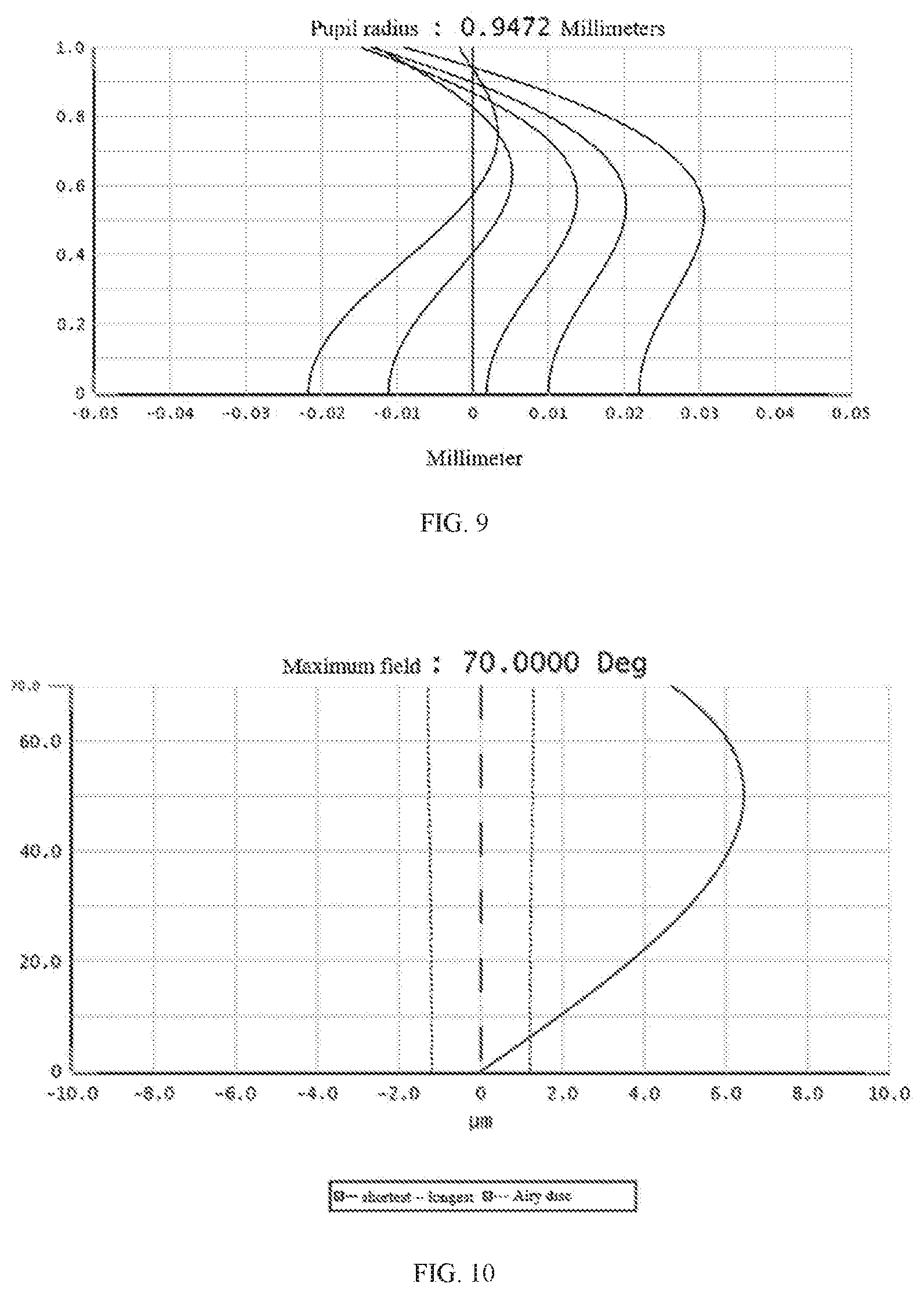
[0031] FIG. 9 is a diagram showing axial spherical aberration curves of the wide-angle lens according to the third embodiment of the disclosure;
[0032] FIG. 10 is a diagram showing lateral chromatic aberration curves of the wide-angle lens according to the third embodiment of the disclosure;
[0033] FIG. 11 is a schematic structural diagram showing a cross-section of a camera module according to a fourth embodiment of the disclosure:
[0034] FIG. 12 is a schematic block diagram of a vehicle camera according to a fifth embodiment of the disclosure;
[0035] FIG. 13 is a schematic diagram of the vehicle camera according to the fifth embodiment of the disclosure.
MAIN REFERENCE NUMERALS
TABLE-US-00001 [0036] Wide-angle lens 100 First lens group Q1 First lens L1 Second lens L2 Third lens L3 Second lens group Q2 Fourth lens L4 Fifth glass L5 Sixth lens L6 Stop ST Filter G Flat glass P1 Imaging plane P2 Cemented doublet Q3
DETAILED DESCRIPTION OF PREFERRED EMBODIMENTS
[0037] Hereinafter, embodiments of the disclosure will be described in detail. Examples of the embodiments are illustrated in the drawings, wherein the same or similar reference numerals represent the same or similar elements or elements having the same or similar functions. The embodiments described below with reference to the drawings are exemplary and are only used to explain the disclosure, but should not be construed to limit the disclosure.
[0038] At present, with the development of autonomous driving, the requirements for vehicle lenses are becoming higher and higher, the requirements include high light transmission ability, high imaging clarity, and good thermal stability. However, most conventional vehicle lenses are sensitive to temperature, not suitable for high or low temperature occasions. In addition, it is difficult to ensure the stability of long-term use of plastic material, because plastic material is greatly affected by temperature and has a short service life; meanwhile, it has low resolution and difficult to eliminate chromatic aberration, which is not conducive to practical application.
[0039] In order to solve the above problems, after research, the inventors propose a wide-angle lens, an imaging device, a camera module, and a vehicle camera of the embodiments of the disclosure, which have the advantages of high imaging quality and good thermal reliability.
[0040] In order to enable those skilled in the art to better understand the solutions of the disclosure, the technical solutions in the embodiments of the disclosure will be clearly and completely described below with reference to the accompanying drawings in the embodiments of the disclosure. Obviously, the described embodiments are only some embodiments but not all embodiments of the disclosure. Based on the embodiments of the disclosure, all other embodiments obtained by those skilled in the art without making creative work fall into the protection scope of the disclosure.
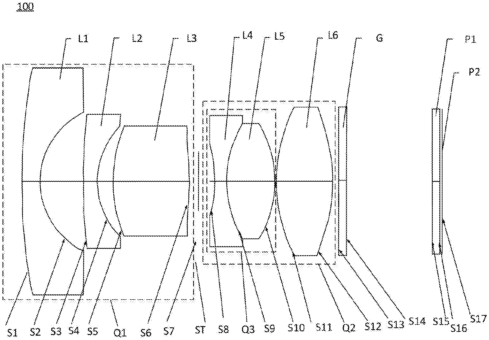
[0041] Please refer to FIG. 1, FIG. 1 is a schematic cross-sectional view of a wide-angle lens 100 according to a first embodiment of the disclosure. From an object side to an image side along an optical axis, the wide-angle lens sequentially includes a first lens group Q1, a second lens group Q2, a stop ST, a filter G, a flat glass P1, and an imaging plane P2.
[0042] The first lens group Q1 has a refractive power, and includes a first lens L1 with a negative refractive power, a second lens L2 with a negative refractive power and a third lens L3 with a positive refractive power from the object side surface to the image side surface. The first lens L1 and the second lens L2 both adopt a meniscus structure. Specifically, as illustrated in FIG. 1, an object side surface S1 of the first lens L1 is convex, an image side surface S2 of the first lens L1 is concave, an object side surface S3 of the second lens L2 is convex, an image side surface S4 of the second lens L2 is concave. An object side surface S5 and an image side surface S6 of the third lens L3 are both convex. That is, the first lens L1 is a meniscus lens, the second lens L2 is a meniscus lens, and the third lens is a bi-convex lens.
[0043] The second lens group Q2 has a positive refractive power, and includes a fourth lens L4 with a negative refractive power, a fifth lens L5 with a positive refractive power and a sixth lens L6 with a positive refractive power. An object side surface S8 and an image side surface S9 of the fourth lens L4 are both concave. An object side surface S9 and an image side surface S10 of the fifth lens L5 are both convex. An object side surface S11 and an image side surface S12 of the sixth lens L6 are both convex. That is, the fourth lens L4 is a bi-concave lens, the fifth lens L5 is a bi-convex lens, and the sixth lens L6 is a bi-convex lens.
[0044] The first lens L1, the second lens L2, the third lens L3, the fourth lens L4, the fifth lens L5 and the sixth lens L6 each are glass lenses, that is, each of the first lens L1, the second lens L2, the third lens L3, the fourth lens IA, the fifth lens L5 and the sixth lens L6 is made of glass material.
[0045] The optical center of every lens is located on the same straight line.
[0046] In addition, the fourth lens L4 and the fifth lens L5 are combined to form a cemented doublet Q3, that is, the cemented doublet Q3 is formed by cementing the fourth lens IA and the fifth lens L5. In this embodiment, the cemented doublet Q3 is mainly configured to improve the luminous flux of the wide-angle lens 100, reduce the difficulty of assembling, and reduce the tolerance sensitivity.
[0047] The stop ST is disposed between the first lens group Q1 and the second lens group Q2.
[0048] The filter G is disposed between the sixth lens L6 and the imaging plane P2. The filter G is configured for selectively filtering some light thereby optimizing the imaging result. A plate glass P1 is disposed between the sixth lens L6 and the imaging plane P2, the plate glass P1 is located behind the filter G. In this embodiment, the imaging plane P2 may be the plane where light incident from the object side and passed through the wide-angle lens 100 imaged on the image side.
[0049] Further, in some embodiments, the wide-angle lens 100 meets the expression:
-10<.phi..sub.2/.phi..sub.1<6,
where .phi..sub.2 represents a refractive power of the second lens L2, .phi..sub.1 represents a refractive power of the first lens group Q1. Satisfying this expression can effectively correct the f-.theta. distortion of the wide-angle lens 100.
[0050] Further, in some embodiments, the wide-angle lens 100 meets the expression:
-15.times.10.sup.-6/.degree. C.<(dN/dT).sub.2+(dN/dT).sub.6<2.times.10.sup.-6/.degree. C.
[0051] where (dN/dT).sub.2 represents a temperature coefficient of refractive index of the second lens L2, (dN/dT).sub.6 represents a temperature coefficient of refractive index of the sixth lens L6. Satisfying this expression can effectively compensate for the effect of temperature changes on the focal length of the wide-angle lens 100, and improve the stability of the resolution of the wide-angle lens 100 under different temperatures.
[0052] Further, in some embodiments, the wide-angle lens 100 meets the expression:
0.3<.phi..sub..PI..phi.<0.8,
[0053] where .phi..sub..PI. represents a refractive power of the second lens group Q2, .phi. represents a refractive power of the wide-angle lens 100. By satisfying this expression, the astigmatism of the wide-angle lens 100 can be effectively corrected, and the resolution of the wide-angle lens 100 can be improved.
[0054] Further, in some embodiments, the wide-angle lens 100 meets the expression:
-0.1<.phi..sub.2/r.sub.21<0,
[0055] where .phi..sub.2 represents a refractive power of the second lens L2, r.sub.21 represents a radius of curvature of the object side surface S3 of the second lens L2. By satisfying this expression, the sensitivity of the lens performance caused by the curvature radius change of the second lens L2, can be reduced; it facilitates the production and processing of lens components and improves the assembly yield.
[0056] Further, in some embodiments, the wide-angle lens 100 meets the expression:
0.ltoreq.(|.DELTA.IH/.DELTA..theta.|.sub.max-|.DELTA.IH/.DELTA..theta.|.- sub.min)/(f*tan(.DELTA..theta.)).ltoreq.0.25,
where .DELTA.IH represents a change of image height of the wide-angle lens 100, .DELTA..theta. represents a change of half-FOV of the wide-angle lens 100, |.DELTA.IH/.DELTA..theta.|.sub.max represents the maximum angular resolution, |.DELTA.IH/.DELTA..theta.|.sub.min, represents the minimum angular resolution, f represent an effective focal length of the wide-angle lens 100. This expression reflects the consistency of the ratio of the change in the image height to the change in the half-FOV, which facilitates to perform digital distortion correction on the formed image.
[0057] In this embodiment, as an implementation manner, the first lens L1, the second lens L2, the third lens L3, the fourth lens L4, the fifth lens L5 and the sixth lens L6 are all spherical lenses. In another embodiment, the sixth lens L6 may be an aspherical lens while the other lenses L1-L5 are spherical lenses. It can be understood that, in other possible implementation manners, the first lens L1, the second lens L2, the third lens L3, the fourth lens L4, the fifth lens L5, and the sixth lens L6 may also be other combination of spherical lenses and aspherical lenses.
[0058] In the application, surface shapes of aspherical lenses meet the following expression:
z = ch 2 1 + 1 - ( 1 + K ) c 2 h 2 + Bh 4 + Ch 6 + Dh 8 + Eh 10 + Fh 12 , ##EQU00001##
[0059] where z represents a vector height between a point on a curved surface and a vertex of the curved surface along an optical axis, c represents a curvature of the vertex of the curved surface, K represents a quadratic surface coefficient, h represents a distance between the point on the curved surface and the optical axis, B represents a fourth order surface coefficient, C represents a sixth order surface coefficient, D represents an eighth order surface coefficient, E represents a tenth order surface coefficient, F represents a twelfth order surface coefficient.
[0060] Further, in some embodiments, an F number of the wide-angle lens 100 is not greater than 1.8, which can meet the imaging requirements in a relatively dark environment. Further, in some embodiments, the FOV of the wide-angle lens 100 is between 80.degree. and 140.degree., that is, the FOV of the wide-angle lens 100 can reach more than 1300, the f-.theta. distortion can be effectively corrected and controlled less than 5%, which facilitates to perform digital distortion correction on the formed image.
[0061] Further, a total optical length is between 20 mm-23 mm.
[0062] Further, in some embodiments, the wide-angle lens 100 meets the expression:
d.sub.12>d.sub.23>d.sub.56; [0063] where d.sub.12 represents a distance between the first lens and the second lens on the optical axis, d.sub.23 represents a distance between the second lens and the third lens on the optical axis, d.sub.56 represents a distance between the fifth lens and the sixth lens on the optical axis.
[0064] Further, in some embodiments, the wide-angle lens 100 meets the expression:
D.sub.1>D.sub.2>D.sub.3;
D.sub.6>D.sub.5;
[0065] where D.sub.1 represents the maximum diameter of the first lens, D.sub.2 represents the maximum diameter of the second lens, D.sub.3 represents the maximum diameter of the third lens, D.sub.5 represents the maximum diameter of the fifth lens, D.sub.6 represents the maximum diameter of the sixth lens.
[0066] In the wide-angle lens 100 provided by the embodiment, the first lens, the second lens, the third lens, the fourth lens, the fifth lens, and the sixth lens are all glass lenses, due to the stable performance of the glass lenses, it can achieve the athermalization over a wide temperature range. The wide-angle lens 100 provided by the embodiment can clearly image in a temperature range of -40.degree. C. to +85.degree. C., and is particularly suitable for the camera fields with relatively harsh environments, such as sports cameras and vehicle cameras. In addition, the wide-angle lens 100 may include one or more aspherical lenses, the use of the aspherical lens can effectively correct aberrations of the wide-angle lens 100 and improve the resolution of the entire group of the wide-angle lens 100.
[0067] Further, the disclosure further provides an imaging device, which includes the wide-angle lens 100 provided in any one of the foregoing embodiments and an imaging element for converting an optical image formed by the wide-angle lens 100 into electrical signals. The imaging element may be a complementary metal oxide semiconductor (CMOS) image sensor or a charge coupled device (CCD) image sensor. The imaging device may be a device such as a vehicle-mounted device, a monitoring device, and the like, and it has the beneficial effects brought by the wide-angle lens 100 provided by the disclosure.
Embodiment 1
[0068] Please refer to FIG. 1, it is a schematic cross-sectional view of a wide-angle lens 100 according to a first embodiment of the disclosure. The sixth lens L6 is a glass spherical lens. Relevant parameters of every lens of the wide-angle lens 100 are shown in Table 1.
TABLE-US-00002 TABLE 1 Radius Abbe Surface Surface of Thick- Refrac- num- No. type curvature ness tivity ber Object -- Infinity First lens S1 Spherical 9.111 1.20 1.804 46.6 L1 surface S2 Spherical 3.413 3.65 surface Second lens S3 Spherical 89.542 1.50 1.497 81.6 L2 surface S4 Spherical 3.416 0.83 surface Third lens S5 Spherical 5.523 2.68 1.923 18.9 L3 surface S6 Spherical -32.323 0.14 surface Stop ST S7 -- 0.31 Fourth lens S8 Spherical -19.947 0.65 1.946 17.9 L4 surface Fifth lens S9 Spherical 4.495 2.20 1.62 17.9 L5 surface S10 Spherical -4.889 0.096 surface Sixth lens S11 Spherical 11.567 3.12 1.768 49.2 L6 surface S12 Spherical -16.978 0.30 surface Filter G S13 -- 0.400 1.517 64.21 S14 -- 5.30 Plate glass S15 -- 0.50 1.517 64.21 P1 S16 -- 0.125 Imaging S17 -- -- plane P2
[0069] In this embodiment, the curves of the field curvature, the axial spherical aberration and the lateral chromatic aberration are shown in FIG. 2, FIG. 3, and FIG. 4, respectively. From FIG. 2 to FIG. 4, it is apparent that the field curvature, the axial spherical aberration and the lateral chromatic aberration can be well corrected.
Embodiment 2
[0070] A wide-angle lens 100 of this embodiment is substantially similar to the wide-angle lens 100 of the first embodiment. The main differences are the design parameters, and another difference is that: a first lens L1, a second lens L2, a third lenses L3, a fourth lens L4 and a fifth lens L5 of this are all spherical lenses, while a sixth lens L6 of this embodiment is an aspheric lens. Relevant parameters of every lens of the wide-angle lens 100 are shown in Table 2-1 and 2-2.
TABLE-US-00003 TABLE 2-1 Radius Abbe Surface Surface of Thick- Refrac- num- No. type curvature ness tivity ber Object -- Infinity First lens S1 Spherical 15.888 1.20 1.569 56.0 L1 surface S2 Spherical 3.611 2.61 surface Second lens S3 Spherical 1243.35 0.80 1.497 81.6 L2 surface S4 Spherical 4.165 0.64 surface Third lens S5 Spherical 7.122 3.16 2.001 25.4 L3 surface S6 Spherical -21.368 0.15 surface Stop ST S7 -- 0.67 Fourth lens S8 Spherical -7.175 0.65 1.847 23.8 L4 surface Fifth lens S9 Spherical 5.476 2.55 1.755 52.3 L5 surface S10 Spherical -5.666 0.10 surface Sixth lens S11 Aspherical 6.776 3.37 1.497 81.6 L6 surface S12 Aspherical -8.612 0.30 surface Filter G S13 -- 0.40 1.517 64.21 S14 -- 4.285 Plate glass S15 -- 0.40 1.517 64.21 P1 S16 -- 0.125 Imaging S17 -- -- plane P2
[0071] In this embodiment, aspherical parameters of every lens of the optical imaging lens 100 are shown in Table 2-2.
TABLE-US-00004 TABLE 2-2 Surface No. K B C D E F S11 -0.332 -5.556e-4 7.015e-5 -3.241e-6 1.517e-7 1.054e-10 S12 -1.325 1.050e-3 -6.860e-5 1.659e-5 -1.224e-6 4.111e-8
[0072] In this embodiment, the curves of the field curvature, the axial spherical aberration and the lateral chromatic aberration are shown in FIG. 5, FIG. 6, and FIG. 7, respectively. From FIG. 5 to FIG. 7, it is apparent that the field curvature, the axial spherical aberration and the lateral chromatic aberration can be well corrected.
[0073] In this embodiment, a hybrid structure of five glass spherical lenses and one glass aspherical lens can realize clear imaging in a temperature range of -40.degree. C. to +85.degree. C., improve ghost images generated on an optical element surface near the imaging plane, and meet the requirements of wide-angle performance and high imaging quality.
Embodiment 3
[0074] A wide-angle lens 100 of this embodiment is substantially similar to the wide-angle lens 100 of the first embodiment, and the difference is that: a sixth lens L6 of this embodiment is a glass aspheric lens. The design parameters of the wide-angle lens of this embodiment are different from that of the second embodiment. Relevant parameters of every lens in the wide-angle lens 100 are shown in Tables 3-1 to 3-2.
TABLE-US-00005 TABLE 3-1 Radius Abbe Surface Surface of Thick- Refrac- num- No. type curvature ness tivity ber Object -- Infinity First lens S1 Spherical 27.223 1.20 1.49 70.4 L1 surface S2 Spherical 3.594 2.19 surface Second lens S3 Spherical 25.645 0.80 1.49 70.4 L2 surface S4 Spherical 3.915 0.70 surface Third lens S5 Spherical 7.539 2.52 1.92 20.9 L3 surface S6 Spherical -27.943 0.26 surface Stop ST S7 -- 0.51 Fourth lens S8 Spherical -6.233 0.65 1.85 23.8 L4 surface Fifth lens S9 Spherical 5.897 2.46 1.73 54.6 L5 surface S10 Spherical -5.284 0.10 surface Sixth lens S11 Aspherical 7.516 3.65 1.50 81.6 L6 surface S12 Aspherical -5.758 0.3 surface Filter G S13 -- 0.40 1.517 64.21 S14 -- 4.78 Plate glass S15 -- 0.40 1.517 64.21 P1 S16 -- 0.125 Imaging S17 -- -- plane P2
[0075] In this embodiment, aspherical parameters of every lens of the optical imaging lens 100 are shown in Table 3-2.
TABLE-US-00006 TABLE 3-2 Surface No. K B C D E F S11 -5.495 4.095e-4 5.437e-6 -1.092e-6 5.787e-8 -3.022e-11 S12 -0.995 4.600e-4 -2.163e-5 2.756e-6 -1.562e-7 4.614e-9
[0076] In this embodiment, the curves of the field curvature, the axial spherical aberration and the lateral chromatic aberration are shown in FIG. 8, FIG. 9, and FIG. 10, respectively. From FIG. 8 to FIG. 10, it is apparent that the field curvature, the axial spherical aberration and the lateral chromatic aberration can be well corrected.
[0077] Table 4 shows the corresponding optical characteristics of the optical imaging lens 100 in the above three embodiments, including the focal length f, the F number F #, the field of view 20, the total optical length T.sub.L, and related values corresponding to the aforementioned expressions.
TABLE-US-00007 TABLE 4 Embodi- Embodi- Embodi- expression ment 1 ment 2 ment 3 f (mm) 3.387 3.462 3.41 F# 1.8 1.8 1.8 2.theta. 130.degree. 134.degree. 140.degree. T.sub.L (mm) 22.93 21.4 21 .phi..sub.2/.phi..sub.I -9.31 -8.43 5.23 (dN/dT).sub.2 + (dN/dT).sub.6 0.4 .times. -12.1 .times. -7.3 .times. 10.sup.-6/.degree. C. 2.0.sup.-6/.degree. C. 10.sup.-6/.degree. C. .phi..sub.II/.phi. 0.511 0.609 0.649 .phi..sub.2/r.sub.21 -0.049 -0.005 -0.350 |.DELTA.IH/.DELTA..theta.|.sub.max 0.0593 0.0604 0.0595 |.DELTA.IH/.DELTA..theta.|.sub.min 0.0591 0.0580 0.0458 (|.DELTA.IH/.DELTA..theta.|.sub.max - 0.0338 0.0397 0.2328 |.DELTA.IH/.DELTA..theta.|.sub.min)/(f*tan(.DELTA..theta.))
[0078] According to Table 4, the total optical length of the wide-angle lens 100 is less than 23 mm, the F number F # is 1.8, and the FOV 2.theta. is 130.degree..about.140.degree..
[0079] The wide-angle lens 100 of the present application has a small volume, the sixth lens L6 is designed to be a glass aspheric lens, which effectively reduces the aberration and improves the imaging quality of the wide-angel lens 100. By appropriately matching the temperature coefficient of refractive index of the second lens L2 and the sixth lens L6, the problem of focus shift caused by refractive index changes with temperature is solved, so that the wide-angle lens 100 has good imaging effects in various temperature occasions, and the practicability of the wide-angle lens 100 is improved.
Embodiment 4
[0080] FIG. 11 illustrates a camera module 200, which includes the wide-angle lens 100 of any embodiment as described above, a barrel 201, a holder 202, an image sensor 203, and a printed circuit board 204. The wide-angle lens 100 is received in the barrel 201, and the barrel 201 is engaged with the holder 202. The image sensor 203 and the printed circuit board 204 are substantially accommodated in the holder 202. The image sensor 203 is opposite to the wide-angle lens 100 and is mounted on the printed circuit board 204. The image sensor 203 is configured for converting light signals into electrical signals, thereby the images formed by the wide-angle lens 100 can be converted and transmitted to a processor. The printed circuit board 204 can be further electrically connected to a chip or the processor via a flexible circuit board.
Embodiment 5
[0081] FIGS. 12 and 13 illustrates a vehicle camera 300, which includes the camera module 200 as described above, a processor 301, and a memory 302. The camera module 200 is configured to capture images of the surroundings, the processor 301 is configured to process the captured images, and the memory 302 is configured to store the captured images. The processor 301 is communicated with the camera module 200 and the memory 302. That is, the captured images can be transmitted to the processor 301 and stored in the memory 302. The vehicle camera 300 is installed in a car 400, and can be applied to an automatic driving system of the car 400, so that the driverless vehicle system can control the direction and the speed of the car 400 according to the captured images of the surroundings.
[0082] The above embodiments just describe some implementation manners of the disclosure, the descriptions are specific and detailed, but cannot be understood as limiting the scope of the application. It should be noted that, for those of ordinary skill in the art, without departing from the concept of the application, modifications and improvements can be made, which should belong to the protection scope of the application. Therefore, the protection scope of this application should be subject to the appended claims.
* * * * *
D00000
D00001
D00002
D00003
D00004
D00005
D00006
P00999
XML
uspto.report is an independent third-party trademark research tool that is not affiliated, endorsed, or sponsored by the United States Patent and Trademark Office (USPTO) or any other governmental organization. The information provided by uspto.report is based on publicly available data at the time of writing and is intended for informational purposes only.
While we strive to provide accurate and up-to-date information, we do not guarantee the accuracy, completeness, reliability, or suitability of the information displayed on this site. The use of this site is at your own risk. Any reliance you place on such information is therefore strictly at your own risk.
All official trademark data, including owner information, should be verified by visiting the official USPTO website at www.uspto.gov. This site is not intended to replace professional legal advice and should not be used as a substitute for consulting with a legal professional who is knowledgeable about trademark law.