Implantable Fasteners, Applicators, And Methods For Brachytherapy
Kind Code
U.S. patent application number 16/861700 was filed with the patent office on 2020-08-13 for implantable fasteners, applicators, and methods for brachytherapy. The applicant listed for this patent is Covidien LP. Invention is credited to Thomas Campanelli, Matthew Chowaniec, Gerald Hodgkinson, Stanislaw Kostrzewski, David Nicholas, Lee A. Olson, Robert Pedros, Russell Pribanic.
| Application Number | 20200254276 16/861700 |
| Document ID | 20200254276 / US20200254276 |
| Family ID | 1000004786667 |
| Filed Date | 2020-08-13 |
| Patent Application | download [pdf] |
View All Diagrams
| United States Patent Application | 20200254276 |
| Kind Code | A1 |
| Kostrzewski; Stanislaw ; et al. | August 13, 2020 |
IMPLANTABLE FASTENERS, APPLICATORS, AND METHODS FOR BRACHYTHERAPY
Abstract
A fastener applicator includes a body portion including a handle assembly, a cartridge assembly supported within the body portion, the cartridge assembly including implantable fasteners, a drive assembly supported within the body portion and operatively coupled to the cartridge assembly to engage the implantable fasteners, and an actuation assembly supported within the handle assembly and operatively coupled to the drive assembly to fire a distal-most implantable fastener upon actuation of the actuation assembly. At least one of the implantable fasteners includes a body including a tissue facing surface, a tissue penetrating portion extending from the body, and a capsule affixed to the tissue facing surface of the body, the capsule including radioactive material.
| Inventors: | Kostrzewski; Stanislaw; (Newton, CT) ; Hodgkinson; Gerald; (Killingworth, CT) ; Olson; Lee A.; (Wallingford, CT) ; Pribanic; Russell; (Roxbury, CT) ; Chowaniec; Matthew; (Madison, CT) ; Pedros; Robert; (Oxford, CT) ; Campanelli; Thomas; (Oxford, CT) ; Nicholas; David; (Trumbull, CT) | ||||||||||
| Applicant: |
|
||||||||||
|---|---|---|---|---|---|---|---|---|---|---|---|
| Family ID: | 1000004786667 | ||||||||||
| Appl. No.: | 16/861700 | ||||||||||
| Filed: | April 29, 2020 |
Related U.S. Patent Documents
| Application Number | Filing Date | Patent Number | ||
|---|---|---|---|---|
| 15835853 | Dec 8, 2017 | |||
| 16861700 | ||||
| 62514089 | Jun 2, 2017 | |||
| 62451936 | Jan 30, 2017 | |||
| 62442610 | Jan 5, 2017 | |||
| Current U.S. Class: | 1/1 |
| Current CPC Class: | A61N 5/1001 20130101; A61N 5/1015 20130101; A61B 2017/0649 20130101; A61M 39/0208 20130101; A61B 17/068 20130101; A61N 2005/101 20130101; A61N 2005/1024 20130101; A61N 5/1007 20130101; A61B 17/0644 20130101; A61B 17/0684 20130101; A61B 2017/00004 20130101; A61B 2090/3966 20160201; A61N 5/1027 20130101 |
| International Class: | A61N 5/10 20060101 A61N005/10; A61B 17/068 20060101 A61B017/068; A61B 17/064 20060101 A61B017/064 |
Claims
1. (canceled)
2. An implantable fastener comprising: a body defining a longitudinal axis, the body including first and second ends; a first leg extending from the first end of the body and towards the second end of the body, the first leg including a first tissue penetrating portion; a second leg extending from the second end of the body and towards the first end of the body, the second leg including a second tissue penetrating portion; and a capsule associated with the body, the capsule including a radioactive material.
3. The implantable fastener according to claim 2, wherein the body defines a lumen configured to receive the capsule therein.
4. The implantable fastener according to claim 2, wherein the capsule is secured to the body via a press fit engagement or friction fit engagement.
5. The implantable fastener according to claim 2, wherein the first tissue penetrating portion is disposed adjacent the second end of the body.
6. The implantable fastener according to claim 2, wherein the second tissue penetrating portion is disposed adjacent the first end of the body.
7. The implantable fastener according to claim 2, wherein the body and the first and second legs are formed of titanium, stainless steel, or polymer.
8. The implantable fastener according to claim 2, wherein the body and the first and second legs define an S-shaped profile.
9. An implantable fastener comprising: a coil body including opposing first and second ends, the first end including a tissue penetrating portion, the second end including a tang extending generally inwardly towards the center of the coil body; and at least one capsule associated with the tang, the at least one capsule including a radioactive material.
10. The implantable fastener according to claim 9, wherein the at least one capsule is disposed on an outer surface of the tang.
11. The implantable fastener according to claim 10, wherein the tang includes a flat surface supporting the at least one capsule.
12. The implantable fastener according to claim 10, wherein the at least one capsule is welded to the tang.
13. The implantable fastener according to claim 9, wherein the tang defines a cavity configured to receive at least one capsule therein.
14. The implantable fastener according to claim 13, wherein the tang includes a plug to close the cavity.
15. The implantable fastener according to claim 9, wherein the tissue penetrating portion has a penetrating point.
16. The implantable fastener according to claim 9, wherein the tang includes a crimped portion defining an opening configured to receive the at least one capsule.
17. The implantable fastener according to claim 16, wherein the crimped portion of the tang frictionally secures the at least one capsule thereto.
18. The implantable fastener according to claim 16, wherein the crimped portion of the tang defines a groove supporting the at least one capsule.
19. The implantable fastener according to claim 16, wherein the at least one capsule is orthogonal to the tang.
20. The implantable fastener according to claim 9, wherein the coil body is formed of stainless steel or polymer.
Description
CROSS-REFERENCE TO RELATED APPLICATIONS
[0001] This application is a continuation of U.S. patent application Ser. No. 15/835,853, filed Dec. 8, 2017, which claims the benefit of and priority to U.S. Provisional Patent Application Ser. No. 62/514,089, filed Jun. 2, 2017, U.S. Provisional Patent Application Ser. No. 62/451,936, filed Jan. 30, 2017, and U.S. Provisional Patent Application Ser. No. 62/442,610, filed Jan. 5, 2017, the entire disclosure of each of which is incorporated by reference herein.
BACKGROUND
1. Technical Field
[0002] The present disclosure relates to surgical implants, staples, clips or fasteners and, more particularly, to implantable fasteners including low dose brachytherapy capsules, and fastener applicators therefor.
2. Background of Related Art
[0003] Generally, brachytherapy is an advanced form of cancer treatment. Specifically, radioactive seeds (alone or incorporated within sutures, buttresses or the like) are placed in or near the cancer site itself, where they emit a relatively low dose of radiation directly to the cancer site while reducing exposure of surrounding healthy tissue to the radiation.
[0004] Depending on the underlying cancer to be treated and on the underlying tissue, particular dosimetry guidelines have been developed for the placement of radioactive seeds and for the radiation levels emitted by the radioactive seeds. Generally, the radioactive seeds are placed at predefined distances relative to one another in order to enable effective dosimetry.
[0005] Accordingly, improved structures incorporating radioactive seeds and methods of placing those structures at or near cancer sites may be advantageous.
SUMMARY
[0006] Implantable fasteners having brachytherapy capsules including radioactive seeds are provided in accordance with the present disclosure. The implantable fasteners having brachytherapy capsules are individually placed at a cancer site using fastener applicators in accordance with the present disclosure.
[0007] According to an aspect of the present disclosure, a fastener applicator is provided and includes a body portion including a handle assembly, a cartridge assembly supported within the body portion, the cartridge assembly including implantable fasteners, a drive assembly supported within the body portion and operatively coupled to the cartridge assembly to engage the implantable fasteners, and an actuation assembly supported within the handle assembly and operatively coupled to the drive assembly to fire a distal-most implantable fastener upon actuation of the actuation assembly. At least one of the implantable fasteners includes a body including a tissue facing surface, a tissue penetrating portion extending from the body, and a capsule affixed to the tissue facing surface of the body, the capsule including radioactive material.
[0008] In certain embodiments, at least one of the implantable fasteners may be a surgical staple and include a radioactive material configured to provide a dose of radiation to a target surgical site.
[0009] In some embodiments, the body of at least one of the implantable fasteners includes a backspan having the tissue facing surface, the tissue facing surface defining a flattened surface extending along at least a portion thereof, the flattened surface providing an increased surface area for affixing the capsule onto the tissue facing surface of the backspan.
[0010] In embodiments, the tissue penetrating portion of at least one of the implantable fasteners includes a first leg extending from a first end portion of the backspan and a second leg extending from a second end portion of the backspan, wherein the first leg and the second leg extend substantially in a same direction from the backspan.
[0011] In certain embodiments, the tissue penetrating portion of at least one of the implantable fasteners includes an unformed condition wherein the first leg and the second leg are substantially parallel to one another and spaced a relative distance from one another, and a formed condition wherein the first leg and the second leg are radiused and in relative close approximation to one another and the backspan.
[0012] In some embodiments, radioactive material is dispersed throughout at least one of the implantable fasteners such that the entirety of at least one of the implantable fasteners emits radiation.
[0013] In embodiments, the implantable fasteners includes a first implantable fastener having sufficient mechanical strength to hold tissue together, and a second implantable fastener having the capsule affixed thereon for providing the dose of radiation to the target surgical site.
[0014] In certain embodiments, each of the first leg and the second leg of the surgical staple includes a first portion and a second portion, the first portion of the first leg and the first portion of the second leg extending away from the backspan at an angle such that the first portions of the first leg and the second leg overlap, the second portions of the first leg and the second leg extending from the first portions of each of the first leg and the second leg, respectively, towards the backspan.
[0015] According to another aspect of the present disclosure, a method of performing a surgical procedure at a surgical site includes positioning a fastener applicator within an opening in tissue, the fastener applicator loaded with implantable fasteners, each implantable fastener having a body including a tissue facing surface, a tissue penetrating portion extending from the body, and a capsule affixed to the tissue facing surface of the body, the capsule including radioactive material. The method further includes locating a first target of the surgical site, and firing the fastener applicator to secure a first implantable fastener to the first target of the surgical site such that the capsule affixed thereon is in contact with tissue adjacent the first target of the surgical site.
[0016] In embodiments, the method further includes locating a second target of the surgical site, relocating the fastener applicator to the second target of the surgical site, and firing the fastener applicator to secure a second implantable fastener to the second target such that the capsule affixed thereon is in contact with tissue adjacent the second target of the surgical site.
[0017] In certain embodiments, the method further includes locating a plurality of targets of the surgical site, relocating the fastener applicator to the plurality of targets of the surgical site, and arranging the implantable fasteners in any configuration, in any pattern, or in any quantity.
BRIEF DESCRIPTION OF THE DRAWINGS
[0018] The present disclosure will be further described with reference to the accompanying drawings, wherein like reference numerals refer to like parts in the several views, and wherein:
[0019] FIG. 1A is a perspective view of an implantable fastener in accordance with an embodiment of the present disclosure in an unformed condition;
[0020] FIG. 1B is a perspective view of the implantable fastener of FIG. 1A in a formed condition;
[0021] FIG. 1C is a perspective view of a backspan of the implantable fastener of FIG. 1A, illustrating a tissue facing surface thereof;
[0022] FIGS. 2A and 2B are perspective views of the implantable fastener of FIG. 1A, illustrating a capsule affixed thereon at various locations of the backspan;
[0023] FIG. 3A is a perspective view of an implantable fastener in accordance with another embodiment of the present disclosure in an unformed condition;
[0024] FIG. 3B is a perspective view of the implantable fastener of FIG. 3A in a formed condition;
[0025] FIG. 4A is a perspective view of an implantable fastener in accordance with another embodiment of the present disclosure in an unformed condition;
[0026] FIG. 4B is a perspective view of the implantable fastener of FIG. 4A in a formed condition;
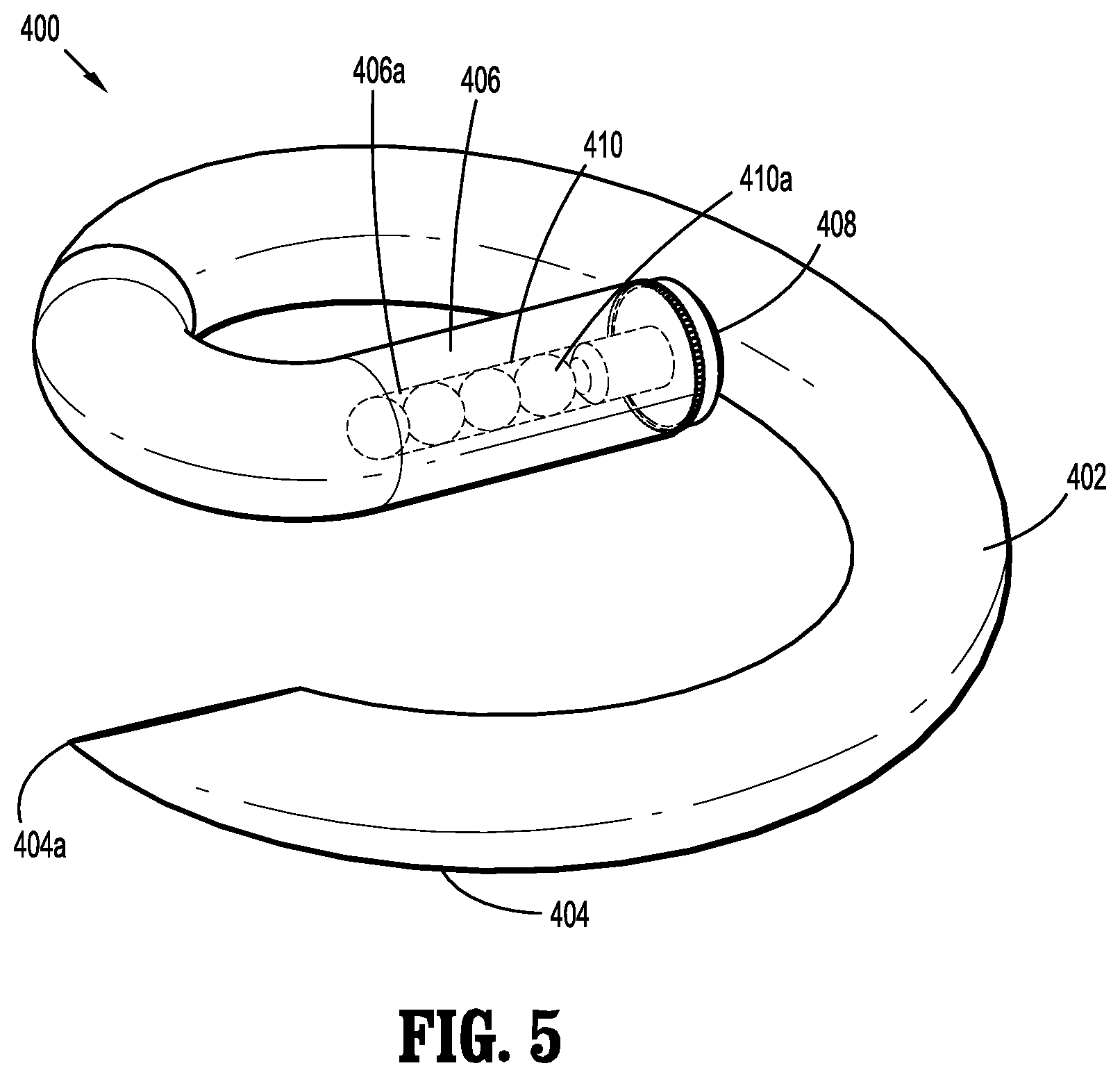
[0027] FIG. 5 is a perspective view of an implantable fastener in accordance with another embodiment of the present disclosure;
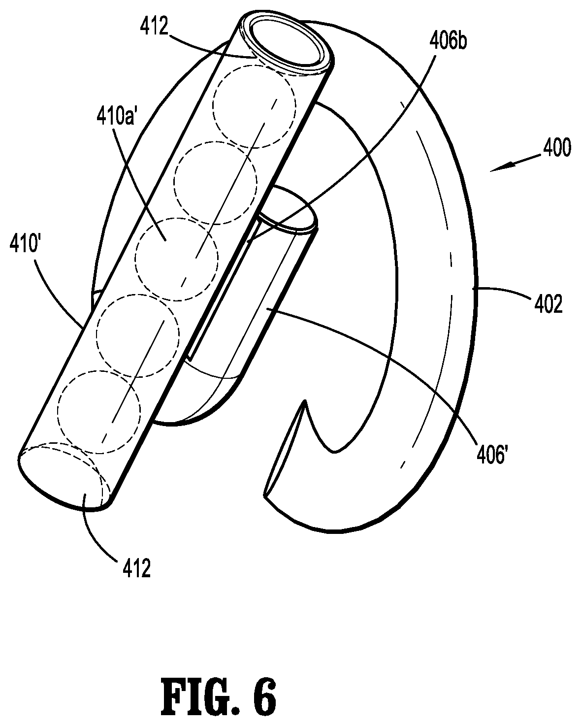
[0028] FIG. 6 is a perspective view of an implantable fastener in accordance with another embodiment of the present disclosure;
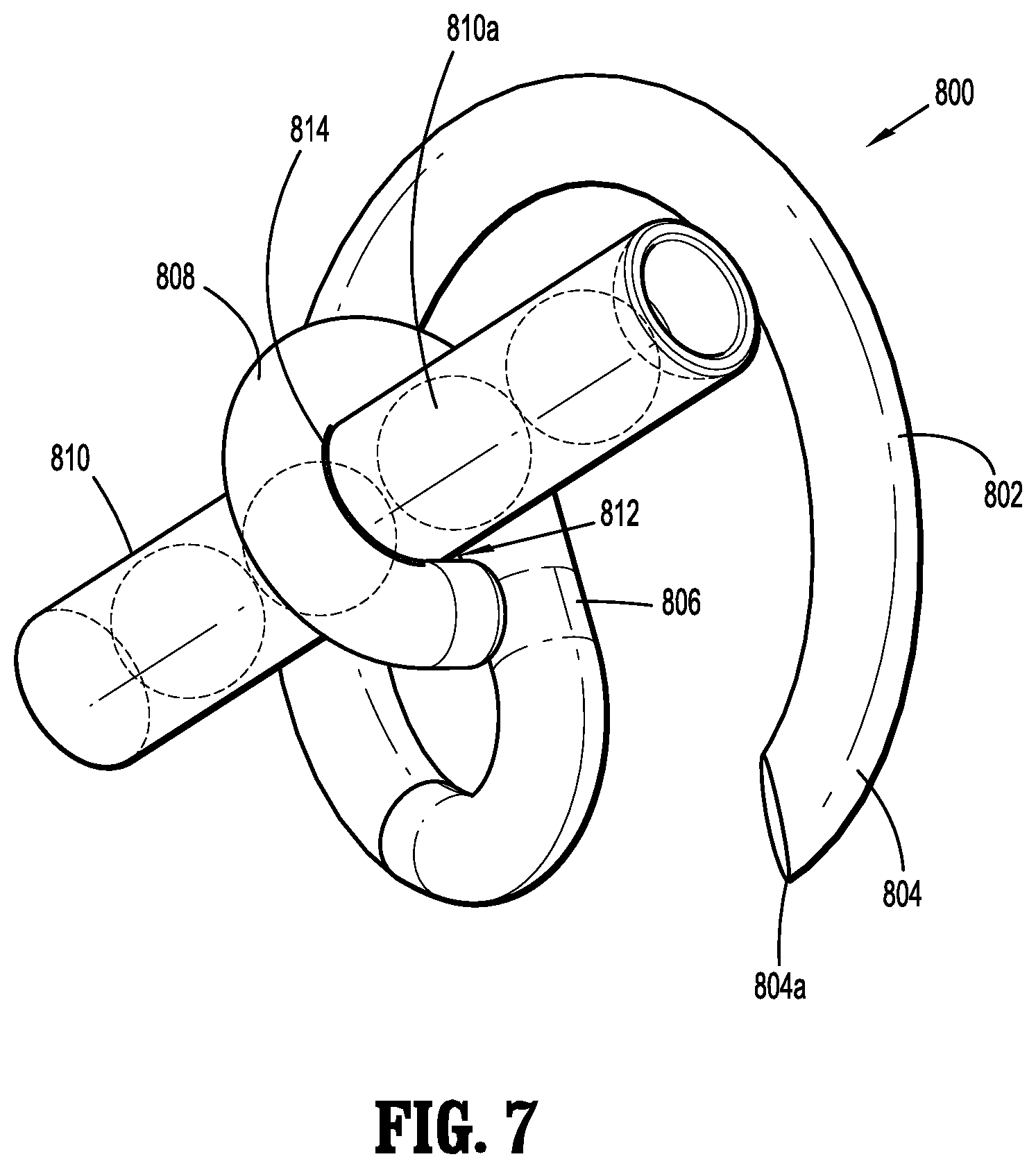
[0029] FIG. 7 is a perspective view of an implantable fastener in accordance with another embodiment of the present disclosure;
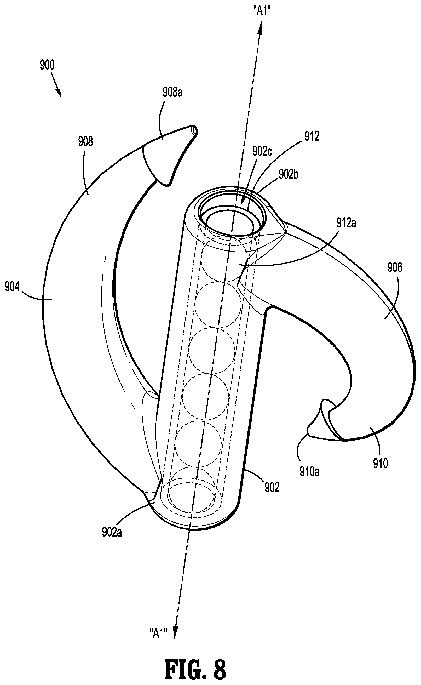
[0030] FIG. 8 is a perspective view of an implantable fastener in accordance with another embodiment of the present disclosure;
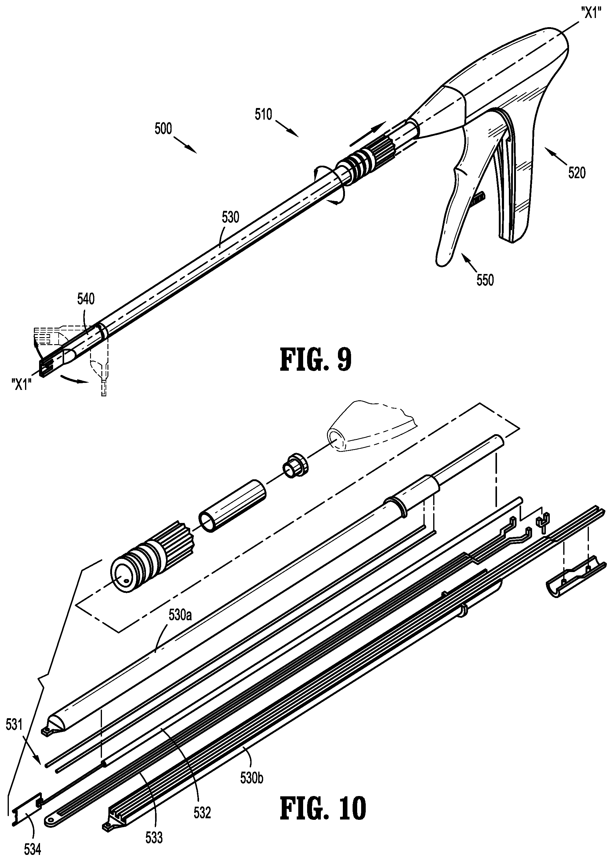
[0031] FIG. 9 is a perspective view of a fastener applicator in accordance with an embodiment of the present disclosure, for applying the implantable fasteners of FIGS. 1A-2B;
[0032] FIG. 10 is an exploded view, with parts separated, of an endoscopic shaft assembly of the fastener applicator of FIG. 9;
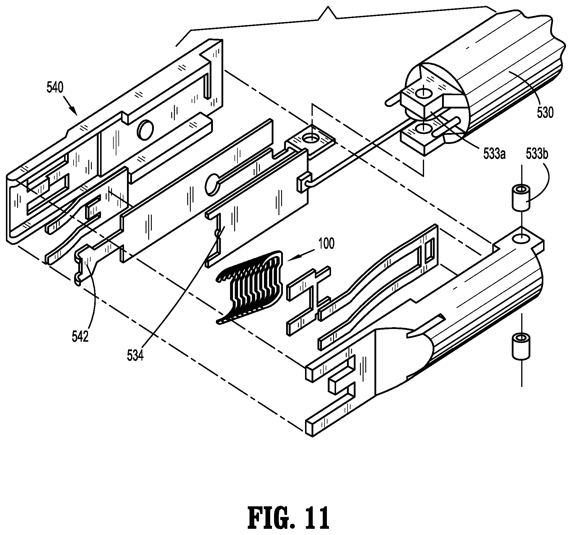
[0033] FIG. 11 is an exploded view, with parts separated, of a cartridge assembly of the fastener applicator of FIG. 9;
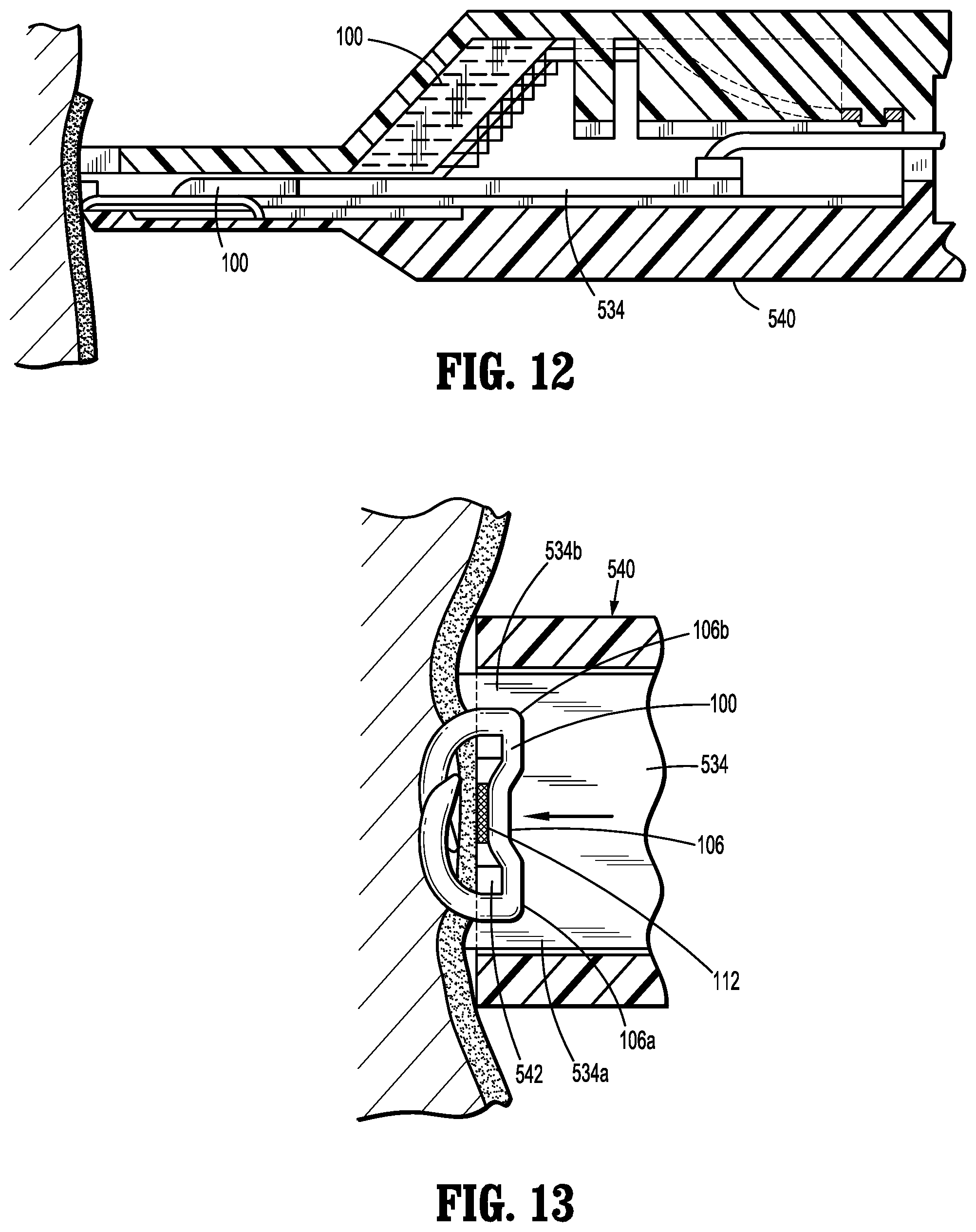
[0034] FIG. 12 is a side cross-sectional view of a distal end portion of the cartridge assembly of FIG. 11 prior to firing the implantable fastener;
[0035] FIG. 13 is a top cross-sectional view of the distal end portion of the cartridge assembly of FIG. 11, illustrating the implantable fastener formed in tissue;
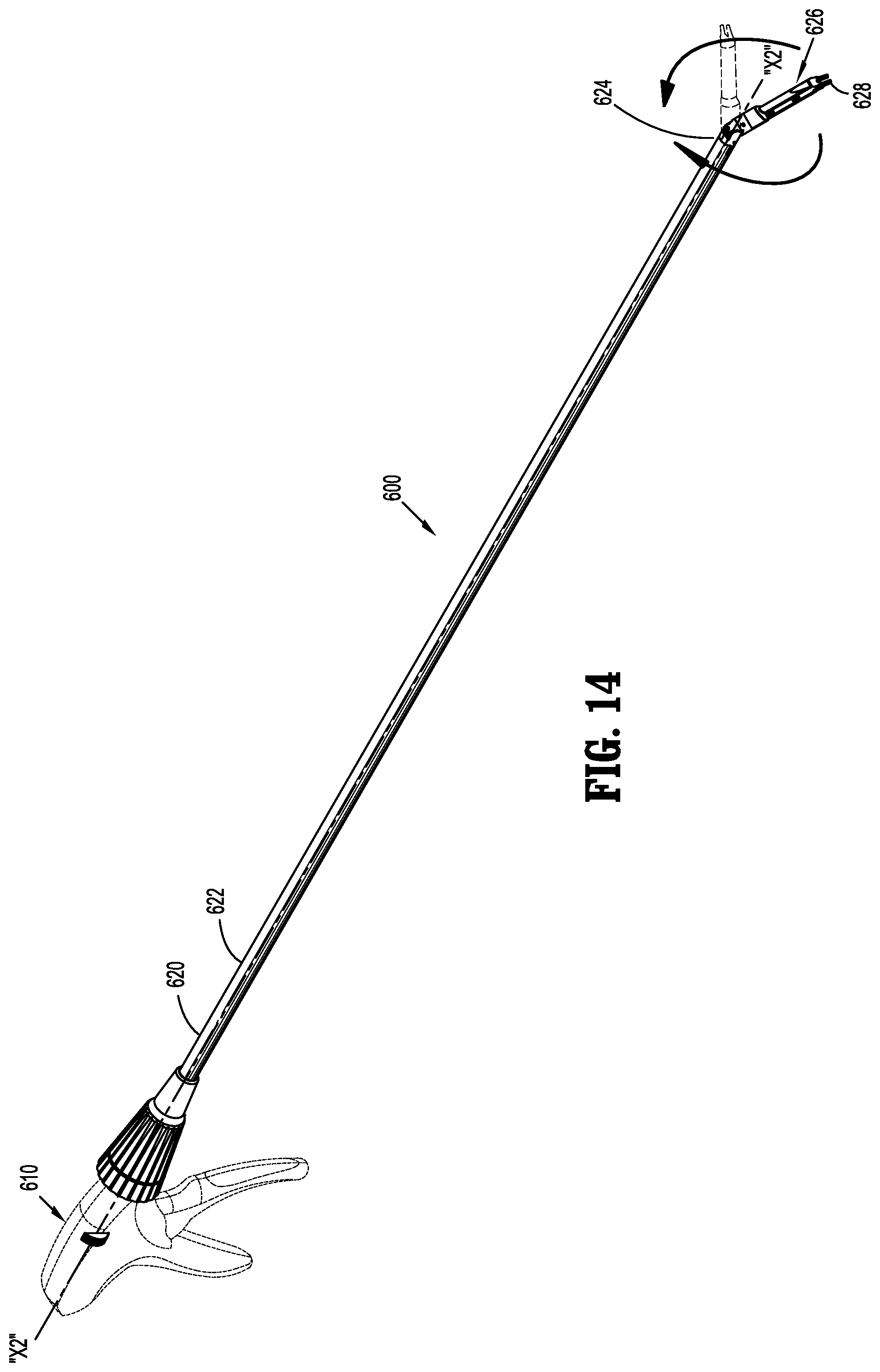
[0036] FIG. 14 is a perspective view of a fastener applicator in accordance with another embodiment of the present disclosure, for applying the implantable fasteners of FIGS. 3A-4B;
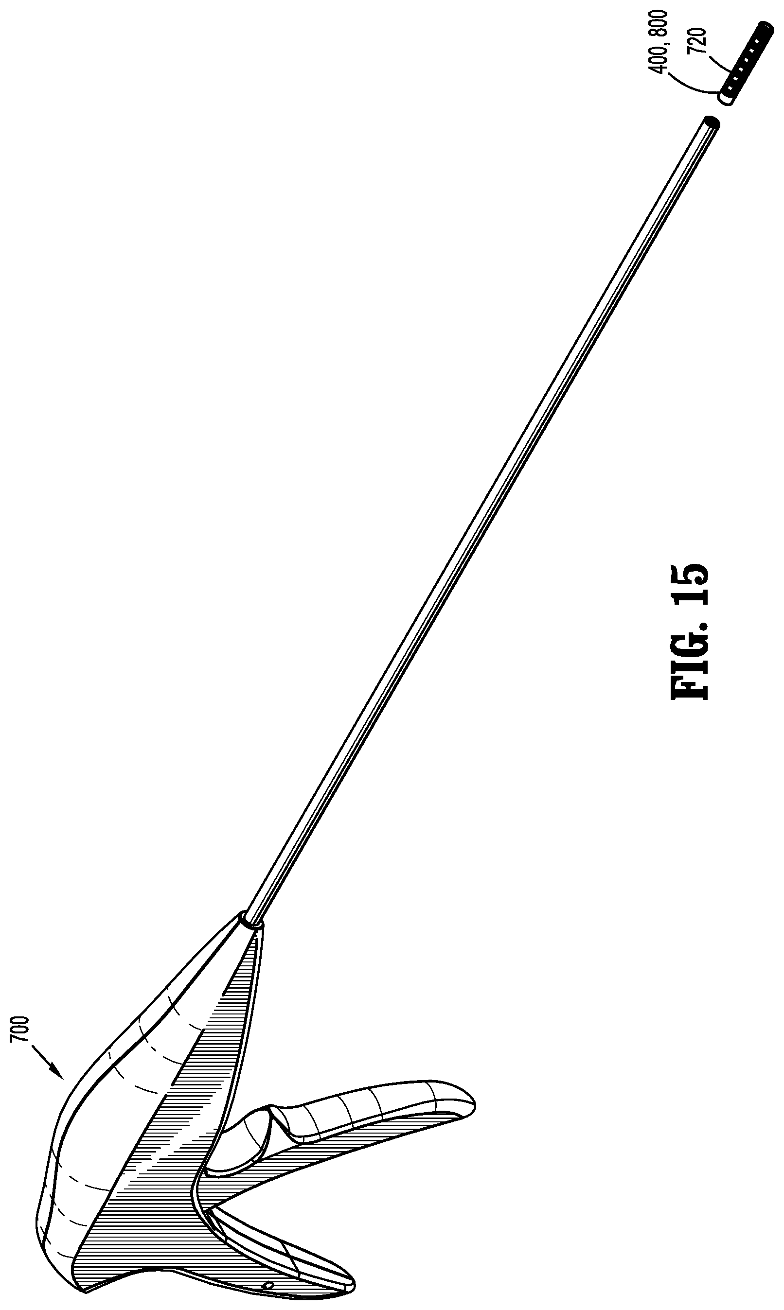
[0037] FIG. 15 is a perspective view of a fastener applicator in accordance with another embodiment of the present disclosure, for applying the implantable fasteners of FIGS. 5-8, including an embodiment of a cartridge assembly for loading the implantable fasteners of FIGS. 5-8; and
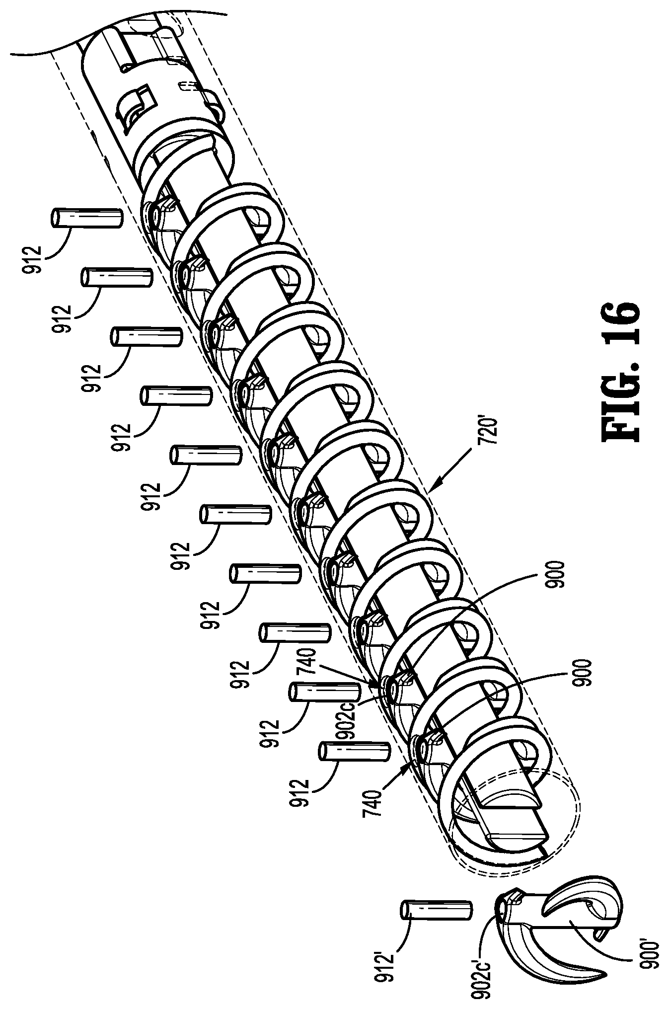
[0038] FIG. 16 is a perspective view of another embodiment of a cartridge assembly of the fastener applicator of FIG. 15 for loading the implantable fastener of FIG. 8.
DETAILED DESCRIPTION OF EMBODIMENTS
[0039] Embodiments of the presently disclosed implantable fasteners and fastener applicators will now be described in detail with reference to the drawings, in which like reference numerals designate identical or corresponding elements in each of the several views. In the drawings and in the description that follows, the term "proximal" will refer to the end of the implantable fasteners and fastener applicator which are closest to the operator, while the term "distal" will refer to the end of the implantable fasteners and fastener applicator which are farthest from the operator.
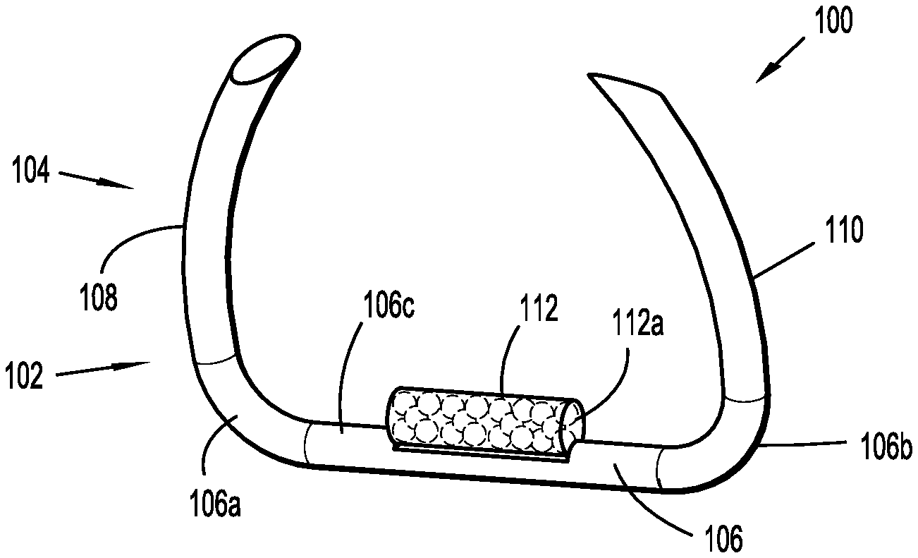
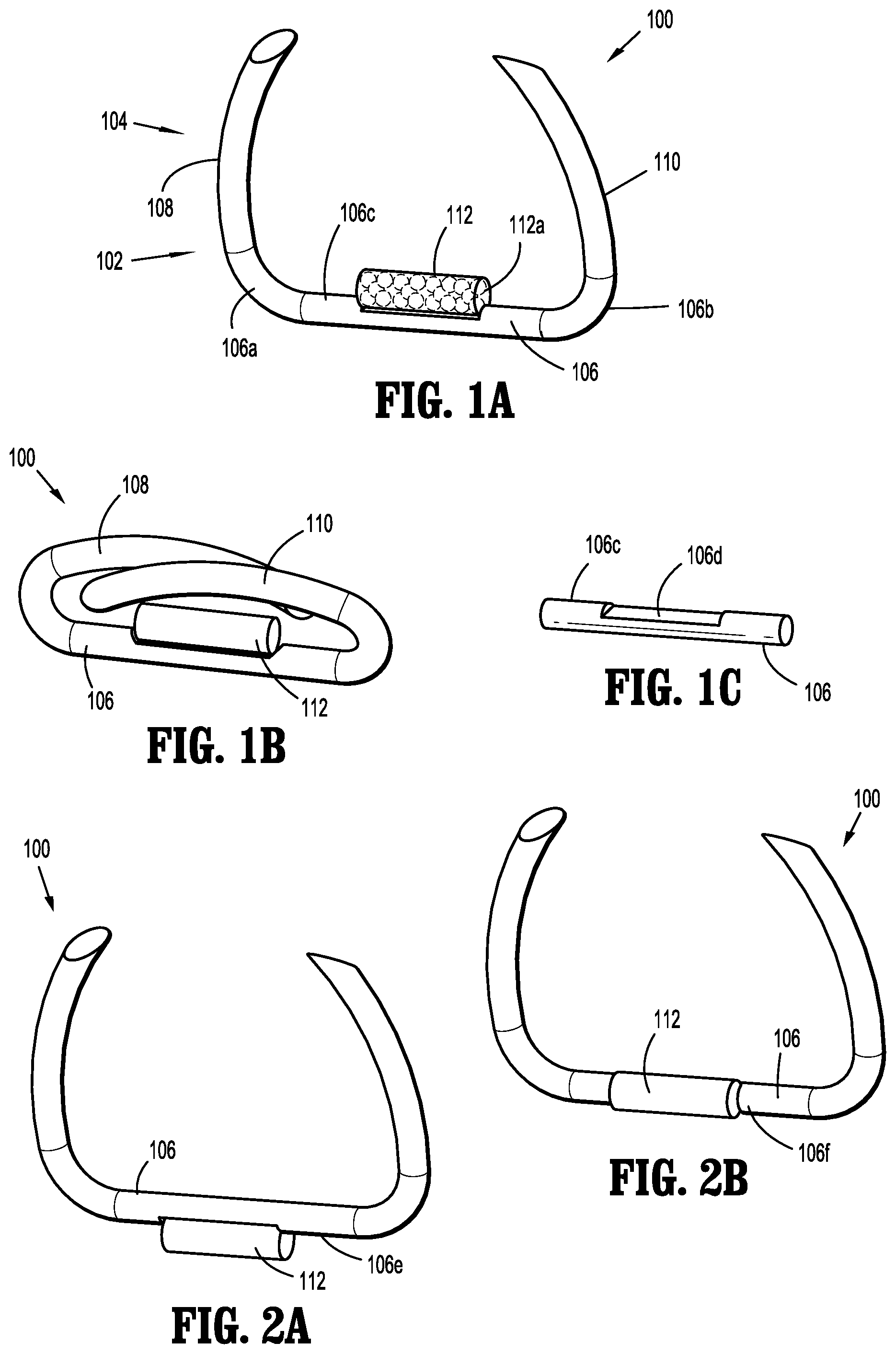
[0040] In accordance with the present disclosure, as illustrated in FIGS. 1A-1C, an embodiment of an implantable fastener 100 is provided and generally includes a body 102 and a tissue penetrating portion 104 extending from the body 102. The body 102 includes a crown or backspan 106 and the tissue penetrating portion 104 includes a first leg 108 extending from a first end portion 106a of the backspan 106 and a second leg 110 extending from a second end portion 106b of the backspan 106. The first leg 108 and the second leg 110 may extend in a same direction such as, for example, distally from the backspan 106.
[0041] The backspan 106 includes a top or tissue facing surface 106c configured for fixedly supporting a capsule 112 thereon. It is envisioned that capsule 112 includes a radiation source, as will be detailed below. The capsule 112 is affixed to the tissue facing surface 106c of the backspan 106 using laser welding or other suitable methods. In some embodiments, as illustrated in FIG. 1C, the tissue facing surface 106 may include a flattened surface 106d extending along at least a portion thereof and configured to provide an increased surface area for affixing the capsule 112 thereon. In embodiments, the capsule 112 may be affixed to a portion of the backspan 106, such as, for example, the flattened surface 106d of the tissue facing surface 106, using a snap-fit engagement. The backspan 106 may then be heated or crimped to reduce the probability of the dislocation and migration of capsule 112 from implantable fastener 100. It is contemplated that affixing the capsule 112 on the tissue facing surface 106c of the backspan 106 may be advantageous since it enables the capsule 112 to be in direct contact with a target surgical site, such as, for example, tissue or the like (see FIG. 13). For example, it is contemplated that direct contact between capsule 112 and the target surgical site may provide a controlled, homogeneous dosing of radiation to the target surgical site, while avoiding substantial dosing of normal surrounding structures. It is further contemplated that direct contact between capsule 112 and the target surgical site may provide reduced attenuation of dosing from the radiation source to the target surgical site. Alternatively, as shown in FIGS. 2A and 2B, the capsule 112 may be affixed to a bottom surface 106e or a lateral surface 106f of the backspan 106. Though not specifically shown in the figures, it is contemplated that the first leg 108, the second leg 110 may be affixed directly onto the capsule 112 using laser welding, crimping, or other suitable methods.
[0042] Implantable fastener 100 may have an unformed condition, as shown in FIG. 1A, wherein the first leg 108 and the second leg 110 are parallel, or substantially parallel, to one another and spaced a relative distance from one another. Implantable fastener 100 may have a formed condition, as shown in FIG. 1B, wherein the first leg 108 and the second leg 110 are radiused and in relative close approximation to one another and backspan 106.
[0043] Implantable fastener 100 may be fabricated from a formable material, such as, for example, titanium, stainless steel or polymers. In this manner, implantable fastener 100 may be introduced over a target vessel or tissue while in an unformed condition, and then formed or fastened onto the target vessel or tissue to secure the implantable fastener 100 to the target vessel or tissue. It is contemplated that implantable fasteners 100 may be fabricated from any non-degradable, biocompatible material known by those having skill in the art. It is further contemplated that the implantable fasteners 100, or any parts thereof, may be formed from a degradable material such as magnesium.
[0044] In accordance with the present disclosure, as illustrated in FIGS. 1A-2B, and noted above, implantable fastener 100 may include the capsule 112 having a radiation source. Capsule 112 may be a brachytherapy capsule or seed and include a radioactive material 112a disposed therein. The radioactive material 112a may include any of a number of radioactive isotopes. Possible low dose isotopes include, but are not limited to, Cesium-131 (131Cs), Iridium-192 (192Ir), Iodine-125 (125I), Palladium-103 (103Pd), and Ytterbium-169 (169Yb). Therapeutic dosages may range from 80 to 150 Gy depending on the isotope and desired exposure. Implantable fastener 100 may have various target energies to provide flexibility in planning the treatment. It is envisioned that a particular strength of the radiation field and/or a particular geometry of the radiation field may be a function of the radioactive material 112a. It is further envisioned that capsule 112 may be dimensioned so as to determine the geometry of the emitted radiation or the strength of the emitted radiation. It is contemplated that a length of capsule 112 may be less than a length of backspan 106 so as to not interfere with the formation of implantable fastener 100.
[0045] Though not specifically shown in the figures, it is contemplated that the first leg 108, the second leg 110, and/or backspan 106 may include one or more cavities for receiving capsules 112 or radioactive material 112a. Any other combinations of placement of capsule 112, as well as integration of capsule 112 in implantable fastener 100 is also contemplated and within the scope of the present disclosure.
[0046] It is further envisioned, that implantable fastener 100 may be processed such that the entirety of implantable fastener 100 emits radiation from radioactive material 112a dispersed throughout implantable fastener 100. For example, and within the purview of the present disclosure, implantable fastener 100 may be processed so as to determine the strength of the emitted radiation. Specifically, in an embodiment, implantable fastener 100 may be a polymeric surgical clip fabricated from a radioactive biocompatible material.
[0047] It is contemplated that implantable fasteners 100 having radioactive material 112a disposed therein may be locatable using imaging techniques, such as, for example, X-ray or the like. In embodiments where implantable fasteners 100 do not include radioactive material 112a, implantable fasteners 100 may be coated with a material, such as, for example, gold, or coated with a colored oxide layer to make implantable fasteners 100 relatively more visible. Gold coatings or other coatings may be utilized to enable radiographic location of implantable fasteners 100 during follow-up procedures. In this manner, implantable fasteners 100 may serve as fiduciary markers.
[0048] In accordance with the present disclosure, by fastening the implantable fastener 100 onto a target vessel or tissue, a therapeutic dose of radiation can be applied to a set location and known volume of tissue based on the activity and isotope material of the capsule 112.
[0049] In embodiments, implantable fasteners 100 including the capsule 112 serve the purpose of applying a local therapeutic dose of radiation to, for example, a tumor or to a resection site after removal of a cancerous tumor. As such, those implantable fasteners 100 that include the capsule 112 only require sufficient mechanical strength to secure the capsule 112 in place and may not be intended to hold tissue together. However, the plurality of implantable fasteners 100 may include one or more implantable fasteners 100 that are designed with sufficient mechanical strength to hold tissue together. Alternatively, implantable fasteners 100 including the capsule 112 may be designed with sufficient mechanical strength to hold tissue together while also securing the capsule 112 in place.
[0050] Implantable fasteners 100 may be applied or fastened to any number of tissues having a tumorous growth or suspected of including cancer cells, such as, for example lung tissue, solid organs, gastro-intestinal tissue, and soft tissues.
[0051] In accordance with the present disclosure, it is envisioned that implantable fasteners 100 may be applied separately, and individually, at a predetermined location by a clinician. It is contemplated that capsule 112 has a set three-dimensional field of known radiation strength and geometry, as such, multiple implantable fasteners 100 including capsule 112 may be applied to the target tissue to provide a controlled, homogeneous dosing of the radiation source to the target surgical site.
[0052] It is contemplated that implantable fasteners 100 may be applied or arranged in any configuration, pattern, or quantity to achieve the intended purpose. For example, implantable fasteners 100 may be arranged in, for example, a straight line, arcuate, triangular, rectangular, circular or other configuration. It is further contemplated that implantable fasteners 100 may be fastened to the target tissue a uniform distance from one another, to achieve the desired dosimetry. Alternatively, implantable fasteners 100 may be fastened to the target tissue at various distances from one another, or a combination thereof.
[0053] In accordance with the present disclosure, while an implantable fastener in the form of implantable fastener 100 has been shown and described in detail, it is contemplated that the implantable fastener may include, and is not limited to, a surgical staple, a surgical coil or the like. As mentioned above, and as contemplated herein, any of the implantable fasteners may be fabricated from a biocompatible material, such as, for example, titanium, stainless steel or polymers. Likewise, as mentioned above, and as contemplated herein, any of the implantable fasteners may incorporate therein or support thereon a capsule 112 having radioactive material 112a, or may be processed such that the entirety of the implantable fastener emits radiation.
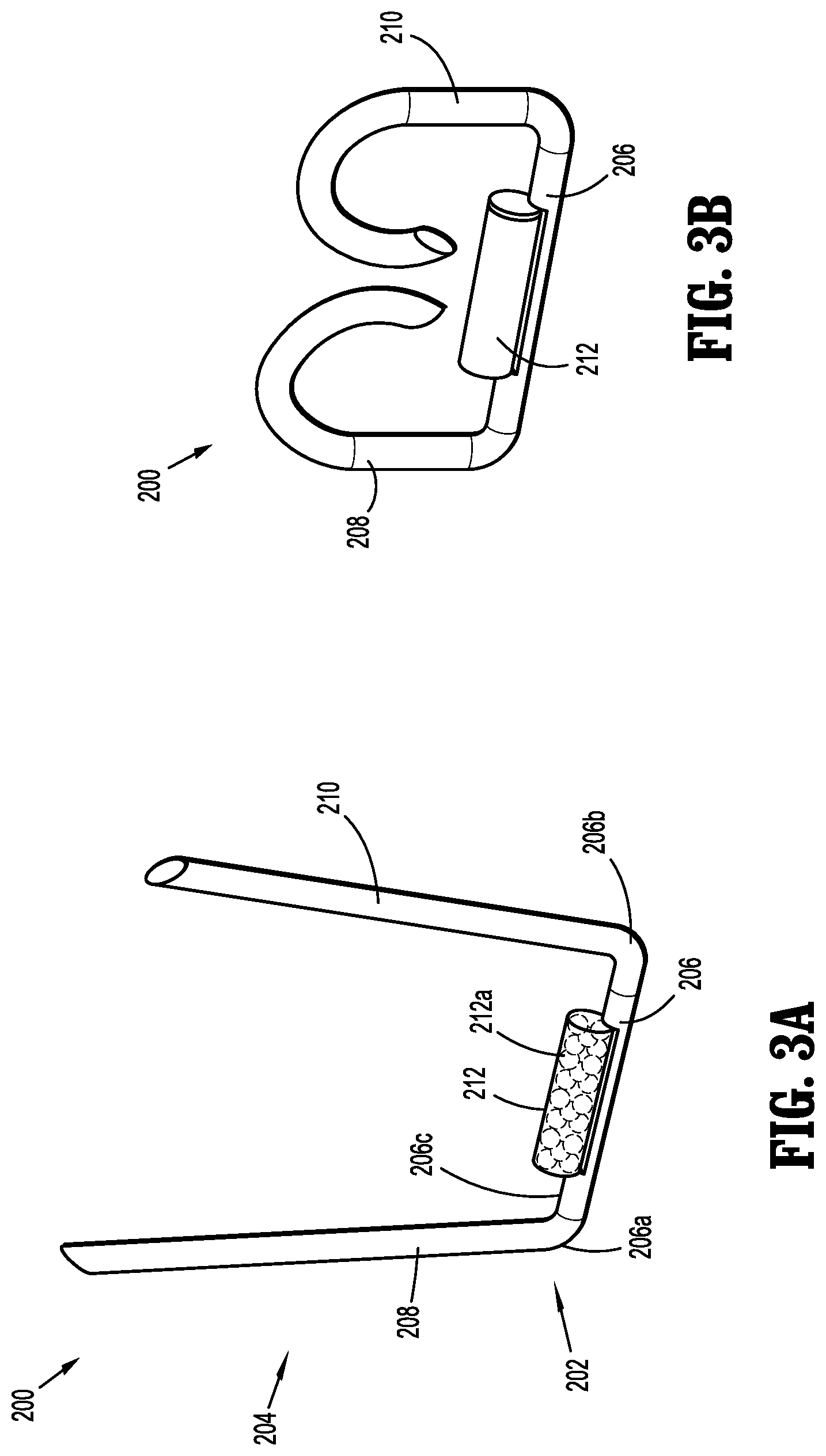
[0054] For example, with reference to FIGS. 3A and 3B, an implantable fastener in the form of a "B-shaped" surgical staple is shown and generally designated as 200. Similar to implantable fastener 100, implantable fastener 200 may generally include a body 202 and a tissue penetrating portion 204 extending from the body 202. The body 202 includes a crown or backspan 206 and the tissue penetrating portion 204 includes a first leg 208 extending from a first end portion 206a of the backspan 206 and a second leg 210 extending from a second end portion 206b of the backspan 206.
[0055] In accordance with the present disclosure, at least one capsule 212, similar to capsule 112, may be affixed to a tissue facing surface 206c of backspan 206. Capsule 212 may include a radioactive material 212a. Additionally or alternatively, it is further envisioned that implantable fastener 200 may be processed such that the entirety of implantable fastener 200 emits radiation from radioactive material dispersed throughout implantable fastener 200. For example, implantable fastener 200 may be processed so as to determine the strength of the emitted radiation.
[0056] Implantable fastener 200 may have an unformed condition, as shown in FIG. 3A, wherein the first leg 208 and the second leg 210 are parallel, or substantially parallel, to one another and spaced a relative distance from one another. Implantable fastener 200 may have a formed condition, as shown in FIG. 3B, wherein at least a portion of the first leg 208 and the second leg 210 are radiused and in relative close approximation to one another and backspan 206 to define a substantially B-shaped structure.
[0057] Implantable fastener 200 may be fabricated from, for example, titanium, stainless steel or polymers. In an embodiment, implantable fastener 200 may be a polymeric surgical pin fabricated from a radioactive biocompatible material. Some examples of non-degradable biocompatible polymers include polyolefins such as polyethylenes and polypropylenes, nylons, polyesters, silicones, polyimides, polymethylmethacrylates, polyphthalamides, polyurethanes, PTFE, polyethersulfone, polysulfone, PEEK, to name a few.
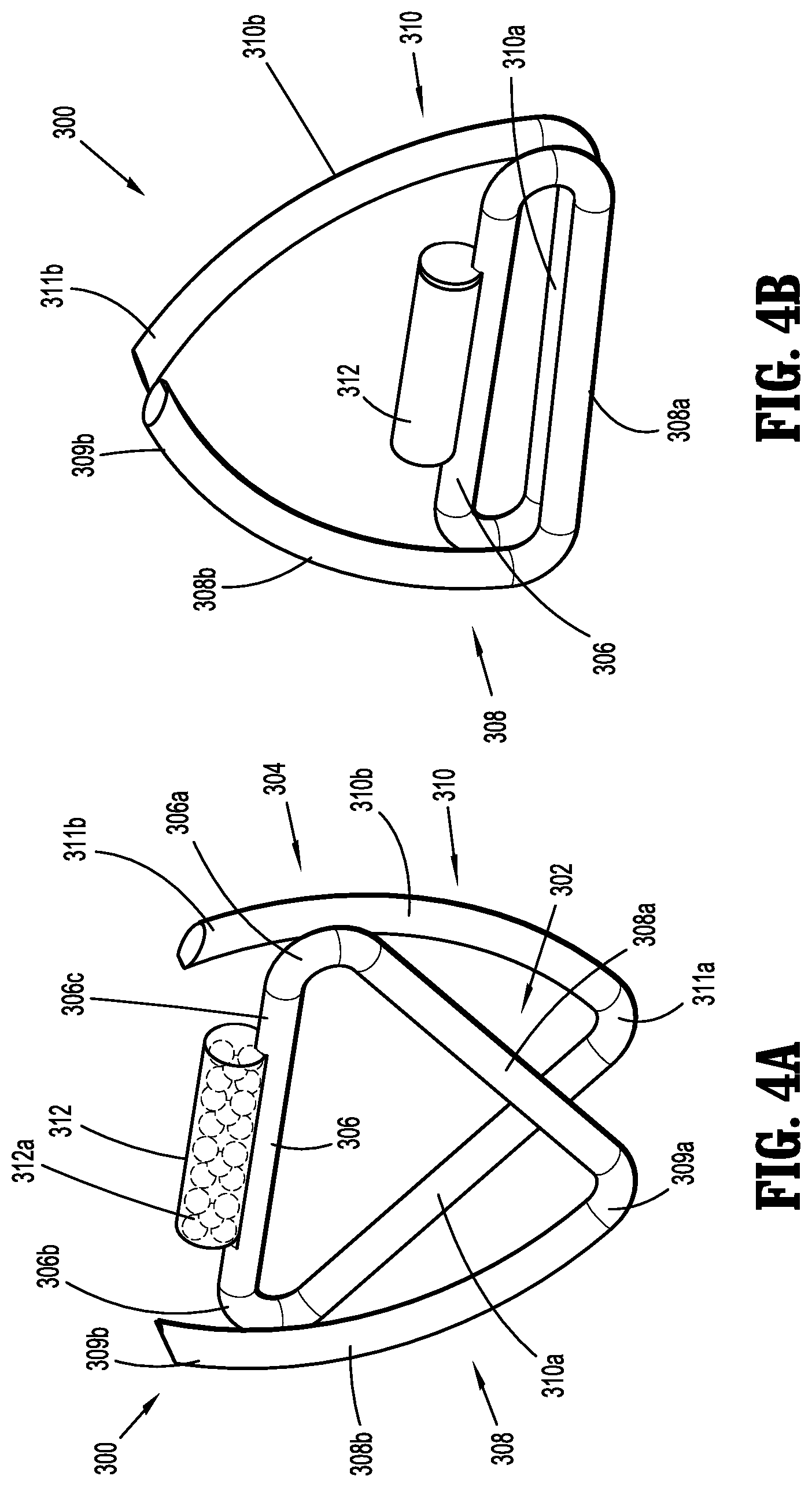
[0058] As an additional example, with reference to FIGS. 4A and 4B, an implantable fastener in the form of a "W-shaped" surgical staple is shown and generally designated as 300. Similar to implantable fasteners 100, 200, implantable fastener 300 may generally include a body 302 and a tissue penetrating portion 304 extending from the body 302. The body 302 includes a crown or backspan 306 and the tissue penetrating portion 304 includes a first leg 308 having a first portion 308a and a second portion 308b, and a second leg 310 having a first portion 310a and a second portion 310b. The first portion 308a of the first leg 308 extends from a first end portion 306a of backspan 306 and is coupled to a proximal end portion 309a of the second portion 308b of the first leg 308. Similarly, the first portion 310a of the second leg 310 extends from a second end portion 306b of backspan 306 and is coupled to a proximal end portion 311a of the second portion 3010b of the second leg 310.
[0059] In accordance with the present disclosure, at least one capsule 312, similar to capsules 112, 212, may be affixed to a tissue facing surface 306c of backspan 306. Capsule 312 may include a radioactive material 312a. Additionally or alternatively, it is further envisioned that implantable fastener 300 may be processed such that the entirety of implantable fastener 300 emits radiation from radioactive material dispersed throughout implantable fastener 300. It is contemplated that, implantable fastener 300 may be processed so as to determine the strength of the emitted radiation.
[0060] In an unformed condition, as shown in FIG. 4A, the backspan 306 is in a distal position relative to the proximal end portions 309a, 311a of the first and second legs 308, 310, respectively. Specifically, backspan 306 is in relative close proximity to a distal end portion 309b of the second portion 308b of the first leg 308 and a distal end portion 311b of the second portion 310b of the second leg 310. In the unformed condition, the first portions 308a, 310a of the first and second legs 308, 310, respectively, extend away from the backspan 306 at an angle such that the first portions 308a, 310a overlap one another, as shown in FIG. 4A. Further, in the unformed condition, the second portions 308b, 310b of the first and second legs 308, 310, respectively, are spaced a relative distance from one another and extend towards backspan 306.
[0061] In accordance with the present disclosure, implantable fastener 300 may have a formed condition, as shown in FIG. 4B, wherein the backspan 306 is in a proximal position relative to the distal end portions 309b, 311b of the first and second legs 308, 310, respectively. In the formed condition, at least a portion of the second portions 308b, 310b of the first and second legs 308, 310, respectively, are radiused and in relative close approximation to one another. In the formed condition, as shown in FIG. 4B, the first portions 308a, 310a of the first and second legs 308, 310, respectively, and the backspan 306 are parallel, or substantially parallel, to one another and, and in relative close approximation to one another and backspan 306. Further, in the formed condition, the backspan 306 is spaced a relative distance from the distal end portions 309b,311b of the second portions 308b, 310b of the first and second legs 308, 310, respectively.
[0062] As an additional example, with reference to FIG. 5, an implantable fastener in the form of a surgical coil is shown and generally designated as 400. Specifically, implantable fastener 400 is a helical-shaped coil fastener. Implantable fastener 400 is designed for application to tissue by rotating implantable fastener 400 into and through the target tissue. Implantable fastener 400 generally includes a coil body portion 402 terminating in a tissue penetrating portion 404. The tissue penetrating portion 404 includes a penetrating point 404a. It is contemplated that the coil body portion 402 may include one or more turns or coils.
[0063] Implantable fastener 400 includes a tang 406 at an opposite end of coil body portion 402 from tissue penetrating portion 404. Tang 406 extends generally inwardly toward the center of coil body portion 402 and includes a cavity 406a defined therein. The cavity 406a is capped or closed with a plug 408 having a size and shape corresponding to a size and shape of an opening of the cavity 406a of tang 406.
[0064] In accordance with the present disclosure, at least one capsule 410 may be disposed within cavity 406a of tang 406. Similar to capsules 112, 212, 312, capsule 410 includes a radioactive material 410a. Additionally or alternatively, the radioactive material 410a may be disposed within or onto coil body portion 402 of implantable fastener 400. It is further envisioned that implantable fastener 400 may be processed such that the entirety of implantable fastener 400 emits radiation from radioactive material 410a dispersed throughout implantable fastener 400. For example, and within the purview of the present disclosure, implantable fastener 400 may be processed so as to determine the strength of the emitted radiation.
[0065] With reference to FIG. 6, in embodiments, implantable fastener 400 may include at least one capsule 410' affixed to an outer surface of tang 406' using laser welding or other suitable methods. Specifically, tang 406' may include a flattened surface 406b extending along at least a portion thereof and configured to provide an increased surface area for affixing the capsule 410'. Additionally or alternatively, the at least one capsule 410' may be affixed to an outer surface of the coil body portion 402. Similar to capsules 112, 212, 312, 410, capsule 410' includes a radioactive material 410a' disposed therein. Capsule 410' is capped or closed with a plug 412 having a size and shape corresponding to a size and shape of an opening of the capsule 410'. In embodiments, plug 412 is an inverted cap affixed to opposite ends of capsule 410' using laser welding, adhesives, or other suitable methods. Alternatively, plug 412 may include any suitable configuration configured to retain the radioactive material 410a' disposed within the at least one capsule 410'.
[0066] In embodiments, an implantable fastener 800 is provided as illustrated in FIG. 7. Implantable fastener 800 is a helical-shaped coil fastener similar to the implantable fastener 400 illustrated in FIGS. 5 and 6. Accordingly, implantable fastener 800 generally includes a coil body portion 802 terminating in a tissue penetrating portion 804. The tissue penetrating portion 804 includes a penetrating point 804a. It is contemplated that the coil body portion 802 may include one or more turns or coils.
[0067] Implantable fastener 800 includes a tang 806 at an opposite end of coil body portion 802 from tissue penetrating portion 804. Tang 806 extends generally inwardly toward the center of coil body portion 802 and includes a crimped portion 808 configured to capture and retain at least one capsule 810 within a cavity 812 adjacent tang 806. In embodiments, the capsule 810 may be disposed adjacent tang 806 and the crimped portion 808 formed thereabout to secure the capsule 810 within cavity 812 via a friction fit engagement between the tang 806 and the crimped portion 808. Alternatively, the crimped portion 808 may be formed about tang 806 to define cavity 812 and the capsule 810 may be disposed therein. Additionally or alternatively, the capsule 810 may be secured within cavity 812 using laser welding or other suitable methods. In embodiments, at least one of the crimped portion 808 and the tang 806 may include a groove 814 extending along at least a portion thereof and configured to provide an increased surface area for affixing the capsule 810. Capsule 810 is similar to capsule 410' and is configured to retain a radioactive material 810a disposed therein.
[0068] Implantable fasteners 400, 800 may be fabricated from, for example, titanium, stainless steel or polymers. In an embodiment, implantable fasteners 400, 800 may be a polymeric surgical coil fabricated from a radioactive biocompatible material.
[0069] With reference to FIG. 8, an implantable fastener in the form of an "S-shaped" fastener is shown and generally designated as 900. Implantable fastener 900 generally includes a body 902, a first leg 904, and a second leg 906. Body 902 defines a longitudinal axis "A1-A1" and includes a first end portion 902a, an opposing second end portion 902b, and a cannula 902c extending longitudinally therebetween.
[0070] The first leg 904 includes a first tissue penetrating portion 908 having a first tissue penetrating tip 908a and the second leg 906 includes a second tissue penetrating portion 910 having a second tissue penetrating tip 910a. The first leg 904 extends generally from the first end portion 902a of body 902 and radially towards the second end portion 902b of body 902 such that the first tissue penetrating tip 908a is disposed adjacent the second end portion 902b of body 902. Similarly, second leg 906 extends generally from the second end portion 902b of body 902 and radially towards the first end portion 902a of body 902 such that the second tissue penetrating tip 910a is disposed adjacent the first end portion 902a of body 902. It is contemplated that the first and second tissue penetrating tips 908a, 910a may be disposed on either the same lateral side of longitudinal axis "A1-A1", as shown in FIG. 8, or on opposing lateral sides of longitudinal axis "A1-A1".
[0071] In accordance with the present disclosure, at least one capsule 912 may be disposed within cannula 902c of body 902 and secured therein via a press fit engagement, a friction fit engagement, or other suitable methods. Capsule 912 is similar to capsules 410', 810 and is configured to retain a radioactive material 912a disposed therein. With brief reference to FIG. 16, in embodiments, capsule 912' is disposed within cannula 902c' of implantable fastener 900' before the implantable fastener 900' is loaded into a cartridge assembly 720'. Alternatively, capsule 912 may be disposed within cannula 902c of body 902 after the implantable fastener 900 is loaded into the cartridge assembly, as will be detailed below.
[0072] Implantable fastener 900 may be fabricated from, for example, titanium, stainless steel or polymers. In embodiments, the polymer may include a biodegradable polymer with an approximately four to five week in vivo strength retention profile.
[0073] While implantable fasteners in the form of a surgical staple and, a surgical coil or the like, have been illustrated and described herein, it is within the scope of the present disclosure that the implantable fasteners may also include two-part fasteners, tacks, locking hinged fasteners, staples or the like. For example, in one embodiment, the implantable fastener may include a two-part polymeric fastener having a coating of polymeric and/or radioactive material.
[0074] In order to place implantable fasteners 100 disclosed herein, in accordance with the present disclosure, as illustrated in FIG. 9, a surgical apparatus in the form of a fastener applicator 500 is provided. For a more detailed description of the construction and operation of an example of fastener applicator 500, reference may be made to U.S. Pat. No. 7,624,903, the entire content of which is incorporated herein by reference.
[0075] Fastener applicator 500 includes a body portion 510 having a handle assembly 520, an endoscopic shaft assembly 530 extending from handle assembly 520, a cartridge assembly 540 extending from endoscopic shaft assembly 530, and an actuation assembly 550 at least partially supported within the handle assembly 520.
[0076] Endoscopic shaft assembly 530 is rotatably connected to handle assembly 520 such that endoscopic shaft assembly 530 is rotatable about a longitudinal axis "X1-X1" thereof. Cartridge assembly 540 is pivotably connected to a distal end portion of endoscopic shaft assembly 530 and is pivotable relative to the longitudinal axis "X1-X1" of endoscopic shaft assembly 530. In FIG. 9, cartridge assembly 540 is shown in general alignment with the longitudinal axis "X1-X1" of endoscopic shaft assembly 530 and additionally in phantom to illustrate a range of movement or articulation. The total range of pivotal motion of cartridge assembly 540 as shown is approximately 90 degrees, i.e. 45 degrees to each side of neutral.
[0077] Referring to FIG. 10, the endoscopic shaft assembly 530 is shown in an exploded view with parts separated for convenience of illustration and includes an upper housing half section 530a and a lower housing half section 530b. Positioned within the upper and lower housing half sections 530a, 530b, is a drive assembly 531. Drive assembly 531 generally includes a pusher or drive beam 532 and an anvil extension 533, and is operatively coupled to the cartridge assembly 540 to engage implantable fasteners 100 supported in the cartridge assembly 540.
[0078] With additional reference to FIG. 11, drive beam 532 has a pusher plate 534 configured to engage a distal-most implantable fastener 100 of the implantable fasteners 100 upon actuation of the actuation assembly 550. As shown in FIG. 11, anvil extension 533 includes a distal end portion 533a that is provided to pivotably couple the cartridge assembly 540 via a pivot pin 533b.
[0079] With continued reference to FIG. 11, cartridge assembly 540 is adapted to support the implantable fasteners 100. In accordance with the present disclosure, the implantable fasteners 100 are positioned in adjacent stacked relation. In one embodiment, the implantable fasteners 100 are stacked such that an angle of approximately 45 degrees is formed relative to the longitudinal axis "X1-X1" (see FIG. 12). Cartridge assembly 540 further includes an anvil plate 542, for forming the implantable fastener 100 therearound.
[0080] Referring now to FIGS. 12 and 13, advancing and firing of an implantable fastener 100 is illustrated. Upon initial actuation of the actuation assembly 550, the pusher plate 534 is advanced distally and the distal-most implantable fastener 100 is advanced distally of the implantable fasteners 100 in a manner such that pusher plate 534 replaces the distal-most implantable fastener 100 thereby preserving the integrity and position of the stack of the implantable fasteners 100. It is contemplated that pusher plate 534 engages only one implantable fastener 100 at a time.
[0081] Upon further actuation of the actuation assembly 550, plusher plate 534 is advanced distally sufficient to cause the distal-most implantable fastener 100 to penetrate tissue and form thereon to secure capsule 112. Specifically, pusher plate 534 includes a pair of lands 534a, 534b to facilitate transmission of advancing force to the first and second end portions 106a, 106b of the backspan 106. Anvil plate 542 is positioned for engagement with backspan 106 such that engagement of implantable fastener 100 by the pair of lands 534a, 534b of pusher plate 534 with the first and second end portions 106a, 106b of the implantable fastener 100 will cause the implantable fastener 100 to form and secure about tissue in a predetermined manner.
[0082] In order to place implantable fasteners 200, 300 disclosed herein, in accordance with the present disclosure, as illustrated in FIG. 14, a surgical apparatus in the form of a fastener applicator 600 is provided. For a more detailed description of the construction and operation of an example of fastener applicator 600, reference may be made to U.S. Pat. No. 8,403,946, the entire content of which is incorporated herein by reference.
[0083] Fastener applicator 600 includes a handle assembly 610, and an endoscopic shaft assembly 620 extending from handle assembly 610. Endoscopic shaft assembly 620 is rotatably connected to handle assembly 610 such that endoscopic shaft assembly 620 is rotatable about a longitudinal axis "X2-X2" thereof. Endoscopic shaft assembly 620 may include a proximal portion 622, and a distal portion 624. An end effector 626 is pivotably connected to distal portion 624, wherein end effector 626 may be articulated relative to distal portion 624.
[0084] End effector 626 of endoscopic shaft assembly 620 may include a quantity of implantable fasteners 200, 300 (not shown) pre-loaded therein, or may be configured to selectively receive a cartridge assembly (not shown) which is loaded with a quantity of implantable fasteners 200, 300 therein. For example, the cartridge assembly may be loaded with ten or fewer implantable fasteners 200, 300, or any quantity of implantable fasteners 200, 300.
[0085] End effector 626 of endoscopic shaft assembly 620 may include a drive assembly configured to load a single, distal-most implantable fastener 200, 300 into a pair of jaws 628, and to form the implantable fastener 200, 300 loaded into the pair of jaws 628. Fastener applicator 600 is configured to fire and form a single implantable fastener 200, 300 during a complete firing sequence. In any of the embodiments disclosed herein, the fastener instrument can be an open stapler, an endoscopic stapler, clip applier instrument, or other types of surgical instruments. In certain embodiments, the fasteners disclosed herein can be used in a robotic surgical system or with motorized surgical instruments to apply one fastener at a time, or multiple fasteners at a time. In any of the embodiments disclosed herein, the fastener applier can be configured to allow the surgeon to decide how many fasteners to apply, and where, and how many radioactive capsules to apply, or other types of medically or pharmaceutically active capsules to apply.
[0086] In order to place implantable fasteners 400, 800, 900 in accordance with the present disclosure, as illustrated in FIG. 15, a surgical apparatus in the form of a fastener applicator 700 is provided. For a more detailed description of the construction and operation of an example of a fastener applicator 700 capable of firing implantable fasteners 400, 800, 900 reference may be made to U.S. Pat. No. 5,830,221, the entire content of which is incorporated herein by reference. Fastener applicator 700 may be provided either pre-loaded with implantable fasteners 400, 800, or may be configured to selectively receive a cartridge assembly 720 loaded with implantable fasteners 400, 800.
[0087] With reference to FIG. 16, in embodiments, the fastener applicator 700 (FIG. 15) may be configured to selectively receive cartridge assembly 720' preloaded with a plurality of implantable fasteners 900. Cartridge assembly 720' includes a plurality of ports 740 extending through an outer surface thereof. Each port 740 is configured and dimensioned to longitudinally align with the respective cannula 902c of body 902 of each implantable fastener 900 preloaded into the cartridge assembly 720'. With the plurality of implantable fasteners 900 preloaded into the cartridge assembly 720', the plurality of capsules 912 may be inserted through the plurality of ports 740 and disposed within the respective cannulas 902c of the plurality of implantable fasteners 900. This configuration facilitates efficient loading of the plurality of implantable fasteners 900 with the plurality of capsules 912 without having to handle each implantable fastener 900 individually. It is contemplated that this configuration may facilitate field customization of the payload.
[0088] The fastener applicator 700 may be configured to fire or deliver implantable fasteners 400, 800, 900 during a full firing sequence. The fastener applicator 700 may also be configured to articulate in order to facilitate the firing of implantable fasteners 400, 800, 900 therefrom.
[0089] In accordance with the present disclosure, the combination of implantable fasteners and fastener applicators disclosed herein provides a clinician a relatively great deal of flexibility and customization in placing radiation emitting implants, such as, for example, implantable fasteners 100, 200, 300, 400, 800, 900 at desired target surgical sites, whereby the fastener applicator, such as, for example, fastener applicator 500 is articulatable and/or rotatable to provide the clinician with increased flexibility and precision in placing the radiation emitting implants. It is also contemplated that the fasteners could dispense other types of medical treatments such as pharmaceutically active agents.
[0090] It is contemplated for example, that a geometry of implantable fasteners 100, 200, 300, 400, 800, 900; and a geometry of a fastener applicator 500, 600, 700 may be optimized to work together as location guides to optimally place implantable fasteners 100, 200, 300, 400, 800, 900 adjacent to one another, wherein the capsules 112, 212, 316, 410, 410', 810, 912 has a known geometry and radiation field strength, to achieve effective dosimetry.
[0091] In accordance with the present disclosure, the location of placement of implantable fasteners 100, 200, 300, 400, 800, 900 is not limited to a predefined geometry, pattern, density, or the like. In particular, as mentioned above, implantable fasteners 100, 200, 300, 400, 800, 900 may be fastened to a target tissue site in any geometry, pattern and/or density, as the clinician desires or needs.
[0092] By way of example, the ability to fasten implantable fasteners 100, 200, 300, 400, 800, 900 to a target tissue site, such as, for example, lung tissue in a lung resection procedure, in any geometry, pattern and/or density, may be quite useful in a lung cancer patient, where many lung cancer patients suffer from impaired lung volume and cannot tolerate unnecessary loss of lung volume, and may need multiple rows of brachytherapy sources to ensure treatment of an inadequately narrow surgical margin.
[0093] In any of the embodiments disclosed herein, the implantable fasteners 100, 200, 300, 400, 800, 900 may be incorporated into, or configured for use with, devices that are part of a powered surgical system or robotic surgical system.
[0094] It will be understood that various modifications may be made to the embodiments disclosed herein. Therefore, the above description should not be construed as limiting, but merely as exemplifications of preferred embodiments. Those skilled in the art will envision other modifications within the scope and spirit of the claims appended thereto.
* * * * *
D00000
D00001
D00002
D00003
D00004
D00005
D00006
D00007
D00008
D00009
D00010
D00011
D00012
D00013
XML
uspto.report is an independent third-party trademark research tool that is not affiliated, endorsed, or sponsored by the United States Patent and Trademark Office (USPTO) or any other governmental organization. The information provided by uspto.report is based on publicly available data at the time of writing and is intended for informational purposes only.
While we strive to provide accurate and up-to-date information, we do not guarantee the accuracy, completeness, reliability, or suitability of the information displayed on this site. The use of this site is at your own risk. Any reliance you place on such information is therefore strictly at your own risk.
All official trademark data, including owner information, should be verified by visiting the official USPTO website at www.uspto.gov. This site is not intended to replace professional legal advice and should not be used as a substitute for consulting with a legal professional who is knowledgeable about trademark law.