Seals For Surgical Access Assemblies
Kind Code
U.S. patent application number 16/272068 was filed with the patent office on 2020-08-13 for seals for surgical access assemblies. The applicant listed for this patent is Covidien LP. Invention is credited to Jacob C. Baril, Eric Brown, Kevin Desjardin, Matthew A. Dinino, Garrett P. Ebersole, Nicolette R. LaPierre, Roy J. Pilletere, Justin Thomas.
| Application Number | 20200253634 16/272068 |
| Document ID | 20200253634 / US20200253634 |
| Family ID | 1000003975907 |
| Filed Date | 2020-08-13 |
| Patent Application | download [pdf] |


| United States Patent Application | 20200253634 |
| Kind Code | A1 |
| Pilletere; Roy J. ; et al. | August 13, 2020 |
SEALS FOR SURGICAL ACCESS ASSEMBLIES
Abstract
Access assemblies includes an instrument valve housing and a valve assembly disposed within the cavity of the instrument valve housing. The valve assembly includes a guard assembly, a seal assembly disposed adjacent to the guard assembly, and a centering mechanism for maintaining the seal assembly and guard assembly centered within a cavity of the instrument valve. In embodiments, the seal assembly includes a plurality of seal sections that are movable from an unfolded configuration to folded configuration in which the seal assembly forms a hexagonal member defining an opening to facilitate sealed passage of a surgical instrument. The seal sections may include a tapered inner edge for engaging a surgical instrument inserted through the instrument valve housing.
| Inventors: | Pilletere; Roy J.; (North Haven, CT) ; Dinino; Matthew A.; (Newington, CT) ; Ebersole; Garrett P.; (Hamden, CT) ; Desjardin; Kevin; (Cheshire, CT) ; Thomas; Justin; (New Haven, CT) ; Baril; Jacob C.; (Norwalk, CT) ; LaPierre; Nicolette R.; (Windsor Locks, CT) ; Brown; Eric; (Haddam, CT) | ||||||||||
| Applicant: |
|
||||||||||
|---|---|---|---|---|---|---|---|---|---|---|---|
| Family ID: | 1000003975907 | ||||||||||
| Appl. No.: | 16/272068 | ||||||||||
| Filed: | February 11, 2019 |
| Current U.S. Class: | 1/1 |
| Current CPC Class: | A61B 17/3423 20130101; A61B 17/3498 20130101 |
| International Class: | A61B 17/34 20060101 A61B017/34 |
Claims
1. An access assembly comprising: an instrument valve housing including upper, lower, and inner housing sections and defining a cavity; and a valve assembly disposed within the cavity of the instrument valve housing, the valve assembly including: a guard assembly including a plurality of guard sections, a seal assembly disposed adjacent to the guard assembly, the seal assembly including a plurality of seal sections, the plurality of seal sections being movable from an unfolded configuration to folded configuration in which the seal assembly forms a hexagonal member defining an opening to facilitate sealed passage of a surgical instrument; and a centering mechanism for maintaining the seal assembly and guard assembly centered within the cavity of the instrument valve.
2. The access assembly of claim 1, wherein the opening in the seal assembly has a diameter between 0.025'' and 0.100''.
3. The access assembly of claim 1, wherein the seal assembly includes six seal sections.
4. The access assembly of claim 1, wherein the plurality of seal sections are formed of polyisoprenes or silicone elastomers.
5. The access assembly of claim 1, wherein seal sections of the plurality of seal sections are connected to adjacent seal sections of the plurality of seal sections by connector portions.
6. The access assembly of claim 1, wherein the connector portions include living hinges
7. The access assembly of claim 1, wherein each seal section of the plurality of seal sections includes a wing shape.
8. The access assembly of claim 1, wherein an inner edge of each seal section of the plurality of seal sections is straight.
9. The access assembly of claim 1, wherein an inner edge of each seal section of the plurality of seal sections defines a V-shape.
10. The access assembly of claim 9, wherein the V-shape includes an angle between one hundred eighty degrees and two hundred seventy-five degrees.
11. The access assembly of claim 1, wherein an inner edge of each seal section of the plurality of seal sections is tapered.
12. The access assembly of claim 1, wherein the plurality of seal sections includes first, second, third, fourth, fifth, and sixth seal sections, each of the first, second, third, fourth, fifth, and sixth seal sections overlapping the adjacent second, third, fourth, fifth, sixth, and first seal sections.
13. The access assembly of claim 1, further including a retainer assembly including upper and lower retainer members.
14. The access assembly of claim 13, wherein at least one of the upper and lower retainer members includes a plurality of pins receivable through the guard assembly and seal assembly for retaining the guard and seal assemblies relative to each other.
15. The access assembly of claim 1, wherein the centering mechanism includes a bellows.
Description
BACKGROUND
Technical Field
[0001] The present disclosure relates to access assemblies for minimally invasive surgery, including seals. More particularly, the present disclosure relates to seals for surgical access assemblies.
Background
[0002] In order to facilitate minimally invasive surgery, a working space must be created in the desired surgical space. An insufflation gas, typically CO.sub.2, is introduced into the abdomen of the patient to create an inflated state called a pneumoperitoneum. Access assemblies are utilized to allow the introduction of surgical instrumentation and endoscopes (or other visualization tools). These access assemblies maintain the pressure for the pneumoperitoneum, as they have one or more seals that adapt to the surgical instrumentation. Typically, a "zero-seal" in the access assembly seals the access assembly in the absence of a surgical instrument in the access assembly, and an instrument seal seals around a surgical instrument that has been inserted through the access assembly.
[0003] The breadth of surgical instrumentation on the market today requires a robust seal capable adjusting to multiple sizes and withstanding multiple insertions of surgical instrumentation. Some of the instrumentation can include sharp edges that can tear or otherwise damage seals. Therefore, it would be beneficial to have an access assembly with improved seal durability.
SUMMARY
[0004] An access assembly with an improved seal durability is provided. The access assembly includes an instrument valve housing and a valve assembly. The instrument valve housing includes upper, lower, and inner housing sections and defines a cavity. The valve assembly is disposed within the cavity of the instrument valve housing. The valve assembly includes a guard assembly, a seal assembly disposed adjacent to the guard assembly, and a centering mechanism for maintaining the seal assembly and guard assembly centered within the cavity of the instrument valve. The guard assembly includes a plurality of guard sections. The seal assembly is disposed adjacent to the guard assembly, the seal assembly including a plurality of seal sections, the plurality of seal sections being movable from an unfolded configuration to folded configuration in which the seal assembly forms a hexagonal member defining an opening to facilitate sealed passage of a surgical instrument.
[0005] In embodiments, an opening in the seal assembly has a diameter between 0.025'' and 0.100''. The seal assembly may include six seal sections. The plurality of seal sections may be formed of polyisoprenes or silicone elastomers. Seal sections of the plurality of seal sections may be connected to adjacent seal sections of the plurality of seal sections by connector portions. The connector portions may include living hinges. Each seal section of the plurality of seal sections may include a wing shape.
[0006] In some embodiments, an inner edge of each seal section of the plurality of seal sections is straight. Alternatively, the inner edge of each seal section of the plurality of seal sections defines a V-shape. The V-shape may include an angle between one hundred eighty degrees and two hundred seventy-five degrees. The inner edge of each seal section of the plurality of seal sections may be tapered. The plurality of seal sections may include first, second, third, fourth, fifth, and sixth seal sections. Each of the first, second, third, fourth, fifth, and sixth seal sections may overlap the adjacent second, third, fourth, fifth, sixth, and first seal sections.
[0007] The access assembly may further include a retainer assembly including upper and lower retainer members. At least one of the upper and lower retainer members may include a plurality of pins receivable through the guard assembly and seal assembly for retaining the guard and seal assemblies relative to each other. The centering mechanism may include a bellows.
BRIEF DESCRIPTION OF THE DRAWINGS
[0008] The accompanying drawings, which are incorporated in and constitute a part of this specification, illustrate embodiments of the disclosure and, together with a general description of the disclosure given above, and the detailed description of the embodiments given below, serve to explain the principles of the disclosure, wherein:
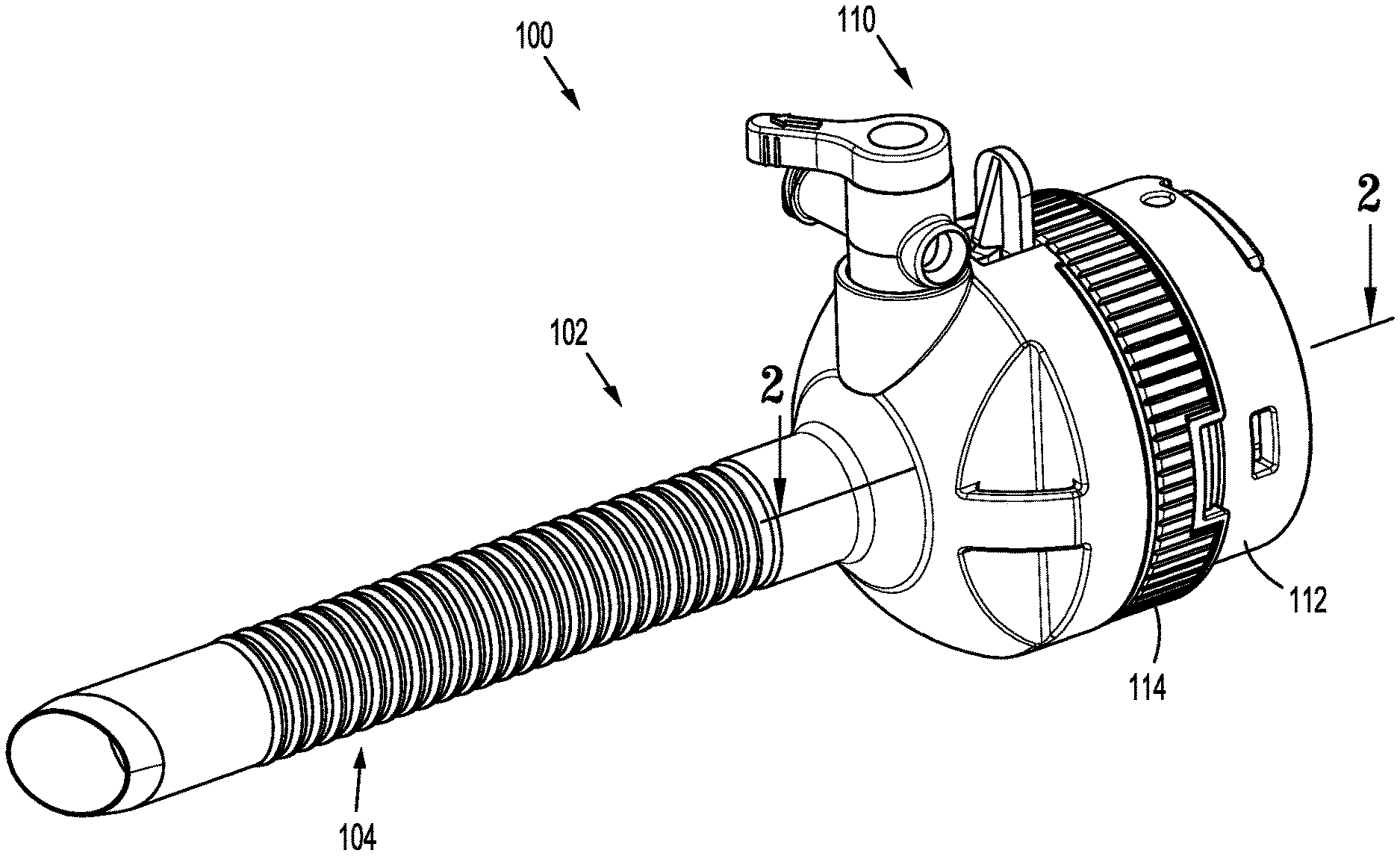
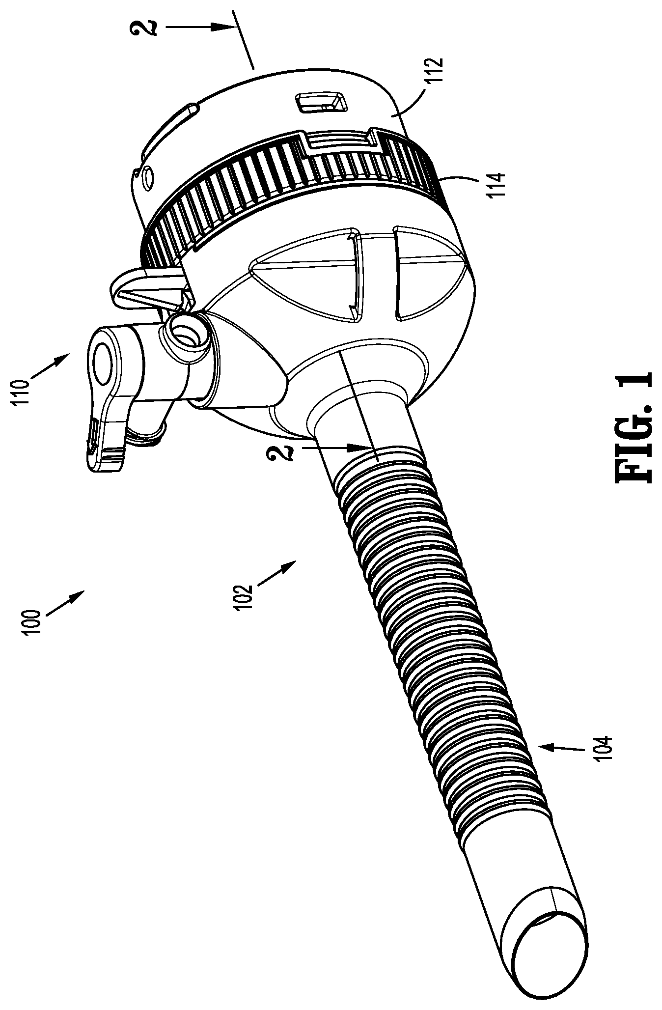
[0009] FIG. 1 is a side perspective view of an access assembly according to an embodiment of the present disclosure;
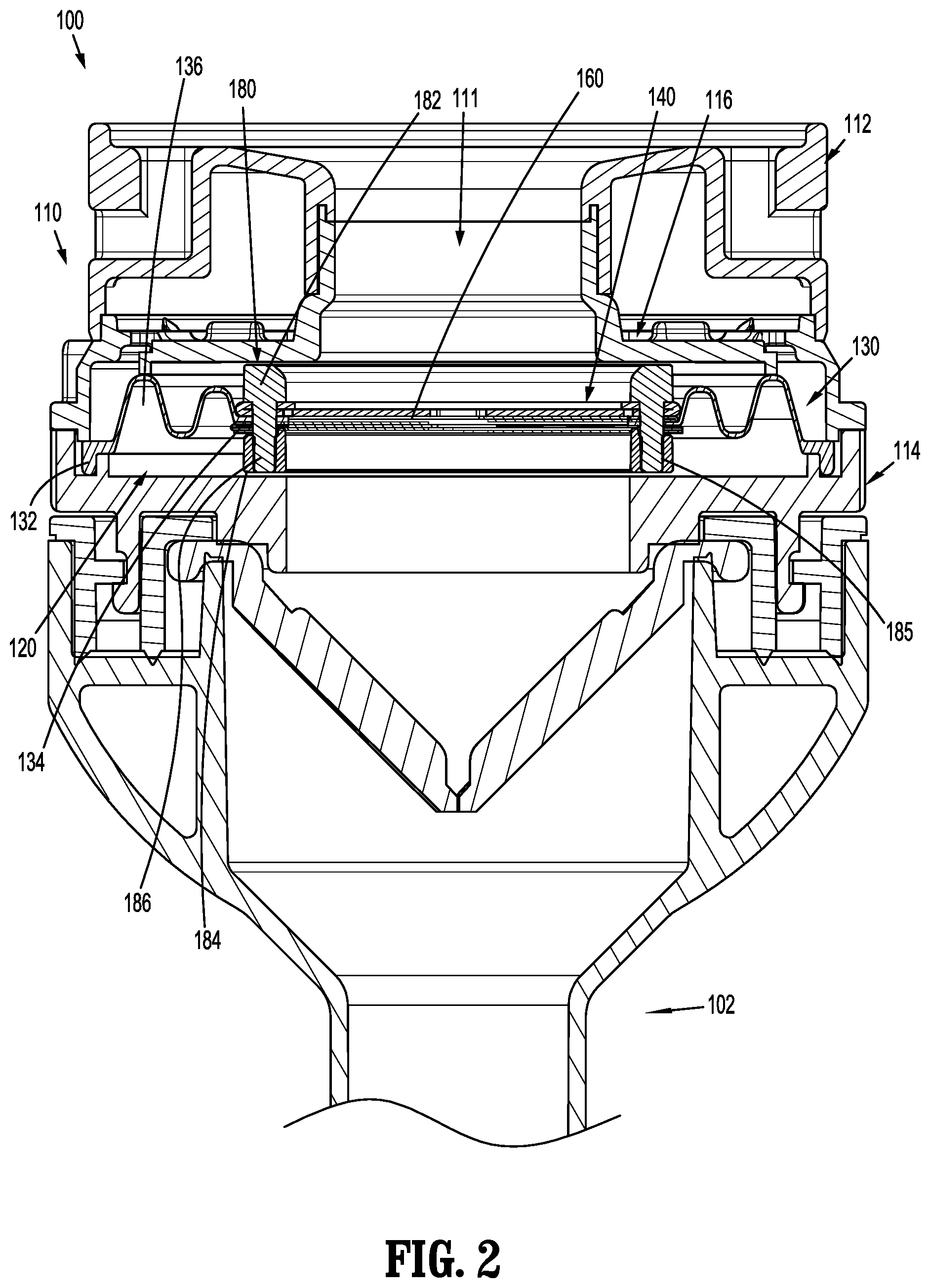
[0010] FIG. 2 a side cross-sectional view of the access assembly shown in FIG. 1 taken along section line 2-2;
[0011] FIG. 3 is an exploded perspective view of a valve assembly, including a centering mechanism, a guard assembly, a seal assembly, and a retainer assembly;
[0012] FIG. 4 is a perspective view of the seal assembly shown in FIG. 3;
[0013] FIG. 5 is a perspective view of the seal assembly shown in FIG. 3, in an unfolded configuration;
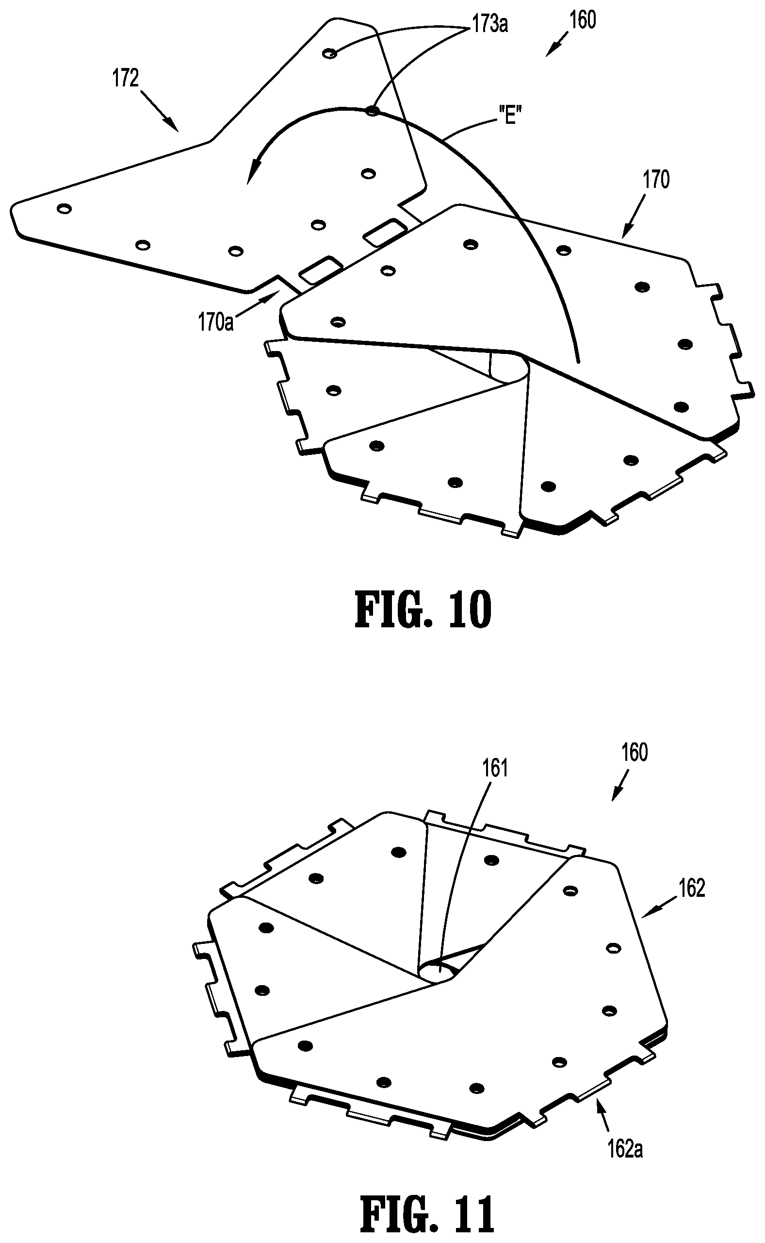
[0014] FIG. 6-11 are perspective views of the seal assembly shown in FIG. 3, in sequential partially folded conditions;
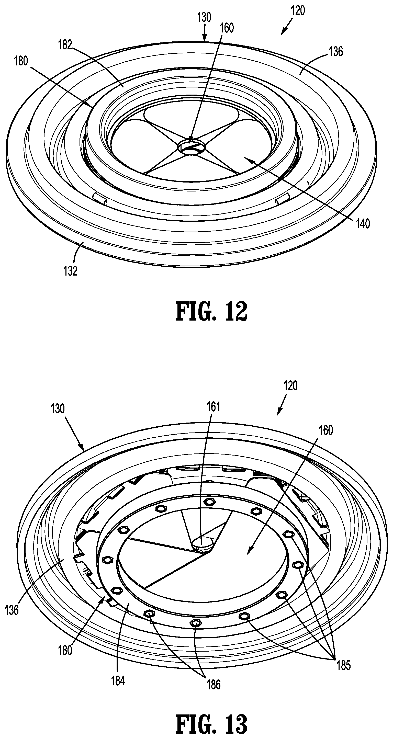
[0015] FIG. 12 is a top perspective view of the valve assembly shown in FIG. 3;
[0016] FIG. 13 is a bottom perspective view of the valve assembly shown in FIG. 3;
[0017] FIG. 14 is a top view of a seal assembly according to another embodiment of the present disclosure, in an initial or unfolded configuration;
[0018] FIG. 15 is a perspective side view of a section of the seal assembly shown in FIG. 14;
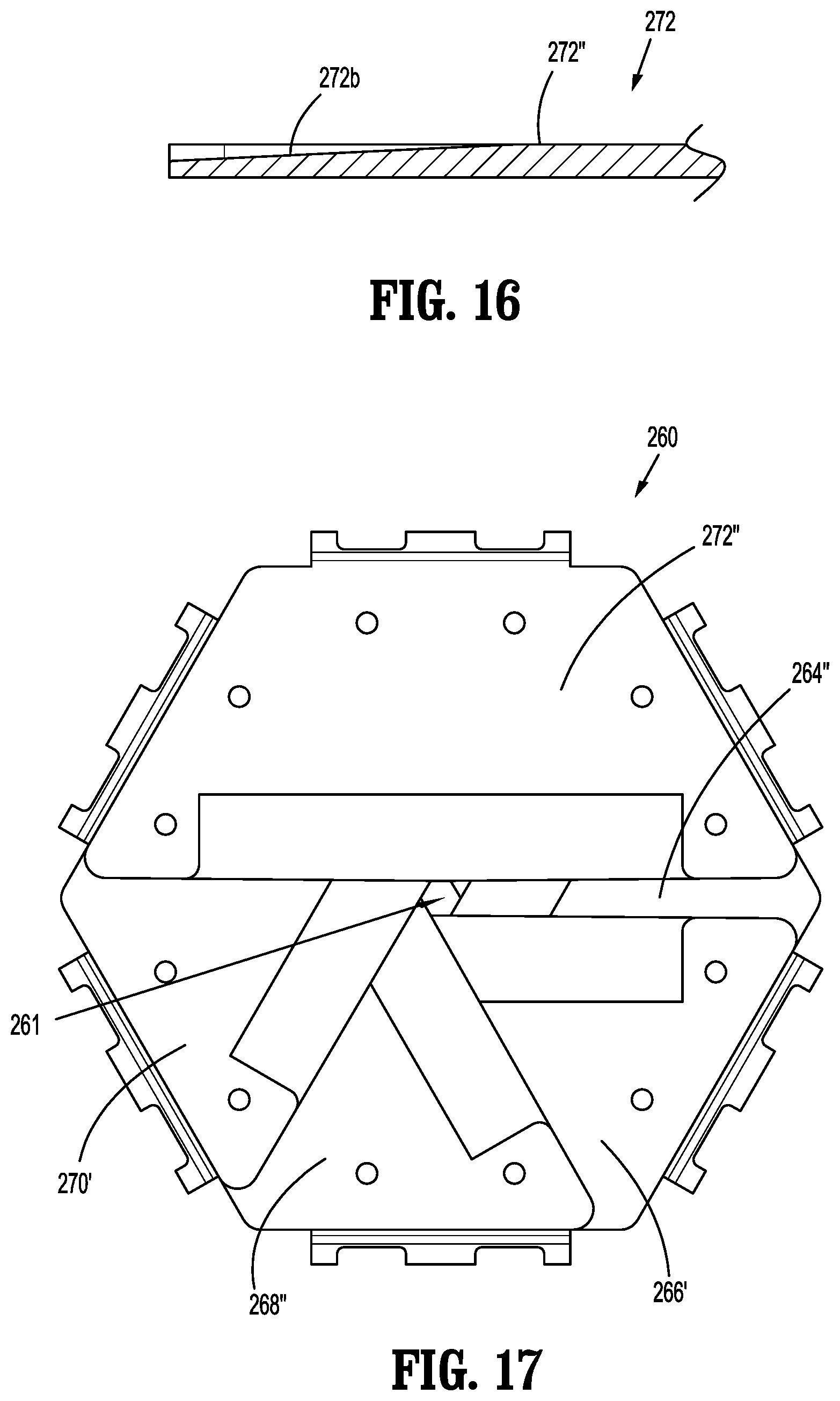
[0019] FIG. 16 is a side cross-sectional view of a section the seal assembly shown in FIG. 14 taken along section line 16-16 shown in FIG. 15;
[0020] FIG. 17 is a top view of the seal assembly shown in FIG. 14, in a folded configuration.
DETAILED DESCRIPTION
[0021] Particular embodiments of the present disclosure are described hereinbelow with reference to the accompanying drawings; however, it is to be understood that the disclosed embodiments are merely exemplary of the disclosure and may be embodied in various forms. Well-known functions or constructions are not described in detail to avoid obscuring the present disclosure in unnecessary detail. Therefore, specific structural and functional details disclosed herein are not to be interpreted as limiting, but merely as a basis for the claims and as a representative basis for teaching one skilled in the art to variously employ the present disclosure in virtually any appropriately detailed structure. Like reference numerals refer to similar or identical elements throughout the description of the figures.
[0022] As used herein, the term "distal" refers to that portion of the instrument, or component thereof which is farther from the user while the term "proximal" refers to that portion of the instrument or component thereof which is closer to the user.
[0023] Access assemblies with obturators are employed during minimally invasive surgery, e.g., laparoscopic surgery, and provide for the sealed access of surgical instruments into an insufflated body cavity, such as the abdominal cavity. The access assemblies of the present disclosure include an instrument valve housing mounted on a cannula tube, and include an obturator (not shown) inserted through the valve housing and cannula. The obturator can have a blunt distal end, or a bladed or non-bladed penetrating distal end and can be used to incise the abdominal wall so that the access assembly can be introduced into the abdomen. The handle of the obturator can engage or selectively lock into the instrument valve housing of the access assembly.
[0024] Access assemblies are employed to tunnel through an anatomical structure, e.g., the abdominal wall, either by making a new passage through the anatomical structure or by passing through an existing opening through the anatomical structure. Once the trocar assembly with the obturator has tunneled through the anatomical structure, the obturator is removed, leaving the access assembly in place. The instrument valve housing of the access assembly includes valves that prevent the escape of insufflation gases from the body cavity, while also allowing surgical instruments to be inserted into the cavity.
[0025] In various embodiments, a bladeless optical trocar obturator may be provided that permits separation of tissue planes in a surgical procedure and visualization of body tissue fibers as they are being separated, thereby permitting a controlled traversal across a body wall. In other embodiments, the trocar obturator may be bladeless without being optical, e.g., without providing contemporaneous visualization thereof through the distal tip of an obturator. The bladeless obturator may be provided for the blunt dissection of the abdominal lining during a surgical procedure.
[0026] Various trocar obturators suitable for use with the access assembly of the present disclosure are known and include, for example, bladed, bladeless, blunt, optical, and non-optical. For a detailed description of the structure and function of exemplary trocar assemblies, including exemplar trocar obturators and exemplar cannulas, please refer to commonly owned PCT Publication No. WO 2016/186905 ("the '905 publication"), the content of which is hereby incorporated by reference herein in its entirety.
[0027] With initial reference now to FIG. 1, an access assembly according to aspects of the present disclosure is shown generally as access assembly 100. The access assembly 100 includes a cannula 102 and an instrument valve housing 110 secured to the cannula 102. For a detailed description of an exemplary access assembly, please refer to the '905 publication.
[0028] With reference to FIG. 2, the instrument valve housing 110 of the access assembly 100 includes an upper housing section 112, a lower housing section 114, and an inner housing section 116. The upper, lower, and inner housing sections 112, 114, 116 are configured to support a valve assembly 120 on a proximal end of the cannula 102. More particularly, the inner housing section 116 is secured between the upper and lower housing sections 112, 114, and the valve assembly 120 is received between the inner and lower housing sections 116, 114. The upper and lower housing section 112, 114 of the instrument valve housing 110 may be selectively attachable to, and detachable from, the inner housing section 116. The lower housing section 114 may be releasably or permanently attached to a cannula tube 104 (FIG. 1) of the access assembly 102. In embodiments, either or both of the upper and lower housing sections 112, 114 of the instrument valve housing 110 may include knurls, indentations, tabs, or be otherwise configured to facilitate engagement by a clinician.
[0029] The access assembly 100 may also include features for the stabilization of the access assembly. For example, the distal end of the cannula tube 104 may carry a balloon anchor or another expandable member that engages the abdomen from the interior side. For example, see commonly owned U.S. Pat. No. 7,300,448, the entire disclosure of which is hereby incorporated by reference herein. A feature on the opposite side of the abdominal wall may be used to further stabilize the access assembly, such as adhesive tabs or adjustable foam collars.
[0030] The upper, lower, and inner housing sections 112, 114, 116 of the instrument valve housing 110 define a longitudinal passage 111 for receipt of a surgical instrument (not shown). The valve assembly 120 is supported within the instrument valve housing 110 to provide sealed passage of the surgical instrument through the access assembly 100.
[0031] With particular reference to FIGS. 2 and 3, the valve assembly 120 supported in the instrument valve housing 110 (FIG. 2) includes a centering mechanism 130, a guard assembly 140, a seal assembly 160, and a retainer assembly 180. The centering mechanism 130 of the valve assembly 120 permits radial movement of the valve assembly 120 relative to the instrument valve housing 110 when a surgical instrument is received through the valve assembly 120, and returns the valve assembly 120 to a generally centered position once the surgical instrument is withdrawn from within the instrument valve housing 110. The guard assembly 140 protects the seal assembly 160 during insertion and withdrawal of a surgical instrument through the seal assembly 160. The seal assembly 160 provides sealed passage of the surgical instrument through the instrument valve housing 110. The retainer assembly 180 maintains the centering mechanism 130, the guard assembly 140, and the seal assembly 160 in an aligned relationship with one another.
[0032] With continued reference to FIGS. 2 and 3, as noted above, the centering mechanism 130 of the valve assembly 120 is configured to maintain the valve assembly 120 centered within the instrument valve housing 110 (FIG. 2). In embodiments, and as shown, the centering mechanism 130 includes an outer annular ring 132, an inner annular ring 134, and a bellows 136 disposed between the outer annular ring 132 and the inner annular ring 134. As shown in FIG. 2, the outer annular ring 132 is received between the inner housing section 116 and the lower housing section 114 to retain the centering mechanism 130 within the instrument valve housing 110. The inner annular ring 134 supports the seal assembly 160. For a detailed description of the structure and function of an exemplary centering mechanism, please refer to commonly owned U.S. Pat. No. 6,702,787 ("the '787 patent"), the content of which is incorporated herein by reference in its entirety.
[0033] Although shown including the centering mechanism 130 having bellows 136, the valve assembly 120 may include alternative centering mechanisms. For example, the centering mechanism may include an annular base and a plurality of spokes extending from the base, as described in commonly owned U.S. Pat. App. Pub. No. 2015/0025477 ("the '477 publication"), the content of which is incorporated herein by reference in its entirety. It is envisioned that the centering mechanism may include multiple sets of spokes, as disclosed in the '477 publication.
[0034] Still referring to FIGS. 2 and 3, the guard assembly 140 of the valve assembly 120 includes a ring portion 142 and first, second, third, and fourth petals 144, 146, 148, 150. The guard assembly 140 may be formed from a sheet of plastic/polymeric material by stamping with a tool that forms the ring portion 142 and the petals 144, 146, 148, 150. Alternatively, the guard assembly 140 may be formed by molding or other techniques. It is envisioned that the guard assembly may include any number of petals, and the petals may include flap portions of any size or configuration. See, for example, U.S. Pat. Nos. 5,895,377 and 6,569,120 ("the '377 and '120 patents"), and PCT Publication WO 91/12838, the entire disclosures of which are hereby incorporated by reference herein, for exemplary guard assemblies, as well as other aspects of access assemblies. For a detailed description of the structure and function of exemplary guard assemblies, please refer to commonly owned U.S. patent application Ser. No. ______ (Atty. Docket No. C00019509(203-12169)), Ser. No. 16/238,823 (Atty. Docket No. A0000135US01(203-12267)) and Ser. No. ______, (Atty. Docket No. C00017498US01(203-12319)), the content of which is incorporated herein by reference in its entirety.
[0035] With particular reference now to FIGS. 4-11, the seal assembly 160 of the valve assembly 120 is configured to provide a seal around an outer surface of a surgical instrument (not shown) passing through the instrument valve housing 110 (FIG. 2).
[0036] The seal assembly 160 includes first, second, third, fourth, fifth, and sixth petals or sections 162, 164, 166, 168, 170, 172 movable from a first or unfolded configuration (FIG. 5) to folded configuration (FIG. 4). In the folded configuration, the seal assembly 160 forms a substantially planar, hexagonal member, with the first, second, third, fourth, fifth, and sixth sections 162, 164, 166, 168, 170, 172 of the seal assembly 160 defining an opening 161 therebetween to facilitate sealed passage of a surgical instrument (not shown) through the seal assembly 160. In embodiments, the opening 161 is 0.025'' to 0.100'' in diameter. By forming the opening 161 out of the first, second, third, fourth, fifth, and sixth sections 162, 164, 166, 168, 170, 172 of the seal assembly 160 instead of as a continuous solid opening through as single seal member, the likelihood of the seal assembly 160 tearing during insertion, removal, and use of a surgical instrument therethrough is greatly reduced. Although shown including six (6) sections, it is envisioned that the seal assembly 160 may include as few as four (4) sections, and as many as eight (8) sections.
[0037] The first, second, third, fourth, fifth, and sixth sections 162, 164, 166, 168, 170, 172 of the seal assembly 160 are formed of an elastic material, e.g., rubber, polyisoprenes, or silicone elastomers. In embodiments, the first, second, third, fourth, fifth, and sixth sections 162, 164, 166, 168, 170, 172 may include one or more fabric layers.
[0038] With particular reference to FIG. 5, the first and second sections 162, 164 of the seal assembly 160, the second and third sections 164, 166, the third and fourth sections 166, 168, the fourth and fifth sections 168, 170, and the fifth and sixth section 170, 172 are connected to one another by a connector portion 162a, 164a, 166a, 168a, 170a, respectively. In embodiments, the connector portions 162a, 164a, 166a, 168a, 170a include a living hinge, or are otherwise formed to facilitate folding of the sections.
[0039] An inner edge 162b, 164b, 166b, 168b, 170b, 172b of the respective first, second, third, fourth, fifth, and sixth sections 162, 164, 166, 168, 170, 172 of the seal assembly 160 may be straight (FIG. 14), or may define a V-shape (FIG. 5). In embodiments, the V-shape defines an angle between one-hundred eighty degrees (180.degree.) and two-hundred seventy-five degrees (275.degree.). The V-shape of the inner edges 162b, 164b, 166b, 168b, 170b facilitates reception of a surgical instrument (not shown) through the seal assembly 160.
[0040] Each of the first, second, third, fourth, fifth, and sixth sections 162, 164, 166, 168, 170, 172 of the seal assembly 160 includes a wing-shaped body that is configured to partially overlap the respective connected second, third, fourth, fifth, and sixth sections 164, 166, 168, 170, 172 when the seal assembly 160 is in the folded configuration. The first, second, third, fourth, fifth, and sixth sections 162, 164, 166, 168, 170, 172 are also configured to partially overlap the respective adjacent third, fourth, fifth, sixth, first, and second sections 166, 168, 170, 172, 162, 164 and the respective adjacent sixth, first, second, third, fourth, and fifth sections 172, 162, 164, 166, 168. For example, the first section 162 overlaps the connected second section 164, and the adjacent third and sixth sections 166, 172. In this manner, a portion of each of the first, second, third, fourth, fifth, and sixth sections 162, 164, 166, 168, 170, 172 overlaps three sections.
[0041] Each of the first, second, third, fourth, fifth, and sixth sections 162, 164, 166, 168, 170, 172 defines a plurality of openings 163, 165, 167, 169, 171, 173 along an outer perimeter of each section 162, 164, 166, 168, 170, 172. In embodiments, and as shown, the plurality of openings 163, 165, 167, 169, 171, 173 are arranged such the first and last two openings of each plurality of openings 163, 165, 167, 169, 171, 173 align with the last and first two openings of the adjacent sections. For example, as noted above, the first section 162 overlaps the connected second section 164 and the adjacent third and sixth sections 166, 177. In this manner, the first two openings 163a of the plurality of openings 163 align with last two openings 167b of the plurality of openings 167 in the third section 166, and the second two openings 163b of the plurality of openings 163 in the first section 162 align with the first two openings 173 of the plurality of openings 173 of the sixth section when the seal assembly 160 is in the folded configuration.
[0042] The plurality of openings 163, 165, 167, 169, 171, 173 are configured to receive pins 186 (FIG. 3) of the retainer assembly 180 to maintain the seal assembly 160 in the folded condition and to secure the seal assembly 160 relative to the guard assembly 140 and the centering mechanism 130.
[0043] The method of folding the seal assembly 160 will now be described with reference to FIGS. 6-11. Referring initially to FIG. 6, the first section 162 of the seal assembly 160 is folded relative to the second section 164 at the hinge portion 162a between the first and second sections 162, 164, as indicated by arrow "A", such that a portion of the first section 162 adjacent the hinge portion 162a aligns with the portion of the second section 164 of the seal assembly 160 adjacent the hinge portion 162a. In this manner, the plurality of openings 163 in the portion of the first section 162 adjacent the hinge portion 162a aligns with the plurality of openings 165 in the overlapping portion of the second section 164 of the seal assembly 260 adjacent the hinge portions 162a.
[0044] Turning to FIG. 7, the second section 164 of the seal assembly 160 is folded relative to the third section 166 at the hinge portion 164a between the second and third sections 164, 166, as indicated by arrow "B", such that a portion of the second section 164 adjacent the hinge portion 164a overlaps the length of the portion of the third section 166 of the seal assembly 160 adjacent the hinge portion 164a. In this manner, the plurality of openings 165 in the portion of the second section 164 adjacent the hinge portion 164a aligns with the plurality of openings 167 in the overlapping portion of the third section 166 of the seal assembly 160 adjacent the hinge portions 164a.
[0045] Referring to FIG. 8, the third section 166 of the seal assembly 160 is folded relative to the fourth section 168 of the seal assembly 160 at the hinge portion 166a between the third and fourth sections 166, 168, as indicated by arrow "C", such that the portion of the third section 166 adjacent the hinge portion 166a overlaps the portion of the fourth section 168 of the seal assembly 260 adjacent the hinge portion 166a. In this manner, the plurality of openings 167 in the portion of the third section 166 adjacent the hinge portion 166a aligns with the plurality of openings 169 in the overlapping portion of the fourth section 168 of the seal assembly 160 adjacent the hinge portions 166a.
[0046] With reference to FIG. 9, the fourth section 168 of the seal assembly 160 is folded relative to the fifth section 170 of the seal assembly 160 at the hinge portion 168a between the fourth and fifth sections 168, 170, as indicated by arrow "D", such that the portion of the fourth section 168 adjacent the hinge portion 168a overlaps the portion of the fifth section 170 of the seal assembly 160 adjacent the hinge portion 168a. In this manner, the plurality of openings 169 in the portion of the fourth section 168 adjacent the hinge portion 168a aligns with the plurality of openings 171 in the overlapping portion of the fifth section 170 adjacent the hinge portion 168a.
[0047] Turning to FIG. 10, the fifth section 170 of the seal assembly 160 is folded relative to the sixth section 172 at the hinge portion 170a between the fifth and sixth sections 170, 172, as indicated by arrow "E", such that the portion of the fifth section 170 adjacent the hinge portion 170a overlaps the portion of the sixth section 172 of the seal assembly 260 adjacent the hinge portion 170a. In this manner, the plurality of openings 171 in the portion of the fifth section 170 adjacent the hinge portion 170a aligns with the plurality of openings 173 in the overlapping portion of the sixth section 170 of the seal assembly 160 adjacent the hinge portion 170a.
[0048] In embodiments, a portion of the sixth section 172 of the seal assembly 160 is inserted under the first section 162 of the seal assembly 160 to interweave the first and sixth sections 162, 172. This interweaving increases the integrity of the seal assembly 160.
[0049] Referring back to FIGS. 2 and 3, the retainer assembly 180 of the valve assembly 120 is configured to secure the guard assembly 140 relative to the seal assembly 160, and secure the guard and seal assemblies 140, 160 to the centering mechanism 130. The retainer assembly 180 includes the upper retainer member 182, and a lower retainer member 184.
[0050] As noted above, the upper retainer member 182 includes a plurality of pins 186. The plurality of pins 186 extend from a bottom surface of the upper retainer member 182. Each pin of the plurality of pins 186 is configured to be lockingly received within an opening of a plurality of openings 185 (FIG. 3) of the lower retainer member 184. In embodiments, the plurality of pins 186 is welded, glued, adhered, bonded or otherwise secured within the plurality of openings 185 in the lower retainer member 184 to secure the upper retainer member 182 and the lower retainer member 184 together. Alternatively, the lower retainer member 184 may instead, or additionally, include a plurality of pins (not shown) with the upper retainer member 182 defining a plurality corresponding openings (not shown). Either or both of the upper and lower retainer members 182, 184 may include locking features (not shown) for engaging the plurality of pins and securing the upper retainer member 182 to the lower retainer member 184.
[0051] With particular reference to FIG. 2, the plurality of pins 186 of the upper retainer member 182 extend through the ring portion 142 of the guard assembly 140, through the seal assembly 160, through the inner annular ring 134 of the centering mechanism 130, and into the openings 185 in the lower retainer member 184.
[0052] During a surgical procedure utilizing access assembly 100, a surgical instrument (not shown) is introduced into the instrument valve housing 110 through the longitudinal passage 111 in the upper, lower, and inner housing sections 112, 114, 116. As described in the '377 and '120 patents, the distal end of the surgical instrument engages the petals 144, 146, 148, 150 (FIG. 3) of the guard assembly 140 causing the respective petals 144, 146, 148, 150 to flex downward into contact with the seal assembly 160 to cause the central opening 163 of the seal assembly 162 to open to accommodate passage of the surgical instrument through the seal assembly. The guard assembly 130 minimizes damage to the seal assembly 160 during insertion of an instrument through the valve assembly 120. The guard assembly 130 operates to protect the seal 162 of the seal assembly 160 from tearing or other damage as a surgical instrument is received through and withdrawn from the seal assembly 160. As discussed above, the multi-petal configuration of the seal assembly 160 reduces the likelihood of the seal assembly 160 tearing during insertion and/or removal of the surgical instrument therethrough.
[0053] With reference now to FIGS. 14-17, a seal assembly according to another embodiment of the present disclosure is shown generally as seal assembly 260. The seal assembly 260 is substantially similar to the seal assembly 160 (FIGS. 4-11) described hereinabove, and will only be described in detail as relates to the differences therebetween.
[0054] The seal assembly 260 is configured to provide a seal around an outer surface of a surgical instrument (not shown) passing through the instrument valve housing 110 (FIG. 2). The seal assembly 260 includes first, second, third, fourth, fifth, and sixth petals or sections 262, 264, 266, 268, 270, 272 foldable from a first or unfolded configuration (FIG. 14) to folded configuration (FIG. 17). In the folded configuration the seal assembly 260 forms a substantially planar, hexagonal member, with the first, second, third, fourth, fifth, and sixth sections 262, 264, 266, 268, 270, 272 of the seal assembly 260 defining an opening 261 therebetween to facilitate sealed passage of a surgical instrument (not shown) through the seal assembly 260.
[0055] An inner edge 262b, 264b, 266b, 268b, 270b, 272b of the respective first, second, third, fourth, fifth, and sixth sections 262, 264, 266, 268, 270, 272 of the seal assembly 160 are tapered. The tapered inner edge 262b, 266b, 270b of the first, third, and fifth sections 262, 266, 270, respectively, is disposed on a first surface 262', 266', 270' (FIG. 17) of the respective first, third, and fifth sections 262, 266, 270 sections, and the tapered inner edge 264b, 268b, 272b of the second, fourth, and sixth sections 264, 268, 274, respectively, is disposed on a second surface 264'', 268'', 272'' of the respective first, third, and fifth sections 262, 266, 270 sections. The tapered inner edge 262b, 264b, 266b, 268b, 270b, 272b of the respective first, second, third, fourth, fifth, and sixth sections 262, 264, 266, 268, 270, 272 facilitates sealed receipt of a surgical instrument through the opening 261 in the seal assembly 260.
[0056] The seal assembly 260 is secured within the instrument valve housing 110 (FIG. 2) in a similar manner to seal assembly 160 (FIGS. described hereinabove. The seal assembly 260 operates in a similar manner to seal assembly 160.
[0057] While various embodiments of the present disclosure have been shown and described herein, it will be obvious to those skilled in the art that these embodiments are provided by way of example only. Numerous variations, changes, and substitutions will now occur to those skilled in the art without departing from the present disclosure. Accordingly, it is intended that the invention be limited only by the spirit and scope of the appended claims.
* * * * *
D00000
D00001
D00002
D00003
D00004
D00005
D00006
D00007
D00008
D00009
D00010
XML
uspto.report is an independent third-party trademark research tool that is not affiliated, endorsed, or sponsored by the United States Patent and Trademark Office (USPTO) or any other governmental organization. The information provided by uspto.report is based on publicly available data at the time of writing and is intended for informational purposes only.
While we strive to provide accurate and up-to-date information, we do not guarantee the accuracy, completeness, reliability, or suitability of the information displayed on this site. The use of this site is at your own risk. Any reliance you place on such information is therefore strictly at your own risk.
All official trademark data, including owner information, should be verified by visiting the official USPTO website at www.uspto.gov. This site is not intended to replace professional legal advice and should not be used as a substitute for consulting with a legal professional who is knowledgeable about trademark law.