Floor Cleaning Apparatus With Cleaning Fluid Delivery System
Kind Code
U.S. patent application number 16/788342 was filed with the patent office on 2020-08-13 for floor cleaning apparatus with cleaning fluid delivery system. The applicant listed for this patent is BISSELL Inc.. Invention is credited to Colin J. Bloemendaal, Danielle Boils, Xinliang Feng, Feng Chun Li, Guoshun Wang, Jincheng Xia, JianJun Yu.
| Application Number | 20200253447 16/788342 |
| Document ID | 20200253447 / US20200253447 |
| Family ID | 1000004651731 |
| Filed Date | 2020-08-13 |
| Patent Application | download [pdf] |


View All Diagrams
| United States Patent Application | 20200253447 |
| Kind Code | A1 |
| Wang; Guoshun ; et al. | August 13, 2020 |
FLOOR CLEANING APPARATUS WITH CLEANING FLUID DELIVERY SYSTEM
Abstract
The present disclosure provides a sweeper that includes a fluid delivery system for providing cleaning fluid to a floor surface. The sweeper can be configured to perform multiple cleaning functions, including wet mopping and dry sweeping. The sweeper can have a collection cup and a microfiber brushroll which mechanically propels dirt and liquid from the surface to be cleaned into the collection cup.
| Inventors: | Wang; Guoshun; (Shenzhen, CN) ; Xia; Jincheng; (Shenzhen, CN) ; Feng; Xinliang; (Shenzhen, CN) ; Li; Feng Chun; (Shenzhen, CN) ; Yu; JianJun; (Foshan City, CN) ; Boils; Danielle; (Saint Joseph, MI) ; Bloemendaal; Colin J.; (Grand Rapids, MI) | ||||||||||
| Applicant: |
|
||||||||||
|---|---|---|---|---|---|---|---|---|---|---|---|
| Family ID: | 1000004651731 | ||||||||||
| Appl. No.: | 16/788342 | ||||||||||
| Filed: | February 12, 2020 |
Related U.S. Patent Documents
| Application Number | Filing Date | Patent Number | ||
|---|---|---|---|---|
| 62804342 | Feb 12, 2019 | |||
| Current U.S. Class: | 1/1 |
| Current CPC Class: | A47L 13/22 20130101; A47L 11/24 20130101; A47L 11/4005 20130101; A47L 11/4016 20130101; A47L 11/4041 20130101; A47L 11/4083 20130101 |
| International Class: | A47L 11/40 20060101 A47L011/40; A47L 11/24 20060101 A47L011/24; A47L 13/22 20060101 A47L013/22 |
Claims
1. A sweeper for cleaning a floor surface, comprising: a housing adapted to move along a surface to be cleaned, the housing having a brush chamber and an inlet opening configured to be adjacent the surface to be cleaned as the housing moves across a surface; a fluid delivery system including a supply tank configured to store cleaning fluid and a fluid distributor configured to apply cleaning fluid to the surface to be cleaned; a collection cup rearward of the inlet opening and the brush chamber, and removably mounted to the housing; a brushroll in the brush chamber mounted in the housing for rotation about an axis, a portion of the brushroll projecting through the inlet opening to sweep the surface to be cleaned, the brushroll having a sweeping medium comprising microfiber material capable of absorbing liquid, the brushroll configured to mechanically propel dirt and liquid from the surface to be cleaned into the collection cup; and a brushroll motor drivingly connected to the brushroll for rotation of the brushroll about the axis; wherein the collection cup comprises an entrance opening and a collection chamber that is in fluid communication with the brush chamber via the entrance opening, whereby dirt and liquid mechanically propelled through the entrance opening by the brushroll are collected within the collection chamber defined by the collection cup.
2. The sweeper of claim 1, wherein the housing comprises opposing lateral sides, and the collection cup is removable from the housing through one of the opposing lateral side of the housing for emptying.
3. The sweeper of claim 1, comprising a pocket in which the collection cup is mounted, wherein the housing comprises opposing lateral sides and the pocket is accessible through one of the opposing lateral sides, wherein the collection cup is slidable through the one of the opposing lateral sides to remove the collection cup from the pocket.
4. The sweeper of claim 1, comprising a battery mounted to the housing and electrically connected to the brushroll motor.
5. The sweeper of claim 4, comprising a USB charging port on one of the housing and the battery.
6. The sweeper of claim 4, wherein the collection cup is positioned between the brushroll and the battery.
7. The sweeper of claim 1, wherein the brush chamber comprises a brushroll clearance that varies radially relative to the axis to increase or decrease the compression of the brushroll by the brush chamber.
8. The sweeper of claim 1, comprising a ramp provided at a rear portion of the brush chamber for guiding dirt and liquid toward the entrance opening and into the collection chamber, the ramp extending from a rear side of the inlet opening upwardly to the entrance opening of the collection cup.
9. The sweeper of claim 8, comprising a cover on the housing which encloses the collection cup and the brushroll, the cover comprising an upper inside surface which overlies the ramp, and wherein the upper inside surface of the cover is angled downwardly in a rearward direction toward the collection cup.
10. The sweeper of claim 1, comprising: an interference edge facing the brush chamber and interfacing with a leading portion of the brushroll; and a squeegee is provided on the housing, rearwardly of the brushroll, and configured to contact the surface to be cleaned below the housing as the housing moves along the surface to be cleaned.
11. The sweeper of claim 1, comprising a cover on the housing which encloses the collection cup and the brushroll, wherein the cover is removable from the housing without the use of tools, and wherein the collection cup is configured to be removed from the housing for emptying without removing the cover from the housing.
12. The sweeper of claim 11, wherein the cover is at least partially formed from one of a translucent material and a transparent material, such that the brushroll and the collection chamber defined by the collection cup are at least partially visible to a user through the cover without removing the cover.
13. The sweeper of claim 11, comprising a brushroll latch securing the brushroll within the brush chamber, wherein the brushroll is removably mounted in the brush chamber by the brushroll latch, wherein the brushroll latch is inaccessible with the cover on the housing and accessible with the cover removed from the housing.
14. The sweeper of claim 1, comprising an upright body pivotally mounted to the housing, wherein the fluid distributor is located on the upright body and configured to spray cleaning fluid outwardly and forwardly in front of the housing directly onto the surface to be cleaned.
15. The sweeper of claim 1, wherein the brushroll comprises a hybrid brushroll including a plurality of bristles, with the microfiber material arranged between the bristles.
16. The sweeper of claim 1, comprising: an upright body, wherein the supply tank is mounted to the upright body; and a swivel joint coupling the upright body to the housing, the swivel joint defining a first axis about which the upright body is configured to be pivoted front-to-back with respect to the housing and a second axis about which the upright body is configured to be pivoted side-to-side with respect to the housing.
17. The sweeper of claim 1, comprising: an upright body pivotally mounted to the housing, a single rear wheel disposed at a rear of the housing and centered below the upright body; and a pair of forward wheels disposed on the housing, forwardly of the single rear wheel.
18. The sweeper of claim 1, comprising: an upright body pivotally mounted to the housing, the upright body comprising a handle and a frame, wherein the supply tank is mounted to the frame, and wherein the handle pivotally-coupled with the frame to pivot between an extended position and a folded position.
19. The sweeper of claim 1, wherein the sweeper is an autonomous sweeper comprising an autonomous drive system configured to drive the housing autonomously over the surface to be cleaned.
20. The sweeper of claim 1, wherein the sweeper is a multi-function sweeper configured to perform both dry sweeping and wet mopping.
Description
CROSS-REFERENCE TO RELATED APPLICATION(S)
[0001] This application claims the benefit of U.S. Provisional Patent Application No. 62/804,342, filed Feb. 12, 2019, which is incorporated herein by reference in its entirety.
BACKGROUND
[0002] Floor and other surface cleaning apparatus are well known devices for removing dirt (including dust, hair, and other debris) from a floor surface. One specific category of floor cleaning apparatus is the sweeper (e.g. carpet sweepers) which uses mechanical action to clean floors. Typically, sweepers comprise a cleaning foot or base with at least one agitator, such as a brushroll. The agitator or brushroll can be power driven, such as by a motor. Alternatively, sweepers can have agitators driven by manual propulsion. Usually, the agitator or brushroll throws the dirt into a bin. In some sweepers, the bin is a cavity that can be emptied by opening a panel in the sweeper housing. Other sweepers comprise a separate bin mounted in the sweeper housing, and the dust bin can be removed from the sweeper for emptying. Some sweepers also comprise a handle assembly pivotally mounted to the base for moving the sweeper across the surface to be cleaned. Customarily, the sweeper handle assembly comprises an elongated stick-like portion that can be grasped by a user while standing an upright position. Autonomous or robotic sweepers are also known.
[0003] While sweepers have been adequate for removing dry or loose dirt from bare floor surfaces such as tile, linoleum, and hardwood floors, cleaning a bare floor surface commonly involves other steps. Namely, after dry dirt is removed, the bare floor surface is mopped or wet-cleaned using a cleaning fluid. Thus, cleaning a bare floor often requires multiple cleaning tools.
[0004] The most common cleaning implement for mopping or wet-cleaning is a traditional sponge or rag mop. Mops are capable of loosening dirt from the floor and have excellent absorbency; however, when the mop requires more cleaning solution, it is placed in a bucket to soak up warm cleaning solution and returned to the floor. Each time more cleaning solution is required, the mop is usually placed in the same bucket, and after several repetitions the cleaning solution becomes dirty and cold. As a result, dirty cleaning solution is used to remove dirt from the bare surface. Furthermore, the mop head wears with use and must be replaced periodically. Textured cloths can be used as an agitator, but they also require regular replacement. Additionally, cloths are not as absorbent as mops and, therefore, can leave excessive soiled cleaning solution on the floor.
[0005] Some household cleaning devices have been developed to simplify the cleaning process by reducing the number of cleaning steps required and eliminating the need for multiple cleaning implements These devices alleviate some of the problems described above that are associated with the individual tools. Such cleaning devices are usually adapted for vacuuming or sweeping dry dirt and dust prior to application of cleaning solution, applying and agitating the cleaning solution, and, subsequently, vacuuming the soiled cleaning solution into a recovery tank, thereby leaving only a small amount of cleaning solution on the bare surface. Common agitators are rotating brushes, rotating mop cloths, and stationary or vibrating sponge mops. A good portion of the multifunctional cleaning devices utilize an accessory that is attached to the cleaning device to convert between dry and wet cleaning modes. Other devices are capable of performing all functions without accessories, but have complex designs and features that can be difficult and confusing to operate, as well as being heavy and expensive. Further, upon completion of a cleaning task, the agitator is wet and dirty, and often does not adequately dry out between cleaning operations, thereby reducing cleaning efficacy of the device during a subsequent cleaning.
BRIEF SUMMARY
[0006] A surface cleaning apparatus is provided herein. In certain embodiments, the surface cleaning apparatus is a multi-function sweeper that can be used to clean hard floor surfaces such as tile and hardwood completely, by performing both dry sweeping and wet mopping.
[0007] According to one embodiment of the invention, a sweeper for cleaning a floor surface includes a housing, or base, adapted to move along a surface to be cleaned, the housing having a brush chamber and an inlet opening configured to be adjacent the surface to be cleaned as the housing moves across a surface, a fluid delivery system including a supply tank configured to store cleaning fluid and a fluid distributor configured to apply cleaning fluid to the surface to be cleaned, a collection cup rearward of the inlet opening and the brush chamber, and removably mounted to the housing, a brushroll in the brush chamber mounted in the housing for rotation about an axis, a portion of the brushroll projecting through the inlet opening to sweep the surface to be cleaned, the brushroll having a sweeping medium comprising microfiber material capable of absorbing liquid, the brushroll configured to mechanically propel dirt and liquid from the surface to be cleaned into the collection cup, and a brushroll motor drivingly connected to the brushroll for rotation of the brushroll about the axis. The collection cup can have an entrance opening and a collection chamber that is in fluid communication with the brush chamber via the entrance opening, whereby dirt and liquid mechanically propelled through the entrance opening by the brushroll are collected within the collection chamber defined by the collection cup.
[0008] In one embodiment, the sweeper comprises an upright body pivotally mounted to the housing or base.
[0009] In one embodiment, the collection cup can be removed through a lateral side of the base for emptying. The collection cup can slide out of a housing of the base transversely to remove the collection cup from the base.
[0010] In one embodiment, the sweeper is preferably battery powered. A battery pack is mounted to the base and is connected to a motor drivingly connected to the brushroll. The collection cup can be positioned between the brushroll and the battery. Optionally, the sweeper can have a USB charging port that can be used to charge the battery.
[0011] In one embodiment, the brushroll is removable from the base. Optionally, a brushroll latch can secure the brushroll within a brush chamber on the base.
[0012] In one embodiment, the brushroll is a hybrid brushroll that includes multiple agitation materials to optimize cleaning performance for different cleaning modes, including wet mopping and dry sweeping.
[0013] In one embodiment, the base includes a brush chamber in which the brushroll is mounted for rotation about a brushroll rotational axis. The brush chamber can be configured with a brushroll clearance that varies radially relative to the brushroll rotational axis to increase or decrease the compression of the brushroll by the brush chamber and to increase or decrease the interference between the brush chamber, the brushroll, and a surface to be cleaned, which balances cleaning performance or efficacy of the sweeper with battery life.
[0014] According to one embodiment of the invention, the sweeper is provided with an interference edge, such as a rigid wiper, configured to interface with a portion of the brushroll to scrape excess liquid off the brushroll and/or aid in distributing cleaning fluid evenly along the length of the brushroll. The rigid wiper can be integrated with a removable cover on the base. Optionally, the wiper can be rigid, i.e. stiff and non-flexible, so the wiper does not yield or flex by engagement with the brushroll. In certain embodiments, the rigid wiper interfaces with a hybrid brushroll that includes multiple agitation materials to optimize cleaning performance during different cleaning modes, including wet mopping and dry sweeping.
[0015] In one embodiment, a squeegee is provided rearwardly of the brushroll and wipes the surface to be cleaned while introducing liquid and dirt into the inlet opening to reduce streaking on the surface to be cleaned, as well as to prevent dry dirt from scattering when the brushroll is rotating.
[0016] In one embodiment, the base can include a removable cover which encloses one or both of the collection cup and the brushroll. The cover can be at least partially formed from a translucent or transparent material, such that an interior space of the base is visible to the user through the cover. For example, one or both of the brushroll and the collection chamber defined by the collection cup can be at least partially visible to a user through the cover, which can allow the user to view the brushroll and ascertain of the brushroll needs cleaning, and/or to view the dirt collected in the collection chamber to ascertain if the collection cup needs emptying. Optionally, the collection cup can be removed from the base for emptying, without removing the cover.
[0017] In one embodiment, the fluid delivery system can include a supply tank, optionally provided on the upright body, and a fluid distributor for applying the cleaning fluid to the surface to be cleaned. The fluid distributor can be located on the upright body and can be configured for spraying directly onto the floor. Alternatively, the fluid distributor can be positioned inside the base and configured for spraying indirectly onto the floor, such as by spraying onto the brushroll.
[0018] In one embodiment, the fluid delivery system can include a flow control system for controlling the flow of fluid from the supply tank to the fluid distributor. The flow control system can include a pump. The pump can be located on the upright body and mechanically actuated by a trigger on the handle. Optionally, a push rod can mechanically couple the trigger with the pump.
[0019] In another embodiment, the flow control system can include an electrically-powered pump, such as a solenoid pump.
[0020] In one embodiment, the sweeper can comprise a swivel joint between the upright body and the base, such as a multi-axis Cardan joint or a ball joint. The swivel joint defines a first axis, which is generally perpendicular to the direction of travel of the sweeper and the upright body can be pivoted from front-to-back with respect to the base about the first axis. The swivel joint further defines a second axis, which is generally parallel to the direction of travel of the sweeper, and about which the upright body be pivoted from side-to-side with respect to the base. Accordingly, the swivel joint is configured to permit the base to swivel multi-axially with respect the upright body. Wiring and/or conduits can optionally supply electricity and/or liquid (or other fluids) between the base and the upright body, or vice versa, and can extend though the swivel joint.
[0021] In one embodiment, the base of the sweeper can comprise a single rear wheel disposed at a rear of the base. The rear wheel can be centered below the upright body, and optionally below a swivel joint coupling the upright body to the base. A pair of forward wheels can be disposed on the base forwardly of the single rear wheel.
[0022] In one embodiment, the sweeper can comprise an upright body having a foldable handle and a frame. The handle can be pivotally-coupled with the frame to pivot between an extended position and a folded position.
[0023] In one embodiment, the sweeper can comprise at least one user interface through which a user can interact with the sweeper. Optionally, the sweeper can comprise a rechargeable battery for cordless operation. The battery can power the user interface, and can also power a motor drivingly connected to the brushroll.
[0024] The at least one user interface can comprise a human-machine interface (HMI) having one or more input controls operably connected to systems in the sweeper to affect and control its operation, and/or a status user interface (SUI) which communicates a condition or status of the sweeper to the user.
[0025] According to another embodiment of the invention, the sweeper comprises an upright body pivotally mounted to a base that is adapted to move along a surface to be cleaned. The base has an inlet opening and a driven brushroll mounted for rotation in the inlet opening for sweeping the surface to be cleaned. A collection cup is operatively associated with the inlet opening for receiving the dirt and liquid mechanically propelled into the collection cup by the brushroll. The sweeper includes a fluid delivery system for delivering the cleaning fluid to the surface to be cleaned.
[0026] In another embodiment, the sweeper can comprise an autonomous or robotic sweeper. The components of the various functional systems of the sweeper, including a fluid delivery system, a collection system, and an autonomous drive system, can be mounted in an autonomously moveable housing.
[0027] These and other features and advantages of the present disclosure will become apparent from the following description of particular embodiments, when viewed in accordance with the accompanying drawings and appended claims.
[0028] Before the embodiments of the invention are explained in detail, it is to be understood that the invention is not limited to the details of operation or to the details of construction and the arrangement of the components set forth in the following description or illustrated in the drawings. The invention may be implemented in various other embodiments and of being practiced or being carried out in alternative ways not expressly disclosed herein. Also, it is to be understood that the phraseology and terminology used herein are for the purpose of description and should not be regarded as limiting. The use of "including" and "comprising" and variations thereof is meant to encompass the items listed thereafter and equivalents thereof as well as additional items and equivalents thereof. Further, enumeration may be used in the description of various embodiments. Unless otherwise expressly stated, the use of enumeration should not be construed as limiting the invention to any specific order or number of components. Nor should the use of enumeration be construed as excluding from the scope of the invention any additional steps or components that might be combined with or into the enumerated steps or components. Any reference to claim elements as "at least one of X, Y and Z" is meant to include any one of X, Y or Z individually, and any combination of X, Y and Z, for example, X, Y, Z; X, Y; X, Z; and Y, Z.
DESCRIPTION OF THE DRAWINGS
[0029] FIG. 1 is a perspective view of a surface cleaning apparatus in the form of a sweeper, according to a first embodiment of the invention;
[0030] FIG. 2 is a cross-sectional view of the sweeper from FIG. 1, where the break lines indicate that a portion of a handle of the sweeper is not shown for clarity;
[0031] FIG. 3 is an enlarged perspective cross-sectional view of a handle of the sweeper from FIG. 1;
[0032] FIG. 4 is an enlarged perspective cross-sectional view of a portion of a fluidly delivery system of the sweeper from FIG. 1;
[0033] FIG. 5 is a partially-exploded view of the sweeper from FIG. 1;
[0034] FIG. 6 is a cross-sectional front view of a portion of the sweeper from FIG. 1, showing a supply tank and latches for securing the supply tank on the sweeper;
[0035] FIG. 7 is a rear perspective view of a base of the sweeper from FIG. 1;
[0036] FIG. 8 is a view similar to FIG. 7, showing a collection cup removed from the sweeper;
[0037] FIG. 9 is an enlarged view of collection cup latch for the collection cup of the sweeper from FIG. 1;
[0038] FIG. 10 is a partially-exploded view of the base of the sweeper from FIG. 1, where a portion of the base is removed for clarity;
[0039] FIG. 11 is a cross-sectional view of the base of the sweeper from FIG. 1;
[0040] FIG. 12 is a perspective view of a surface cleaning apparatus in the form of a sweeper, according to a second embodiment of the invention;
[0041] FIG. 13 is an enlarged perspective view of a base of the sweeper from FIG. 12;
[0042] FIG. 14 is a schematic control diagram for the sweeper from FIG. 12;
[0043] FIG. 15 is a perspective view of a surface cleaning apparatus in the form of a sweeper, according to a third embodiment of the invention;
[0044] FIG. 16 is a perspective view of a surface cleaning apparatus in the form of an autonomous sweeper, according to a fourth embodiment of the invention; and
[0045] FIG. 17 is a schematic cross-sectional view of the autonomous sweeper of FIG. 16.
DESCRIPTION OF EMBODIMENTS OF THE INVENTION
[0046] The invention generally relates to a surface or floor cleaning apparatus, which may be in the form of a sweeper having a fluid delivery system.
[0047] The functional systems of the surface cleaning apparatus or sweeper can be arranged into any desired configuration, such as an upright device having a base and an upright body for directing the base across the surface to be cleaned. Other optional configurations include a portable device adapted to be hand carried by a user for cleaning relatively small areas. Any of the aforementioned cleaners can be adapted as a powered sweeper, optionally including an on-board battery for cordless operation. As used herein, the term "multi-function sweeper" includes a sweeper that can be used to clean hard floor surfaces, such as tile and hardwood, completely, by performing both dry sweeping and wet mopping.
[0048] The apparatus can include a fluid delivery system for storing cleaning fluid and delivering the cleaning fluid to the surface to be cleaned and a collection system for collecting fluid and dirt from the surface to be cleaned and storing the fluid and dirt on-board the apparatus.
[0049] The fluid delivery system can include a supply tank for storing a supply of cleaning fluid and, a fluid distributor for applying the cleaning fluid to the surface to be cleaned. The supply tank and fluid distributor can be provided on an upright handle assembly or body of the apparatus. Alternatively, the supply tank and fluid distributor can be provided on a cleaning foot or base adapted to move over the surface to be cleaned.
[0050] The collection system can include an inlet opening, a collection cup for collecting fluid and dirt from the surface for later disposal, and an agitator or brushroll for sweeping the surface to be cleaned so that the dirt and liquid swept up and absorbed by the brushroll is mechanically propelled into the collection cup. It is noted that in some embodiments, at least some liquid absorbed by the brushroll and at least some dirt may remain on the brushroll, rather than being propelled into the collection cup. The inlet opening, collection cup, and brushroll can be provided on a cleaning foot or base adapted to move over the surface to be cleaned. Optionally, the agitator or brushroll can be motorized.
[0051] While primarily discussed herein in terms of a sweeper, the features of the surface cleaning apparatus disclosed herein are applicable to other types of surface cleaning apparatus, including any surface cleaning apparatus having a cleaning fluid delivery system, such as apparatus having a suction source to create a partial vacuum to suck up dirt and liquid from floors and from other surfaces, i.e. a vacuum cleaner, extraction cleaner, or deep cleaner.
[0052] FIG. 1 is a perspective view of a surface cleaning apparatus according to one aspect of the present disclosure, shown as a sweeper and generally designated 10. As discussed in further detail below, the sweeper 10 is provided with various features and improvements, which are described in further detail below. As illustrated herein, the sweeper 10 can be an upright multi-surface sweeper having a housing that includes an upright handle assembly or body 12 and a cleaning foot or base 14 mounted to or coupled with the upright body 12 and adapted for movement across a surface to be cleaned. The sweeper 10 includes a fluid delivery system and a collection system, which are described in further detail below, and which can include components supported on either one or both of the body 12 and base 14.
[0053] For purposes of description related to the figures, the terms "upper," "lower," "right," "left," "rear," "front," "vertical," "horizontal," "inner," "outer," and derivatives thereof shall relate to the disclosure as oriented in FIG. 1 from the perspective of a user behind the sweeper 10, which defines the rear of the sweeper 10. However, it is to be understood that the disclosure may assume various alternative orientations, except where expressly specified to the contrary. The term "dirt" includes dirt, dust, hair, and other debris, unless otherwise noted.
[0054] The upright body 12 can comprise a handle 16 and a frame 18. The frame 18 can comprise a main support section supporting at least a supply tank 20, and may further support additional components of the body 12. The handle 16 can include a hand grip 22 and a trigger 24 mounted to the hand grip 22, which controls fluid delivery from the supply tank 20 via an electronic or mechanical coupling with the tank 20.
[0055] With additional reference to FIG. 2, the trigger 24 can project at least partially exteriorly of the hand grip 22 for user access. The trigger 24 can rotate about a pivot 26, and can be biased outwardly from the hand grip 22 as described in further detail below. Other actuators, such as a thumb switch, can be provided instead of the trigger 24.
[0056] The upright body 12 can comprise any type of elongated handle or body suitable for the purposes described herein and can be adapted to pivot about one or more axes. For example, the upright body 12 can be pivoted about a pivot axis 30 through a range of angles relative to the surface to be cleaned. The pivot axis 30 can lie substantially parallel to the surface to be cleaned, and can extend transversely or laterally through the base. Optionally, the upright body 12 can be configured so as to swivel about its longitudinal axis in addition to pivoting about the pivot axis 30.
[0057] In the embodiment shown, the upright body 12 can be pivotally attached to the base 14 for rotation about the pivot axis 30 by a moveable joint assembly 32. The joint assembly 32 can be formed at a lower end of the frame 18 and moveably mounts the base 14 to the upright body 12. In the embodiment shown herein, the upright body 12 can pivot up and down about at least the pivot axis 30 relative to the base 14. The joint assembly 32 can include a yoke 34 pivotally connected on opposing lateral sides of the base 14, with said pivotal connection defining the pivot axis 30. The yoke 34 is further fixed with the upright body 12, either directly or via an extension 36 on a lower end of the upright body 12, which can particularly extend from a lower end of the frame 18. In another embodiment, the joint assembly 32 can alternatively comprise a universal joint, such that the upright body 12 can pivot about at least two axes relative to the base 14.
[0058] The fluid delivery system of the sweeper 10 can include a fluid delivery or supply pathway, including and at least partially defined by the supply tank 20, for storing cleaning fluid and delivering the cleaning fluid to the surface to be cleaned. The cleaning fluid can comprise one or more of any suitable cleaning fluids, including, but not limited to, water, compositions, concentrated detergent, diluted detergent, etc., and mixtures thereof. For example, the fluid can comprise a mixture of water and concentrated detergent.
[0059] The supply tank 20 can be provided on the upright body 12. The supply tank 20 can be mounted to the frame 18 in any configuration. In the present embodiment, the supply tank 20 can be removably mounted at the front of the frame 18 such that the supply tank 20 partially rests in the upper front portion of the frame 18 and partially against the handle 16, and can be removable from the frame 18 for filling or refilling.
[0060] The supply tank 20 includes at least one supply chamber 38 for holding cleaning fluid and a supply valve assembly 40 controlling fluid flow through an outlet of the supply chamber 38. Alternatively, the supply tank 20 can include multiple supply chambers, such as one chamber containing water and another chamber containing a cleaning agent. For a removable supply tank 20, the supply valve assembly 40 can mate with a valve receiver 42 on the frame 18 and can be configured to automatically open when the supply tank 20 is seated on the frame 18 to release fluid to the fluid delivery pathway.
[0061] In addition to the supply tank 20, the fluid delivery pathway can include a fluid distributor 44 having at least one outlet for applying the cleaning fluid to the surface to be cleaned. In one embodiment, the fluid distributor 44 is provided on the upright body 12 and can be configured to deliver cleaning fluid to the surface to be cleaned directly by spraying outwardly and forwardly in front of the base 14. More specifically, the fluid distributor 44 can spray cleaning fluid forwardly of a front leading edge 46 of the base 14. As shown, the fluid distributor 44 is provided on a front side 48 of the frame 18, optionally below the supply tank 20 and above the joint 32. In other embodiments, the fluid distributor 44 can be provided on the base 14 and can be configured to deliver cleaning fluid to the surface to be cleaned directly or indirectly.
[0062] The fluid distributor 44 can comprise at least one spray tip 50, which can be angled or otherwise formed to spray at an outward and downward angle. Other embodiments of fluid distributors 44 are possible, such as a spray manifold having multiple outlets, a spray nozzle configured to spray cleaning fluid laterally or rearwardly from the upright body 12 to the side of or to the rear of the base 14, or a spray nozzle configured to spray cleaning fluid outwardly from the base 14 in front of the sweeper 10.
[0063] The fluid delivery system can further comprise a flow control system for controlling the flow of fluid from the supply tank 20 to the fluid distributor 44. In one configuration, the flow control system can comprise a pump 52 which pressurizes the system. The trigger 24 can be operably coupled with the flow control system such that pressing the trigger 24 will deliver fluid from the fluid distributor 52. The pump 52 can be positioned within the frame 18 and is in fluid communication with the supply tank 20 via the valve assembly 40. Optionally, a fluid supply conduit 54 can pass interiorly within the frame 18 to fluidly connect an outlet of the pump 52 with an inlet of the fluid distributor 44. The fluid supply conduit 54 can be angled downwardly such that gravity aids in the flow of cleaning fluid from the pump 52 to the fluid distributor 44. In another embodiment, the pump 52 and fluid distributor 44 can be provided in the base 14, with a fluid supply conduit passing exteriorly or interiorly to the joint assembly 32 to fluidly connect the supply tank 20 to the pump 52.
[0064] The pump 52 can be selectively mechanically actuated by the trigger 24. In one embodiment, the trigger 24 is operably connected to a push rod 56, which is in turn in register with the pump 52. As show, the push rod 56 can be slidably mounted within the handle 16. The push rod 56 can move linearly or slide within a cavity 58 formed within the handle 16, which can be tubular or otherwise formed with a hollow interior space defining the cavity 58 for receiving the push rod. 56. It is noted that the handle 16 and the push rod 56 can be monolithic or one-piece components, or made from multiple pieces or segments coupled together.
[0065] With additional reference to FIGS. 3-4, the trigger 24 can have a trigger arm 60 within the hand grip 22 that is in register with an upper end 62 of the push rod 56. Pressing a portion 64 of the trigger 24 external to the hand grip 22 rotates the entire trigger 24 about the pivot 26, including the trigger arm 60, which is levered against the upper end 62 of the push rod 56 to force the push rod 56 downwardly within the handle 16 or toward the pump 52.
[0066] A lower end 66 of the push rod 56 is in register with a portion of the pump 52. Movement of the lower end lower end 66 of the push rod 56 against the pump 52 actuates the pump 52 to deliver cleaning fluid to the distributor 44. In one example, the pump 52 can be a positive displacement pump, such as a piston pump. In another example, the pump 52 can be a centrifugal pump.
[0067] The push rod 56 can be constrained for linear sliding movement within the handle 16. Optionally, the joint connecting the push rod 56 to the handle 16 can be at least one pin-in-slot joint 88 that limits the movement of the push rod 56 relative to the handle 16 to a linear sliding movement. The pin-in-slot joint 88 can be formed by an axle in the form of a shaft pin 90 provided within the cavity 58 of the handle 16, and a slot 92 on a portion of the push rod 56. In the illustrated embodiment, multiple pin-in-slot joints 88 are provided for securing the push rod 56 at multiple locations along its length, for instance at the upper end 62 and lower end 66 of the push rod 56. The slot 92 can be elongated in the direction of linear sliding movement of the push rod 56.
[0068] In operation, when the trigger 24 is depressed, the trigger arm 60 pushes the upper end 62 of the push rod 56, which slides downwardly within the handle 16. The lower end 66 of the push rod 56 actuates the pump 52. The pump 52 forces the cleaning fluid through the fluid supply conduit 54 and through the distributor 44, where cleaning fluid is sprayed outwardly for delivery onto the surface to be cleaned. The push rod 56 can further be biased to slide upwardly when the trigger 24 is released.
[0069] In one embodiment, the pump 52 can include a pump housing 68 defining a chamber 70 having an inlet coupled with the valve receiver 42 and selectively closed by a one-way pump inlet valve 72, and an outlet coupled with the fluid supply conduit 54 and selectively closed by a one-way pump outlet valve 74. A piston 76 is arranged within the pump housing 68 and is configured for linear reciprocal movement within the pump chamber 70. The piston 76 can include a piston head 78 located outside the pump housing 68, in register with the lower end 66 of the push rod 56.
[0070] A downstroke of the piston 76 is effected by the push rod 56 via the actuation of the trigger 24. A return spring 80, such as a coil spring, can bias the piston 76 upwardly within the pump housing 68 to effect an upstroke. The return spring 80 can be positioned between the pump housing 68 and the piston 76. The return spring 80 can further be configured to bias the push rod 56 upwardly within the handle 16 or toward the hand grip 22 to a non-dispensing position, and also optionally bias the trigger 24 outwardly from the hand grip 22 to a non-dispensing position. Alternatively, one or more additional biasing members can be provided for biasing the push rod 56 and/or the trigger 24 to a non-dispensing position.
[0071] In operation, the upstroke of the piston 76 draws cleaning fluid through the pump inlet valve 72 into the pump chamber 70. On the downstroke of the piston 76, the cleaning fluid is discharged, through the pump outlet valve 74, into the fluid supply conduit 54.
[0072] As mentioned above, the supply valve assembly 40 can mate with the valve receiver 42 on the frame 18 and can be configured to automatically open when the supply tank 20 is seated on the frame 18 to release cleaning fluid to the fluid delivery pathway. In one embodiment, the valve receiver 42 includes a plunger 82 which will push open the valve assembly 40, against the biasing force of a valve spring 84, when the supply tank 20 is seated on the frame 18 to release cleaning fluid to the pump inlet valve 72. Optionally, a receiver conduit 86 can pass interiorly within the frame 18 to fluidly connect an outlet of the valve receiver 42 with the pump inlet valve 72.
[0073] In another embodiment, the pump 52 can be an electrically-actuated pump, such as, but not limited to, a solenoid pump having a single, dual, or variable speed. In such an embodiment, the push rod 56 can have one end in register with a switch that activates the pump 52. Alternatively, the push rod 56 can be eliminated, and the trigger 24 can be electronically coupled with a switch and a PCB configured to control the duty cycle of the pump 52.
[0074] In another configuration of the fluid supply pathway, the pump 52 can be eliminated and the flow control system can comprise a gravity-feed system having a valve fluidly coupled with an outlet of the supply tank 20, whereby when valve is open, fluid will flow under the force of gravity to the fluid distributor 52. The valve can be mechanically actuated, such as by providing the push rod 56 with one end in register with the valve, such that pressing the trigger 24 forces the push rod 56 to open the valve.
[0075] Optionally, a heater (not shown) can be provided for heating the cleaning fluid prior to delivering the cleaning fluid to the surface to be cleaned. In one example, an in-line heater can be located downstream of the supply tank 20, and upstream or downstream of the pump 52 or other flow control system. Other types of heaters can also be used.
[0076] With reference to FIG. 5, the upright body 12 can include a tank receiver or socket 94 for receiving the supply tank 20. As shown herein, in one embodiment the tank socket 94 can be defined by portions of the frame 18, and more particularly a portion of the frame 18 in front of the handle 16. The socket 94 can be configured to releasably retain the supply tank 20 to the upright body 12, such that a user can conveniently apply sufficient force to the supply tank 20 itself to pull the supply tank 20 out of the socket 94. Optionally, the tank 20 can have a handle to facilitate removal and handling of the tank 20. In the illustrated embodiment, a handle for the supply tank 20 is provided as hand grip indentations 96 formed in the body of the tank 20.
[0077] Referring to FIG. 6, in the embodiment illustrated herein, the socket 94 can include a bottom wall 98 and a peripheral wall 100 extending away from the bottom wall 98 on the frame 18. The lower end of the supply tank 20 can abut the bottom wall 98 of the socket 94 when the supply tank 20 is secured therein. Optionally, a portion of the supply tank 20 including the hand grip indentations 96 can extend upwardly above the peripheral wall 100 for easily gripping the supply tank 20 for removal from the socket 94.
[0078] Optionally, the socket 94 can include a pair of tank latches 102 for securing the supply tank 20 to the upright body 12. The tank latches 102 facilitate correct installation and better sealing of the supply tank 20, which alleviates user error and misassembly. The tank latches 102 can be configured to releasably latch or retain, but not lock, the supply tank 20 to the upright body 12, such that a user can conveniently apply sufficient force to the supply tank 20 itself to pull the supply tank 20 off the frame 18. In one embodiment, the tank latches 102 for the supply tank 20 can comprise spring-biased latches configured to release the supply tank 20 upon application a sufficient force to overcome the biased latching force of the latches 102. The tank latches 102 can be disposed below the bottom wall 98 in an opposing relationship to engage opposing portions of the supply tank 20, such as opposing sides of the valve assembly 40.
[0079] The valve receiver 42 can be located in the socket 94, such as in the bottom wall 98, for receiving the supply valve assembly 40 controlling fluid flow through an outlet of the supply chamber 38 when the supply tank 20 is seated within the socket 94. The supply valve assembly 40 can be adapted to open upon the seating of the supply tank 20 within the socket 94, and to close upon removal of the supply tank 20 from the socket 94.
[0080] Referring to FIG. 2, the base 14 can include a base housing 104 supporting at least some of the components of the fluid delivery and collection systems, a collection cup 106, a brushroll 108 or other agitator, and a removable cover 110 on the base housing 104 which encloses one or both of the collection cup 106 and the brushroll 108 or other agitator. Wheels can be provided on the base housing 104 for moving the sweeper 10 over the surface to be cleaned, and optionally can include a pair of front wheels 112 and a pair of rear wheels 114. The rear wheels 114 can be provided on rearward portion of the base housing 104, rearward of components such as the brushroll 108 and collection cup 106.
[0081] It is noted that, while the fluid distributor 44 is shown as being on the upright body 12, alternatively, the fluid distributor 44 can be positioned inside the base 14 and configured for spraying indirectly onto the floor, such as by spraying onto the brushroll 108. One example of a suitable fluid distributor configured for spraying onto a brushroll 108 is disclosed in U.S. Pat. No. 10,092,155, issued Oct. 9, 2018, which is incorporated herein by reference in its entirety.
[0082] The collection system of the sweeper 10 is configured to remove fluid and dirt from the surface to be cleaned and store the collected fluid and dirt onboard the sweeper 10 for later disposal. The collection system can include at least an inlet opening 116, the collection cup 106, and the brushroll 108. The inlet opening 116 can be provided on the base 14 can be adapted to be adjacent the surface to be cleaned as the base 14 moves across a surface. The brushroll 108 can be provided adjacent to the inlet opening 116, with at least a portion of the brushroll 108 projecting through the inlet opening 116 to sweep the surface to be cleaned so that the dirt and liquid swept up by the brushroll 108 is mechanically propelled into the collection cup 106.
[0083] The brushroll 108 can be provided at a forward portion of the base 14 and received in a brush chamber 118 on the base 14. The brushroll 108 can be mounted for rotational movement in a direction R about a central rotational axis X (see FIG. 11). The brush chamber 118 can be forward of the collection cup 106, and can be defined at least in part by the inlet opening 116 and cover 110, as described in more detail below. A squeegee 120 is mounted to the base housing 104, behind the brushroll 108, and is configured to contact the surface as the base 14 moves across the surface to be cleaned.
[0084] Referring to FIG. 5, the base housing 104 generally includes a front side 122, a rear side 124, and two lateral sides 126, 128, although other configurations of the base housing 104 are possible. In the illustrated embodiment, the base housing 104 comprises a bottom housing 130 and a top housing 132 which is received on a rear portion of the bottom housing 130. The cover 110 is received on a forward portion of the bottom housing 130, generally in front of the top housing 132. The bottom housing 130 and the cover 110 can together define a forward enclosure which can contain components of the sweeper 10 such as, but not limited to, the collection cup 106 and the brushroll 108. The bottom and top housings 130, 132 together define a rear enclosure which can as contain other components of the sweeper 10, as described in further detail below. The squeegee 120 can be mounted or otherwise provided on the bottom housing 130, and can extend between the lateral sides 126, 128 of the base housing 104.
[0085] The collection cup 106 can any type of collection bin or tank suitable for the purposes described herein, including the collection of dirt and liquid, and can define a collection chamber 134 for receiving the dirt and liquid mechanically propelled into the collection cup 106 by the brushroll 108. The collection cup 106 has a generally open top that defines an entrance opening 136 into the collection chamber 134 and which is in fluid communication with the brush chamber 118. Dirt and liquid that is swept up by the brushroll 108 can be propelled through the entrance opening 136 into the collection cup 106.
[0086] In the illustrated embodiment, the collection cup 106 is elongated transversely, and can be rectilinear in shape, including a closed bottom wall 138, spaced front and rear side walls 140, 142, and lateral side walls 144, 146 extending between the front and rear walls 140, 142. The side walls 140-146 can collectively define the open top or entrance opening 136 into the collection chamber 134.
[0087] The collection cup 106 is removable from the base 14 for emptying. The base 14 can include a collection cup receiver, such as a collection cup pocket 148, for receiving the collection cup 106. As shown herein, in one embodiment, the pocket 148 can be defined by portions of the base housing 104 and the cover 110. The collection cup 106 can slide into the pocket 148 to install the collection cup 106 on the base 14 and can slide out of the pocket 148 to remove the collection cup 106 from the base 14.
[0088] In one embodiment, the collection cup 106 can be removed through the lateral side 128 of the base housing 104 for emptying. The collection cup 106 can slide out of the base housing 104 transversely to remove the collection cup 106 from the base 14. In the embodiment illustrated herein with the pocket 148, the pocket 148 can comprise a pocket opening 150 at the lateral side 128 of the base housing 104 through which the collection cup 106 can transversely slide.
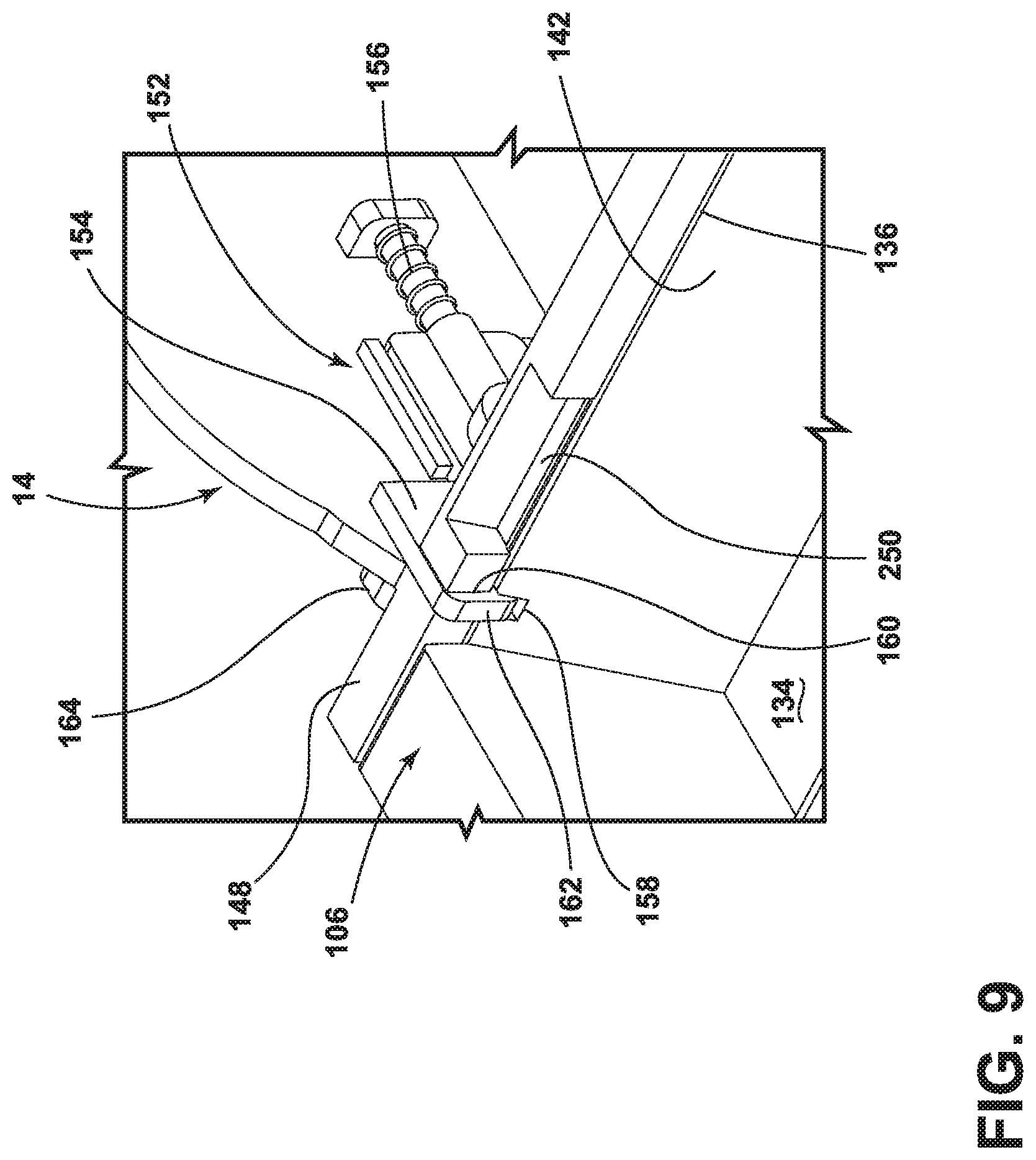
[0089] Referring to FIGS. 7-9, optionally, the sweeper 10 can include a collection cup latch 152 for securing the collection cup 106 to the base 14. The collection cup latch 152 can be configured to releasably lock the collection cup 106 on the base 14 so that that a user must actuate the latch 152 before removing the collection cup 106 from the base 14. Alternatively, collection cup latch 152 can be configured to releasably latch or retain, but not lock, the collection cup 106 on the base 14, such that a user can conveniently apply sufficient force to the collection cup 106 itself to pull the collection cup 106 off the base 14.
[0090] In one embodiment, the collection cup latch 152 can comprise a latch body 154 biased by a spring 156 to a latched or locked position shown in FIG. 9. A slot 158 formed through a wall of the collection cup 106, such as the rear wall 142, is in register with a slot 160 formed through the pocket 148 when the collection cup 106 is fully inserted into the pocket 148. A latching end 162 of the latch body 154 is biased toward the aligned slots 158, 160 by the spring 156.
[0091] The collection cup latch 152 can further comprise a user-engageable collection cup release button 164 operably coupled with the latch body 154. The latch body 154 can be disposed on an inside of the base 14, with the release button 164 on the exterior of the base 14, such as on the lateral side 128 of the base housing 104. The latch body 154 can be mounted for linear sliding movement within the base 14, or can move otherwise within the base 14, to move the latching end 162 out of the aligned slots 158, 160. Upon application a sufficient force on the release button 164 to overcome the force of the spring 156, the latch body 154 slides or otherwise moves away from the collection cup 106, moving the latching end 162 out of the aligned slots 158, 160, and freeing the collection cup 106 for removal from the base 14.
[0092] A handle 166 can be provided on the collection cup 106 to facilitate the removal of the collection cup 106 from the base 14 for emptying. In the illustrated embodiment, the handle 166 can be provided on the lateral side wall 146 of the collection cup 106. Conveniently, the handle 166 can be provided on the same side as the release button 164.
[0093] Referring to FIG. 5, in one embodiment, the removable cover 110 can be coupled to the forward portion of the base housing 104. The cover 110 can be removable from the base housing 104 without the use of tools. At least one cover latch 168 can be provided to releasably secure the cover 110 on the base housing 104, as described in further detail below. When secured on the base housing 104, the cover 110 can define at least a portion of the brush chamber 118 which partially encloses the brushroll 108. Additionally or alternatively, the cover 110 can define at least a portion of the collection chamber 134 when the collection cup 106 is installed on the base 14. In the illustrated embodiment, the cover 110 includes a curved forward end 170 which can wrap around and in front of the brushroll 108 to define the brush chamber 118 and a rearward end 172 which can extend over the collection chamber 134 to cover the entrance opening 136 of the collection cup 106.
[0094] The forward end 170 of the cover 110 can comprise a lower edge 174 defining a front opening 176 on the base 14. The lower edge 174 is spaced from the surface to be cleaned, such that a portion of the brushroll 108 is exposed from the front of the base 14 in addition to being exposed from the bottom of the base 14. The front opening 176 allows the lower edge 174 to move over larger dirt on the surface to be cleaned, and prevents the base 14 from plowing larger dirt in front of the base 14 on forward strokes of the sweeper 10. Larger dirt instead moves through the front opening 176 and is swept up by the brushroll 108. In one non-limiting example, the height of the front opening 176, i.e. the distance between the floor surface F and the lower edge 174 can be >0 mm and .ltoreq.the length of the microfibers of a microfiber material 220 covering the brushroll 108. In one embodiment, the length of the microfibers of a microfiber material 220 can be .ltoreq.16 mm, alternatively .ltoreq.13 mm, alternatively 11-13 mm, inclusive.
[0095] By removing the cover 110, the brushroll 108, brush chamber 118, and/or collection cup 106 can be easily accessed for cleaning or maintenance of the sweeper 10. In embodiments where the cover 110 defines the forward enclosure with the bottom housing 130, removing the cover 110 can provide access to the forward enclosure from above, so that a user does not have to turn the sweeper 10 over, or even move it from its normal operational position with the base 14 on the surface to be cleaned.
[0096] The cover 110 can comprise a hand grip, such as a carry handle 178, which can be used to lift the cover 110 away from the base housing 104. The sweeper 10 can be configured with sufficient clearance between carry handle 178 on the cover 110 and the yoke 34 of the joint assembly 32 so that the cover 110 can be lifted away from the base 14 by the carry handle 178 regardless of the rotational orientation of the upright body 12 relative to the base 14.
[0097] The cover 110 be at least partially formed from a translucent or transparent material, such that an interior space of the base 14 is visible to the user through the cover 110. Optionally, one or both of the brushroll 108 and the collection chamber 134 defined by the collection cup 106 can be at least partially visible to a user through the cover 110. This can allow the user to view the brushroll 108 and ascertain of the brushroll 108 needs cleaning, and/or to view the dirt collected in the collection chamber 134 to ascertain if the collection cup 106 needs emptying. As shown, the cover 110 can be molded from a translucent or transparent material using plastic injection molding. Alternatively, the cover 110 can be formed with one or more viewing windows in register with one or both of the brushroll 108 and the collection chamber 134 defined by the collection cup 106, with the viewing windows being formed from a translucent or transparent material.
[0098] In the embodiment shown herein, the collection cup 106 can be removed from the base 14 for emptying, without removing the cover 110. Alternatively, the collection cup 106 can be coupled with or otherwise combined with the cover 110 such that removing the cover 110 also removes the collection cup 106 for easy cleanout of both the brush chamber 118 and the collection cup 106 at the same time.
[0099] Optionally, the brushroll 108 can be configured to be removed by the user from the base 14, such as for cleaning and/or drying the brushroll 108. The brushroll 108 can be removably mounted in the brush chamber 118 by a brushroll latch 180 which is coupled with the brushroll 108. Accordingly, the cover 110 may be removed from the base housing 104 prior to removing the brushroll 108. The brushroll latch 180 can be inaccessible with the cover 110 on the housing 104, and accessible with the cover 110 removed from the housing 104. Once the cover 110 is removed, the brush chamber 118 and latch 180 can be accessed from above, so that a user does not have to turn the sweeper 10 over, or even move it from its normal operational position with the base 14 on the surface to be cleaned to remove the brushroll 108 from the brush chamber 118. In other embodiments, the brushroll 108 and latch 180 can be configured such that prior removal of the cover 110 is not required.
[0100] The brushroll latch 180 can be received by a mating component on the base housing 104. The mating component can be provided at one of the lateral sides 126, 128 of the base 14. In one embodiment, the base housing 104 can include spaced lateral sidewalls 182, 184 which define the brush chamber 118 therebetween. The mating component can be a cradle 186 provided on an inner surface of one of the lateral sidewalls 184. The brushroll latch 180 can be provided on one end of the brushroll 108 and received within the cradle 186 to mount the brushroll 108 within the brush chamber 118. The opposite end of the brushroll 108 can have a splined drive connection 188 with a transmission for driving the brushroll 108, as described in further detail below.
[0101] Referring to FIG. 10, the collection system can further include a motor 190 drivingly connected to the brushroll 108, as described below. The sweeper 10 can be cordless or battery powered. In the illustrated embodiment, a rechargeable battery 194 (e.g. a battery pack or a plurality of battery cells) is provided for cordless operation. In one example, the battery 194 can be a lithium ion battery. In another exemplary arrangement, the battery 194 can comprise a user replaceable battery. In an alternative embodiment, the sweeper 10 can have a power cord configured to be plugged into a household outlet for powering the electronic components of the sweeper 10.
[0102] The motor 190 can be adapted to drive the brushroll 108 at a speed sufficient to mechanically propel dirt and liquid swept up and absorbed by the brushroll 108 into the collection cup. In one embodiment, a speed of 500 RPM or greater is sufficient such that at least some of the dirt and/or liquid swept up by the brushroll 108 is thrown by centrifugal force into the collection cup during rotation of the brushroll 108 by the motor 190. Alternatively, the motor 190 can be adapted to drive the brushroll 108 at 1000 RPM or greater, alternatively at about 2000 RPM.
[0103] The sweeper 10 can further include a controller 196 operably coupled with the various function systems of the sweeper 10 for controlling its operation, such as being operably coupled with the brush motor 190 to provide brush motor control and the battery 194 for controlling a battery charging operation. The controller 196 can be a microcontroller unit (MCU) that contains at least one central processing unit (CPU). The controller 196 can be provided at various locations on the sweeper 10, and in the illustrated embodiment is located in the base 14, within the base housing 104. Alternatively, the controller 196 can be provided on the upright body 12, such as within the frame 18.
[0104] The sweeper 10 can further include at least one status indicator 198, such as an LED, which can communicate status information to the user. Such status information can include a power status, i.e. whether the sweeper 10 is powered on or off, or a battery status, i.e. whether the battery 194 is currently charging and/or the battery charge level. As shown herein, the status indicator 198 can be provided on the base 14 is visible to a user from the exterior of the sweeper 10. Alternatively, the status indicator 198 can be provided on the upright body 12, such as on the handle 16 or frame 18.
[0105] The battery 194 can be provided at various locations on the sweeper 10, such as in the base 14 or on the upright body 12, such as within the frame 18. In the illustrated embodiment, the battery 194 is mounted within the base 14 and is electrically connected to the brush motor 190. In particular, the battery 194 can be located within a battery compartment 200 located on or within the base 14, which can protect and retain the battery 194 on the sweeper 10. Optionally, the battery compartment 200 can be formed within the rear enclosure defined by the bottom and top housings 130, 132 (FIG. 5), which can also contain the brush motor 190 and the controller 196. Vents 202 can be provided in the rear enclosure, such as in the bottom housing 130 as shown in the illustrated embodiment, for cooling the motor 190 and the battery 194.
[0106] As shown, the battery compartment 200 can be located between the rear wheels 114 on the base 14. Optionally, the collection cup 106 can be positioned between the brushroll 108 and the battery 194, i.e. between the brush chamber 118 and the battery 194. In an alternative embodiment, the battery 194 and battery compartment 200 can be provided on the upright body 12. The brush motor 190 can be positioned between the battery 194 and the collection cup 106, although other locations are possible.
[0107] Referring additionally to FIG. 7, the motor 190 can be selectively energized by a brush power switch 192. The brush power switch 192 can be located on the base 14, although other locations are possible. With the brush power switch 192 located on the base 14, the switch 192 can conveniently be actuated by a user's foot to turn the motor 190 on and off. Regardless of its location, the brush power switch 192 can be operated independently of the trigger 24 (FIG. 2) so that cleaning fluid can be dispensed when the brushroll 108 is rotating for simultaneous wet mopping and sweeping, the brushroll 108 can be turned off while still dispensing cleaning fluid via the trigger for a wet mopping-only mode, or the brushroll 108 can be turned on while not dispensing cleaning fluid for a dry sweeping-only mode.
[0108] In embodiments where the sweeper 10 has a rechargeable battery 194, an appropriate charger can be provided with the sweeper 10. In one embodiment, the sweeper 10 can have a USB charging port 204 that can be used to charge the battery 194. A USB charging cable (not shown) can be provided for plugging the sweeper 10 into a household outlet. As shown herein, the USB charging port 204 can be provided on the base 14 and is accessible to a user from the exterior of the sweeper 10. Alternatively, the USB charging port 204 can be provided on the upright body 12, such as on the handle 16 or frame 18. In an alternative embodiment, the sweeper 10 can have charging contacts on the base 14, and a docking station (not shown) can be provided for receiving the sweeper 10 for recharging the battery 194 can be provided.
[0109] Referring to FIG. 10, the brushroll 108 can be operably coupled to and driven by a drive assembly including the motor 190 in the base 14. The drive coupling or transmission between the brushroll 108 and the motor 190 can comprise one or more belts, gears, shafts, pulleys or combinations thereof. One example of a transmission for the brushroll 108 is shown in FIG. 10. The transmission connects the brush motor 190 to the brushroll 108 for transmitting rotational motion of a shaft (not shown) of the brush motor 190 to the brushroll 108. The transmission can include a belt 206, a motor pulley 208 coupled with the motor 190 and a brushroll pulley 210 coupled with brushroll 108, with the belt 206 coupling the motor pulley 208 with the brushroll pulley 210. The transmission can further include a drive head 212 keyed to or otherwise fixed with the brushroll pulley 210. The drive head 212 can couple with the splined drive connection 188 of the brushroll 108 and can be provided at the lateral sidewall 182 opposite the cradle 186. The motor pulley 208 can be keyed to or otherwise fixed with the shaft of the motor 190. It is noted that in FIG. 10, a portion of the base 14 has been removed in order to view the transmission and an optional drive housing 214 for the transmission; particularly, the cover 110 and top housing 132 have been removed. The drive housing 214 can be formed with or otherwise coupled to the lateral sidewall 182 on the transmission side. It is noted that the collection cup 106 slides through the opposite lateral sidewall 184, i.e. the non-transmission or non-belt side.
[0110] One embodiment of the brushroll 108 for the sweeper 10 is shown in FIG. 10. In the present example, brushroll 108 can be a hybrid brushroll suitable for wet mopping or dry sweeping. In one embodiment, the brushroll 108 comprises a dowel 216, a plurality of bristles 218 extending from the dowel 216, and microfiber material 220 provided on the dowel 216 and arranged between the bristles 218. One example of a suitable hybrid brushroll is disclosed in U.S. Pat. No. 10,092,155, which is incorporated above. The bristles 218 can be arranged in a plurality of tufts or in a unitary strip. Dowel 216 can be constructed of a polymeric material such as acrylonitrile butadiene styrene (ABS), polypropylene or styrene, or any other suitable material such as plastic, wood, or metal. Bristles 218 can be tufted or unitary bristle strips and constructed of nylon, or any other suitable synthetic or natural fiber. The microfiber material 220 can be constructed of polyester, polyamides, or a conjugation of materials including polypropylene or any other suitable material known in the art from which to construct microfiber. The microfiber of the microfiber material 220 can be a synthetic fiber that is one denier or less, and/or that has a diameter of less than 10 micrometers.
[0111] Other embodiments of the brushroll 108 are possible. For example, the brushroll 108 can comprise tufted bristles as the only sweeping medium. Alternatively, the brushroll 108 can comprise a sweeping medium made of a soft and compressible material, such as microfiber material. For example, the brushroll 108 can comprise the microfiber material 220 as the only sweeping medium. In still other embodiments, the brushroll 108 can comprise nylon fiber, foam, elastomeric blades and paddles, or any other sweeping medium suitable for mechanically propelling dirt and liquid into the collection cup 106. Additionally, while a horizontally-rotating brushroll 108 is shown herein, in some embodiments, dual horizontally-rotating brushrolls, one or more vertically-rotating brushrolls can be provided on the sweeper 10.
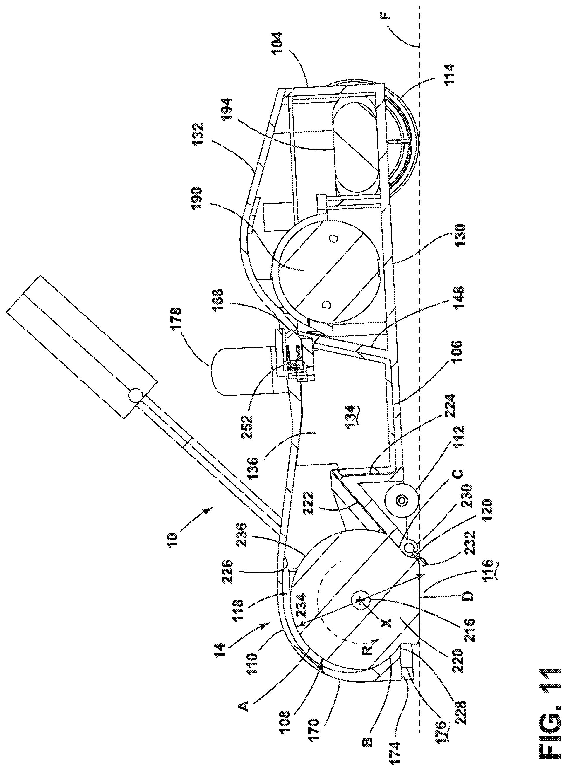
[0112] Referring to FIG. 11, as disclosed above, the brushroll 108 can be provided adjacent to the inlet opening 116 with a portion of the brushroll 108 projecting through the inlet opening 116 to contact the surface below the base 14. The brushroll 108 rotates to sweep the surface to be cleaned so that the dirt and liquid swept up by the brushroll 108 is mechanically propelled into the collection cup 106. A ramp 222 can be provided at a rear portion of the brush chamber 118 for guiding dirt and liquid toward the entrance opening 136 into the collection chamber 106. Optionally, the ramp 222 itself can define part of the brush chamber 118, particularly a rear part of the brush chamber 118. The ramp 222 can extend from the rear side of the inlet opening 116 upwardly to the entrance opening 136. The ramp 222 can optionally form a portion of a divider 224 partitioning the brush chamber 118 off from the collection cup pocket 148 in the base 14, and can aid in trapping any dirt or liquid removed from the surface to be cleaned by the sweeper 10 in the collection cup 106. In at least some embodiments, the ramp 222 can have an angle with respect to the floor surface F of >0 degrees and .ltoreq.90 degrees.
[0113] In at least some embodiments of the brushroll 108, liquid swept up and absorbed by the rotating brushroll 108 can spin off the brushroll 108 and fly backwards into the collection cup 106. Some liquid may strike an upper inside surface 226 of the cover 110 before dropping into the collection cup 106. At least a portion of the upper inside surface 226 of the cover 110 can overlie at least a portion of the ramp 222. The upper inside surface 226 can advantageously be angled downwardly in a rearward direction or toward the collection cup 106 to encourage liquid to drop or flow into the collection cup 106. In at least some embodiments, the upper inside surface 226 can have an angle with respect to the floor surface F of .gtoreq.0 degrees (i.e. parallel to the floor surface F) and .ltoreq.45 degrees. Additionally, in embodiments where ramp 222 is present, some liquid spun off the brushroll 108 can fly along or above the ramp 222. Still further, in embodiments where the brushroll 108 comprises an absorbent material capable of absorbing liquid, such as microfiber material 220, some liquid can be absorbed by the brushroll 108. At least some of this absorbed liquid may be spun off the brushroll 108 and collected in the collection cup 106, and/or at least some of this absorbed liquid may be retained by the brushroll 108.
[0114] The cover 110 can include an interference edge 228, such as a rigid wiper, facing the brush chamber 118 and interfacing with the brushroll 108. The interference edge 228 can be a thin or narrow edge, such as a blade or scraper, and can be integrally formed with the cover. Alternatively, the interference edge 228 can be separately formed and coupled to the cover 110.
[0115] The interference edge 228 can be on the inside of the forward end 170. In the illustrated embodiment, the interference edge 228 comprises the rear-facing side of the lower edge 174 defining the front opening 176 on the base 14. Alternatively, the interference edge 228 can be provided separately form the lower edge 174 on the inside of the forward end 170, or elsewhere on the inside of the cover 110. The lower edge 174 or interference edge 228 can further define the leading edge of the inlet opening 116.
[0116] The interference edge 228 is configured to engage with a leading portion of the brushroll 108, as defined by the direction of rotation R of the brushroll 108 about brush rotational axis X. As the brushroll 108 rotates, the interference edge 228 can scrape excess liquid off the brushroll 108 and can help redistribute the liquid evenly along the length of the brushroll 108, which can help to reduce streaking on the surface to be cleaned.
[0117] The interference edge 228 can be rigid, i.e. stiff and non-flexible, so the edge 228 does not yield or flex by engagement with the brushroll 108. In one example, the interference edge 228, and optionally the cover 110, can be formed of rigid thermoplastic material, such as poly(methyl methacrylate) (PMMA), polycarbonate, or acrylonitrile butadiene styrene (ABS).
[0118] The squeegee 120 can be provided adjacent a trailing edge 230 of the inlet opening 116, behind the brushroll 108, in order to aid in dirt and liquid collection and is configured to contact the surface as the sweeper 10 moves across the surface to be cleaned. Particularly with respect to liquid on the surface to be cleaned, the squeegee 120 wipes residual liquid from the surface to be cleaned during a forward stroke or forward movement of the sweeper 10, so that it can be collected by the brushroll 108 on a backstroke or backward movement of the sweeper 10, thereby leaving a moisture and streak-free finish on the surface to be cleaned. As used herein, a stroke refers to movement of the sweeper 10 relative to the surface being cleaned in a single direction, from the perspective of a user positioned behind the sweeper 10.
[0119] The squeegee 120 can be an elongated blade that generally spans at least the width of the inlet opening 116, or can generally span the width of the base 14, and can be supported by the bottom housing 130. Optionally, the squeegee 120 can be angled forwardly to encourage the squeegee 120 to skim over liquid and small dirt on a backstroke of the sweeper 10. Alternatively, the squeegee 120 can be disposed generally orthogonal to the surface to be cleaned, or vertically. The squeegee 120 can comprise a smooth forward-facing surface and a rear surface with a plurality of nubs 232 on the end thereof as shown, or optionally comprise smooth front and rear surfaces. The nubs 232 can reduce the contact area of the squeegee 120 with the surface to be cleaned on a backstroke of the sweeper 10 to reduce the push force required to move the sweeper 10.
[0120] The squeegee 120 can be coupled with the trailing edge 230 of the inlet opening 116, and the trailing edge 230 can be configured to engage with a trailing portion of the brushroll 108, as defined by the direction of rotation R of the brushroll 108. The trailing edge 230 can further be defined by a lower end of the ramp 222. As the brushroll 108 rotates, the trailing edge 230 compresses a portion of the brushroll 108, and the brushroll 108 can remain compressed against the lower end of the ramp 222 a short distance before diverging from the ramp 222.
[0121] The squeegee 120 can be pliant, i.e. flexible or resilient, in order to bend readily according to the contour of the surface to be cleaned and/or the brushroll 108, yet remain undeformed by normal use of the sweeper 10. Optionally, the squeegee 120 can be formed of a resilient polymeric material, such as ethylene propylene diene monomer (EPDM) rubber, polyvinyl chloride (PVC), a rubber copolymer such as nitrile butadiene rubber, or any material known in the art of sufficient rigidity to remain substantially undeformed during normal use of the sweeper 10.
[0122] The brushroll 108 has an uncompressed diameter 234 that defines a circumference or outside surface 236 of the brushroll 108 in an uncompressed state. The brush chamber 118 can be configured with a brushroll clearance that varies radially relative to the brushroll rotational axis X. The brushroll clearance can vary from positive to negative values. At some points about the radius, the brush chamber 118 can have a positive clearance value, where the brush chamber 118 is spaced from the outside surface 236 of the brushroll 108 and the brushroll 108 is uncompressed. At other points, the brush chamber 118 can have a negative clearance value, where the brush chamber 118 interferes with the outside surface 236 of the brushroll 108 and the brushroll 108 is compressed. At yet other points, the brush chamber 118 can have a zero clearance value, where the brush chamber 118 just meets the outside surface 236 of the brushroll 108 but the brushroll 108 is uncompressed. Is it noted that in operation, the base 14 moves over the surface to be cleaned on wheels 112, 114.
[0123] An exemplary floor surface F is shown in FIG. 11 in phantom line. FIGS. 2, 5, and 10 show the brushroll 108 uncompressed, whereas in operation, the brushroll 108 may be compressed where it engages the floor surface F as shown in FIG. 11, and at other points as described in further detail below. In particular, the bottom portion of the brushroll 108 can compress flat against the floor surface F.
[0124] In the illustrated embodiment, where the brush chamber 118 is defined at least in part by the cover 110 and the ramp 222, the brushroll clearance at various points can vary to increase or decrease the compression of the brushroll 108 by the brush chamber 118 and increase or decrease the interference between the brush chamber 118, the brushroll 108, and the floor surface F, thereby balancing cleaning performance or efficacy of the sweeper 10 with battery life.
[0125] For example, in the embodiment shown in FIG. 11, the brushroll clearance at points A, B, C, and D are configured to balance cleaning performance with battery life. Optionally, one or more of the brushroll clearance at points A, B, C, and D can depend on the radius of the brushroll 108 and more particularly on the length of the microfibers of the microfiber material 220.
[0126] The brushroll clearance at point A, i.e. between the brushroll 108 and the curved forward end 170 of the cover 110 which can wrap around and in front of the brushroll 108, can have a zero clearance value, such that the inside surface of the forward end 170 just meets the outside surface 236 of the brushroll 108, and the brushroll 108 is uncompressed at point A. Alternatively, the brushroll clearance at point A can be in the range of -5 mm to +5 mm, or .gtoreq.-half the length of the microfibers of the microfiber material 220, i.e. the uncompressed diameter 234 of the brushroll 108 will be compressed by a distance equal to half the length of the microfibers of the microfiber material 220 at point A.
[0127] The brushroll clearance at point B, i.e. between the brushroll 108 and the interference edge 228 of the cover 110, can have a negative clearance value, such that the interference edge 228 interferes with the outside surface 236 of the brushroll 108 and the brushroll 108 is compressed at point B. In one non-limiting example, the brushroll clearance at point B can be -7 mm, i.e. the uncompressed diameter 234 of the brushroll 108 will be compressed by 7 mm at point B. Alternatively, the brushroll clearance at point B can be in the range of -7 mm to +2 mm, or .gtoreq.-the length of the microfibers of the microfiber material 220, i.e. the uncompressed diameter 234 of the brushroll 108 will be compressed by a distance equal to the length of the microfibers of the microfiber material 220 at point B.
[0128] The brushroll clearance at point C, i.e. between the brushroll 108 and the trailing edge 230 of the inlet opening 116, can have a negative clearance value, such that the trailing edge 230 of the inlet opening 116 interferes with the outside surface 236 of the brushroll 108 and the brushroll 108 is compressed at point C. In one non-limiting example, the brushroll clearance at point C can be -5 mm, i.e. the uncompressed diameter 234 of the brushroll 108 will be compressed by 5 mm at point C. Alternatively, the brushroll clearance at point C can be in the range of -5 mm to 0 mm, or .gtoreq.-the length of the microfibers of the microfiber material 220, i.e. the uncompressed diameter 234 of the brushroll 108 will be compressed by a distance equal to the length of the microfibers of the microfiber material 220 at point C.
[0129] The brushroll clearance at point D, i.e. between the brushroll 108 and the floor surface F, can have a negative clearance value, such that the floor surface F interferes with the outside surface 236 of the brushroll 108 and the brushroll 108 is compressed at point D. In one non-limiting example, the brushroll clearance at point D can be -8 mm, i.e. the uncompressed diameter 234 of the brushroll 108 will be compressed by 8 mm at point D. It is noted that the brushroll clearance at point D, i.e. between the brushroll 108 and the floor surface F, can be a function of the spatial relationship between the brushroll 108, the brush chamber 118, and the wheels 112, 114. Alternatively, the brushroll clearance at point D can be in the range of -8 mm to 0 mm, or .gtoreq.-the length of the microfibers of the microfiber material 220, i.e. the uncompressed diameter 234 of the brushroll 108 will be compressed by a distance equal to the length of the microfibers of the microfiber material 220 at point D.
[0130] FIG. 11 also shows the squeegee 120 unbent, whereas in operation, the squeegee 120 may be bent where it engages the floor surface F. On a forward stroke of the sweeper 10, the squeegee 120 can bend backward about the trailing edge 230, with the smooth forward-facing surface the squeegee 120 in contact with the floor surface F, and on a backstroke of the sweeper 10, the squeegee 120 can bend forward with the rear surface having the plurality of nubs 232 in contact with the floor surface F.
[0131] The at least one cover latch 168 can be provided to releasably secure the cover 110 on the base housing 104. The at least one cover latch 168 can be received in a latch catch 250 (see FIG. 10) provided on the base housing 104, and be biased by a spring 252 to a latched position. The at least one cover latch 168 can be configured to releasably latch or retain, but not lock, the cover 110 to the base housing 104, such that a user can conveniently apply sufficient force to the cover 110 itself, such as via the carry handle 178, to pull the cover 110 off the base housing 104. In one embodiment, the cover 110 can include a pair of cover latches 168, and the base housing 104 can have a corresponding pair of latch catches 250. More particularly, the latch catches 250 can be provided on the top housing 132 of the base housing 104.
[0132] A sweeper 10' according to a second embodiment of the invention is described with respect to FIGS. 12-14. Many of the components of the second embodiment are similar to the first embodiment, and like features are indicated with the same reference numeral bearing a prime (') symbol. Any one or combination of the previously described features, including transversely-slidable collection cup, hybrid brushroll, interference edge, squeegee, or brushroll chamber with varying brushroll clearances, can be incorporated into this embodiment of the invention.
[0133] In the second embodiment, the upright body 12' is swivelably mounted base 14' through a swivel joint 260. The swivel joint 260 can comprises a multi-axis Cardan joint as shown in the figures, but can alternatively comprise a ball joint to swivelably connect the base 14' to the upright body 12'. The swivel joint 260 is adapted to pivotally connect the base 14' to the upright body 12' and defines a first axis 262, which is generally perpendicular to the direction of travel of the sweeper 10. The upright body 12' can be pivoted from front-to-back with respect to the base 14' about axis 262. The swivel joint 260 further defines a second axis 264, which is generally parallel to the direction of travel of the sweeper 10, and about which the upright body 12' can be pivoted from side-to-side with respect to the base 14'. Accordingly, the swivel joint 260 is configured to permit the base 14' to swivel multi-axially with respect the upright body 12'. Wiring and/or conduits can optionally supply electricity and/or liquid (or other fluids) between the base 14' and the upright body 12', or vice versa, and can extend though the swivel joint 260.
[0134] The upright body 12' can pivot, via the swivel joint 260, to an upright or storage position, an example of which is shown in FIG. 12, in which the upright body 12' is oriented substantially upright relative to the surface to be cleaned and in which the sweeper 10' is self-supporting, i.e. the sweeper 10' can stand upright without being supported by something else. A locking mechanism (not shown) can be provided to lock the swivel joint 260 against movement about at least one of the axes 262, 264 of the swivel joint 260 in the storage position, which can allows the sweeper 10' to be self-supporting. From the storage position, the upright body 12' can pivot, via the swivel joint 260 to a reclined or use position (not shown), in which the upright body 12' is pivoted rearwardly relative to the base 14' to form an acute angle with the surface to be cleaned. In this position, a user can partially support the apparatus by holding the hand grip 22'.
[0135] In one embodiment, the base 14' of the sweeper 10' can comprise a single rear wheel 266 disposed at a rear of the base 14'. The use of a single rear wheel 266 rather than a pair of wheels can reduce the overall contact area of the sweeper 10' with the surface to be cleaned, thereby reducing the occurrence and appearance of streaks caused by wheels rolling on a cleaned wet surface. A pair of forward wheels (not shown) can optionally be disposed on the base 14' forwardly of the single rear wheel 266. The rear wheel 266 can be centered below the upright body 12', and optionally below the swivel joint 260 coupling the upright body 12' to the base 14'. More particularly, the rear wheel 266 can be rotatably mounted to a yoke 268 of the swivel joint 260, with the rotational axis of the wheel 266 coincident with the first axis 262 about which the upright body 12' can be pivoted from front-to-back with respect to the base 14'. The yoke 268 is pivotally connected to the base 14' on lateral sides thereof opposing the wheel 266. The yoke 268 is further fixed with the upright body 12', either directly or via an extension (not shown) on a lower end of the upright body 12', which can particularly extend from a lower end of the frame 18'.
[0136] In the second embodiment, the handle 16' is pivotal with respect to the frame 18' via a handle pivot or coupler 270 to rotate or fold down toward the frame 18'. In particular, the handle 16' can pivot between an extended position, shown in FIG. 12, to a folded position (not shown). One example of a suitable handle pivot or coupler is disclosed in U.S. Pat. No. 9,924,842, issued Mar. 27, 2018, which is incorporated herein by reference in its entirety.
[0137] The sweeper 10' can include at least one user interface 272, 274 through which a user can interact with the sweeper 10'. The user interface 272, 274 can enable operation and control of the sweeper 10' from the user's end, and can also provide feedback information from the sweeper 10' to the user. The user interface 272, 274 can be electrically coupled with electrical components, including, but not limited to, circuitry electrically connected to various components of the fluid delivery and collection systems of the sweeper 10', as described in further detail below.
[0138] In the illustrated embodiment, the sweeper 10' includes a human-machine interface (HMI) 272 having one or more input controls, such as but not limited to buttons, triggers, toggles, keys, switches, or the like, operably connected to systems in the sweeper 10' to affect and control its operation. The sweeper 10' also includes a status user interface (SUI) 274 which communicates a condition or status of the sweeper 10' to the user. The SUI 274 can communicate visually and/or audibly, and can optionally include one or more input controls. The HMI 272 and the SUI 274 can be provided as separate interfaces or can be integrated with each other, such as in a composite use interface, graphical user interface, or multimedia user interface. As shown, the HMI 272 can be provided at a front side of the hand grip 22', with the trigger 24' provided on a rear side of the hand grip 22', opposite the HMI 272, and the SUI 274 can be provided on a front side of the frame 18', below the handle 16' and above the base 14', and optionally above the supply tank 20', which can optionally be provided on a rear side of the frame 18' as shown. In other embodiments, the HMI 272 and SUI 274 can be provided elsewhere on the sweeper 10'. One example of a suitable HMI and/or SUI is disclosed in U.S. Provisional Application No. 62/747,922, filed Oct. 19, 2018, now PCT/US2019/057196 filed Oct. 21, 2019, which is incorporated herein by reference in its entirety. Either user interface 272, 274 can comprise a proximity-triggered interface, as described in the '922 application.
[0139] The HMI 272 can include one or more input controls 276 in register with a printed circuit board (PCB, not shown) within the hand grip 22'. In one embodiment, one input control 276 is a power input control which controls the supply of power to one or more electrical components of the sweeper 10', as explained in further detail below, one of which may be the SUI 274. The input control 276 can comprise a button, trigger, toggle, key, switch, or the like, or any combination thereof. In one example, the input control 276 can comprise a capacitive button.
[0140] The SUI 274 can include a display 278, such as, but not limited to, an LED matrix display or a touchscreen. In one embodiment, the display 278 can include multiple status indicators which can display various detailed apparatus status information, such as, but not limited to, battery status, Wi-Fi connection status, cleaning fluid level in the supply tank, dirt/liquid level in the collection cup, filter status, floor type, self-cleaning, or any number of other status information. The status indicators can be a visual indicator, and may include any of a variety of lights, such as LEDs, textual displays, graphical displays, or any variety of known status indicators.
[0141] The SUI 274 can include at least one input control 280, which can be adjacent the display 278 or provided on the display 278. The input control 280 can comprise a button, trigger, toggle, key, switch, or the like, or any combination thereof. In one example, the input control 280 can comprise a capacitive button. In one example, the input control 280 can comprise a self-cleaning mode input control which initiates a self-cleaning mode of operation. Examples of self-cleaning cycles are disclosed in U.S. Patent Application Publication No. 2018/0344112, filed May 31, 2018, which is incorporated herein by reference in its entirety.
[0142] FIG. 14 is a schematic control diagram for the sweeper 10'. The controller 196' of the sweeper 10' can be operably coupled with the various function systems of the sweeper 10' for controlling its operation. In the illustrated embodiment, the controller 196' is operably coupled with the HMI 272 for receiving inputs from a user and with the SUI 274 for providing one or more indicia about the status of the sweeper 10'. In one embodiment, the controller 196' can comprise a microcontroller unit (MCU) that contains at least one central processing unit (CPU). The controller 196' can be provided at various locations on the sweeper 10', such as being integrated with the SUI 274. Alternatively, the controller 196' can be integrated with the HMI 272, or can be separate from both the HMI 272 and SUI 274.
[0143] As discussed above, the power input control 276 which controls the supply of power to one or more electrical components of the sweeper 10', and in the illustrated embodiment controls the supply of power to one or more of the SUI 274, the pump 52', and/or the brush motor 190'. Electrical components of the sweeper 10', including the pump 52' for the flow control system and/or the brush motor 190' for the brushroll 108', can be electrically coupled to a power source such as battery 194' or a power cord plugged into a household outlet. In the illustrated embodiment, the pump 52' can be an electrically-actuated pump, such as, but not limited to, a solenoid pump having a single, dual, or variable speed. Alternatively, the pump 52' can be a mechanically actuated by the trigger 24' as described above for the first embodiment.
[0144] The battery 194' can be located within a battery housing 282 located on the upright body 12' or base 14' of the sweeper 10', which can protect and retain the battery 194' on the sweeper 10'. In the illustrated embodiment, the battery housing 282 is provided on a lower end of the frame 18' of the upright body 12'.
[0145] A sweeper 10'' according to a third embodiment of the invention is described with respect to FIG. 15. Many of the components of the third embodiment are similar to the first embodiment, and like features are indicated with the same reference numeral bearing a double prime ('') symbol. Any one or combination of the previously described features, including transversely-slidable collection cup, hybrid brushroll, interference edge, squeegee, or brushroll chamber with varying brushroll clearances, can be incorporated into this embodiment of the invention.
[0146] In the third embodiment, the sweeper 10'' has a battery in the form of a rechargeable battery pack 290 that is removable from the base 14''. The battery pack 290 has a USB charging port 292 that can be used to charge the battery. A USB charging cable (not shown) can be provided for plugging the sweeper 10'' into a household outlet.
[0147] The battery pack 290 can be removable from a battery compartment 294 located on or within the base 14'', which can protect and retain the battery pack 290 on the sweeper 10''. Optionally, the battery compartment 294 can be formed as an open-topped pocket or cavity on the base housing 104''. The battery compartment 294 can be rearward of the cover 110'' so that the battery pack 290 can be removed without having to remove the cover 110''.
[0148] As shown herein, the USB charging port 292 can be accessible to a user from the exterior of the sweeper 10'' for attachment of the USB charging cable. The battery compartment 294 can have an aperture 296 in register with the USB charging port 292 when. In the illustrated embodiment, the aperture 296 is provided in the base housing 104'', and more particularly on the rear side of the bottom housing 130'', although other locations are possible.
[0149] A sweeper 300 according to a fourth embodiment of the invention is described with respect to FIGS. 16-17. The sweeper 300 of the third embodiment is an autonomous or robotic sweeper, and mounts the components of the various functional systems of the sweeper 300 in an autonomously moveable unit or housing 302, including a fluid delivery system, a collection system, and an autonomous drive system. Any of the previously described features of fluid delivery and collection system in the first and second embodiments, including transversely-slidable collection cup, hybrid brushroll, interference edge, squeegee, or brushroll chamber with varying brushroll clearances, can be incorporated into this embodiment of the invention.
[0150] The sweeper 300 can include at least one user interface 304 through which a user can interact with the sweeper 300. The interface 304 can enable operation and control of the sweeper 300 from the user's end, and can also provide feedback information from the sweeper 300 to the user. The user interface 304 can be electrically coupled with electrical components, including, but not limited to, circuitry electrically connected to various components of the fluid delivery and collection systems of the sweeper 300. The user interface 304 can have one or more input controls, such as but not limited to buttons, triggers, toggles, keys, switches, or the like, operably connected to systems in the sweeper 300 to affect and control its operation. In one example, a power button 306 controls the supply of power to one or more electrical components of the sweeper 300. The user interface 304 communicate visually and/or audibly. Additionally or alternatively, a user interface for the sweeper 300 can be provided as an application executed on a smartphone for controlling one or more functions of the sweeper 300.
[0151] The sweeper 300 can further include a controller 308 operably coupled with the various function systems of the sweeper 300 for controlling its operation. The controller 308 can be a microcontroller unit (MCU) that contains at least one central processing unit (CPU). The controller 308 can be operably coupled with the user interface 304 for receiving inputs from a user and for providing one or more indicia about the status of the sweeper 300 to the user, and can further be operably coupled with at least one sensor 310 for receiving input about the environment and can use the sensor input to control the operation of the sweeper 300. Some non-limiting examples of sensors 310 include distance sensors for determining the distance of the sweeper relative to obstacles, cliff sensors that provide distance feedback so that the sweeper can avoid excessive drops such as stairwells or ledges, bump sensors for determining front or side impacts to the sweeper, wall following sensors that provide distance feedback so that the sweeper can follow near a wall without contacting the wall, accelerometers to sense linear, rotational and magnetic field acceleration, lift-up sensors which detect when the sweeper is lifted off the surface to be cleaned, such as when the user picks up the sweeper, and floor condition sensors, such as an infrared dirt sensor, a stain sensor, an odor sensor, and/or a wet mess sensor, for detecting a condition of the surface to be cleaned.
[0152] The autonomous sweeper 300 can include a power supply on-board the housing 302, which can be a rechargeable battery 312 (e.g. a battery pack or a plurality of battery cells, such as a lithium ion battery or battery pack.
[0153] The autonomous drive system is configured for autonomously moving the sweeper 300 over the surface to be cleaned. The sweeper 300 can be configured to move randomly about a surface while cleaning the floor surface, using input from various sensors to change direction or adjust its course as needed to avoid obstacles, or can include a navigation/mapping system for guiding the movement of the sweeper 300 over the surface to be cleaned. In one embodiment, the sweeper 300 includes a navigation and path planning system that is operably coupled with the drive system. The system builds and stores a map of the environment in which the sweeper 300 is used, and plans paths to methodically clean the available area. An artificial barrier system (not shown) can optionally be provided with the sweeper 300 for containing the sweeper 300 within a user-determined boundary.
[0154] The drive system can include drive wheels 314 for driving the autonomous sweeper 300 across a surface to be cleaned. The drive wheels 314 can be operated by a common drive motor or individual drive motors (not shown) coupled with the drive wheels 314 by a transmission, which may include a gear train assembly or another suitable transmission. The drive system can receive inputs from the controller 308 for driving the sweeper 300 across a floor, based on inputs from the navigation/mapping system. The drive wheels 314 can be driven in a forward or reverse direction in order to move the housing 302 forwardly or rearwardly, and can be operated simultaneously or individually in order to turn the housing 302 in a desired direction. The controller 308 can receive input from the navigation/mapping system for directing the drive system to move the sweeper 300 over the surface to be cleaned. The navigation/mapping system can include a memory that stores maps for navigation and inputs from various sensors, which is used to guide the movement of the sweeper 300.
[0155] The fluid delivery system can include a supply tank 318 for storing a supply of cleaning fluid and at least one fluid distributor 320 in fluid communication with the supply tank 318 for depositing a cleaning fluid onto the surface. The cleaning fluid can be a liquid such as water or a cleaning solution specifically formulated for hard surface cleaning. The fluid distributor 320 can be one or more spray nozzles provided on the housing 302 of the sweeper 300. Alternatively, the fluid distributor 320 can be a manifold having multiple outlets. A fluid delivery pump 322 is provided in the fluid pathway between the supply tank 318 and the fluid distributor 320 to control the flow of fluid to the fluid distributor 320. Various combinations of optional components can be incorporated into the fluid delivery system as is commonly known in the art, such as a heater for heating the cleaning fluid before it is applied to the surface or one more fluid control and mixing valves.
[0156] The fluid distributor 320 can be positioned to dispense cleaning fluid onto the surface to be cleaned, either directly onto the surface to be cleaned, such as by having an outlet of the fluid distributor 320 positioned in opposition to the surface, or indirectly onto the surface to be cleaned, such as by having an outlet of the fluid distributor 320 positioned to dispense onto a an agitator such as a brushroll 326. In one embodiment, the fluid distributor 320 is positioned to dispense cleaning fluid onto the surface to be cleaned underneath the housing 302.
[0157] Alternatively, the fluid distributor 320 can dispense cleaning fluid directly onto a surface to be cleaned outwardly from the housing 302 so that the user can see exactly where cleaning fluid is being dispensed. For example, the fluid distributor 320 can dispense cleaning fluid forwardly, rearwardly, laterally, or anywhere outward from the housing 302 of the sweeper 300. As shown herein, the fluid distributor 320 is positioned on the exterior of the housing 302 to spray cleaning fluid forwardly of the sweeper 300, such that both the fluid distributor 320 and the cleaning fluid it dispenses is easily viewed during operation of the sweeper 300.
[0158] The autonomous sweeper 300 can include a brush chamber 324 at a front of the housing 302 in which the brushroll 326 is mounted. As used herein for the sweeper 300, "front" or "forward" and variations thereof are defined relative to the direction of forward travel of the autonomous sweeper 300, unless otherwise specified. The brushroll 326 is mounted for rotation about a substantially horizontal axis, relative to the surface over which the housing 302 moves. In one embodiment, the brushroll 326 can be a hybrid brushroll as described above with reference to FIG. 10, although the autonomous sweeper 300 can include any embodiment of brushroll otherwise described herein. A brush motor 328 can be provided within the housing 302 to drive the brushroll 326. A drive transmission (not shown), for example including a belt, operably connects a motor shaft of the motor 328 with the brushroll 326 for transmitting rotational motion of the motor shaft to the brushroll 326. Alternatively, the brushroll 326 can be driven mechanically by the autonomous movement of the sweeper 300.
[0159] The collection system can include an inlet opening 330, a collection cup 332 for collecting liquid and dirt from the surface for later disposal, and the agitator or brushroll 326. The inlet opening 330 can be provided on a lower side 334 of the housing 302 adapted to be adjacent the surface to be cleaned as the housing 302 moves autonomously across a surface. The brushroll 326 can be provided adjacent to the inlet opening 330 for sweeping the surface to be cleaned so that the dirt and liquid swept up by the brushroll 326 is mechanically propelled into the collection cup 332.
[0160] In one embodiment, a squeegee 336 can be provided adjacent a trailing edge 338 of the inlet opening 330, behind the brushroll 326, in order to aid in dirt and liquid collection and is configured to contact the surface as the housing 302 moves across the surface to be cleaned. The squeegee 336 can be an elongated blade that generally spans at least the width of the inlet opening 330, or can generally span the width of the housing 302, and can be similar to the squeegee as described above with reference to FIG. 11, although the autonomous sweeper 300 can include any embodiment of squeegee or wiper blade otherwise described herein.
[0161] Optionally, a bottom housing or sole plate 340 can at least partially retain the brushroll 326 in the brush chamber 324, and can include the inlet opening 330 of the collection system. The squeegee 336 can be supported by the bottom housing or sole plate 340.
[0162] The brushroll 326 can be mounted at the front of the autonomous sweeper 300, whereas brushrolls on most autonomous surface cleaners are mounted near middle of the unit, and hidden under an opaque plastic housing. The housing 302 of the illustrated sweeper 300 can be configured to accommodate the brushroll 326 in the forward location, such as by having an overall "D-shape" when viewed from above, with the housing 302 having a straight front edge 342 and a rounded rear edge 344. The housing 302 can further include lateral sides 346, 348 that generally extend between the straight front edge 342 and the rounded rear edge 344, and can be straight, rounded, or otherwise contoured. As described in more detail below, in one embodiment, the collection cup 332 can be removable though one of the lateral sides 346, 348 of the housing 302.
[0163] A removable cover 350 can be provided on the housing 302 which encloses one or both of the collection cup 332 and the brushroll 326 or other agitator. The cover 350 can be releasably secured to the housing 302 by at least one cover latch 352, which can be substantially similar to the cover latch 168 described above with reference to FIG. 11, although the autonomous sweeper 300 can include any embodiment of cover latch otherwise described herein. The cover 350 be at least partially formed from a translucent or transparent material, such that an interior space of the sweeper 300, such as one or both of the brushroll 326 and a collection chamber 354 defined by the collection cup 332, is visible to the user through the cover 350, as described above with reference to FIG. 5.
[0164] When secured on the housing 302, the cover 350 can define at least a portion of the brush chamber 324 which partially encloses the brushroll 326. Additionally or alternatively, the cover 350 can define at least a portion of the collection chamber 354 when the collection cup 332 is installed on the housing 302. In the illustrated embodiment, the cover 350 includes a curved forward end 356 which can wrap around and in front of the brushroll 326 to define the brush chamber 324 and a rearward end 358 which can extend over the collection chamber 354 to cover the open top of the collection cup 332. The cover 350 can define at least the straight front edge 342 of the housing 302; more particularly, the curved forward end 356 of the cover 350 can define at least the straight front edge 342 of the housing 302.
[0165] Optionally, the brushroll 326 can be configured to be removed by the user from the housing 302, such as for cleaning and/or drying the brushroll 326. The brushroll 326 can be removably mounted in the brush chamber 324 by a brushroll latch (not shown), which can be substantially similar to the brushroll latch 180 described above with reference to FIG. 5, although the autonomous sweeper 300 can include any embodiment of brushroll latch otherwise described herein. The cover 350 can be removed to expose the brushroll 326, which can then be removed from above as previously described for FIG. 5.
[0166] The collection cup 332 can any type of collection bin or tank suitable for the purposes described herein, including the collection of dirt and liquid. The collection cup 332 has a generally open top that defines an entrance opening 360 into the collection chamber 354 and which is in fluid communication with the brush chamber 324. Dirt and liquid that is swept up by the brushroll 326 can be propelled through the entrance opening 360 into the collection cup 332. In the illustrated embodiment, the collection cup 332 is substantially similar to the collection cup 106 described above with reference to FIG. 5, although the autonomous sweeper 300 can include any embodiment of collection cup otherwise described herein.
[0167] The collection cup 332 is removable from the housing 302 for emptying. The housing 302 can include a collection cup receiver, such as a collection cup pocket 362, for receiving the collection cup 332. The collection cup 332 can slide into the pocket 362 to install the collection cup 332 on the housing 302 and can slide out of the pocket 362 to remove the collection cup 332 from the housing 302.
[0168] In one embodiment, the collection cup 332 can be removed through the lateral side 346 of the housing 302 for emptying. The collection cup 332 can slide out of the housing 302 transversely to remove the collection cup 332 from the housing 302. In the embodiment illustrated herein with the pocket 362, the pocket 362 can comprise a pocket opening 364 at the lateral side 346 of the housing 302 through which the collection cup 332 can traversely slide. Optionally, the sweeper 300 can include a collection cup latch for securing the collection cup 332 to the housing 302 which can be substantially similar to the collection cup latch 152 described above with reference to FIGS. 7-9, although the autonomous sweeper 300 can include any embodiment of collection cup latch otherwise described herein.
[0169] In the embodiment shown herein, the collection cup 332 can be removed from the housing 302 for emptying, without removing the cover 350. Alternatively, the collection cup 332 can be coupled with or otherwise combined with the cover 350 such that removing the cover 350 also removes the collection cup 332 for easy cleanout of both the brush chamber 324 and the collection cup 332 at the same time.
[0170] As disclosed above, the brushroll 326 can be provided adjacent to the inlet opening 330 for agitating the surface to be cleaned so that the dirt and liquid swept up by the brushroll 326 is mechanically propelled into the collection cup 332. A ramp 366 can be provided at a rear portion of the brush chamber 324 for guiding dirt and liquid toward the entrance opening 360 into the collection chamber 354. Optionally, the ramp 366 itself can define part of the brush chamber 324, particularly a rear part of the brush chamber 324. The ramp 366 can extend upwardly from the rear side of the inlet opening 330 to the entrance opening 360. The ramp 366 can optionally form a portion of a divider 368 partitioning the brush chamber 324 off from the collection cup pocket 362 in the housing 302, and can aid in trapping any dirt or liquid removed from the surface to be cleaned by the sweeper 300 in the collection cup 332. In at least some embodiments, the ramp 366 can have an angle with respect to the floor surface F of >0 degrees and .ltoreq.90 degrees.
[0171] The trailing edge 338 can further be defined by a lower end of the ramp 366. As the brushroll 326 rotates, the trailing edge 338 compresses a portion of the brushroll 326, and the brushroll 326 can remain compressed against the lower end of the ramp 366 a short distance before diverging from the ramp 366. In the illustrated embodiment, the squeegee 336 can be coupled with the trailing edge 338, and therefore supported by the ramp 336, or can be supported by the bottom housing or sole plate 340 as described above.
[0172] In at least some embodiments of the brushroll 326, liquid swept up by the rotating brushroll 326 can spin off the brushroll 326 and fly backwards into the collection cup 332 in a similar manner as for the first embodiment, described above with respect to FIG. 11. As with the first embodiment, some liquid may strike an upper inside surface 370 of the cover 350 before dropping or flowing into the collection cup 332. In at least some embodiments, the upper inside surface 370 can have an angle with respect to the floor surface F of .gtoreq.0 degrees (i.e. parallel to the floor surface F) and .ltoreq.45 degrees.
[0173] The cover 350 can include an interference edge 372 facing the brush chamber 324 and interfacing with the brushroll 326. The interference edge 372 can be substantially similar to the interference edge 228 described above with reference to FIG. 11, although the autonomous sweeper 300 can include any embodiment of interference edge otherwise described herein. Briefly, the interference edge 372 is configured to engage with a leading portion of the brushroll 326, and as the brushroll 326 rotates, the interference edge 372 can scrape excess liquid off the brushroll 326 and can help redistribute the liquid evenly along the length of the brushroll 326, which can help to reduce streaking on the surface to be cleaned.
[0174] The brushroll 326 has an uncompressed diameter 374 that defines a circumference or outside surface 376 of the brushroll 326 in an uncompressed state. The brush chamber 324 can be configured with a brushroll clearance that varies radially relative to the brushroll rotational axis X. The brushroll clearance can vary from positive to negative values, as described above for the first embodiment. Briefly, in the illustrated embodiment, where the brush chamber 324 is defined at least in part by the cover 350 and the ramp 366, the brushroll clearance at various points can vary to increase or decrease the compression of the brushroll 326 and interference between the brush chamber 324, the brushroll 326, and the floor surface F, thereby balancing cleaning performance or efficacy of the autonomous sweeper 300 with battery life. In one example, such as in the embodiment shown in FIG. 17, the brushroll clearance at points A, B, C, and D can be defined as described above for the first embodiment in FIG. 11, and can optionally have the same values.
[0175] To the extent not already described, the different features and structures of the various embodiments of the invention, may be used in combination with each other as desired, or may be used separately. That one surface cleaning apparatus is illustrated herein as having all of these features does not mean that all of these features must be used in combination, but rather done so here for brevity of description. Thus, the various features of the different embodiments may be mixed and matched in various cleaning apparatus configurations as desired to form new embodiments, whether or not the new embodiments are expressly described.
[0176] The above description relates to general and specific embodiments of the disclosure. However, various alterations and changes can be made without departing from the spirit and broader aspects of the disclosure as defined in the appended claims, which are to be interpreted in accordance with the principles of patent law including the doctrine of equivalents. As such, this disclosure is presented for illustrative purposes and should not be interpreted as an exhaustive description of all embodiments of the disclosure or to limit the scope of the claims to the specific elements illustrated or described in connection with these embodiments. Any reference to elements in the singular, for example, using the articles "a," "an," "the," or "said," is not to be construed as limiting the element to the singular.
[0177] Likewise, it is also to be understood that the appended claims are not limited to express and particular compounds, compositions, or methods described in the detailed description, which may vary between particular embodiments that fall within the scope of the appended claims. With respect to any Markush groups relied upon herein for describing particular features or aspects of various embodiments, different, special, and/or unexpected results may be obtained from each member of the respective Markush group independent from all other Markush members. Each member of a Markush group may be relied upon individually and or in combination and provides adequate support for specific embodiments within the scope of the appended claims.
* * * * *
D00000
D00001
D00002
D00003
D00004
D00005
D00006
D00007
D00008
D00009
D00010
D00011
D00012

D00013

D00014
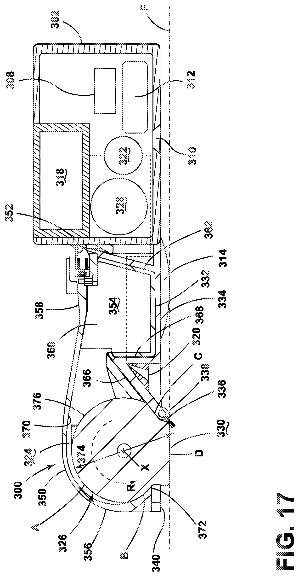
XML
uspto.report is an independent third-party trademark research tool that is not affiliated, endorsed, or sponsored by the United States Patent and Trademark Office (USPTO) or any other governmental organization. The information provided by uspto.report is based on publicly available data at the time of writing and is intended for informational purposes only.
While we strive to provide accurate and up-to-date information, we do not guarantee the accuracy, completeness, reliability, or suitability of the information displayed on this site. The use of this site is at your own risk. Any reliance you place on such information is therefore strictly at your own risk.
All official trademark data, including owner information, should be verified by visiting the official USPTO website at www.uspto.gov. This site is not intended to replace professional legal advice and should not be used as a substitute for consulting with a legal professional who is knowledgeable about trademark law.