Consumable Cartridge For An Aerosol Generation Device
Kind Code
U.S. patent application number 16/639370 was filed with the patent office on 2020-08-13 for consumable cartridge for an aerosol generation device. This patent application is currently assigned to JT International S.A.. The applicant listed for this patent is JT International S.A.. Invention is credited to Spyridon Nompilakis, Andrew Robert John Rogan.
| Application Number | 20200253281 16/639370 |
| Document ID | 20200253281 / US20200253281 |
| Family ID | 1000004813475 |
| Filed Date | 2020-08-13 |
| Patent Application | download [pdf] |

| United States Patent Application | 20200253281 |
| Kind Code | A1 |
| Rogan; Andrew Robert John ; et al. | August 13, 2020 |
Consumable Cartridge For An Aerosol Generation Device
Abstract
A consumable cartridge for an aerosol generation device includes a threaded casing configured to engage with the aerosol generation device. The cartridge further comprises an aerosol forming material that can form an aerosol upon receiving heat, the aerosol forming material located within the threaded casing. Heat is transferred conductively through the threaded casing to the aerosol forming material.
| Inventors: | Rogan; Andrew Robert John; (Forres Grampian, GB) ; Nompilakis; Spyridon; (Kilfisia, GR) | ||||||||||
| Applicant: |
|
||||||||||
|---|---|---|---|---|---|---|---|---|---|---|---|
| Assignee: | JT International S.A. Geneva CH |
||||||||||
| Family ID: | 1000004813475 | ||||||||||
| Appl. No.: | 16/639370 | ||||||||||
| Filed: | September 24, 2018 | ||||||||||
| PCT Filed: | September 24, 2018 | ||||||||||
| PCT NO: | PCT/EP2018/075805 | ||||||||||
| 371 Date: | February 14, 2020 |
| Current U.S. Class: | 1/1 |
| Current CPC Class: | A24F 40/42 20200101; A24F 40/46 20200101 |
| International Class: | A24F 40/46 20060101 A24F040/46; A24F 40/42 20060101 A24F040/42 |
Foreign Application Data
| Date | Code | Application Number |
|---|---|---|
| Sep 25, 2017 | EP | 17192998.7 |
Claims
1-15. (canceled)
16. An aerosol generation system, comprising: an aerosol generation device; and a consumable cartridge for an aerosol generation device, the consumable cartridge comprising: a threaded casing arranged to threadably engage with the aerosol generation device; and an aerosol forming material adapted to form an aerosol upon receiving heat, the aerosol forming material located within the threaded casing, whereby heat is transferred conductively through the threaded casing to the aerosol forming material; wherein the aerosol generating device comprises a region for engaging with the threaded casing of the consumable cartridge.
17. The aerosol generation system of claim 16, wherein the casing is externally threaded.
18. The aerosol generation system of claim 16, wherein the cartridge further comprises a top portion comprising one or more vent holes, and a bottom threaded portion, such that heat causes the aerosol to exit the cartridge through the one or more vent holes.
19. The aerosol generation system of claim 18, wherein the bottom threaded portion is longer than the top portion.
20. The aerosol generation system of claim 16, wherein the threaded casing comprises a thermally conductive material.
21. The aerosol generation system of claim 20, wherein the thermally conductive material is selected from the group comprising Aluminium, Iron, Copper, Zinc, Nickel, Chrome and alloys thereof.
22. The aerosol generation system of claim 20, wherein the thermally conductive material is ceramic.
23. The aerosol generation system of claim 16, wherein the casing comprises metal.
24. The aerosol generation system of claim 16, wherein the casing comprises an electrically resistive portion configured to be energised to generate heat.
25. The aerosol generation system of claim 16, wherein the region for engaging with the threaded casing comprises a complementary thread.
26. The aerosol generation system of claim 16, wherein the aerosol generation device further comprises a heater, wherein the region for engaging with the threaded casing is in thermal contact with the heater, the heater configured to heat the aerosol forming material via the threaded casing.
27. The aerosol generation system of claim 16, wherein the aerosol generation device further comprises an electrical power source electrically connectable to the consumable cartridge, such that the consumable cartridge is configured to generate heat through resistive heating.
28. A method of generating vapour comprising: threadably connecting a consumable cartridge to an aerosol generation device; and applying heat through threads of the consumable cartridge to generate an aerosol from an aerosol generating material arranged in the consumable cartridge.
Description
CROSS-REFERENCE TO RELATED APPLICATIONS
[0001] The present application is a national phase entry under 35 U.S.C. .sctn. 371 of International Application No. PCT/EP2018/075805, filed Sep. 24, 2018, published in English, which claims priority to European Application No. 17192998.7 filed Sep. 25, 2017, the disclosures of which are incorporated herein by reference.
BACKGROUND OF THE INVENTION
[0002] The present invention relates to a consumable cartridge for use with an aerosol generation device.
[0003] A number of new generation smoking devices have been introduced that seek to provide an alternative to conventional cigarettes. One such device is described in EP 2772148A2. In this arrangement a smoking device is provided with a mouthpiece, a casing, an electrical heater and a battery. A consumable cartridge can be installed in the device adjacent the heater. The consumable cartridge has a casing which encloses tobacco material. The cartridge also includes perforations and aeration wells. The heater can heat the casing of the cartridge, causing the tobacco contained within to heat without burning, which releases an aerosol. This aerosol or vapour can then be inhaled by a user through the mouthpiece.
[0004] After a period of use the consumable cartridge becomes depleted. A user can then remove and replace the consumable cartridge.
[0005] It may be desirable to improve the efficiency of the heat transfer to the tobacco within the cartridge. It may also be desirable to be able to securely and removably attach the cartridge within the device.
BRIEF SUMMARY OF THE INVENTION
[0006] According to an aspect of the invention there is provided a consumable cartridge for an aerosol generation device, the consumable cartridge comprising: a threaded casing arranged to threadably engage with the aerosol generation device; an aerosol forming material adapted to form an aerosol upon receiving heat, the aerosol forming material located within the threaded casing.
[0007] In this way, heat may be transferred conductively through the outer casing to the aerosol forming material.
[0008] Advantageously, having the threaded casing provides a secure attachment when the cartridge is provided within the aerosol generation device. This further provides an easy way to remove the cartridge once the aerosol forming material has been consumed.
[0009] Advantageously, having the aerosol forming material within the outer casing allows improved transfer of heat between the aerosol generation device and the cartridge, as the heat is transferred conductively through the outer casing to the aerosol forming material.
[0010] Preferably, the aerosol forming material can form an aerosol upon receiving heat from the aerosol generation device via the threaded casing. Having a threaded connection to transfer heat from the aerosol generation device to the cartridge can increase the surface area of the cartridge that is in contact with the aerosol generation device. This enables better heat transfer to the aerosol forming material. This provides an efficient system as less energy may be required to heat the aerosol forming material.
[0011] The aerosol forming material may include a carrier material, which may include a mixture of propylene glycol (PG) and/or glycerin (G). Preferably, the carrier material has a composition of at least 20 wt %. The aerosol forming material may include ground tobacco particles (e.g. in addition to the carrier material). The aerosol forming material may include other materials, such as a flavouring and water etc.
[0012] Preferably the threaded casing is configured to engage a complementary thread on the aerosol generation device. This can provide a more secure connection between the consumable cartridge and the aerosol generation device. Furthermore, the surface area of contact can be increased further leading to a more efficient transfer of heat.
[0013] The gender of the complementary threaded regions may be opposite to one another. The threaded casing may be a male thread and the complementary thread on the aerosol generation device may be a female thread, or vice versa.
[0014] The pitch of the threaded casing and the complementally threaded regions may be selected for purpose. Preferably, they may comprise at least two threads. Alternatively, they may include three, four, five, or more threads. Preferably the mentioned threads are arranged along a pod slide length of 5-20 mm. This may ensure optimum heat transmission balanced against ease of insertion of the cartridge. Having a pitch that is too fine (lots of threads per axial distance) may not be not optimal as removal and replacement of the cartridge may take too long.
[0015] In one arrangement the aerosol generation device may comprise a region with no thread into which the threaded casing can be screwed. For instance, this region may be made of a soft material such as rubber or soft plastic. Alternatively, a rim may be provided onto which the threaded casing can be screwed and attached.
[0016] Preferably, the casing is externally threaded. Advantageously, this can provide a secure connection and efficient transfer of heat to the cartridge. In other embodiments the casing may comprise a recessed region which is threaded. In this instance the casing may be internally threaded.
[0017] Preferably, the cartridge comprises a top portion comprising one or more vent holes, and a bottom threaded portion, such that heat causes the aerosol to exit the cartridge through the one or more vent holes. This may enable the flow of aerosol to be directed in one direction towards the mouthpiece of the aerosol generation device. For instance, the heat may be received from the aerosol generation device via the bottom threaded portion causing the aerosol to exit through the vent holes in the top portion.
[0018] In other arrangements the top portion may be open and the bottom threaded portion may be closed. Alternatively, or in addition, the top portion may be closed by a perforable member.
[0019] Preferably, the threaded casing comprises a thermally conductive material. Advantageously, this enables efficient transfer of heat from the aerosol generation device to the cartridge. The thermally conductive material may be selected from the group comprising containing Aluminium, Iron, Copper, Zinc, Nickel, Chrome or alloys thereof. Alternatively, the thermally conductive material may be ceramic.
[0020] Preferably, the bottom threaded portion is longer than the top portion. By providing the threaded portion along substantially the entire length of the casing may improve the transfer of heat from the aerosol generation device to the aerosol forming material, improving the efficiency of the device.
[0021] Preferably, the casing of the consumable cartridge comprises metal. Advantageously, metal casing provides reliable protection for the contents of the cartridge. Metal casing is also capable of withstanding the temperatures at which the device operates and for conducting heat towards the aerosol forming material. Alternatively, the consumable cartridge may be comprised of another type of material, such as ceramic or high temperature plastic.
[0022] In one arrangement the casing comprises an electrically resistive portion, which can be energised to generate heat. In this way the heating is directly generated by the consumable cartridge and there is an efficient uniform transfer of heat to the aerosol forming material.
[0023] According to a further aspect of the invention there is provided an aerosol generation system, comprising: the consumable cartridge of any preceding embodiment; an aerosol generation device, comprising: a region for engaging with the threaded casing of the consumable cartridge.
[0024] Advantageously, having the threaded casing provides a secure attachment when the cartridge is inserted within the aerosol generation device. This further provides an easy way to remove the cartridge once the aerosol forming material has been consumed.
[0025] Preferably, the region for engaging with the threaded casing comprises a complementary thread. Preferably, the aerosol generation device further comprises a heater, wherein the region for engaging with the threaded casing is in thermal contact with a heater, the heater configured to heat the aerosol forming material via the threaded casing.
[0026] In some instances, the region for engaging with the threaded casing and the heater may be unitary. Alternatively, they may be separate components.
[0027] Preferably, the aerosol generation device further comprises an electrical power source electrically connectable to the consumable cartridge, such that the consumable cartridge can generate heat through resistive heating. Advantageously, as the heating is directly generated by the consumable cartridge there is an efficient uniform transfer of heat to the aerosol forming material. In some embodiments heating may be provided by both a heater in the aerosol generation device and through resistive heating of the cartridge.
[0028] According to a further aspect there is provided a method of generating vapour comprising: threadably connecting a consumable cartridge to an aerosol generation device; and applying heat through said threads to generate an aerosol from an aerosol generating material arranged in the consumable.
[0029] The method may be performed using the consumable cartridge and the aerosol generation device of the previous aspects.
BRIEF DESCRIPTION OF THE DRAWINGS
[0030] Embodiments of the invention are now described, by way of example, with reference to the drawings, in which:
[0031] FIG. 1 is a front view of a cartridge in an embodiment of the invention;
[0032] FIG. 2 is a side on perspective view of the cartridge depicted in FIG. 1;
[0033] FIG. 3 is a top down perspective view of a portion of an aerosol generation device configured to receive the cartridge depicted in FIGS. 1 and 2;
[0034] FIG. 4 is a side on perspective view of a cartridge according to a further embodiment of the invention;
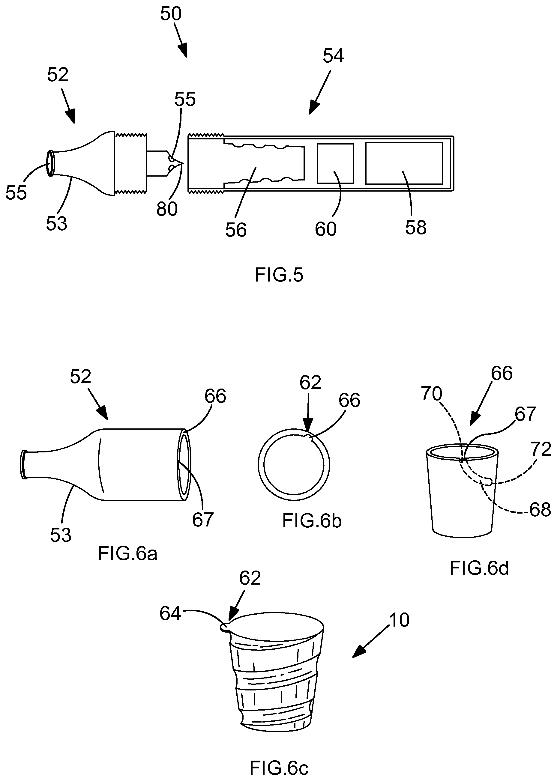
[0035] FIG. 5 is a schematic view of an electronic cigarette according to an embodiment of the present invention;
[0036] FIGS. 6a to 6d are schematic views of a connection system between a mouthpiece portion and a cartridge according to an embodiment, and wherein 6a is a detail of the connection portion of the mouthpiece portion, 6b and 6c represent a schematic top view and a schematic perspective view showing the cooperating connection portion of the cartridge, and FIG. 6d is a detailed schematic perspective view of the connection portion of the mouthpiece portion;
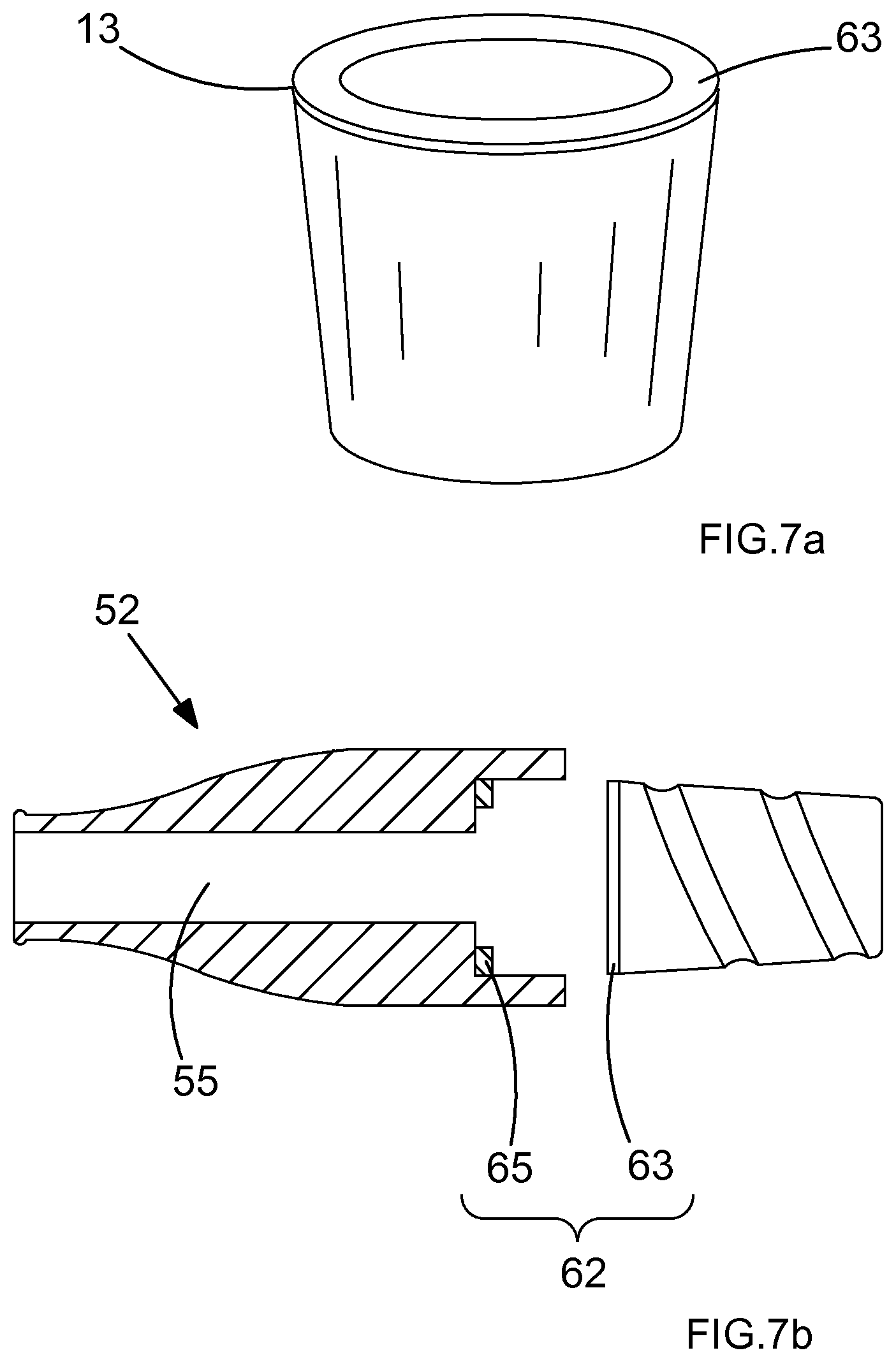
[0037] FIG. 7a is a schematic perspective view of connection portion of a cartridge according to another embodiment of the invention; and
[0038] FIG. 7b is a schematic cross-sectional view of the connection system between the cartridge of FIG. 7a and a cooperating mouthpiece portion.
DETAILED DESCRIPTION
[0039] FIGS. 1 and 2 show a cartridge 10 in a first embodiment of the invention. The cartridge 10 has a generally cylindrical shape. The cartridge 10 has an outer metal casing 13 which accommodates the aerosol generating material, which may be tobacco (11) illustrated using dotted lines as it is located within the cartridge The tobacco material may occupy a portion of the cartridge 10 or may fill the entire of the inside of the cartridge. The aerosol generating material may also comprise tobacco and an aerosol-forming substance such as propylene glycol or glycerine. The tobacco material may also comprise additional components such as flavourings, benzoic acid, tobacco derivatives such as nicotine. A number of other products and ingredients may be provided within the outer casing 13, as will be appreciated by a person skilled in the art.
[0040] The cartridge 10 includes vent holes 12 in an upper surface 14. The cartridge includes a bottom portion 16 which includes a bottom surface 18. The outer metal casing 13 on the bottom portion 16 of the cartridge comprises external threads 20. The upper surface of the cartridge may comprise a rim 13. The threaded region 20 can be seen as protruding sections 20a, 20b, 20c that form the thread 20 that extend around the outer casing 13 of the cartridge 10.
[0041] As can be seen from FIGS. 1 and 2 the threading 20 extends along the length of the bottom portion 16. However, in other embodiments the threading may only extend along only a portion of the bottom portion 16. The threading 20 extends in the radial direction of the cartridge 10. This enables the threading 20 to penetrate into the tobacco material such that heat is transferred to and dispersed within the tobacco material.
[0042] FIG. 3 shows a receiving portion 30 of an aerosol generation device for receiving the cartridge 10 of FIGS. 1 and 2. The receiving portion 30 has a top region 32 with an opening 34. The receiving portion 30 has a cylindrical inner region extending from opening 34 that is matched to receive the cartridge 10. Any shape of inner region could be envisaged so long as that it is matched to, and can accommodate, the shape of the cartridge 10.
[0043] The inner region of the receiving portion 30 is internally threaded 36. The thread 36 can be seen as protruding sections 36a, 36b that form the thread 36 that extends around the inner surface of the inner region of the receiving portion 30. The thread 36 of the receiving portion 30 is complimentary to the thread 20 on the cartridge 10.
[0044] A heater 38 is attached to the bottom region 40 of the receiving portion 30. In other embodiments, the heater may be attached between the bottom region 40 and the top region 42 of the receiving portion 30, as the skilled person would understand.
[0045] In use, the cartridge 10 is inserted into the receiving portion 30 of the aerosol generation device. The cartridge 10 is screwed into the receiving portion 30 through the opening 34, such that the thread 20 on the cartridge 10 engages with the thread 36 on the receiving portion 30. The threads 20, 36 provide a secure attachment between the cartridge 10 and the receiving portion 30, such that the cartridge 10 is securely attached in the aerosol generation device.
[0046] FIG. 5 illustrates an electronic cigarette 50 according to an embodiment of the present invention. The electronic cigarette 50 comprises a mouthpiece portion 52 and a main body portion 54. The main body portion 52 comprises a cartridge seating 56, a power supply unit 58 and a control circuitry 60. The cartridge seating 56 is configured to receive cartridges 10 as described in relation to FIGS. 1 to 4. The mouthpiece portion comprises a mouthpiece 53 and a vapour flow channel 55. The mouthpiece portion 52 may further comprise a piercing element 80. The piercing element 80 is configured to open the cartridge 10 by piercing a vent hole 12 in the top portion 14 of the cartridge 10, such that the vapour can exit the cartridge 10 through the vent hole 12 in the top portion 14.
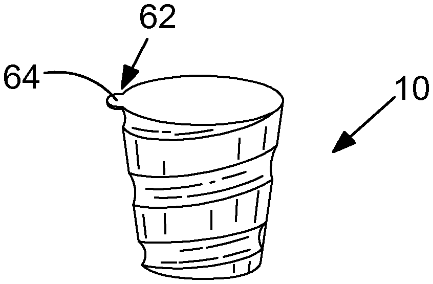
[0047] As seen in FIGS. 6a to 6d, 7a and 7b, the electronic cigarette 50 may comprise connection system 62 configured to facilitate the insertion and removal of the cartridge 10 into and from the cartridge seating 56.
[0048] As seen in FIGS. 6a to 6d, the connection system 62 comprises a first connector 64 located on the cartridge 10 and a second connector 66 located on the mouthpiece portion. The first 64 and the second connector 66 may be configured as cooperating male and female connectors.
[0049] The connection system 62 is thus configured to lock the cartridge 10 to the mouthpiece portion 52 such that the cartridge 10 and mouthpiece portion 52 are locked from relative rotation in at least one rotational direction. This connection system 62 can be a bayonet coupling as illustrated in FIG. 6a.
[0050] The rim 13 of the cartridge 10 can be provided with a radial protrusion 64. The mouthpiece portion 52 can be provided with the second connector 66 comprising a cooperating cut-out 67 and a guide slot 68, having an entry 70 and an end 72. The cartridge 10 can be connected to the mouthpiece portion 52 when the radial protrusion 64 is aligned with the cut-out 67, and locked from rotation when the radial protrusion 64 is in abutment with the end 72 of the guide slot 68.
[0051] The connection system 62 is configured to lock the cartridge 10 to the mouthpiece portion 52. When rotating the cartridge 10 in relation to the mouthpiece portion 52 in a first direction, the mouthpiece portion 52 and the cartridge 10 are locked together. When rotating the cartridge 10 in relation to the mouthpiece portion 52 in a second direction, the mouthpiece portion 52 and the cartridge 10 are unlocked (or disconnected) from each other.
[0052] In another embodiment illustrated in FIGS. 7a and 7b, a magnetic connection system 62 between the cartridge 10 and the mouthpiece portion is provided. The magnetic connection system 62 facilitates the insertion and removal of the cartridge 10. The cartridge 10 can be dislodged from the cartridge seating 56 without having to touch the cartridge 10. This is particularly advantageous if the cartridge 10 is still warm after use. The cartridge 10 comprises a connection portion 63 of a ferromagnetic material. The connection portion 63 can be a located on the upper portion (lid) 14 of the cartridge 10 and may be provided around the rim 13. In other embodiments, the cartridge casing is made of a ferromagnetic material and may therefore act as the cartridge connector. The mouthpiece portion comprises a second connector 65 in the form of a magnet 65.
[0053] In other embodiments, the receiving portion 30 may not have a threaded region 36. For instance, the inner region may be made of plastic or rubber material. The cartridge 10 can then be screwed into the receiving portion 30 with the thread 20 of the cartridge 10 engaging with the soft inner region of the receiving portion 30. In other embodiments rather than the thread, the receiving portion may comprise a lip. The thread 20 of the consumable cartridge 10 is screwed past the lip, such that the entire length of the threaded portion 20 is not engaged with the lip when the cartridge is fully inserted into the receiving portion 30.
[0054] In use, when the cartridge 10 is received within the receiving portion 30 of the aerosol generation device, heat is applied from the aerosol generation device to the cartridge 10. This causes the tobacco within the cartridge 30 to be heated. Vapours that are produced by the tobacco can exit the cartridge 10 through the vent holes 12. It should be understood that although it is shown that the vent holes 12 are on the upper surface 14, the vent holes 12 may be present in any section of the outer casing 13 of the cartridge 10.
[0055] Heat is transferred from the aerosol generation device through the receiving portion 30 being in contact with the threaded 20 outer casing 13 of the cartridge 10. For the embodiments shown in FIGS. 1 to 3, heat is transferred via the complimentary threaded regions 20, 36 of the cartridge 10 and the receiving portion 30 which are in contact with one another. This provides an increase surface area of contact between the cartridge 10 and the receiving portion 30.
[0056] In embodiments where there is no threaded region 36 in the receiving portion 30, heat is transferred through the contact of the threaded portion 20 of the cartridge 10 being engaged with the inner surface of the receiving portion 30.
[0057] Heat is provided from a heater 38 in the aerosol generation device, which is in thermal contact with the receiving portion 30. The heater 38 causes the receiving portion 30 to heat enabling the transfer of the heat through the receiving portion 30 to the cartridge 10 through the threaded casing 13.
[0058] A further embodiment is shown in FIG. 4 which shows an embodiment where the cartridge itself is a heater. In this embodiment the receiving portion 30 may, or may not, have a heater 38.
[0059] As can be seen a wire 40 is helically wound around the cartridge 10 following the direction of the thread 20. In FIG. 4 the wire 40 is located within a recess of the thread 20, such that the wire 40 does not interfere with the threading action of the thread 20. In other embodiments the wire 40 may be located inside the casing 13 of the cartridge 10. A first end of the wire 42 is attached to a positive polarity and the second end of the wire 44 is attached to the opposite negative polarity.
[0060] An electric current is applied to the wire 40 via an electrical power source. This causes the wire 40 to heat through resistive heating, transferring heat to the cartridge 10 causing the aerosol generation material contained therein to be heated.
[0061] Alternatively, the wire 40 may be two wires, which are insulated from one another along the length of the cartridge 10 to prevent a short circuit. The wires being electrically connected to one another near one end of the cartridge 10. This means the electrical power only needs to be supplied at one end of the cartridge 10.
* * * * *
D00000
D00001
D00002
D00003
XML
uspto.report is an independent third-party trademark research tool that is not affiliated, endorsed, or sponsored by the United States Patent and Trademark Office (USPTO) or any other governmental organization. The information provided by uspto.report is based on publicly available data at the time of writing and is intended for informational purposes only.
While we strive to provide accurate and up-to-date information, we do not guarantee the accuracy, completeness, reliability, or suitability of the information displayed on this site. The use of this site is at your own risk. Any reliance you place on such information is therefore strictly at your own risk.
All official trademark data, including owner information, should be verified by visiting the official USPTO website at www.uspto.gov. This site is not intended to replace professional legal advice and should not be used as a substitute for consulting with a legal professional who is knowledgeable about trademark law.