System and Methods for Calibration of an Array Camera
Kind Code
U.S. patent application number 16/785914 was filed with the patent office on 2020-08-06 for system and methods for calibration of an array camera. This patent application is currently assigned to FotoNation Limited. The applicant listed for this patent is FotoNation Limited. Invention is credited to Robert Mullis.
| Application Number | 20200252597 16/785914 |
| Document ID | 20200252597 / US20200252597 |
| Family ID | 1000004767767 |
| Filed Date | 2020-08-06 |
| Patent Application | download [pdf] |


| United States Patent Application | 20200252597 |
| Kind Code | A1 |
| Mullis; Robert | August 6, 2020 |
System and Methods for Calibration of an Array Camera
Abstract
Systems and methods for calibrating an array camera are disclosed. Systems and methods for calibrating an array camera in accordance with embodiments of this invention include the capturing of an image of a test pattern with the array camera such that each imaging component in the array camera captures an image of the test pattern. The image of the test pattern captured by a reference imaging component is then used to derive calibration information for the reference component. A corrected image of the test pattern for the reference component is then generated from the calibration information and the image of the test pattern captured by the reference imaging component. The corrected image is then used with the images captured by each of the associate imaging components associated with the reference component to generate calibration information for the associate imaging components.
| Inventors: | Mullis; Robert; (Santa Cruz, CA) | ||||||||||
| Applicant: |
|
||||||||||
|---|---|---|---|---|---|---|---|---|---|---|---|
| Assignee: | FotoNation Limited Galway IE |
||||||||||
| Family ID: | 1000004767767 | ||||||||||
| Appl. No.: | 16/785914 | ||||||||||
| Filed: | February 10, 2020 |
Related U.S. Patent Documents
| Application Number | Filing Date | Patent Number | ||
|---|---|---|---|---|
| 16290672 | Mar 1, 2019 | 10560684 | ||
| 16785914 | ||||
| 15987768 | May 23, 2018 | 10225543 | ||
| 16290672 | ||||
| 14841651 | Aug 31, 2015 | 9986224 | ||
| 15987768 | ||||
| 14519005 | Oct 20, 2014 | 9124864 | ||
| 14841651 | ||||
| 13792143 | Mar 10, 2013 | 8866912 | ||
| 14519005 | ||||
| Current U.S. Class: | 1/1 |
| Current CPC Class: | G06T 2207/10012 20130101; H04N 5/23245 20130101; H04N 5/23232 20130101; G06T 2207/10024 20130101; H04N 13/243 20180501; H04N 13/246 20180501; H04N 13/257 20180501; H04N 17/002 20130101; H04N 17/02 20130101; H04N 13/282 20180501; G06T 2207/20048 20130101; G06T 7/85 20170101 |
| International Class: | H04N 13/246 20060101 H04N013/246; H04N 17/02 20060101 H04N017/02; H04N 5/232 20060101 H04N005/232; G06T 7/80 20060101 G06T007/80; H04N 13/282 20060101 H04N013/282; H04N 13/257 20060101 H04N013/257; H04N 13/243 20060101 H04N013/243; H04N 17/00 20060101 H04N017/00 |
Claims
1-19. (canceled)
20. A method for manufacturing an array camera device, the method comprising: assembling an array of cameras comprising a plurality of imaging components that capture images of a scene from different viewpoints; configuring the array of cameras to communicate with at least one processor; configuring the processor to communicate with at least one type of memory; and loading calibration information into the memory by: loading a reference set of scene independent geometric corrections for image data captured by a first imaging component of the plurality of imaging components derived from test pattern image data captured by the first imaging component and data describing the test pattern using the processor; and loading an associate set of scene independent geometric corrections for image data captured by a second imaging component of the plurality of imaging components, wherein the associate set of scene independent geometric corrections is derived using test pattern image data captured by the second imaging component and data for a corrected test pattern image, wherein the corrected test pattern image is captured by the first imaging component and corrected using the reference set of scene independent geometric corrections.
21. The method of claim 1, wherein the first imaging component is a reference imaging component and the second imaging component is an associate imaging component, wherein the calibration information comprises: reference calibration information for the reference imaging component comprising the scene independent geometric corrections for reference image data captured by the reference imaging component to account for distortions related to the mechanical construction of the reference imaging component and produce a corrected reference image; and associate calibration information for the associate imaging component comprising the scene independent geometric corrections for associate image data captured by the associate imaging component that map locations of pixels in an image captured by the associate imaging component to corresponding pixel locations in the corrected reference image, where corresponding pixel locations represent the same point in a scene in the absence of disparity due to parallax.
22. The method of claim 2, wherein the calibration information further comprises colorimetric corrections or photometric corrections for image data captured by one or more imaging components of the plurality of imaging components.
23. The method of claim 2, further comprising loading a software application comprising machine readable instructions into the memory, where execution of the software application by the processor directs the processor to: capture images of a scene using the plurality of imaging components in the array of cameras, wherein the captured images comprise: an associate image captured by the associate imaging component; and a reference image captured by the reference imaging component; apply corrections to locations of pixels of the associate image using the associate calibration information; generate a depth map by measuring disparity due to parallax between pixels in the reference image and corrected pixels in the associate image; and synthesize an image using the generated depth map and at least some of the pixels from the captured images.
24. The method of claim 4, wherein the execution of the software application by the processor further directs the processor to apply corrections to locations of pixels of the reference image using the reference calibration information; and wherein the depth map is generated by measuring disparity due to parallax between the corrected pixels in the reference image and the corrected pixels in the associate image.
25. The method of claim 1 further comprising capturing the test pattern image data using the array of cameras, wherein the test pattern is placed at a defined distance away from the array of cameras when the images of the test pattern are captured, and the distance is at least 70 percent of a hyperfocal distance of the array of cameras.
26. The method of claim 1 further comprising capturing the test pattern image data using the array of cameras, wherein the test pattern is placed at a defined distance away from the array of cameras when the images of the test pattern are captured, and the distance is at least 50 percent of a hyperfocal distance of the array of cameras.
27. The method of claim 1, wherein the test pattern includes a low-contrast slanted edge pattern.
28. The method of claim 8, wherein the test pattern includes a plurality of Macbeth Color Chart type patterns inset at different positions in the low-contrast slanted pattern.
29. The method of claim 1, further comprising performing at least one pass/fail test of the array of cameras based on captured images of the test pattern to verify proper image capture by the plurality of imaging components.
30. The method of claim 1 further comprising generating the reference set of scene independent geometric corrections by: identifying reference intersection points in the image of the test pattern captured by the reference imaging component; determining uniformity characteristics of the reference imaging component from reference intersection points and the test pattern; and deriving parameters for the reference imaging component to compensate for low frequency aberrations in the image of the test pattern captured by the reference imaging component.
31. The method of claim 1, wherein the first imaging component is a reference imaging component and the second imaging component is an associate imaging component, wherein the method further comprises generating the associate set of scene independent geometric corrections by: identifying associate intersection points in images of the test pattern captured by the associate imaging component; translating associate intersection points in accordance with an expected parallax shift for the associate imaging component relative to the reference imaging component; and deriving parameters for the associate imaging component to compensate for low frequency aberrations in the image of the test pattern captured by the associate imaging component by comparing translated associate intersection points to corresponding intersection points in the corrected test pattern image for the reference imaging component.
32. The method of claim 12, wherein the expected parallax shift for the associate imaging component is based upon at least one of the physical offset of the associate imaging component to the reference imaging component, the behavior of sensor optics in the associate imaging component, and a distance of the test pattern from the array of cameras.
33. The method of claim 1, further comprising: generating colorimetric corrections or photometric corrections for image data captured by each imaging component in the array of cameras using test pattern image data captured by each imaging component using the processor; and storing the generated colorimetric corrections or photometric corrections in the memory.
34. The method of claim 1, wherein the array of cameras includes more than one reference imaging component.
35. The method of claim 1, wherein the processor includes a graphics processing unit.
36. The method of claim 1, wherein the associate set of scene independent geometric corrections are represented by a grid that provides a geometric correction prescription for pixels of the second imaging component.
37. The method of claim 1, wherein the plurality of imaging components are configured in a 5.times.5 array.
38. The method of claim 1, wherein at least one imaging component of the plurality of imaging components contains a lens stack array and at least one sensor element, where the sensor element is selected from the group of a traditional CIS (CMOS Image Sensor) pixel, a CCD (charge-coupled device) pixel, a high dynamic range sensor element, a multispectral sensor element, and a structure configured to generate an electrical signal indicative of light incident on the structure.
Description
CROSS-REFERENCE TO RELATED APPLICATION
[0001] This application is a continuation of U.S. patent application Ser. No. 16/290,672 entitled "System and Methods for Calibration of an Array Camera" filed on Mar. 1, 2019 which application claims priority as a continuation of U.S. patent application Ser. No. 15/987,768 entitled "System and Methods for Calibration of an Array Camera" filed on May 23, 2018, and issued on Mar. 5, 2019 as U.S. Pat. No. 10,225,543 which application claims priority as a continuation of U.S. patent application Ser. No. 14/841,651 entitled "System and Methods for Calibration of an Array Camera" filed on Aug. 31, 2015 and issued on May 29, 2018 as U.S. Pat. No. 9,986,224, which application claims priority as a continuation of U.S. patent application Ser. No. 14/519,005, entitled "System and Methods for Calibration of an Array Camera", filed on Oct. 20, 2014 and issued on Sep. 1, 2015 as U.S. Pat. No. 9,124,864, which application claims priority as a continuation of U.S. patent application Ser. No. 13/792,143, entitled "System and Methods for Calibration of an Array Camera", filed on Mar. 10, 2013 and issued on Oct. 21, 2014 as U.S. Pat. No. 8,866,912, the disclosures of which are incorporated by reference herein in their entireties.
FIELD OF THE INVENTION
[0002] The present invention relates to calibration of an array camera. More particularly, this invention relates to systems and methods for calibrating each imaging component in an array camera.
BACKGROUND
[0003] An array camera is a camera that is made up of multiple imaging components. Each individual imaging component captures data for a two dimensional image of a view. For purposes of this discussion, an imaging component is an individual camera and/or circuitry including an array of pixels that capture data for a two dimensional image of the view. The data of the two-dimensional images used to generate as a light field. A light field can be used to produce super-resolution (SR) images and other types of images of the view using some or all of the data from the various two dimensional images captured by the individual imaging components.
[0004] During the manufacture of most digital cameras (including array cameras) and each imaging component of an array camera, a calibration process is typically performed. In a conventional camera or imaging component, the calibration process typically measures the Modulation Transfer Function (MTF). MTF measurements enable the detection of aberrations that degrade MTF. Some calibration processes may also be used to collect data that characterizes the camera or imaging component in order to adjust the parameters of various image processing algorithms to produce desired images. Typically, the need to obtain precise data during calibration is balanced with the need to keep the manufacturing test overhead to a minimum.
SUMMARY OF THE INVENTION
[0005] Systems and methods in accordance with embodiments of this invention enable calibration of array cameras. In accordance with embodiments of this invention, one or more of the imaging components of the array camera are designated as a reference imaging component and each of the remaining imaging components in the array camera is an associate imaging component. Each of the associate imaging components is associated with at least one of the reference imaging components.
[0006] In some embodiments in accordance with this invention, the calibration process is performed in the following manner. An image of a test pattern is captured by each of the imaging components of the array camera. Scene independent geometric corrections for the image data captured by the reference imaging component is generated using data of the image of the test pattern captured by the reference component and data describing the test pattern using a processor. A corrected image of the test pattern for the reference component is generated based on the scene independent geometric corrections for the image data captured by the reference imaging component and the image of the test pattern captured by the reference imaging component using the processor. Scene independent geometric corrections for the image data captured by each of the associate imaging components associated with the reference imaging component using the data of image of the test pattern captured by each associate imaging component and the corrected image of the reference component using the processor.
[0007] In some embodiments in accordance with the invention, the test pattern includes a low-contrast slanted edge pattern. In accordance with some of these embodiments, the test pattern includes a plurality of Macbeth Color Chart type patterns inset at different positions in the low-contrast slanted pattern.
[0008] In accordance with some embodiments, the test pattern is at a distance of at least 70 percent of the hyperfocal distance of the array camera away from the array camera during the capturing of the image of the test pattern. In accordance with other embodiments, the test pattern is at a distance of at 50 percent of the hyperfocal distance of the array camera away from the array camera during the capturing of the image of the test pattern. In some embodiments in accordance with this invention, at least one pass/fail test of the array camera is performed based on images of the test pattern captured by the plurality of imaging components in the array camera.
[0009] In some embodiments in accordance with this invention, the generating of scene independent geometric corrections for the image data captured by the reference imaging component using data of the image of the test pattern captured by the reference component and data describing the test pattern is performed in the following manner. The intersection points in the image of the test pattern captured by the reference imaging component are identified. Uniformity characteristics of the reference imaging component are determined from the identified intersection points in the image of the test pattern captured by the reference imaging component and the test pattern. A set of geometric corrections for the reference imaging component is derived to compensate for low frequency aberrations in the captured image of the test pattern.
[0010] In some embodiments, the generating of scene independent geometric corrections for the image data captured by each of the associate imaging components associated with the reference imaging component is performed in the following manner. The intersection points in the test pattern image captured by each of the associate imaging components are identified. The intersection points from the captured test pattern images captured by each of the associate imaging components associated with the reference component are translated in accordance with an expected parallax shift for each of the associate imaging components relative to the reference component. A set of geometric corrections for each of the associate imaging components associated with the reference component to compensate for low frequency aberrations in the captured image of the test pattern by comparing the translated intersections points in the images captured by each of the associate imaging components to corresponding intersection points in the corrected image for the reference component. In some of these embodiments, the expected parallax shift for each of the associate imaging components is based upon at least one of the physical offset of a particular imaging component to the reference imaging component, the behavior of sensor optics in the particular associate imaging component, and distance of the test pattern from the array camera.
[0011] In some embodiments, the images captured by the imaging components are stored in order to perform the calibration of the reference component and each of the plurality of associate imaging components at a later time.
[0012] In some embodiments, the scene dependent geometric correction information for the image data captured by the reference component is stored in a memory. In some embodiment, the scene dependent geometric correction information for the image data captured by each of the associated imaging components associated with the reference component is stored in a memory.
[0013] In accordance with some embodiments, the calibration process further includes generating colorimetric corrections for the image data captured by each imaging component in the array camera using data of the image of the test pattern captured by the each imaging component. In some embodiments, the calibration process further includes generating photometric corrections for the image data captured by each imaging component in the array camera using data of the image of the test pattern captured by the reference component using the processor.
BRIEF DESCRIPTION OF THE DRAWINGS
[0014] FIG. 1 conceptually illustrates an array camera in accordance with an embodiment of this invention.
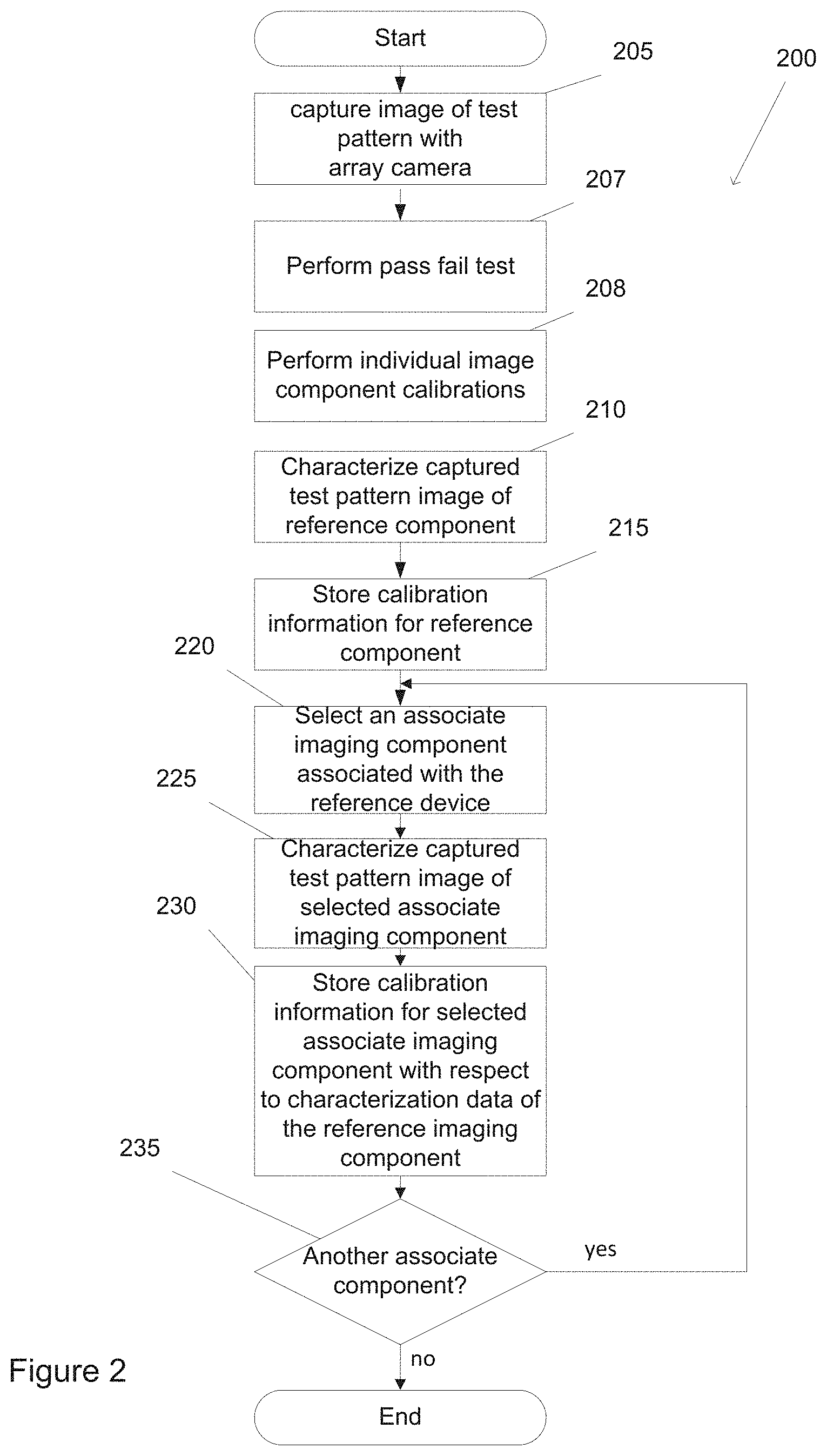
[0015] FIG. 2 illustrates a flow diagram of a calibration process for an array camera in accordance with an embodiment of this invention.
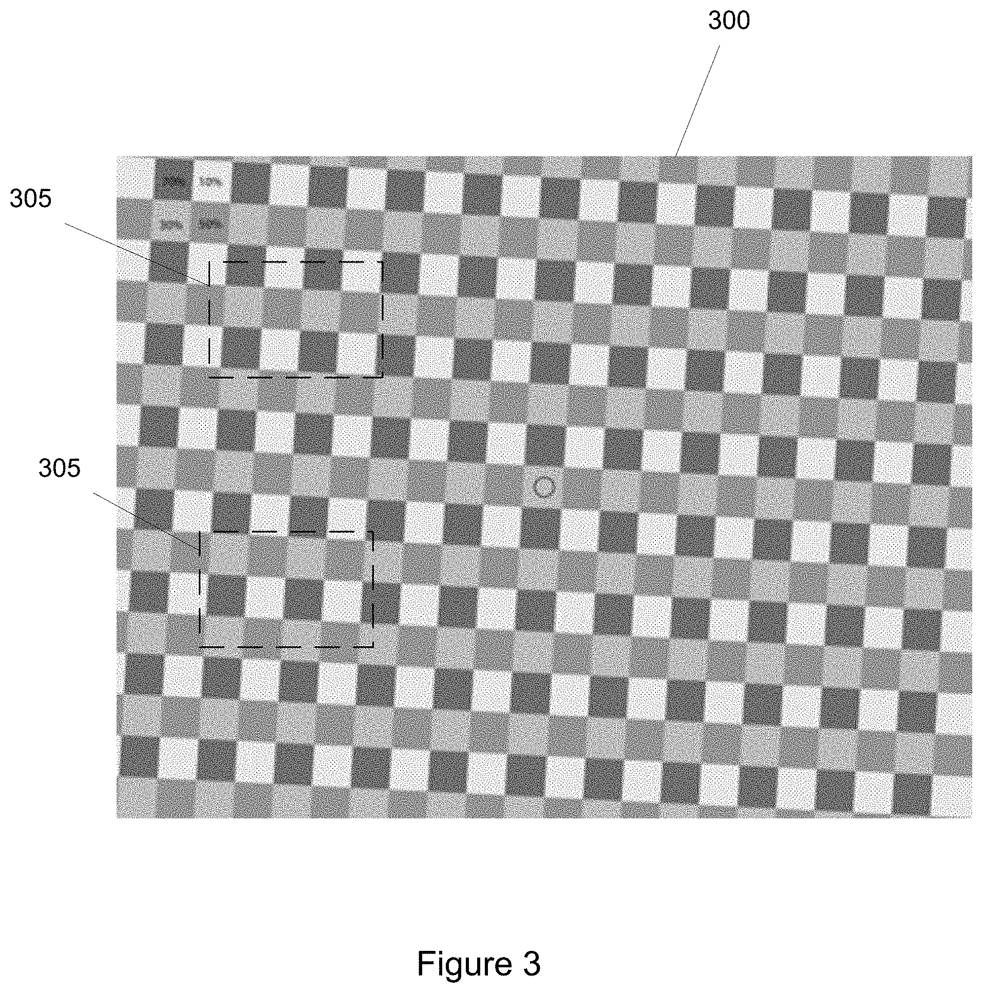
[0016] FIG. 3 illustrates a test pattern for use in a calibration process for an array camera in accordance with an embodiment of this invention.
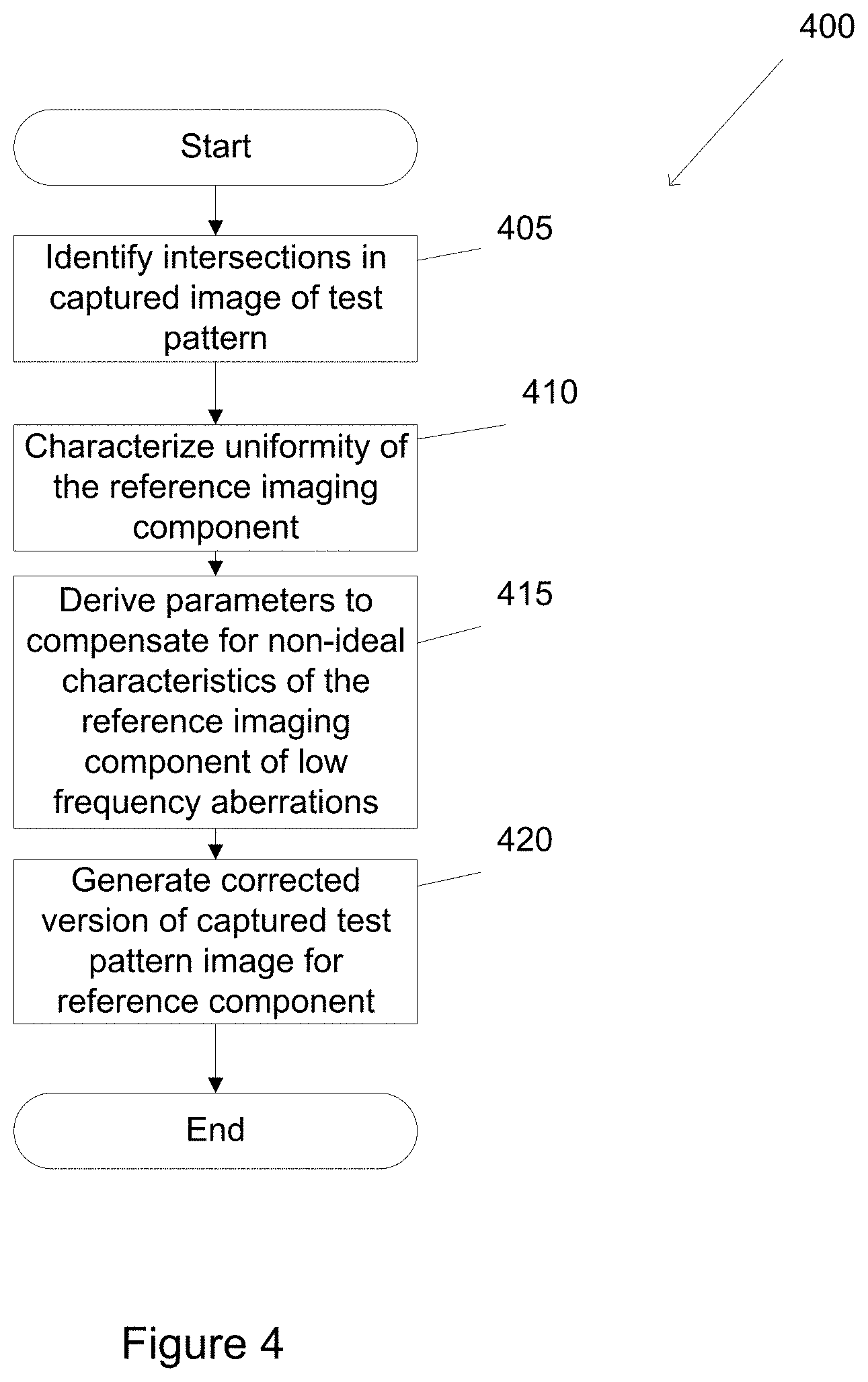
[0017] FIG. 4 illustrates a flow diagram of a process for calibrating a reference imaging component in accordance with embodiments of this invention.
[0018] FIG. 5 illustrates a flow diagram of a process for calibrating an associate imaging component with respect to a reference imaging component in an array camera in accordance with embodiments of this invention.
DETAILED DESCRIPTION
[0019] Turning now to the drawings, systems and methods for performing a calibration process for an array camera in accordance with embodiments of the invention are illustrated. In accordance with many embodiments of the invention, at least one of the imaging components in the array camera is designated as a "master" or "reference" imaging component; and each of the remaining imaging components in the array is an associate imaging component. Each associate imaging component is associated with at least one of the reference imaging components. In several embodiments, a calibration process is performed to determine relevant characteristics of each reference imaging component including (but not limited to) colorimetric and photometric calibration processes, and/or determining scene independent geometric corrections that can be applied to the image data captured by the imaging component to account for distortions related to the mechanical construction of the imaging component. The process then determines relevant characteristics of each of the associate imaging components that are associated with a particular reference component. In a number of embodiments, the characteristics of the associate imaging components are determined with respect to the corresponding characteristics of the associated reference imaging component. In several embodiments, scene independent geometric corrections for the image data captured by an associate imaging component are determined by adjusting the image data captured by the associate image component for parallax and then comparing the parallax adjusted image data to a corrected image, where the corrected image is generated by applying the appropriate scene independent geometric corrections to the image data captured by the reference imaging component (i.e. the scene independent geometric corrections for the image data of the reference imaging component determined during the calibration of the reference imaging component). Systems and methods for calibrating array cameras in accordance with embodiments of the invention are discussed further below.
Capturing Light Field Image Data
[0020] A light field, which is often defined as a 4D function characterizing the light from all direction at all points in a scene, can be interpreted as a two-dimensional (2D) collection of data from 2D images of a scene. Array cameras, such as those described in U.S. patent application Ser. No. 12/935,504 entitled "Capturing and Processing of Images using Monolithic Array camera with Heterogeneous Imagers" to Venkataraman et al., can be utilized to capture light field images. In a number of embodiments, super resolution processes such as those described in U.S. patent application Ser. No. 12/967,807 entitled "Systems and Methods for Synthesizing High Resolution Images Using Super-Resolution Processes" to Lelescu et al., are utilized to synthesize a higher resolution 2D image or a stereo pair of higher resolution 2D images from the lower resolution image data in the light field captured by the imaging components in an array camera. The terms high or higher resolution and low or lower resolution are used here in a relative sense and not to indicate the specific resolutions of the images captured by the array camera. The super resolution processing techniques described in U.S. patent application Ser. No. 12/967,807 can utilize a variety of calibration information including scene independent geometric corrections related to the distortions introduced by the construction of the imaging components utilized to capture the lower resolution image data. Scene independent distortions introduced by the imaging components of an array camera can limit the fidelity of a higher resolution image generated by super resolution imaging due to uncertainty concerning the relevant location within the scene of a piece of image data. By measuring the distortions during calibration, the uncertainty introduced by the distortions can be reduced, improving the performance of the super resolution process. In a similar manner, colorimetric and photometric variation between similar imaging components in a array camera can complicate image processing by increasing the difficulty of identifying similar points within a scene in the image data captured by the imaging components. The disclosures of U.S. patent application Ser. No. 12/935,504 and U.S. patent application Ser. No. 12/967,807 are hereby incorporated by reference in their entirety.
[0021] Each two-dimensional (2D) image in a captured light field is from the viewpoint of one of the imaging components in the array camera. A high resolution image synthesized using super resolution processing is synthesized from a specific viewpoint that can be referred to as a reference viewpoint. The reference viewpoint can be from the viewpoint of one of the imaging components in an array camera. Alternatively, the reference viewpoint can be an arbitrary virtual viewpoint.
[0022] Due to the different viewpoint of each of the imaging components, parallax results in variations in the position of foreground objects within the captured images of the scene. Processes for performing parallax detection are discussed in U.S. Provisional Patent Application Ser. No. 61/691,666 entitled "Systems and Methods for Parallax Detection and Correction in Images Captured Using Array Cameras" to Venkataraman et al., the disclosure of which is incorporated by reference herein in its entirety. As is disclosed in U.S. Provisional Patent Application Ser. No. 61/691,666, a depth map from a reference viewpoint can be generated by determining the disparity between the pixels in the images within a light field due to parallax. A depth map indicates the distance of the surfaces of scene objects from a reference viewpoint. In a number of embodiments, the computational complexity of generating depth maps is reduced by generating an initial low resolution depth map and then increasing the resolution of the depth map in regions where additional depth information is desirable such as (but not limited to) regions involving depth transitions and/or regions containing pixels that are occluded in one or more images within the light field.
[0023] During super resolution processing, a depth map can be utilized in a variety of ways. U.S. patent application Ser. No. 12/967,807 describes how a depth map can be utilized during super resolution processing to dynamically refocus a synthesized image to blur the synthesized image to make portions of the scene that do not lie on the focal plane to appear out of focus. U.S. patent application Ser. No. 12/967,807 also describes how a depth map can be utilized during super resolution processing to generate a stereo pair of higher resolution images for use in 3D applications. A depth map can also be utilized to synthesize a high resolution image from one or more virtual viewpoints. In this way, a rendering device can simulate motion parallax and dolly zoom. In addition to utilizing a depth map during super-resolution processing, a depth map can be utilized in a variety of post processing processes to achieve effects including (but not limited to) dynamic refocusing, generation of stereo pairs, and generation of virtual viewpoints without performing super-resolution processing.
Array Camera Architecture
[0024] Array cameras in accordance with embodiments of the invention are configured so that the array camera software can control the capture of light field image data and can capture the light field image data into a file that can be used to render one or more images on any of a variety of appropriately configured rendering devices. An array camera including an array of imaging components in accordance with an embodiment of the invention is illustrated in FIG. 1. The array camera 100 includes an array camera module 102, a processor 108, a memory 110 and a display 112. The array camera module 102 includes an array of imaging components 104 formed by a sensor and a lens stack array and the array camera module 102 is configured to communicate with a processor 108. The processor 108 is also configured to communicate with one or more different types of memory 110 that can be utilized to store image data and/or contain machine readable instructions utilized to configure the processor to perform processes including (but not limited to) the various processes described below. The processor 108 may also be connected to a network via a network connection 106 to communicate with other processing systems connected to the network. The display 112 can be utilized by the processor 108 to present a user interface to a user and to display an image rendered using the light field image data. Although the processor is illustrated as a single processor, array cameras in accordance with embodiments of the invention can utilize a single processor or multiple processors including (but not limited to) a graphics processing unit (GPU).
[0025] In the illustrated embodiment, the processor 108 receives image data generated by the array camera module 102 and reconstructs the light field captured by the array camera module 102 from the image data. Sensors including multiple focal planes that can be utilized in the construction of array camera modules are discussed in U.S. patent application Ser. No. 13/106,797 entitled "Architectures for System on Chip Array Cameras", to Pain et al., the disclosure of which is incorporated herein by reference in its entirety. The processor 108 can manipulate the light field in any of a variety of different ways including (but not limited to) determining the depth and visibility of the pixels in the light field and synthesizing higher resolution 2D images from the image data of the light field.
[0026] In the illustrated embodiment, the imaging components 104 are configured in a 5.times.5 array. Each imaging component 104 in the array camera module 102 is capable of capturing an image of the view. The sensor elements utilized in the imaging components 104 can be individual light sensing elements such as, but not limited to, traditional CIS (CMOS Image Sensor) pixels, CCD (charge-coupled device) pixels, high dynamic range sensor elements, multispectral sensor elements and/or any other structure configured to generate an electrical signal indicative of light incident on the structure. In many embodiments, the sensor elements of the imaging components 104 have similar physical properties and receive light via the same optical channel and color filter (where present). In other embodiments, the sensor elements of the imaging components 104 have different characteristics and, in many instances, the characteristics of the sensor elements are related to the color filter applied to each sensor element. In several embodiments, the sensor elements of an imaging component includes a plurality of rows of pixels that also form a plurality of columns of pixels and the pixels of each imaging component are contained within a region of the sensor that does not contain pixels from another imaging component.
[0027] In many embodiments, an array of images (i.e. a light field) is created using the image data captured by the imaging components 104. As noted above, the processor 108 in accordance with many embodiments of the invention are configured using appropriate software to take the image data within the light field and synthesize one or more high resolution images. In several embodiments, the high resolution image is synthesized from a reference viewpoint, typically that of a reference imaging component 104 within the array camera module 102. In many embodiments, the processor is able to synthesize an image from a virtual viewpoint, which does not correspond to the viewpoints of any of the imaging components 104 in the array camera module 102. Unless all of the objects within a captured scene are a significant distance from the array camera, the images in the light field will include disparity due to the different fields of view of the focal planes used to capture the images. Processes for detecting and correcting for disparity when performing super resolution processing in accordance with embodiments of the invention are discussed in U.S. Provisional Patent Application Ser. No. 61/691,666 (incorporated by reference above). The detected disparity can be utilized to generate a depth map. The high resolution image and depth map can be encoded and stored in memory 110 in a light field image file. The processor 108 can use the light field image file to render one or more high resolution images. The processor 108 can also coordinate the sharing of the light field image file with other devices (e.g. via a network connection), which can use the light field image file to render one or more high resolution images.
[0028] Although a specific array camera architecture is illustrated in FIG. 1, systems and methods for performing calibration of an array camera in accordance with embodiments of the invention may be performed on any array camera configuration appropriate to the requirements of a specific application. Systems and methods for performing a calibration process for an array camera in accordance with embodiments of the invention are discussed below.
Calibration Process for an Array Camera
[0029] An array camera has features beyond those in a conventional camera that are characterized during calibration to assist super resolution processing algorithms to produce images of a desired resolution. The information obtained during calibration can include a Field of View (FoV) for each of the imaging components in the array and other information that relates one or more imaging components to one another. In many embodiments, the calibration process determines parameters utilized by driver software to adjust the imaging component alignment data that drives normalization and parallax compensation processing in preparation for super resolution processing. Typically, this information is obtained by using the imaging components in the array to capture images of specialized charts. These calibration processes often involve significant physical space and substantial data management to obtain useful information. The space and data management requirements can be a problem in the manufacturing process of an array camera, where both physical space and data storage can be at a premium.
[0030] To reduce the amount of physical space needed and data storage requirements for calibration, processes for calibrating an array camera in accordance with many embodiments of the invention involve capturing an image of a test pattern with each of the imaging components in the array. The captured images can be utilized to calibrate a reference imaging component, generate a corrected image of the test pattern based upon calibration information for the reference component, and calibrate each of the associate imaging components associated with the reference component. In this way, calibration can be performed where the calibration of the associate imaging components is performed with respect to the associated reference component using the corrected image generated for the reference component.
[0031] A process for calibrating an array camera in accordance with an embodiment of the invention is illustrated in FIG. 2. The process 200 includes capturing an image of a test pattern with the array camera (205). Each imaging component in the array camera captures an image of the test pattern. The test pattern has unique properties as discussed below with reference to FIG. 3. In many embodiments, the test pattern is placed at a distance farther away than 50% of the Hyperfocal (HF) distance of the array camera. In accordance with other embodiments, the test pattern is placed at a distance further away than 70% of the HF distance of the array camera. In accordance with still other embodiments, the test patent is a placed a distance from the array camera equal to the average of the HF distances of the individual lens stacks of the imaging components. In most embodiments, the HF distance will be in a range of 20-60 cm or 7.9-23.6 inches away from the array camera. One skilled in the art will recognize that the exact distance requirements will depend on the analysis methods used to calibrate the imaging components and the configuration of the array camera. In a number of the embodiments, the distance between the array camera and the test pattern is sufficient to produce a captured image of a checkerboard pattern with sufficient sharpness to determine a relative position of an object in the captured image to a fraction of a pixel. In some embodiments, the position may be determined within 0.5 of the pixel position or less. In other embodiments, the position may be determined within 0.25 of the pixel position or less. The distance between the array camera and the test pattern can also be used to determine the parallax shift between the imaging components to aid in determination of the relative spatial performance between the imaging components.
[0032] After the images are captured, the images captured by each of the imaging components may be stored in a memory and processed locally in real time or used by an off-line calibration process that can be performed by another processing system or by the processor in the array camera. Furthermore, the images of the test pattern captured by the imaging components in the array camera may be transmitted from the processor 108 of the array camera 100 to another processing system via a network connection 106 to allow the other processing system to perform the calibration process off-line. Various calibration processes that can be performed using the captured images in accordance with embodiments of the invention are discussed further below.
[0033] After each of the imaging components captures an image of the test pattern, some pass/fail tests may be performed (207) to provide gross operational sorting. The pass/fail tests may include but are not limited to, an image evaluation to verify proper image capture by the imaging components and/or to enable material sorting. The image evaluation may look for image levels within expected ranges, identify particular elements in each image such as fiducials (fiduciary markers) or edge detection in an expected area of the image. Failure to identify expected elements in a captured image may indicate a gross failure of the imaging component that captured the image. Other types of pass/fail test may also or alternatively be performed without departing from this invention.
[0034] Individual calibration processes may then be performed for each of the individual imaging components (208). These individual calibration processes may include, but are not limited, to colorimetric and photometric calibration processes. In accordance with some embodiments, a colorimetric calibration process is performed for each of the imaging components by evaluating Macbeth-style Color Checker patterns in the image of the test pattern captured by an imaging component. The values of these patterns in the image are compared to expected values and any deviation is identified and stored for use in the processing pipeline of the array camera. In accordance with some embodiments, the photometric calibration is performed in the following manner. The center of the image is identified based upon the relative brightness in the image. The center typically has the peak brightness of the image. The pixel data is then fitted to a cosine{circumflex over ( )}4 curve using a least squares method. Photometric correction data is then determined by taking the difference between the fitted curve and the desired vignetting profile. The photometric correction data is then stored for use in the processing pipeline. Although specific colorimetric and photometric calibration processes are discussed above, any of a variety of colorimetric and/or photometric calibration processes can be utilized as appropriate to the requirements of specific applications in accordance with embodiments of the invention.
[0035] Characterization of the image of the test pattern captured by a reference imaging component in the array camera (210) is then performed to determine calibration information for the reference imaging component. A reference component is an imaging component in the array camera that is used as a reference for the calibration of one or more of the remaining associate imaging components in the array. In the described embodiment, the array camera only includes one reference component. However, an array camera may include more than one reference imaging component. When the array camera includes more than one reference imaging component, the characterization of the image of the test pattern (210) is repeated for images captured by each of the reference components. Various processes for characterization of the image of the test pattern captured by a reference component in accordance with embodiments of the invention are described below with reference to FIG. 4. The calibration information for the reference imaging component(s) is then stored (215).
[0036] After the image of the reference component(s) is characterized, a process for calibrating each of the associate imaging components associated with each reference imaging component can be performed. First, an associate imaging component associated with the reference component is selected (220). The test pattern image captured by the selected associate imaging component is characterized (225) to determine calibration information for the associate imaging component with respect to the reference imaging component. In many embodiments, the calibration information includes scene independent geometric corrections to account for distortions introduced by the mechanical construction of each imaging component. The calibration information is then stored for the selected associate imaging component (230). The process then determines whether the array camera includes another associate imaging component associated with the reference component (235). If there is another imaging component from the array camera associated with the reference component, the process (220-235) is repeated for the next associate imaging component. If there are no other associated imaging components associated with the reference component, process 200 ends. In some embodiments with more than one reference component, calibration of associate imaging components (220-235) is repeated for each particular reference component and the associate components associated with the particular reference component until the calibration process has been performed for all of reference imaging components and its associated associate components in the array camera.
[0037] A test pattern that can be used in a calibration process in accordance with embodiments of this invention is illustrated in FIG. 3. The test pattern 300 has a low contrast slanted edge pattern. As shown, the test pattern 300 has a checkerboard pattern providing the low contrast slanted edge pattern. The test pattern 300 changes with a high enough frequency to provide a sufficient number of correlation points to identify an expected level of low-frequency non-uniformities in the optical systems of the imaging components. Macbeth Color Chart patterns 305 are inset at different positions in the test pattern 300 to enable color uniformity checks. In accordance with some embodiments, the test pattern 300 may not include other fiducial elements as the slant edge intersections provide a sufficient number of identifiable points to perform the calibration process.
Characterization of an Image of a Test Pattern
[0038] A process for characterization of an image of the test pattern captured by a reference imaging component to determine the calibration information for the reference component in accordance with embodiments of this invention is illustrated in FIG. 4. The process includes identifying intersections of the test pattern in the captured image (405), characterizing uniformity of the reference camera (410), deriving parameters to compensate for low frequency aberrations (415), and generating a corrected version of captured image of the test pattern (420).
[0039] The identification of the intersections of the test pattern in the captured image (405) is performed by determining the pixel positions of the intersections in the test pattern in the captured image using a conventional corner-detection algorithm such as, the Harris corner detector or the Shi and Tomasi minimum eigenvalue method. In accordance with some embodiments, the intersection points are determined to sub-pixel accuracy. In some of these embodiments, the position of the intersection points is determined to an accuracy of 0.5 of a pixel position or less. In other of these embodiments, the position of the intersection points is determined to an accuracy of 0.25 of a pixel position or less. In other of these embodiments, position is determined to an accuracy of 0.1 of a pixel position or better.
[0040] The positions of the intersections in the test pattern are then used to characterize the uniformity of the reference component (410) included in the calibration information for the reference component. The uniformity of the reference imaging component is characterized with respect to the "as-designed" performance of the reference imaging component. The characterization is performed by comparing the determined points to an expected placement based on the test pattern. The comparisons are used to measure image translation (due to the imaging component), radial geometric distortion and other residual geometric perturbations. Correction parameters are then derived to compensate for the measured distortions. In many embodiments the correction parameters are scene independent geometric corrections that are applied to image data captured in specific pixel locations by the reference imaging component.
[0041] The positions of intersection points of the test patterns are then used in deriving parameters to compensate for low frequency aberrations (420) to include these parameters in the calibration information. These parameters include, but are not limited to, X and Y translations to correct for imager rotation; a 3rd-order radial translation to correct pin-cushion or barrel distortions; and/or a 5th-order radial translation to correct mustache or wave distortions. In other embodiments, any of a variety of parameters can be determined to correct for any of a number of different distortions as appropriate to the requirements of a specific application.
[0042] The calibration information including the characterization information and compensation parameters are then used to manipulate the captured image of the test pattern to generate a corrected image of the test pattern (425). The corrected image can be used to calibrate each of the associate imaging components associated with the reference imaging component. Process 400 then ends.
Calibrating an Associate Imaging Component
[0043] A process for calibrating an associate imaging component using a corrected image of the test pattern derived from the calibration of the reference component to which the associated component is associated in accordance with embodiments of this invention is illustrated in FIG. 5. Process 500 includes identifying the positions of the intersections in the test pattern in the image captured by the associate imaging component (505), translating the positions of identified intersection points to account for the expected parallax shift between the associate imaging component and the reference imaging component (510), and comparing the translated positions of intersection points to the positions of the intersection points in the corrected image of the test pattern of the reference component to derive scene independent geometric correction data included in the calibration information for the associate imaging component (515).
[0044] The identification of positions of the intersections of the test pattern in the captured image (505) is performed by determining the positions of the intersections using a conventional alignment algorithm such as those described above. In accordance with some embodiments, the positions of the intersections are determined to sub-pixel accuracy. In some of these embodiments, the position of the intersection points is determined to an accuracy of 0.5 of a pixel position or less. In other of these embodiments, the position of the intersection points is determined to an accuracy of 0.25 of a pixel position or less. In still other of these embodiments, the position of the intersection points is determined to an accuracy of 0.1 of a pixel position or less.
[0045] The position of the identified intersection points are then translated to account for the expected parallax shift between the associate imaging component and the reference imaging component (510). The expected parallax shift is based upon the sensor design parameters, the behavior of the particular sensor optics, and calibration test parameters. The sensor design parameters include, but are not limited to, the physical offset of the particular associated imaging component to the reference imaging component. The behavior of the sensor optics includes, but is not limited to, the radial distortion of the relative parallax shift from a strictly rectilinear translation. The calibration test parameters include, but are not limited to, the distance of the test pattern from the array camera when the image is captured.
[0046] The comparison of the translated positions of the identified intersections for the associate component image to positions of corresponding intersection points in the corrected image of the reference imaging component (515) is performed. X and Y offset information for each identified intersection is determined relative to the position of the intersection in the corrected image. The X and Y offset information for all of the intersection positions for the reference imaging component can then be used to create scene independent geometric correction information. The correction information may be represented by a grid that provides a geometric correction prescription for the pixels of the associate imaging component to derive the appropriate parameters for the associate imaging component. The calibration information including the appropriate parameters can then be used during normal operation to correct distortions in the image data captured by the associate imaging component.
[0047] Although specific processes are described above with respect to FIGS. 4 and 5 with respect to determining scene independent geometric corrections during the calibration or reference and associate imaging components in an array camera, any of a variety of processes can be utilized to determine scene independent geometric corrections as appropriate to the requirements of a specific application in accordance with embodiments of the invention.
[0048] While the above description contains many specific embodiments of the invention, these should not be construed as limitations on the scope of the invention, but rather as an example of embodiments thereof. Accordingly, the scope of the invention should be determined not by the embodiments illustrated, but by the appended claims and their equivalents.
* * * * *
D00000
D00001
D00002
D00003
D00004
D00005
XML
uspto.report is an independent third-party trademark research tool that is not affiliated, endorsed, or sponsored by the United States Patent and Trademark Office (USPTO) or any other governmental organization. The information provided by uspto.report is based on publicly available data at the time of writing and is intended for informational purposes only.
While we strive to provide accurate and up-to-date information, we do not guarantee the accuracy, completeness, reliability, or suitability of the information displayed on this site. The use of this site is at your own risk. Any reliance you place on such information is therefore strictly at your own risk.
All official trademark data, including owner information, should be verified by visiting the official USPTO website at www.uspto.gov. This site is not intended to replace professional legal advice and should not be used as a substitute for consulting with a legal professional who is knowledgeable about trademark law.