Signal Generation Method and Electronic Device
Kind Code
U.S. patent application number 16/857774 was filed with the patent office on 2020-08-06 for signal generation method and electronic device. The applicant listed for this patent is Huawei Technologies Co., Ltd.. Invention is credited to Sen Zhang, Tianjian Zuo.
| Application Number | 20200252132 16/857774 |
| Document ID | 20200252132 / US20200252132 |
| Family ID | 1000004829228 |
| Filed Date | 2020-08-06 |
| Patent Application | download [pdf] |


View All Diagrams
| United States Patent Application | 20200252132 |
| Kind Code | A1 |
| Zuo; Tianjian ; et al. | August 6, 2020 |
Signal Generation Method and Electronic Device
Abstract
This disclosure provides a signal generation method and an electronic device, and pertains to the field of communications technologies. A mapping process is increased in this disclosure, to convert a four-level signal into a six-level signal, so that a dual-drive Mach-Zehnder modulator DDMZM is driven based on the six-level signal, thereby reducing a signal-to-noise ratio requirement of an input signal, improving a noise resistance capability of a transmit end, reducing impact from crosstalk between signals, and reducing a requirement standard on components such as a DAC and a driver. In addition, in embodiments of this disclosure, an amplitude requirement of a drive signal is greatly reduced, so that the amplitude requirement of the drive signal is reduced, and a power consumption requirement is further reduced, thereby reducing working pressure of the DDMZM, and improving overall system performance.
| Inventors: | Zuo; Tianjian; (Shenzhen, CN) ; Zhang; Sen; (Shenzhen, CN) | ||||||||||
| Applicant: |
|
||||||||||
|---|---|---|---|---|---|---|---|---|---|---|---|
| Family ID: | 1000004829228 | ||||||||||
| Appl. No.: | 16/857774 | ||||||||||
| Filed: | April 24, 2020 |
Related U.S. Patent Documents
| Application Number | Filing Date | Patent Number | ||
|---|---|---|---|---|
| PCT/CN2018/110295 | Oct 15, 2018 | |||
| 16857774 | ||||
| Current U.S. Class: | 1/1 |
| Current CPC Class: | H04B 10/556 20130101; H04B 10/54 20130101 |
| International Class: | H04B 10/54 20060101 H04B010/54; H04B 10/556 20060101 H04B010/556 |
Foreign Application Data
| Date | Code | Application Number |
|---|---|---|
| Oct 27, 2017 | CN | 201711023727.1 |
Claims
1. A signal generation method, wherein the method comprises: normalizing an I path of four-level signals and a Q path of four-level signals, to obtain a normalized I path of four-level signals and a normalized Q path of four-level signals; mapping the normalized I path of four-level signals and the normalized Q path of four-level signals based on a normalization coefficient, to obtain two paths of six-level signals, wherein the normalization coefficient is determined based on an actual value of a first path of level signals and a maximum value of the first path of level signals, and the first path of level signals are any path of level signals in the I path of four-level signals and the Q path of four-level signals; performing digital-to-analog conversion on the two paths of six-level signals to obtain converted signals; adjusting amplitudes of the converted signals to a preset amplitude, wherein the preset amplitude is less than a target amplitude, and the target amplitude is determined by a signal amplitude required when a 16-level signal drives a dual-drive Mach-Zehnder modulator DDMZM; and loading amplitude-adjusted signals to an upper arm and a lower arm of the DDMZM to generate modulation signals.
2. The method according to claim 1, wherein the mapping the normalized I path of four-level signals and the normalized Q path of four-level signals based on a normalization coefficient, to obtain two paths of six-level signals comprises: using a level value of the I path of signals in the normalized I path of four-level signals and the normalized Q path of four-level signals as a real part of a complex number, and using a level value of the Q path of signals in the normalized I path of four-level signals and the normalized Q path of four-level signals as an imaginary part of the complex number; and processing the normalized I path of four-level signals and the normalized Q path of four-level signals based on the real part and the imaginary part of the complex number and the normalization coefficient, to obtain the two paths of six-level signals.
3. The method according to claim 2, wherein the processing the normalized I path of four-level signals and the normalized Q path of four-level signals based on the real part and the imaginary part of the complex number and the normalization coefficient, to obtain the two paths of six-level signals comprises: processing the normalized I path of four-level signals and the normalized Q path of four-level signals by using the following formulas, to obtain the two paths of six-level signals: x=(-1-adj)(sig== -1a+ja)+(3-adj)(sig== 1a+ja)+(1+adj)(sig== 1a=ja)+(-3+adj)(sig== -1a-ja)+(1+adj)(sig== -3a+3ja)+(5+adj)(sig== 3a+3ja)+(-5-adj)(sig== 3a-3ja)+(-1-adj)(sig== -3a-3ja)+(1+adj)(sig== -1a+3ja)+(3-adj)(sig== 1a+3ja)+(-3+adj)(sig== 1a-3ja)+(-1-adj)(sig== -1a-3ja)+(5+adj)(sig== -3a+ja)+(-1-adj)(sig== 3a+ja)+(-5-adj)(sig== 3a-ja)+(1+adj)(sig== -3a-ja), and y=(3-adj)(sig== -1a+ja)+(-1-adj)(sig== 1a+ja)+(-3+adj)(sig== 1a-ja)+(1+adj)(sig== -1a-ja)+(5+adj)(sig== -3a+3ja)+(1+adj)(sig== 3a+3ja)+(-1-adj)(sig== 3a-3ja)+(-5-adj)(sig== -3a-3ja)+(3-adj)(sig== -1a+3ja)+(1+adj)(sig== 1a+3ja)+(-1-adj)(sig== 1a-3ja)+(-3+adj)(sig== -1a-3ja)+(-1-adj)(sig== -3a+ja)+(5+adj)(sig== 3a+ja)+(1+adj)(sig== 3a-ja)+(-5-adj)(sig== -3a-ja), wherein sig is the complex number; a is the normalization coefficient; a == operation is a comparison operation, and an operation rule is: when values on both sides of a symbol == are equal, an operation result is 1, and when values on both sides of the symbol == are unequal, an operation result is 0; adj is a fine adjustment parameter; x is a signal output after the I path of signals are calculated by using a formula; and y is a signal output after the Q path of signals are calculated by using a formula.
4. The method according to claim 1, wherein the mapping the normalized I path of four-level signals and the normalized Q path of four-level signals based on a normalization coefficient, to obtain two paths of six-level signals comprises: using a level value of the Q path of signals in the normalized I path of four-level signals and the normalized Q path of four-level signals as a real part of a complex number, and using a level value of the I path of signals in the normalized I path of four-level signals and the normalized Q path of four-level signals as an imaginary part of the complex number; and processing the normalized I path of four-level signals and the normalized Q path of four-level signals based on the real part and the imaginary part of the complex number and the normalization coefficient, to obtain the two paths of six-level signals.
5. The method according to claim 4, wherein the processing the normalized I path of four-level signals and the normalized Q path of four-level signals based on the real part and the imaginary part of the complex number and the normalization coefficient, to obtain the two paths of six-level signals comprises: processing the normalized I path of four-level signals and the normalized Q path of four-level signals by using the following formulas, to obtain the two paths of six-level signals: x=(-1-adj)(sig== -1a+ja)+(3-adj)(sig== 1a+ja)+(1+adj)(sig== 1a-ja)+(-3+adj)(sig== -1a-ja)+(1+adj)(sig== -3a+3ja)+(5+adj)(sig== 3a+3ja)+(-5-adj)(sig== 3a-3ja)+(-1-adj)(sig== -3a-3ja)+(1+adj)(sig== -1a+3ja)+(3-adj)(sig== 1a+3ja)+(-3+adj)(sig== 1a-3ja)+(-1-adj)(sig== -1a-3ja)+(5+adj)(sig== -3a+ja)+(-1-adj)(sig== 3a+ja)+(-5-adj)(sig== 3a-ja)+(1+adj)(sig== -3a-ja), and y=(3-adj)(sig== -1a+ja)+(-1-adj)(sig== 1a+ja)+(-3+adj)(sig== 1a-ja)+(1+adj)(sig== -1a-ja)+(5+adj)(sig== -3a+3ja)+(1+adj)(sig== 3a+3ja)+(-1-adj)(sig== 3a-3ja)+(-5-adj)(sig== -3a-3ja)+(3-adj)(sig== -1a+3ja)+(1+adj)(sig== 1a+3ja)+(-1-adj)(sig== 1a-3ja)+(-3+adj)(sig== -1a-3ja)+(-1-adj)(sig== -3a+ja)+(5+adj)(sig== 3a+ja)+(1+adj)(sig== 3a-ja)+(-5-adj)(sig== -3a-ja), wherein sig is the complex number; a is the normalization coefficient; a == operation is a comparison operation, and an operation rule is: when values on both sides of a symbol == are equal, an operation result is 1, and when values on both sides of the symbol == are unequal, an operation result is 0; adj is a fine adjustment parameter; x is a signal output after the Q path of signals are calculated by using a formula; and y is a signal output after the I path of signals are calculated by using a formula.
6. An electronic device, wherein the electronic device comprises a normalization module, a mapping module, two digital-to-analog converters DACs, an amplitude adjustment module, and a DDMZM; two output ends of the normalization module are connected to two input ends of the mapping module, two output ends of the mapping module are respectively connected to input ends of the two DACs, output ends of the two DACs are connected to two input ends of the amplitude adjustment module, and two output ends of the amplitude adjustment module are connected to an upper arm and a lower arm of the DDMZM; the normalization module is configured to: receive an I path of four-level signals and a Q path of four-level signals, normalize the I path of four-level signals and the Q path of four-level signals, and output a normalized I path of four-level signals and a normalized Q path of four-level signals to the mapping module; the mapping module is configured to: map the normalized I path of four-level signals and the normalized Q path of four-level signals based on a normalization coefficient, and output two paths of six-level signals to the two DACs, wherein the normalization coefficient is determined based on an actual value of a first path of level signals and a maximum value of the first path of level signals, and the first path of level signals are any path of level signals in the I path of four-level signals and the Q path of four-level signals; the two DACs are configured to perform digital-to-analog conversion on the two paths of six-level signals to obtain converted signals; the amplitude adjustment module is configured to adjust amplitudes of the converted signals to a preset amplitude, wherein the preset amplitude is less than a target amplitude, and the target amplitude is determined by a signal amplitude required when a 16-level signal drives a dual-drive Mach-Zehnder modulator DDMZM; and the amplitude adjustment module is further configured to load amplitude-adjusted signals to an upper arm and a lower arm of the DDMZM to generate modulation signals.
7. The electronic device according to claim 6, wherein the mapping module comprises a first complex number obtaining unit and a first calculation processing unit, and an output end of the first complex number obtaining unit is connected to an input end of the first calculation processing unit; the first complex number obtaining unit is configured to: use a level value of the I path of signals in the normalized I path of four-level signals and the normalized Q path of four-level signals as a real part of a complex number, and use a level value of the Q path of signals in the normalized I path of four-level signals and the normalized Q path of four-level signals as an imaginary part of the complex number, to obtain the complex number corresponding to the normalized I path of four-level signals and the normalized Q path of four-level signals; and output the complex number to the first calculation processing unit; and the first calculation processing unit is configured to process the normalized I path of four-level signals and the normalized Q path of four-level signals based on the real part and the imaginary part of the complex number and the normalization coefficient, to obtain the two paths of six-level signals.
8. The electronic device according to claim 7, wherein the first calculation processing unit is configured to process the normalized I path of four-level signals and the normalized Q path of four-level signals based on the following formulas, to obtain the two paths of six-level signals: x=(-1-adj)(sig== -1a+ja)+(3-adj)(sig== 1a+ja)+(1+adj)(sig== 1a-ja)+(-3+adj)(sig== -1a-ja)+(1+adj)(sig== -3a+3ja)+(5+adj)(sig== 3a+3ja)+(-5-adj)(sig== 3a-3ja)+(-1-adj)(sig== -3a-3ja)+(1+adj)(sig== -1a+3ja)+(3-adj)(sig== 1a+3ja)+(-3+adj)(sig== 1a-3ja)+(-1-adj)(sig==-1a-3ja)+(5+adj)(sig== -3a+ja)+(-1-adj)(sig== 3a+ja)+(-5-adj)(sig== 3a-ja)+(1+adj)(sig== -3a-ja), and y=(3-adj)(sig== -1a+ja)+(-1-adj)(sig== 1a+ja)+(-3+adj)(sig== 1a-ja)+(1+adj)(sig== -1a-ja)+(5+adj)(sig== -3a+3ja)+(1+adj)(sig== 3a+3ja)+(-1-adj)(sig== 3a-3ja)+(-5-adj)(sig== -3a-3ja)+(3-adj)(sig== -1a+3ja)+(1+adj)(sig== 1a+3ja)+(-1-adj)(sig==1a-3ja)+(-3+adj)(sig== -1a-3ja)+(-1-adj)(sig== -3a+ja)+(5+adj)(sig== 3a+ja)+(1+adj)(sig== 3a-ja)+(-5-adj)(sig== -3a-ja), wherein sig is the complex number; a is the normalization coefficient; a == operation is a comparison operation, and an operation rule is: when values on both sides of a symbol == are equal, an operation result is 1, and when values on both sides of the symbol == are unequal, an operation result is 0; adj is a fine adjustment parameter; x is a signal output after the I path of signals are calculated by using a formula; and y is a signal output after the Q path of signals are calculated by using a formula.
9. The electronic device according to claim 6, wherein the mapping module comprises a second complex number obtaining unit and a second calculation processing unit, and an output end of the second complex number obtaining unit is connected to an input end of the second calculation processing unit; the second complex number obtaining unit is configured to: use a level value of the Q path of signals in the normalized I path of four-level signals and the normalized Q path of four-level signals as a real part of a complex number, and use a level value of the I path of signals in the normalized I path of four-level signals and the normalized Q path of four-level signals as an imaginary part of the complex number, to obtain the complex number corresponding to the normalized I path of four-level signals and the normalized Q path of four-level signals; and output the complex number to the second calculation processing unit; and the second calculation processing unit is configured to process the normalized I path of four-level signals and the normalized Q path of four-level signals based on the real part and the imaginary part of the complex number and the normalization coefficient, to obtain the two paths of six-level signals.
10. The electronic device according to claim 9, wherein the second calculation processing unit is configured to process the normalized I path of four-level signals and the normalized Q path of four-level signals based on the following formulas, to obtain the two paths of six-level signals: x=(-1-adj)(sig== -1a+ja)+(3-adj)(sig== 1a+ja)+(1+adj)(sig== 1a-ja)+(-3+adj)(sig== -1a-ja)+(1+adj)(sig== -3a+3ja)+(5+adj)(sig== 3a+3ja)+(-5-adj)(sig== 3a-3ja)+(-1-adj)(sig== -3a-3ja)+(1+adj)(sig== -1a+3ja)+(3-adj)(sig== 1a+3ja)+(-3+adj)(sig== 1a-3ja)+(-1-adj)(sig== -1a-3ja)+(5+adj)(sig== -3a+ja)+(-1-adj)(sig== 3a+ja)+(-5-adj)(sig== 3a-ja)+(1+adj)(sig== -3a-ja), and y=(3-adj)(sig== -1a+ja)+(-1-adj)(sig== 1a+ja)+(-3+adj)(sig== 1a-ja)+(1+adj)(sig== -1a-ja)+(5+adj)(sig== -3a+3ja)+(1+adj)(sig== 3a+3ja)+(-1-adj)(sig== 3a-3ja)+(-5-adj)(sig== -3a-3ja)+(3-adj)(sig== -1a+3ja)+(1+adj)(sig== 1a+3ja)+(-1-adj)(sig== 1a-3ja)+(-3+adj)(sig==-1a-3ja)+(-1-adj)(sig== -3a+ja)+(5+adj)(sig== 3a+ja)+(1+adj)(sig== 3a-ja)+(-5-adj)(sig== -3a-ja), wherein sig is the complex number; a is the normalization coefficient; a == operation is a comparison operation, and an operation rule is: when values on both sides of a symbol == are equal, an operation result is 1, and when values on both sides of the symbol == are unequal, an operation result is 0; adj is a fine adjustment parameter; x is a signal output after the Q path of signals are calculated by using a formula; and y is a signal output after the I path of signals are calculated by using a formula.
Description
CROSS-REFERENCE TO RELATED APPLICATIONS
[0001] This application is a continuation of International Application No. PCT/CN2018/110295, filed on Oct. 15, 2018, which claims priority to Chinese Patent Application No. 201711023727.1, filed on Oct. 27, 2017, The disclosures of the aforementioned applications are hereby incorporated by reference in their entireties.
TECHNICAL FIELD
[0002] This disclosure relates to the field of communications technologies, and in particular, to a signal generation method and an electronic device.
BACKGROUND
[0003] In modern communications technologies, a signal modulation technology is an important means. Signal modulation is a process in which information of a signal source is processed and loaded to a carrier, and is enabled to become a form suitable for channel transmission, in short, a technology enabling a carrier to vary with a signal. A signal may have better transmission performance through signal modulation. In common signal modulation methods, based on different modulation parameters, the signal modulation methods may be mainly classified into three types: amplitude modulation, frequency modulation, and phase modulation. In amplitude modulation, 16 quadrature amplitude modulation (16 QAM) has a very high practical value.
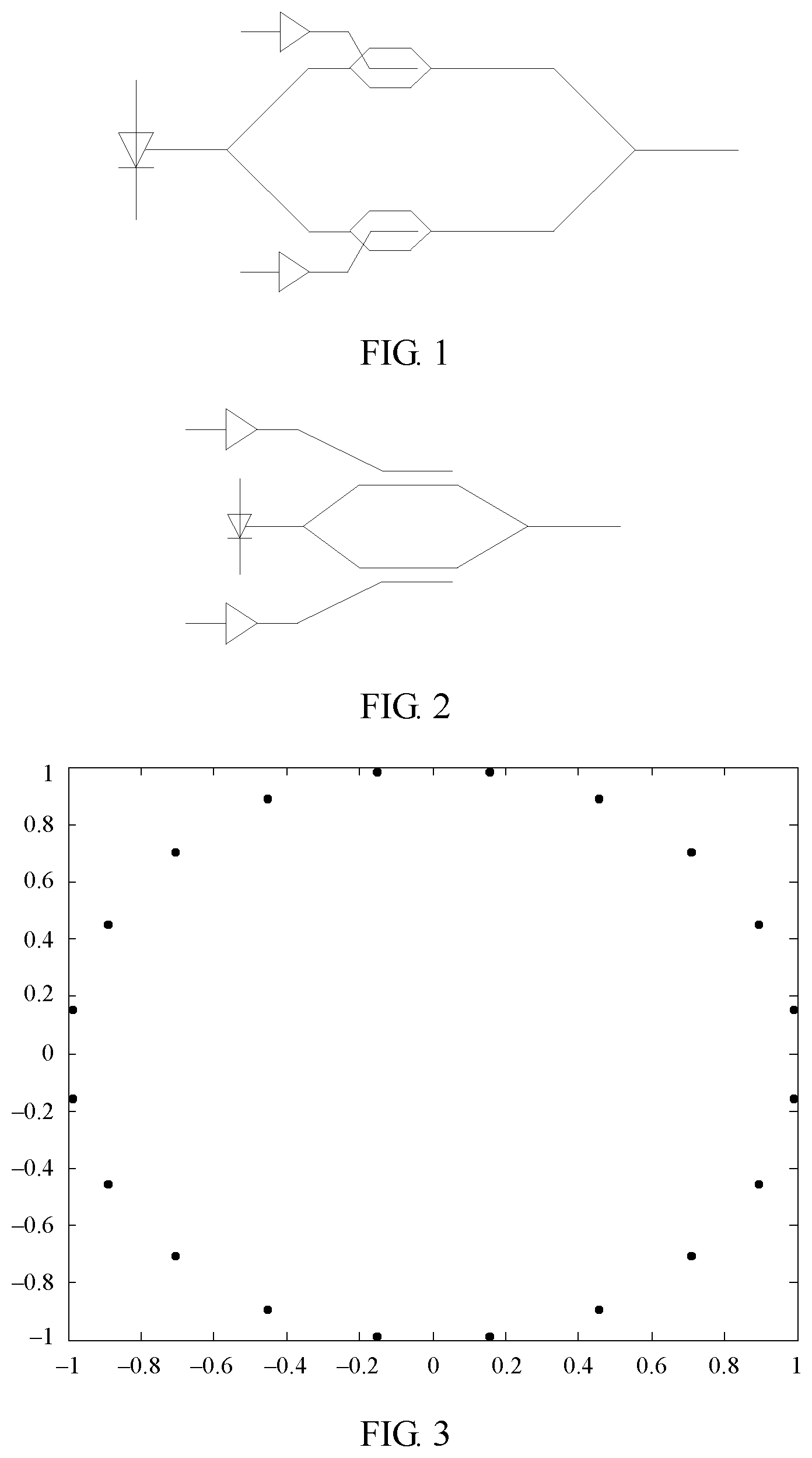
[0004] The 16 QAM is a higher order modulation technology, and spectral efficiency of the 16 QAM is four times that of a non-return to zero (NRZ) signal. In the 16 QAM, a dual-polarization inphase and quadrature Mach-Zehnder modulator (IQMZM) is usually used. FIG. 1 is a simple structural diagram of a typical IQMZM. The IQMZM includes two dual-drive Mach-Zehnder modulators (DDMZM). Phases of optical carrier signals of the two DDMZMs are different. One path of optical carrier signals are rotated by 90 degrees during output, and two paths of output signals are orthogonal to each other. FIG. 2 is a simple structural diagram of a typical DDMZM. Optical carrier signals are split into two paths at input ends, and two paths of optical signals respectively pass through an upper arm and a lower arm of the Mach-Zehnder modulator. The upper arm and the lower arm of the Mach-Zehnder modulator each are a phase modulator and each are controlled by one electrode. Two paths of optical carrier signals are combined into one path of signals at an output end for coherent output. When the two paths of optical signals have a same phase, an output signal has a maximum amplitude. When the two paths of optical signals have opposite phases, an output signal has a minimum amplitude.
[0005] FIG. 3 is a schematic diagram of representation of a phase of each arm of a DDMZM on a complex number plane. This is indicated by using the following formula:
Y n = exp ( j .pi. x n V pp + V biasn V .pi. ) . ##EQU00001##
[0006] Values of n are 1 and 2, respectively indicating an upper arm and a lower arm. Y.sub.n is output of a phase modulator on each arm, and is a complex number signal. x.sub.n is input of the phase modulator on each arm, V.sub.PP is an amplitude obtained after the input of the phase modulator is normalized, and V.sub.PP=1.5V.sub..pi.. V.sub.biasn is a bias voltage of a signal on each arm. V.sub..pi. is an intrinsic parameter of the DDMZM, and is usually a difference between a maximum value and a minimum value of an output amplitude of the DDMZM. In this way, output of the entire DDMZM may be indicated as follows:
Y = n = 1 2 Y n = exp ( j .pi. x 1 V p p + V bias 1 V .pi. ) + exp ( j .pi. - x 2 V p p + V bias 2 V .pi. ) . ##EQU00002##
[0007] The IQMZM has a congenital advantage of double spectral efficiency over 4 pulse amplitude modulation (4 Pulse Amplitude Modulation, 4 PAM) commonly used in short-distance metropolitan area transmission. However, in the short-distance metropolitan area transmission, transmission costs are a factor that needs to be considered. Costs of the IQMZM are excessively high, thereby affecting practicality of the IQMZM. At a current technical stage, the DDMZM has a great cost advantage over the IQMZM. If the DDMZM can be used to replace the IQMZM, great costs can be reduced.
[0008] However, it should be noted that, it is relatively easy to generate a modulation signal in a 16 QAM format in the IQMZM, but there are many problems in generating the modulation signal in the 16 QAM format in the DDMZM. In this way, a method for simply and effectively generating the modulation signal in the 16 QAM format in the DDMZM is particularly important.
[0009] In a related technology, two 16 PAM signals are used to drive the upper arm and the lower arm of the DDMZM. A complex plane modulation diagram of the upper arm is shown in FIG. 4, and a complex plane modulation diagram of the lower arm is shown in FIG. 5. In the technology, a signal is usually modulated at a null point, to be specific, a bias voltage of a modulator is 2V.sub..pi.N, where N is an integer. In this case, power occupied by an optical carrier signal is suppressed to a minimum, and this means that theoretical output signal power occupies 100% of total power, and modulation efficiency reaches a maximum.
[0010] Although in the technology, the modulation signal in the 16 QAM format can be successfully generated, a signal amplitude required by the technology is 1.9V.sub..pi.. In addition, because a 16-level drive signal is used in the technology, interference between signals may be very serious in a transmission process. It can be clearly seen from an eye diagram shown in FIG. 6 that a size of an "eye" is very small, and crosstalk between signals is very obvious.
SUMMARY
[0011] Embodiments of this disclosure provide a signal generation method and an electronic device, to resolve a problem of signal crosstalk. Technical solutions are as follows:
[0012] According to a first aspect, a signal generation method is provided, where the method includes: normalizing an I path of four-level signals and a Q path of four-level signals, to obtain a normalized I path of four-level signals and a normalized Q path of four-level signals; mapping the normalized I path of four-level signals and the normalized Q path of four-level signals based on a normalization coefficient, to obtain two paths of six-level signals, where the normalization coefficient is determined based on an actual value of a first path of level signals and a maximum value of the first path of level signals, and the first path of level signals are any path of level signals in the I path of four-level signals and the Q path of four-level signals; performing digital-to-analog conversion on the two paths of six-level signals to obtain converted signals; adjusting amplitudes of the converted signals to a preset amplitude, where the preset amplitude is less than a target amplitude, and the target amplitude is determined by a signal amplitude required when a 16-level signal drives a dual-drive Mach-Zehnder modulator DDMZM; and loading amplitude-adjusted signals to an upper arm and a lower arm of the DDMZM to generate modulation signals.
[0013] In the signal generation method, an output four-level signal is converted into a six-level signal, so that a requirement for driving the DDMZM to generate 16 QAM is met. In addition, a signal amplitude required to drive the DDMZM is reduced from 1.9V.sub..pi., to 1.275V.sub..pi.. In this way, two beneficial effects are achieved:
[0014] First, a quantity of levels of a drive signal is reduced, so that a signal-to-noise ratio requirement of a transmit end is reduced, crosstalk between signals is very small because there are a relatively small quantity of level signals, and clear eyes can be obtained from an eye diagram. In this way, a 16 QAM signal can also be successfully modulated even quality of an original signal at an input end is relatively poor.
[0015] Second, an amplitude requirement for the drive signal is greatly reduced, so that both power consumption pressure of a system and signal generation difficulty are reduced, and system performance is improved.
[0016] In a possible design, the I path of four-level signals and the Q path of four-level signals are signals obtained through Gray mapping, to improve data reliability of the signals.
[0017] In a possible design, the preset amplitude is 1.275V.sub..pi., and V.sub..pi. is a difference between a maximum value and a minimum value of an output signal amplitude of the DDMZM. Selection of the amplitude can reduce the amplitude requirement for the drive signal and obtain better signal quality.
[0018] In a possible design, the mapping the normalized I path of four-level signals and the normalized Q path of four-level signals based on a normalization coefficient, to obtain two paths of six-level signals includes: using a level value of the I path of signals in the normalized I path of four-level signals and the normalized Q path of four-level signals as a real part of a complex number, using a level value of the Q path of signals in the normalized I path of four-level signals and the normalized Q path of four-level signals as an imaginary part of the complex number, and processing the normalized I path of four-level signals and the normalized Q path of four-level signals based on the real part and the imaginary part of the complex number and the normalization coefficient, to obtain the two paths of six-level signals; or in another possible design, using a level value of the Q path of signals in the normalized I path of four-level signals and the normalized Q path of four-level signals as a real part of a complex number, using a level value of the I path of signals in the normalized I path of four-level signals and the normalized Q path of four-level signals as an imaginary part of the complex number, and processing the normalized I path of four-level signals and the normalized Q path of four-level signals based on the real part and the imaginary part of the complex number and the normalization coefficient, to obtain the two paths of six-level signals.
[0019] During processing, the normalized I path of four-level signals and the normalized Q path of four-level signals may be processed by using the following formulas, to obtain the two paths of six-level signals:
x=(-1-adj)(sig== -1a+ja)+(3-adj)(sig== 1a+ja)+(1+adj)(sig== 1a-ja)+(-3+adj)(sig== -1a-ja)+(1+adj)(sig== -3a+3ja)+(5+adj)(sig== 3a+3ja)+(-5-adj)(sig== 3a-3ja)+(-1-adj)(sig== -3a-3ja)+(1+adj)(sig== -1a+3ja)+(3-adj)(sig== 1a+3ja)+(-3+adj)(sig== 1a-3ja)+(-1-adj)(sig== -1a-3ja)+(5+adj)(sig== -3a+ja)+(-1-adj)(sig== 3a+ja)+(-5-adj)(sig== 3a-ja)+(1+adj)(sig== -3a-ja), and
y=(3-adj)(sig== -1a+ja)+(-1-adj)(sig== 1a+ja)+(-3+adj)(sig== 1a-ja)+(1+adj)(sig== -1a-ja)+(5+adj)(sig== -3a+3ja)+(1+adj)(sig== 3a+3ja)+(-1-adj)(sig== 3a-3ja)+(-5-adj)(sig== -3a-3ja)+(3-adj)(sig== -1a+3ja)+(1+adj)(sig== 1a+3ja)+(-1-adj)(sig== 1a-3ja)+(-3+adj)(sig== -1a-3ja)+(-1-adj)(sig== -3a+ja)+(5+adj)(sig== 3a+ja)+(1+adj)(sig== 3a-ja)+(-5-adj)(sig== -3a-ja),
where sig is the complex number; a is the normalization coefficient; a == operation is a comparison operation, and an operation rule is: when values on both sides of a symbol == are equal, an operation result is 1, and when values on both sides of the symbol == are unequal, an operation result is 0; and adj is a fine adjustment parameter.
[0020] When the I path of signals are used as the real part of the imaginary number and the Q path of signals are used as the imaginary part of the imaginary number, in the foregoing formulas, x is a signal output after the I path of signals are calculated by using a formula, and y is a signal output after the Q path of signals are calculated by using a formula.
[0021] When the Q path of signals are used as the real part of the imaginary number and the I path of signals are used as the imaginary part of the imaginary number, in the foregoing formulas, x is a signal output after the Q path of signals are calculated by using a formula, and y is a signal output after the I path of signals are calculated by using a formula.
[0022] According to a second aspect, an electronic device is provided, where the electronic device includes a normalization module, a mapping module, two digital-to-analog converters DACs, an amplitude adjustment module, and a DDMZM.
[0023] Two output ends of the normalization module are connected to two input ends of the mapping module, two output ends of the mapping module are respectively connected to input ends of the two DACs, output ends of the two DACs are connected to two input ends of the amplitude adjustment module, and two output ends of the amplitude adjustment module are connected to an upper arm and a lower arm of the DDMZM.
[0024] The normalization module receives an I path of four-level signals and a Q path of four-level signals, normalizes the I path of four-level signals and the Q path of four-level signals, and outputs normalized an I path of four-level signals and a Q path of four-level signals to the mapping module. The mapping module maps the normalized I path of four-level signals and the normalized Q path of four-level signals based on a normalization coefficient, and outputs two paths of six-level signals to the DAC module, where the normalization coefficient is determined based on an actual value of a first path of level signals and a maximum value of the first path of level signals, and the first path of level signals are any path of level signals in the I path of four-level signals and the Q path of four-level signals. The two DACs perform digital-to-analog conversion on the two paths of six-level signals to obtain converted signals. The amplitude adjustment module adjusts amplitudes of the converted signals to a preset amplitude, where the preset amplitude is less than a target amplitude, and the target amplitude is determined by a signal amplitude required when a 16-level signal drives a dual-drive Mach-Zehnder modulator DDMZM. The amplitude adjustment module loads amplitude-adjusted signals to an upper arm and a lower arm of the DDMZM to generate modulation signals. The electronic device further includes other components configured to implement functions in the first aspect.
BRIEF DESCRIPTION OF DRAWINGS
[0025] FIG. 1 is a simple structural diagram of a typical IQMZM;
[0026] FIG. 2 is a simple structural diagram of a typical DDMZM;
[0027] FIG. 3 is a schematic diagram of representation of a phase of each arm of a DDMZM on a complex number plane;
[0028] FIG. 4 is a complex plane modulation diagram of an upper arm of a DDMZM;
[0029] FIG. 5 is a complex plane modulation diagram of a lower arm of a DDMZM;
[0030] FIG. 6 is an eye diagram of a signal generated through modulation based on a 16-level drive signal;
[0031] FIG. 7 is a schematic system diagram of an optical fiber communications system;
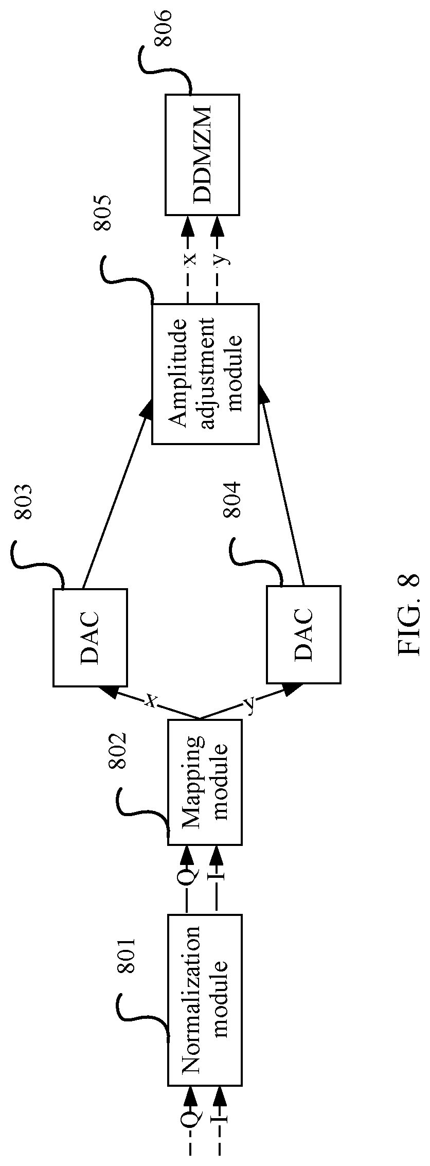
[0032] FIG. 8 is a schematic structural diagram of an electronic device according to another embodiment of this disclosure;
[0033] FIG. 9 is a schematic structural diagram of another electronic device according to another embodiment of this disclosure;
[0034] FIG. 10 is a flowchart of a signal generation method according to an embodiment of this disclosure;
[0035] FIG. 11 is an eye diagram corresponding to an x path of six-level signals and a y path of six-level signals;
[0036] FIG. 12 is a schematic diagram of mapping of an x path of six-level signals and a y path of six-level signals on a complex plane; and
[0037] FIG. 13 is a constellation diagram of a modulation signal in a 16 QAM format output in an embodiment of this disclosure.
DESCRIPTION OF EMBODIMENTS
[0038] To make the objectives, technical solutions, and advantages of this disclosure clearer, the following further describes the implementations of this disclosure in detail with reference to the accompanying drawings.
[0039] FIG. 7 is a schematic system diagram of an optical fiber communications system. The optical fiber communications system may include a transmitter and a receiver, and an optical fiber link configured to transmit a signal between the transmitter and the receiver. On a transmitter side, an electrical transmit end device may be further included, and the electrical transmit end device may provide a digital signal. The transmitter may receive the digital signal from the electrical transmit end device, perform channel coding, modulation, and the like on the digital signal, to obtain an optical signal, and transmit the optical signal to the receiver through the optical fiber link.
[0040] FIG. 8 is a schematic structural diagram of an electronic device according to another embodiment of this disclosure. Referring to FIG. 8, the electronic device includes a normalization module 801, a mapping module 802, two digital-to-analog converters DAC 803 and DAC 804, an amplitude adjustment module 805, and a DDMZM 806.
[0041] Two output ends of the normalization module 801 are connected to two input ends of the mapping module 802, two output ends of the mapping module 802 are respectively connected to input ends of the two DACs, output ends of the two DACs are connected to two input ends of the amplitude adjustment module, and two output ends of the amplitude adjustment module are connected to an upper arm and a lower arm of the DDMZM.
[0042] The normalization module 801 receives an I path of four-level signals and a Q path of four-level signals, normalizes the I path of four-level signals and the Q path of four-level signals, and outputs a normalized I path of four-level signals and a normalized Q path of four-level signals to the mapping module 802.
[0043] The mapping module 802 maps the normalized I path of four-level signals and the normalized Q path of four-level signals based on a normalization coefficient, and outputs two paths of six-level signals to the DAC module, where the normalization coefficient is determined based on an actual value of a first path of level signals and a maximum value of the first path of level signals, and the first path of level signals are any path of level signals in the I path of four-level signals and the Q path of four-level signals. The DAC 803 and the DAC 804 are respectively configured to perform digital-to-analog conversion on the two paths of six-level signals to obtain converted signals. The amplitude adjustment module adjusts amplitudes of the converted signals to a preset amplitude, where the preset amplitude is less than a target amplitude, and the target amplitude is determined by a signal amplitude required when a 16-level signal drives a dual-drive Mach-Zehnder modulator DDMZM. The amplitude adjustment module loads amplitude-adjusted signals to an upper arm and a lower arm of the DDMZM to generate modulation signals.
[0044] In a possible design, referring to FIG. 9, a Gray mapping module 800 may further be connected to an input end of the normalization module 801, and is configured to: perform Gray mapping on the original I path of four-level signals and Q path of four-level signals, and output a Gray-mapped I path of four-level signals and Q path of four-level signals to the normalization module 801.
[0045] In a possible design, the mapping module 802 includes a first complex number obtaining unit and a first calculation processing unit, and an output end of the first complex number obtaining unit is connected to an input end of the first calculation processing unit.
[0046] The first complex number obtaining unit uses a level value of the I path of signals in the normalized I path of four-level signals and the normalized Q path of four-level signals as a real part of a complex number, uses a level value of the Q path of signals in the normalized I path of four-level signals and the normalized Q path of four-level signals as an imaginary part of the complex number, to obtain the complex number corresponding to the normalized I path of four-level signals and the normalized Q path of four-level signals, and outputs the complex number to the first calculation processing unit.
[0047] The first calculation processing unit processes the normalized I path of four-level signals and the normalized Q path of four-level signals based on the real part and the imaginary part of the complex number and the normalization coefficient, to obtain the two paths of six-level signals.
[0048] In a possible design, the first calculation processing unit is configured to process the normalized I path of four-level signals and the normalized Q path of four-level signals based on the following formulas, to obtain the two paths of six-level signals:
x=(-1-adj)(sig== -1a+ja)+(3-adj)(sig== 1a+ja)+(1+adj)(sig== 1a-ja)+(-3+adj)(sig== -1a-ja)+(1+adj)(sig== -3a+3ja)+(5+adj)(sig== 3a+3ja)+(-5-adj)(sig== 3a-3ja)+(-1-adj)(sig== -3a-3ja)+(1+adj)(sig== -1a+3ja)+(3-adj)(sig== 1a+3ja)+(-3+adj)(sig== 1a-3ja)+(-1-adj)(sig== -1a-3ja)+(5+adj)(sig== -3a+ja)+(-1-adj)(sig== 3a+ja)+(-5-adj)(sig== 3a-ja)+(1+adj)(sig== -3a-ja), and
y=(3-adj)(sig== -1a+ja)+(-1-adj)(sig== 1a+ja)+(-3+adj)(sig== 1a-ja)+(1+adj)(sig== -1a-ja)+(5+adj)(sig== -3a+3ja)+(1+adj)(sig== 3a+3ja)+(-1-adj)(sig== 3a-3ja)+(-5-adj)(sig== -3a-3ja)+(3-adj)(sig== -1a+3ja)+(1+adj)(sig== 1a+3ja)+(-1-adj)(sig== 1a-3ja)+(-3+adj)(sig== -1a-3ja)+(-1-adj)(sig== -3a+ja)+(5+adj)(sig== 3a+ja)+(1+adj)(sig== 3a-ja)+(-5-adj)(sig== -3a-ja),
where sig is the complex number; a is the normalization coefficient; a == operation is a comparison operation, and an operation rule is: when values on both sides of a symbol == are equal, an operation result is 1, and when values on both sides of the symbol == are unequal, an operation result is 0; adj is a fine adjustment parameter; x is a signal output after the I path of signals are calculated by using a formula; and y is a signal output after the Q path of signals are calculated by using a formula.
[0049] In a possible design, the mapping module 802 includes a second complex number obtaining unit and a second calculation processing unit, and an output end of the second complex number obtaining unit is connected to an input end of the second calculation processing unit.
[0050] The second complex number obtaining unit uses a level value of the Q path of signals in the normalized I path of four-level signals and the normalized Q path of four-level signals as a real part of a complex number, uses a level value of the I path of signals in the normalized I path of four-level signals and the normalized Q path of four-level signals as an imaginary part of the complex number, to obtain the complex number corresponding to the normalized I path of four-level signals and the normalized Q path of four-level signals, and outputs the complex number to the second calculation processing unit.
[0051] The second calculation processing unit processes the normalized I path of four-level signals and the normalized Q path of four-level signals based on the real part and the imaginary part of the complex number and the normalization coefficient, to obtain the two paths of six-level signals.
[0052] In a possible design, the second calculation processing unit is configured to process the normalized I path of four-level signals and the normalized Q path of four-level signals based on the following formulas, to obtain the two paths of six-level signals:
x=(-1-adj)(sig== -1a+ja)+(3-adj)(sig== 1a+ja)+(1+adj)(sig== 1a-ja)+(-3+adj)(sig== -1a-ja)+(1+adj)(sig== -3a+3ja)+(5+adj)(sig== 3a+3ja)+(-5-adj)(sig== 3a-3ja)+(-1-adj)(sig== -3a-3ja)+(1+adj)(sig== -1a+3ja)+(3-adj)(sig== 1a+3ja)+(-3+adj)(sig== 1a-3ja)+(-1-adj)(sig== -1a-3ja)+(5+adj)(sig== -3a+ja)+(-1-adj)(sig== 3a+ja)+(-5-adj)(sig== 3a-ja)+(1+adj)(sig== -3a-ja), and
y=(3-adj)(sig== -1a+ja)+(-1-adj)(sig== 1a+ja)+(-3+adj)(sig== 1a-ja)+(1+adj)(sig== -1a-ja)+(5+adj)(sig== -3a+3ja)+(1+adj)(sig== 3a+3ja)+(-1-adj)(sig== 3a-3ja)+(-5-adj)(sig== -3a-3ja)+(3-adj)(sig== -1a+3ja)+(1+adj)(sig== 1a+3ja)+(-1-adj)(sig== 1a-3ja)+(-3+adj)(sig== -1a-3ja)+(-1-adj)(sig== -3a+ja)+(5+adj)(sig== 3a+ja)+(1+adj)(sig== 3a-ja)+(-5-adj)(sig== -3a-ja)
where sig is the complex number; a is the normalization coefficient; a == operation is a comparison operation, and an operation rule is: when values on both sides of a symbol == are equal, an operation result is 1, and when values on both sides of the symbol == are unequal, an operation result is 0; adj is a fine adjustment parameter; x is a signal output after the Q path of signals are calculated by using a formula; and y is a signal output after the I path of signals are calculated by using a formula.
[0053] FIG. 10 is a flowchart of a signal generation method according to an embodiment of this disclosure. The signal generation method may be performed by an electronic device. Referring to FIG. 10, the method includes the following steps.
[0054] 1001. Perform Gray mapping on an original I path of four-level signals and Q path of four-level signals to obtain an I path of four-level signals and a Q path of four-level signals.
[0055] The I path of four-level signals and the Q path of four-level signals may be quadrature signals that are generated by a signal source component of a transmitter and whose phase difference is 90 degrees. A signal input end is connected to an input end of a Gray mapping module, the I path of four-level signals and the Q path of four-level signals are input to the Gray mapping module for Gray mapping, and the I path of four-level signals and the Q path of four-level signals are output through two output ends of the Gray mapping module. The Gray mapping is a data conversion manner. In a Gray mapping process, Gray coding conversion is performed on original signal data, and adjacent numbers differ by only one bit in signals obtained after the Gray coding conversion. In cases of a signal transmission loss, attenuation, noise interference, signal crosstalk, and the like, only one bit of data is lost each time one number is lost. In this way, even if a bit error, a data packet loss, or a loss occurs in a data transmission process, data obtained through Gray coding mapping conversion can also ensure a minimum loss rate of the data.
[0056] Certainly, in this embodiment of this disclosure, alternatively, the Gray mapping may not be performed, but normalization processing in step 1002 is directly performed, to reduce a transmitter component, so that processing efficiency in a signal transmission process can be improved.
[0057] 1002. Normalize the I path of four-level signals and the Q path of four-level signals, to obtain a normalized I path of four-level signals and a normalized Q path of four-level signals.
[0058] An output end of the Gray mapping module is connected to an input end of a normalization module. After the Gray mapping, the Gray mapping module outputs the I path of four-level signals and the Q path of four-level signals to the normalization module for normalization processing. After the normalization processing, levels of the I path of four-level signals and the Q path of four-level signals are adjusted to four levels: [-3.sup.a, -1.sup.a, 1.sup.a, 3.sup.a] for output. In a normalization process, a normalization coefficient may be determined. To be specific, the normalization coefficient is determined based on an actual value of a first path of level signals and a maximum value of the first path of level signals, and the first path of level signals are any path of level signals in the I path of four-level signals and the Q path of four-level signals.
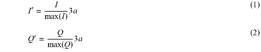
[0059] The normalization process is a mathematical conversion process, and the following formula (1) and formula (2) may be used in a specific conversion process:
I ' = I max ( I ) 3 a ( 1 ) Q ' = Q max ( Q ) 3 a ( 2 ) ##EQU00003##
[0060] max(I) is a maximum level value of the I path of signals, max(Q) is a maximum level value of the Q path of signals, I' is a level value of a normalized I path of signals output in real time, Q' is a level value of a normalized Q path of signals output in real time, and a is the normalization coefficient.
[0061] 1003. Map the normalized I path of four-level signals and the normalized Q path of four-level signals based on a normalization coefficient, to obtain two paths of six-level signals.
[0062] Two output ends of the normalization module are connected to two input ends of a mapping module. The mapping module maps the I path of four-level signals and the Q path of four-level signals obtained after the normalization processing, and outputs the two paths of six-level signals. A mapping process is performed based on the normalization coefficient, and may specifically include the following process:
[0063] First, a complex number corresponding to the I path of four-level signals and the Q path of four-level signals is generated based on the input I path of four-level signals and Q path of four-level signals.
[0064] In a possible design, an input level value of the I path of signals at a particular moment is used as a real part of the complex number, and an input level value of the Q path of signals at the same moment is used as an imaginary part of the complex number, to construct the complex number that includes values of the I path of four-level signals and the Q path of four-level signals based on the moment. Specifically, the complex number is indicated by using a formula: sig=I+jQ, and sig is the complex number corresponding to the I path of four-level signals and the Q path of four-level signals at the particular moment.
[0065] In another possible design, an input level value of the Q path of signals at a particular moment is used as a real part of the complex number, and an input level value of the I path of signals at the same moment is used as an imaginary part of the complex number, to construct the complex number that includes values of the I path of four-level signals and the Q path of four-level signals based on the moment. Specifically, the complex number is indicated by using a formula: sig=Q+jI, and sig is the complex number corresponding to the I path of four-level signals and the Q path of four-level signals at the particular moment.
[0066] In a conventional method for generating a modulation signal in a 16 QAM format, signals in the 16 QAM format are mapped on a complex plane to generate a constellation diagram. When moduli of signals corresponding to points on four vertex angles in the constellation diagram are a possible maximum modulation amplitude of a DDMZM, 16 level values are required by drive signals for an upper arm and a lower arm of the DDMZM. Therefore, a 16-level input signal is used to drive the DDMZM to generate the modulation signal in the 16 QAM format. During an experiment, an inventor finds that when a modulus of each point in the constellation diagram is reduced, in other words, when a modulation amplitude of a signal is reduced, a quantity of 16 level values required by the drive signal is reduced, and sizes of 16 level values even overlap. 16 levels may be reduced to six levels in a process of reducing an amplitude of the modulation signal. The inventor realizes that this is a feasible method for generating the modulation signal in the 16 QAM format by using fewer than 16 levels. Based on this phenomenon, this disclosure proposes a conversion formula for converting four levels to six levels, and the normalized I path of four-level signals and the normalized Q path of four-level signals may be processed based on the real part and the imaginary part of the complex number and the normalization coefficient by using the conversion formula, to obtain the two paths of six-level signals, and further drive, by using a six-level signal, the DDMZM to generate the modulation signal in the 16 QAM format.
[0067] The foregoing process is specifically indicated by using the following formula (3) and formula (4):
x=(-1-adj)(sig== -1a+ja)+(3-adj)(sig== 1a+ja)+(1+adj)(sig== 1a-ja)+(-3+adj)(sig== -1a-ja)+(1+adj)(sig== -3a+3ja)+(5+adj)(sig== 3a+3ja)+(-5-adj)(sig== 3a-3ja)+(-1-adj)(sig== -3a-3ja)+(1+adj)(sig== -1a+3ja)+(3-adj)(sig== 1a+3ja)+(-3+adj)(sig== 1a-3ja)+(-1-adj)(sig== -1a-3ja)+(5+adj)(sig== -3a+ja)+(-1-adj)(sig== 3a+ja)+(-5-adj)(sig== 3a-ja)+(1+adj)(sig== -3a-ja) (3)
y=(3-adj)(sig== -1a+ja)+(-1-adj)(sig== 1a+ja)+(-3+adj)(sig== 1a-ja)+(1+adj)(sig== -1a-ja)+(5+adj)(sig== -3a+3ja)+(1+adj)(sig== 3a+3ja)+(-1-adj)(sig== 3a-3ja)+(-5-adj)(sig== -3a-3ja)+(3-adj)(sig== -1a+3ja)+(1+adj)(sig== 1a+3ja)+(-1-adj)(sig== 1a-3ja)+(-3+adj)(sig== -1a-3ja)+(-1-adj)(sig== -3a+ja)+(5+adj)(sig== 3a+ja)+(1+adj)(sig== 3a-ja)+(-5-adj)(sig== -3a-ja) (4)
[0068] In the formulas, sig is the complex number corresponding to the I paths of signals and the Q path of signals at a particular moment; a is the determined normalization coefficient; a == operation is a comparison operation, and an operation rule is: when values on both sides of a symbol == are equal, an operation result is 1, and when values on both sides of the symbol == are unequal, an operation result is 0; and adj is a fine adjustment parameter. In actual calculation, an optimal value is 0.2. x is a signal output after the I path of signals are calculated by using a formula, and y is a signal output after the Q path of signals are calculated by using a formula.
[0069] In another possible design, a level value of the Q path of signals in the normalized I path of four-level signals and the normalized Q path of four-level signals may be alternatively used as a real part of a complex number, a level value of the I path of signals in the normalized I path of four-level signals and the normalized Q path of four-level signals is used as an imaginary part of the complex number, and the normalized I path of four-level signals and the normalized Q path of four-level signals are processed based on the real part and the imaginary part of the complex number and the normalization coefficient, to obtain the two paths of six-level signals. In this case, the foregoing formula (3) and formula (4) may still be used for processing. However, because values of the imaginary part and the real part change, indications of parameters of the formulas change. In this possible design, x is a signal output after the Q path of signals are calculated by using a formula, and y is a signal output after the I path of signals are calculated by using a formula.
[0070] It can be clearly learned from the foregoing formulas that the complex number corresponding to the I path of signals and the Q path of signals at a particular moment is a fixed value sig. In this way, for the particular moment, only one comparison operation in the foregoing formulas is equal, and has an operation result of 1, and all remaining operation results are 0. Considering impact from the fine adjustment parameter, a finally output level value is only one of -5.2.sup.a, -2.8.sup.a, -1.2.sup.a, 1.2.sup.a, 2.8.sup.a, and 5.2.sup.a. In this way, the input I path of four-level signals and Q path of four-level signals [-3.sup.a, -1.sup.a, 1.sup.a, 3.sup.a] are successfully converted into an x path of six-level signals and a y path of six-level signals [-5.2.sup.a, -2.8.sup.a, -1.2.sup.a, 1.2.sup.a, 2.8.sup.a, 5.2.sup.a]. An eye diagram corresponding to the x path of six-level signals and the y path of six-level signals is shown in FIG. 11. An "eye" can be clearly seen from the eye diagram, and this means that crosstalk between signals is relatively small. Mapping of the x path of six-level signals and the y path of six-level signals on a complex plane is shown in FIG. 12.
[0071] 1004. Perform digital-to-analog conversion on the two paths of six-level signals by using digital-to-analog converters DACs, to obtain converted signals.
[0072] The two output ends of the mapping module are respectively connected to input ends of the DACs, the x path of six-level signals and the y path of six-level signals [-5.2.sup.a, -2.8.sup.a, -1.2.sup.a, 1.2.sup.a, 2.8.sup.a, 5.2.sup.a] are output to the DACs for signal conversion, and an x path of digital signals and a y path of digital signals are converted to an x path of analog signals and a y path of analog signals and are output.
[0073] 1005. Adjust amplitudes of the converted signals to 1.275 V.sub..pi., where V.sub..pi. is a difference between a maximum value and a minimum value of an output amplitude of a DDMZM.
[0074] Output ends of the DACs are connected to two input ends of an amplitude adjustment module. After the converted signals are input to the amplitude adjustment module, the converted signals are adjusted to 1.275 V.sup..pi. through amplitude adjustment and are output. In this embodiment of this disclosure, the amplitude may be adjusted to a preset amplitude, the preset amplitude is less than a target amplitude, and the target amplitude is determined by a signal amplitude required when a 16-level signal drives the dual-drive Mach-Zehnder modulator DDMZM. For example, the preset amplitude is 1.275 V.sub..pi., and V.sub..pi. is the difference between the maximum value and the minimum value of the output amplitude of the DDMZM, in other words, a voltage difference between the upper arm and the lower arm of the DDMZM when direct current light intensity of the DDMZM changes from maximum output to minimum output.
[0075] 1006. Load amplitude-adjusted signals to the upper arm and the lower arm of the DDMZM to generate modulation signals.
[0076] Two output ends of the amplitude adjustment module are connected to the upper arm and the lower arm of the DDMZM. After amplitudes of the x path of analog signals and the y path of analog signals are adjusted, the amplitude adjustment module respectively loads the two paths of analog signals to the upper arm and the lower arm of the DDMZM to drive the DDMZM. The upper arm and the lower arm of the DDMZM are two optical tributaries, an electro-optic polarity material is used for each optical tributary, and a refractive index of the optical tributary changes with a magnitude of an externally applied electrical signal. A change in the refractive index of the optical tributary causes a change in a signal phase. When signals of the two optical tributaries are combined at an output end again, a combined optical signal is an interference signal whose intensity varies with time, and this is equivalent to that a change in an electrical signal is converted to a change in an optical signal, thereby implementing light intensity modulation.
[0077] A modulation point of the DDMZM is set to a null point, to be specific, a bias voltage of the modulator is 2V.sub..pi.N, where N is a positive integer. When the DDMZM works at the null point, power occupied by a direct current light is suppressed to a minimum, in other words, a carrier signal power ratio (Carrier Signal Power Ratio, CSPR) is suppressed to a minimum. The DDMZM generates and outputs the modulation signal in the 16 QAM format in a working process. A constellation diagram of the modulation signal in the 16 QAM format output in this embodiment of this disclosure is shown in FIG. 13.
[0078] According to the method provided in this embodiment of this disclosure, a mapping process is increased in this disclosure, to convert a four-level signal into a six-level signal, so that the dual-drive Mach-Zehnder modulator DDMZM is driven based on the six-level signal, thereby reducing a signal-to-noise ratio requirement of an input signal, improving a noise resistance capability of a transmit end, reducing impact from crosstalk between signals, and reducing a requirement standard on components such as the DAC and a driver. In addition, in this embodiment of this disclosure, an amplitude requirement of the drive signal is greatly reduced, so that the amplitude requirement of the drive signal is reduced, and a power consumption requirement is further reduced, thereby reducing working pressure of the DDMZM, and improving overall system performance. Further, the Gray mapping may be performed on the original input I path of four-level signals and Q path of four-level signals, to improve data reliability. In addition, in this embodiment of this disclosure, an amplitude of the drive signal is further reduced to 1.275V.sub..pi., and the power consumption requirement is further reduced.
[0079] All the foregoing optional technical solutions may be randomly combined to form optional embodiments of this disclosure, and details are not described herein.
* * * * *
D00000
D00001
D00002
D00003
D00004
D00005
D00006
D00007
D00008
XML
uspto.report is an independent third-party trademark research tool that is not affiliated, endorsed, or sponsored by the United States Patent and Trademark Office (USPTO) or any other governmental organization. The information provided by uspto.report is based on publicly available data at the time of writing and is intended for informational purposes only.
While we strive to provide accurate and up-to-date information, we do not guarantee the accuracy, completeness, reliability, or suitability of the information displayed on this site. The use of this site is at your own risk. Any reliance you place on such information is therefore strictly at your own risk.
All official trademark data, including owner information, should be verified by visiting the official USPTO website at www.uspto.gov. This site is not intended to replace professional legal advice and should not be used as a substitute for consulting with a legal professional who is knowledgeable about trademark law.