Cooling Member And Power Storage Module
Kind Code
U.S. patent application number 15/776211 was filed with the patent office on 2020-08-06 for cooling member and power storage module. The applicant listed for this patent is AUTONETWORKS TECHNOLOGIES, LTD. SUMITOMO WIRING SYSTEMS, LTD. SUMITOMO ELECTRIC INDUSTRIES, LTD.. Invention is credited to Makoto HIGASHIKOZONO, Hiroki HIRAI, Yoshiyuki HIROSE, Akihisa HOSOE, Hideyuki KUBOKI, Tomoharu TAKEYAMA.
| Application Number | 20200251790 15/776211 |
| Document ID | / |
| Family ID | 1000004813547 |
| Filed Date | 2020-08-06 |


View All Diagrams
| United States Patent Application | 20200251790 |
| Kind Code | A1 |
| KUBOKI; Hideyuki ; et al. | August 6, 2020 |
COOLING MEMBER AND POWER STORAGE MODULE
Abstract
A cooling member includes refrigerant, an absorbing member absorbing the refrigerant, an enclosing member including flexible sheet members, that are connected to each other and enclosing the refrigerant and the absorbing member in a sealed state, and a heat releasing section configured to receive heat from the enclosing member and release the heat to an outside.
| Inventors: | KUBOKI; Hideyuki; (Yokkaichi-shi, Mie, JP) ; HIRAI; Hiroki; (Yokkaichi-shi, Mie, JP) ; HIGASHIKOZONO; Makoto; (Yokkaichi-shi, Mie, JP) ; HOSOE; Akihisa; (Osaka-shi, Osaka, JP) ; TAKEYAMA; Tomoharu; (Osaka-shi, Osaka, JP) ; HIROSE; Yoshiyuki; (Osaka-shi, Osaka, JP) | ||||||||||
| Applicant: |
|
||||||||||
|---|---|---|---|---|---|---|---|---|---|---|---|
| Family ID: | 1000004813547 | ||||||||||
| Appl. No.: | 15/776211 | ||||||||||
| Filed: | December 1, 2016 | ||||||||||
| PCT Filed: | December 1, 2016 | ||||||||||
| PCT NO: | PCT/JP2016/085681 | ||||||||||
| 371 Date: | May 15, 2018 |
| Current U.S. Class: | 1/1 |
| Current CPC Class: | H01M 10/653 20150401; H01M 10/613 20150401; H01M 10/6567 20150401; H01M 10/6569 20150401 |
| International Class: | H01M 10/613 20060101 H01M010/613; H01M 10/653 20060101 H01M010/653; H01M 10/6567 20060101 H01M010/6567; H01M 10/6569 20060101 H01M010/6569 |
Foreign Application Data
| Date | Code | Application Number |
|---|---|---|
| Dec 2, 2015 | JP | 2015-235679 |
Claims
1. A cooling member comprising: refrigerant that changes between gas and fluid; an absorbing member absorbing the refrigerant; an enclosing member including flexible sheet members that are connected to each other and configured to enclose the refrigerant and the absorbing member in a sealed state; and a heat releasing section configured to receive heat from the enclosing member and release the heat to an outside, wherein the heat releasing section includes a recessed section in which an end portion of the enclosing member is inserted and having opposing walls, and a distance between the opposing walls of the recessed section is greater than a thickness of the enclosing member having a low inner pressure, and the flexible sheet members are in contact with the recessed section when the inner pressure of the enclosing member is increased and the enclosing member is expanded according to vaporization of the refrigerant.
2. (canceled)
3. The cooling member according to claim 1, wherein the heat releasing section releases heat to an outside via circulation of gas or fluid.
4. A power storage module comprising: the cooling member according to claim 1; and a power storage element having an outer surface, wherein at least a part of the outer surface is in contact with the cooling member.
5. The power storage module according to claim 4, further comprising a casing in which the power storage element is arranged and having an inner surface that is in contact with the outer surface of the power storage element, wherein the heat releasing section is included in the casing.
6. The power storage module according to claim 4, further comprising a pair of holding plates that hold the power storage element therebetween while being in contact with the outer surface of the power storage element, and the pair of holding plates being in contact with the heat releasing section.
Description
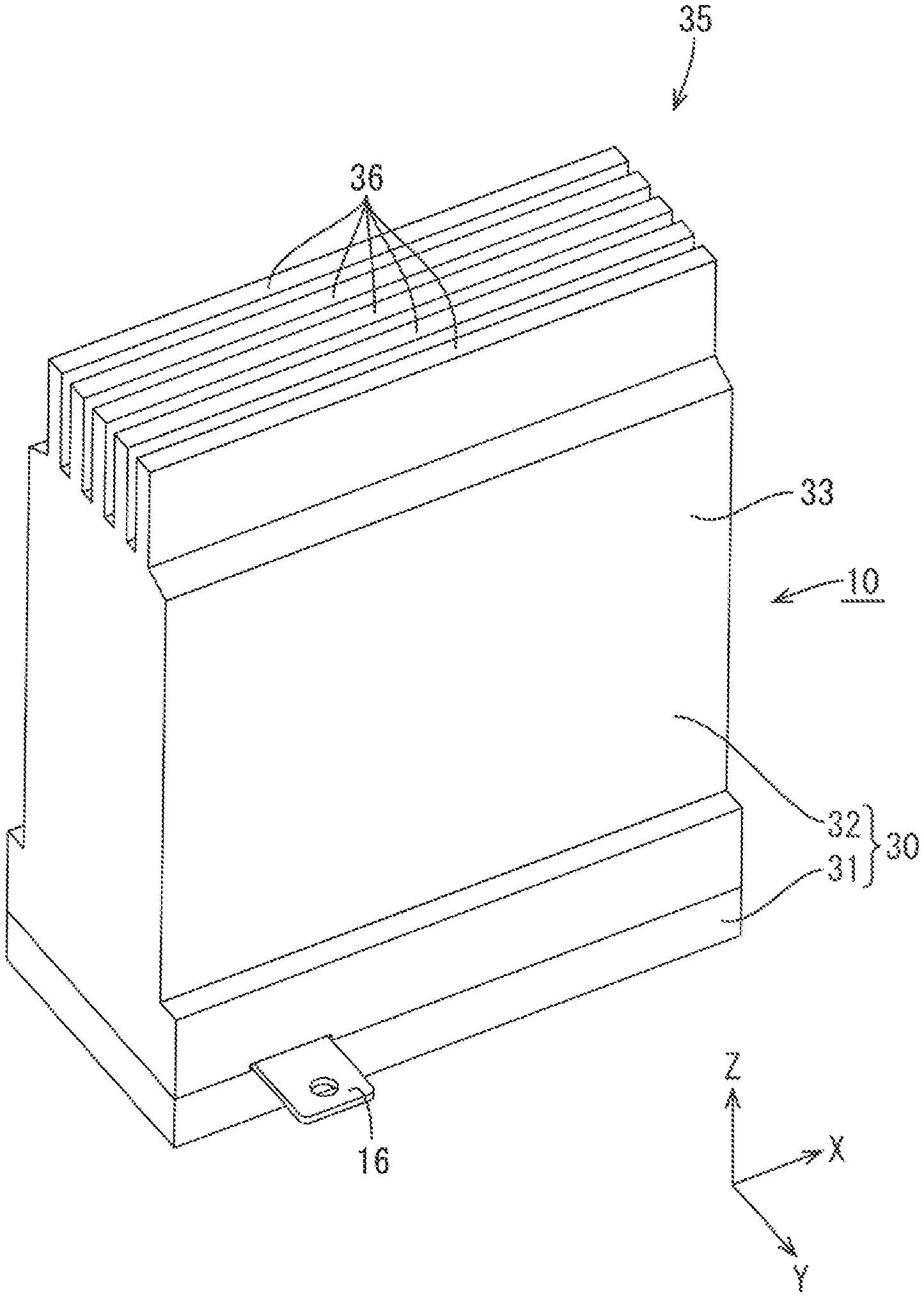
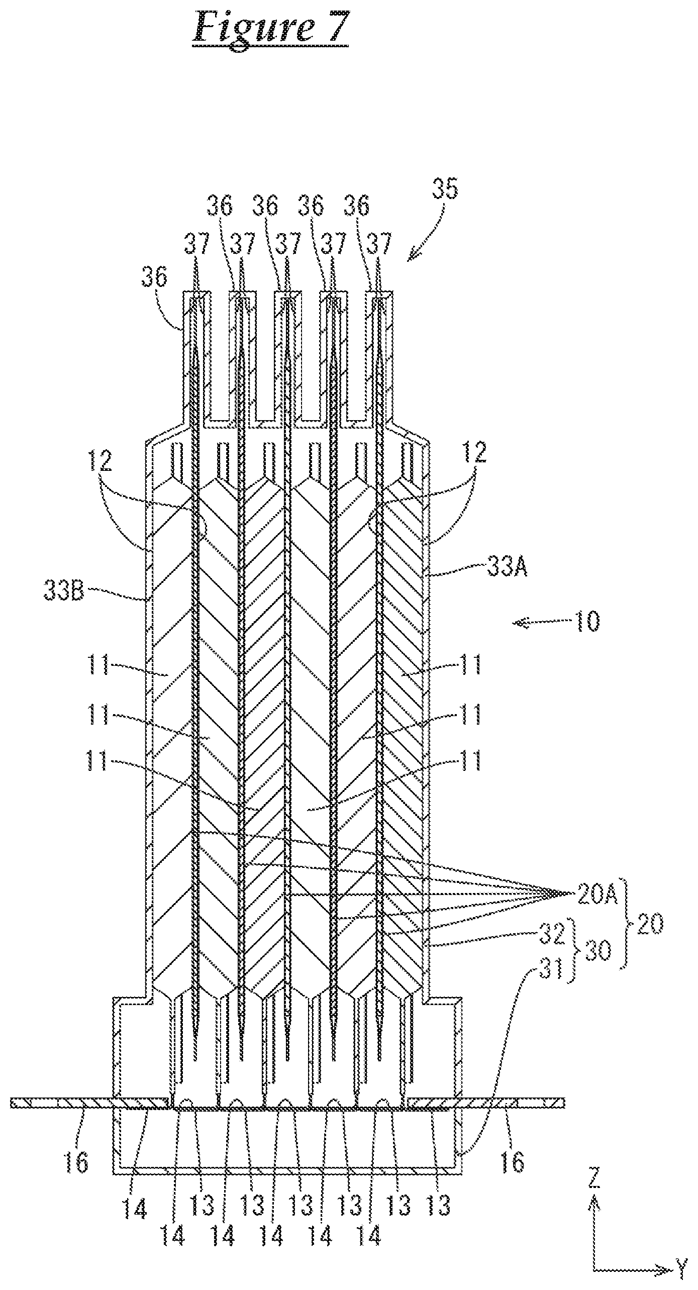
CROSS REFERENCE TO RELATED APPLICATIONS
[0001] This application claims the priority of Japanese patent application JP2015-235679 filed on Dec. 2, 2015, the entire contents of which are incorporated herein.
TECHNICAL FIELD
[0002] The present technology relates to a cooling member and a power storage module.
BACKGROUND ART
[0003] A heat pipe described in Patent Document 1 has been known. Such a heat pipe includes a pipe made of metal and heat transfer fluid filled in the heat pipe in a fluid tight manner.
[0004] [Patent Document 1] Japanese Unexamined Patent Application Publication No. 11-23169
SUMMARY
[0005] According to the above structure, the pipe needs to be strong to seal the heat transfer fluid therein because the heat transfer fluid that receives heat from a heating element is evaporated and increases its volume and pressure within the pipe is increased. If the pipe that is relatively strong and encloses the heat transfer fluid therein in a fluid tight manner is used, a manufacturing cost may be increased.
[0006] The present technology described in this specification has been completed in view of the circumstances described above. It is an object of the present technology to reduce a manufacturing cost of a cooling member.
[0007] A cooling member according to the description in this specification includes refrigerant, an absorbing member absorbing the refrigerant, an enclosing member including flexible sheet members that are connected to each other and configured to enclose the refrigerant and the absorbing member in a sealed state, and a heat releasing section configured to receive heat from the enclosing member and release the heat to an outside.
[0008] According to such a configuration, the pressure inside the enclosing member is increased by the evaporation of the refrigerant. Then, the flexible sheet members are deformed to increase the volume of the enclosing member and the pressure within the enclosing member is lowered. Accordingly, pressure resistance of the enclosing member can be lowered compared to the cooling member of a metal container that does not change its volume. Therefore, a manufacturing cost of the cooling member is reduced. The heat of the enclosing member is released outside via the heat releasing section, and the heat releasing properties can be improved.
[0009] Following configurations may be preferable for embodiments of the technology described in this specification.
[0010] The heat releasing section may include a recessed section in which an end portion of the enclosing member is inserted.
[0011] According to such a configuration, inner wall surfaces of the recessed section of the heat releasing section are opposite outer surfaces of the end portion of the enclosing member such that an area of the heat releasing section receiving the heat from the enclosing member is increased. This improves heat releasing properties.
[0012] The heat releasing section may release heat to an outside via circulation of gas or fluid.
[0013] Accordingly, the heat releasing properties of the heat releasing section can be improved.
[0014] A power storage module may include the cooling member and a power storage element having an outer surface, and at least a part of the outer surface may be in contact with the cooling member.
[0015] According to such a configuration, heat of the power storage element can be released via the heat releasing section.
[0016] The power storage module may further include a casing in which the power storage element is arranged and having an inner surface that is in contact with the outer surface of the power storage element, and the heat releasing section may be included in the casing.
[0017] According to such a configuration, heat of the power storage element can be released via the casing.
[0018] The power storage module may further include a pair of holding plates that hold the power storage element therebetween while being in contact with the outer surface of the power storage element, and the pair of holding plates may be in contact with the heat releasing section.
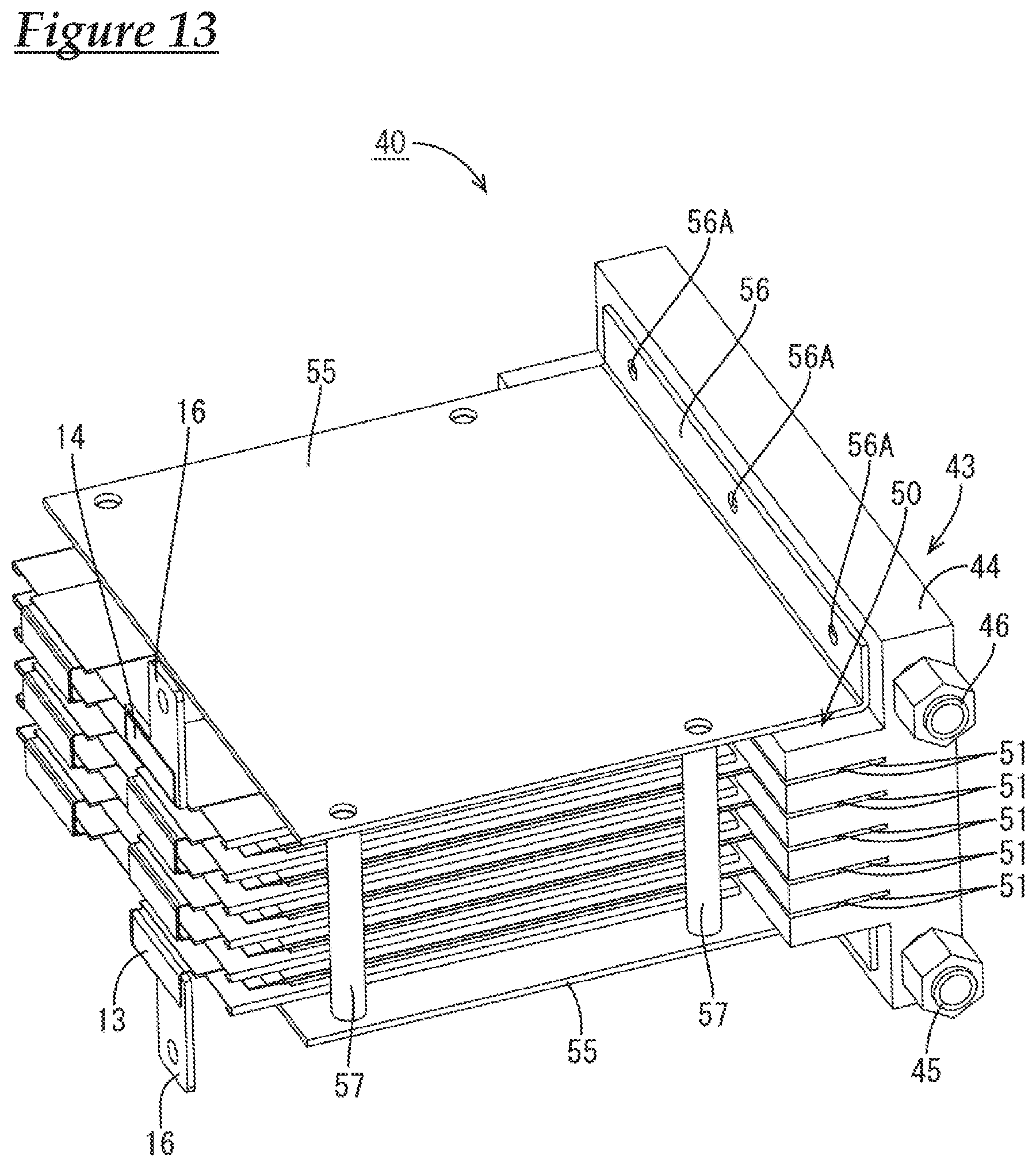
[0019] According to such a configuration, heat of the power storage element can be released via the holding plates.
[0020] According to the present technology, a manufacturing cost of a cooling member is reduced.
BRIEF DESCRIPTION OF THE DRAWINGS
[0021] FIG. 1 is a perspective view illustrating a power storage module according to a first embodiment.
[0022] FIG. 2 is a plan view illustrating the power storage module.
[0023] FIG. 3 is a front view illustrating the power storage module.
[0024] FIG. 4 is a cross-sectional view taken along line A-A in FIG. 3.
[0025] FIG. 5 is an enlarged view illustrating a part of FIG. 4.
[0026] FIG. 6 is a cross-sectional view taken along line B-B in FIG. 3.
[0027] FIG. 7 is a cross-sectional view taken along line C-C in FIG. 3.
[0028] FIG. 8 is a side view illustrating the power storage module.
[0029] FIG. 9 is an exploded perspective view of the power storage module.
[0030] FIG. 10 is a front view illustrating a power storage element group.
[0031] FIG. 11 is a perspective view illustrating a heat transfer pack.
[0032] FIG. 12 is an exploded perspective view of the heat transfer pack.
[0033] FIG. 13 is a perspective view illustrating a power storage module according to a second embodiment.
[0034] FIG. 14 is a plan view illustrating the power storage module.
[0035] FIG. 15 is a cross-sectional view taken along line D-D in FIG. 14.
[0036] FIG. 16 is a front view illustrating the power storage module.
[0037] FIG. 17 is a side view illustrating the power storage module.
[0038] FIG. 18 is a rear view illustrating the power storage module.
DESCRIPTION
First Embodiment
[0039] One embodiment will be described with reference to FIGS. 1 to 12.
[0040] As illustrated in FIG. 7, a power storage module 10 according to this embodiment includes power storage elements 11 (six in this embodiment) and a cooling member 20 that cools the power storage elements 11. In following description, an X direction represents a front side and a Z direction represents an upper side.
[0041] The power storage elements 11 are arranged in a row along a small thickness direction of the power storage element 11. Each of the power storage elements 11 includes a pair of laminating sheets 12 and a power storage component that is disposed between the laminating sheets 12, and end sections of the laminating sheets 12 are bonded in a liquid tight manner with a known method such as heat-welding. Positive terminals 13 and negative terminals 14 that are formed from a thin metal foil extend from a lower end of each power storage element 11 while being in contact with inner surfaces of the laminating sheets 12 in a liquid tight manner. The positive terminal 13 and the negative terminal 14 extend from an inside to an outside of the laminating sheet 12. The positive terminals 13 and the negative terminals 14 are electrically connected to the power storage components inside the power storage elements 11, respectively.
[0042] The adjacent power storage elements 11 are arranged in an opposite oriented manner. The positive terminal 13 and the negative terminal 14 of the adjacent storage elements 11 are bent to be closer to each other and ovelapped with each other and the overlapped positive terminal 13 and negative terminal 14 are electrically connected to each other with a known method such as laser welding, ultrasonic welding, and brazing. Thus, the power storage elements 11 are connected in series.
[0043] In this embodiment, secondary batteries such as lithium ion secondary batteries and nickel hydride batteries or capacitors such as electric double layer capacitors and lithium ion capacitors may be used as the power storage elements 11, and any power storage elements 11 can be used as appropriate. Ends of the positive terminals 13 and the negative terminals 14 that are connected in series are connected to power terminals 16 that are formed from a metal plate with a known method such as laser welding, ultrasonic welding, and brazing.
[0044] The cooling member 20 includes heat transfer packs 20A (five in this embodiment) and a casing 30. The heat transfer packs 20A receive heat from the power storage elements 11 and the casing 30 includes a heat releasing section 35 that receives the heat from the heat transfer packs 20A and releases the heat outside the casing 30.
[0045] The heat transfer packs 20A have a same configuration and each of the heat transfer packs 20A is between the adjacent power storage elements 11 while being closely in contact with each other. As illustrated in FIG. 12, the heat transfer pack 20A includes refrigerant 21 that changes between fluid and gas, an enclosing member 22 that is formed in a liquid tight manner and the refrigerant 21 is enclosed inside the enclosing member 22, and an absorbing member 26 that is disposed inside the enclosing member 22 and absorbs the refrigerant 21. The power storage elements 11 and the heat transfer packs 20A that are disposed between the adjacent power storage elements 11 configure a power storage element group 10A (see FIG. 9).
[0046] One or some may be selected from a group of perfluorocarbon, hydrofluoroether, hydrofluoroketone, fluorine inert liquid, water, and alcohol such as methanol and ethanol and can be used as the refrigerant 21. The refrigerant 21 may have an insulating property or may have conductivity.
[0047] As illustrated in FIG. 12, the enclosing member 22 includes two sheet members 23, 24 having a substantially rectangular shape and the the two sheet members 23, 24 are connected to each other in a liquid tight manner with a known method such as bonding, deposition, or welding. Each of the sheet members 23, 24 includes a metal sheet and synthetic resin films on both surfaces of the metal sheet. Any metal such as aluminum, aluminu alloy, copper, or copper alloy may be selected as appropriate as the metal of the metal sheet. Any synthetic resin such as polyorefin such as polyethylene and polypropylene, polyester such as polybutylene terephthalate, and polyamide such as nylon 6 and nylon 6, 6 may be selected as appropriate as the synthetic resin of the synthetic resin film.
[0048] As illustrated in FIG. 5, the sheet members 23, 24 include spread sections 25 at right and left side two ends thereof. The spread section 25 is deformed to increase a distance between the sheet members 23, 24 if pressure inside the enclosing member 23 is increased. The spread section 25 is bent inside the enclosing member 22 while the sheet members 23, 24 are connected to each other. If the refrigerant 21 is evaporated and made into gas, the spread section 25 is deformed to spread such that outer surfaces of the sheet members 23, 24 are contacted with inner wall surfaces of a recessed section 37 formed inside the heat releasing section 35. The outer surfaces of the sheet members 23, 24 are contacted with the inner wall surfaces of the recessed section 37 in a surface-contact state (along a substantially same plane surface, see a broken line in FIG. 5). Accordingly, the distance between the sheet members 23, 24 is increased and a volume of the enclosing member 22 is increased so that the inner pressure of the enclosing member 22 is reduced. Therefore, required physical strength of the enclosing member 22 can be lowered compared to the pipe and no problem is caused.
[0049] As illustrated in FIG. 12, the absorbing member 26 that is configured to absorb the refrigerant 21 is included inside the enclosing member 22. The absorbing member 26 is formed from a substantially rectangular sheet. The absorbing member 26 is made of material that can absorb the refrigerant 21 and may be made of a cloth of fibers or a non-woven cloth. Examples of the non-woven cloth may include a fiber sheet, web (a thin film sheet made of only fibers), and batt (fibers of blanket). The material of the absorbing member 26 may be natural fibers or synthetic fibers made of synthetic resin or may include both of the natural fibers and the synthetic fibers.
[0050] As illustrated in FIG. 9, the casing 30 covers a whole of the power storage element group 10A and includes a lower case 31 having a substantially rectangular shape and an upper case 32 attached to the lower case 31 on an upper side. The upper case 32 includes a main body 33 having a square tube shape covering side surfaces of the power storage element group 10A, and the heat releasing section 35 disposed on an upper side with respect to the main body 33 (an upper side with respect to the upper case 32). The heat releasing section 35 has a large surface area. The main body 33 includes a front surface portion 33A and a rear surface portion 33B and inner surfaces of the front surface portion 33A and the rear surface portion 33B are contacted with the surfaces of the power storage elements 11.
[0051] As illustrated in FIG. 7, the heat releasing section 35 includes heat releasing fins 36 (five in this embodiment) that are disposed at equal intervals. Each of the heat releasing fins 36 has the recessed section 37 therein (in an inner section thereof) and an end portion (of the enclosing member 22) of the heat transfer pack 20A is inserted in the recessed section 37. The recessed sections 37 are arranged at equal intervals according to the positions of the heat transfer packs 20A and open downwardly. A dimension of the space inside the recessed section 37 (a distance between opposing walls of the recessed section 37 in an arrangement direction of the recessed sections 37) is greater than a thickness of the heat transfer pack 20A having low inner pressure. The heat of the power storage element 11 is transferred to the heat transfer pack 20A that is contacted with the power storage element 11 and the refrigerant 21 is vaporized and the inner pressure of the enclosing member 22 is increased such that the spread section 25 spreads as illustrated in FIG. 5. Accordingly, the outer surfaces of the sheet members 23, 24 are contacted with the inner wall surfaces of the recessed section 37 in a surface contact state such that the heat of the enclosing member 22 is transferred to the heat releasing section 35 and released from the heat releasing section 35 to the external space.
[0052] The lower case 31 and the upper case 32 are made of material having high heat transfer properties and that may be metal such as aluminum, aluminum alloy, copper, and copper alloy. The lower case 31 and the upper case 32 may be made of the same material or different materials. The heat releasing section 35 of the casing 30 may be formed from material having high heat transfer properties and portions of the casing 30 other than the heat releasing section 35 may be formed from material different from that of the heat releasing section 35. The lower case 31 and the upper case 32 may be connected with a known method such as laser welding, brazing, a locking structure including a locking member and an locked member, a screwing structure, and bonding with adhesive. In this embodiment, the lower case 31 and the upper case 32 are not connected in a liquid tight manner. However, they may be connected in a liquid tight manner.
[0053] According to this embodiment, following operations and effects are obtained.
[0054] The cooling member 20 includes the refrigerant 21, the absorbing member 26 absorbing the refrigerant 21, the enclosing member 22, and the heat releasing section 35. The enclosing member 22 includes the sheet members 23, 24 having flexibility that are bonded to each other and enclose the refrigerant 21 and the absorbing member 26 in a sealed state therebetween. The heat releasing section 35 receives the heat from the enclosing member 22 and releases the heat to the outside.
[0055] According to this embodiment, the pressure inside the enclosing member 22 is increased by the evaporation of the refrigerant 21. Then, the sheet members 23, 24 having flexibility are deformed to increase the volume of the enclosing member 22 and the pressure within the enclosing member 22 is lowered. Accordingly, pressure resistance of the enclosing member 22 can be lowered compared to the cooling member 20 including a metal container that does not change its volume. Therefore, a manufacturing cost of the cooling member 20 is reduced. The heat transferred from the power storage element 11 to the enclosing member 22 is released via the heat releasing section 35. The heat releasing properties can be improved.
[0056] The heat releasing section 35 includes the recessed sections 37 in which the ends of the enclosing members 22 are inserted.
[0057] Accordingly, the inner wall surfaces of each recessed section 37 of the heat releasing section 35 are opposite the outer surfaces of the end portion of each enclosing member 22 such that an area of the heat releasing section 35 receiving the heat from the enclosing member 22 is increased. This improves heat releasing properties.
[0058] The power storage module 10 includes the cooling member 20 and the power storage element 11. At least a part of an outer surface of the power storage element 11 is in contact with the cooling member 20.
[0059] According to such a configuration, the heat of the power storage element 11 of the power storage module 10 can be released via the heat releasing section 35.
[0060] The power storage element 11 is arranged in the casing 30 and the inner surface of the casing 30 is in contact with the outer surface of the power storage element 11 and the heat releasing section 35 is arranged in the casing 30.
[0061] According to such a configuration, the heat of the power storage element 11 of the power storage module 10 is released via the casing 30.
Second Embodiment
[0062] A second embodiment will be described with reference to FIGS. 13 to 18. The heat releasing section 50 of the first embodiment is a natural air cooling type device. A heat releasing section 50 of the second embodiment is a water cooling type device. Hereinafter, configurations same as those of the first embodiment have the same numerals or symbols and will not be described.
[0063] As illustrated in FIG. 15, a power storage module 40 includes the power storage elements 11 (six in this embodiment) and a cooling member 41 cooling the power storage elements 11.
[0064] The cooling member 41 includes the heat transfer packs 20A, a jacket section 43 that receives heat from the heat transfer packs 20A and releases the heat to the outside, and a pair of holding plates 55 that hold the power storage element group 10A herebetween.
[0065] The jacket section 43 is made of metal such as aluminum and aluminum alloy, and includes a base section 44 and the heat releasing section 50 that cools end portions of the heat transfer packs 20A. A pipe (not illustrated) in which coolant flows is folded several times and extends in an entire inner space of the jacket section 43. The pipe extends inside the base section 44. The pipe may also extend in an inner space of the heat releasing section 50 where no recessed section 51 is provided. As illustrated in FIG. 13, the base section 44 has an inlet 45 and an outlet 46 for the coolant. The coolant enters through the inlet 45 on an lower side and discharged through the outlet 46 on an upper side. The coolant is thus circulated through a heat releasing path (not illustrated) and the heat transferred to the coolant is released to the outside. In this embodiment, water is used as the coolant. However, it is not limited thereto and liquid such as oil may used as the coolant. The liquid is not necessarily used as the coolant but gas may be used as the coolant. Antifreeze may be used as the coolant.
[0066] The heat releasing section 50 includes the recessed sections 51 in which ends portions (of the enclosing member 22) of the heat transfer packs 20A is inserted. The recessed sections 51 are arranged at equal intervals according to the positions of the heat transfer packs 20A. If the refrigerant 21 is vaporized and the enclosing member 22 is expanded, the sheet members 23, 24 are contacted with the walls of each recessed section 51 and the heat is transferred from the enclosing member 22 to the heat releasing section 50.
[0067] The pair of holding plates 55 are formed from metal plates of aluminum, aluminum alloy, copper, and copper alloy. As illustrated in FIGS. 13 and 16, each of the holding plates 55 includes a bent portion 56 at an end thereof. The bent portion 56 is bent in an L-shape and fixed to a heat releasing section 50 side surface of the base section 44 with known fixing means 56A such as welding or screwing. The holding plates 55 are connected to each other via connecting members 57 at left and right edge portions thereof. The connecting member 57 is formed in a columnar post shape.
[0068] According to such a configuration, heat of the outermost power storage elements 11 of the power storage element group 10A is transferred to the holding plates 55. Then, the heat is further transferred to the jacket section 43. Heat of each power storage element 11 is transferred through the heat transfer pack 20A to the jacket section 43 and released to the outside.
[0069] According to the second embodiment, the heat releasing section 50 releases heat to the outside via the circulation of gas or liquid.
[0070] Accordingly, the heat releasing properties of the heat releasing section 50 is improved.
[0071] The holding plates 55 hold the power storage elements 11 and the heat transfer packs 20A that is included in the cooling member 41 while being in contact with the outer surfaces of the power storage elements 11.
[0072] According to such a configuration, the heat of the power storage elements 11 can be released from the heat releasing section 50 via the holding plates 55.
Other Embodiments
[0073] The present technology described in this specification is not limited to the embodiments, which have been described using the foregoing descriptions and the drawings. For example, embodiments described below are also included in the technical scope of the present technology described in this specification.
[0074] The sheet members 23, 24 are not limited to the laminating films but may be formed from metal sheets.
[0075] The cooling members 20, 41 of the above embodiments are included in the power storage module 10, 40. However, it is not limited thereto and the cooling members 20, 41 may be used in any heat generating devices such as electric connectors or electronic control units (ECU).
[0076] In the above embodiments, the enclosing member 22 includes two sheet members 23, 24 that are connected to each other. However, it is not limited thereto and the enclosing member 22 may be formed from one sheet member. The sheet member may be folded and edges thereof may be connected in a liquid tight manner to form the enclosing member 22. Three or more sheet members may be connected in a liquid tight manner to form the enclosing member 22.
[0077] The heat releasing sections 35, 50 may be a forced air-cooling type device in which the power storage element is forcibly cooled by a fan.
[0078] It is to be understood that the foregoing is a description of one or more preferred exemplary embodiments of the invention. The invention is not limited to the particular embodiment(s) disclosed herein, but rather is defined solely by the claims below. Furthermore, the statements contained in the foregoing description relate to particular embodiments and are not to be construed as limitations on the scope of the invention or on the definition of terms used in the claims, except where a term or phrase is expressly defined above. Various other embodiments and various changes and modifications to the disclosed embodiment(s) will become apparent to those skilled in the art. All such other embodiments, changes, and modifications are intended to come within the scope of the appended claims.
[0079] As used in this specification and claims, the terms "for example," "e.g.," "for instance," "such as," and "like," and the verbs "comprising," "having," "including," and their other verb forms, when used in conjunction with a listing of one or more components or other items, are each to be construed as open-ended, meaning that the listing is not to be considered as excluding other, additional components or items. Other terms are to be construed using their broadest reasonable meaning unless they are used in a context that requires a different interpretation.
EXPLANATION OF SYMBOLS
[0080] 10, 40: power storage module
[0081] 11: power storage element
[0082] 20, 41: cooling member
[0083] 21: refrigerant
[0084] 22: enclosing member
[0085] 23, 24: sheet member
[0086] 26: absorbing member
[0087] 30: casing
[0088] 35, 50: heat releasing section
[0089] 36: heat releasing fin
[0090] 37, 51: recessed section
[0091] 55: holding plate
* * * * *
D00000
D00001
D00002
D00003
D00004
D00005
D00006
D00007
D00008
D00009
D00010
D00011
D00012

D00013
D00014

D00015

D00016

D00017

D00018

XML
uspto.report is an independent third-party trademark research tool that is not affiliated, endorsed, or sponsored by the United States Patent and Trademark Office (USPTO) or any other governmental organization. The information provided by uspto.report is based on publicly available data at the time of writing and is intended for informational purposes only.
While we strive to provide accurate and up-to-date information, we do not guarantee the accuracy, completeness, reliability, or suitability of the information displayed on this site. The use of this site is at your own risk. Any reliance you place on such information is therefore strictly at your own risk.
All official trademark data, including owner information, should be verified by visiting the official USPTO website at www.uspto.gov. This site is not intended to replace professional legal advice and should not be used as a substitute for consulting with a legal professional who is knowledgeable about trademark law.