Camera Lens Assembly
Kind Code
U.S. patent application number 16/843626 was filed with the patent office on 2020-08-06 for camera lens assembly. The applicant listed for this patent is Zhejiang Sunny Optical Co., Ltd.. Invention is credited to Bo Song, Jianke Wenren.
| Application Number | 20200249439 16/843626 |
| Document ID | / |
| Family ID | 1000004796640 |
| Filed Date | 2020-08-06 |


View All Diagrams
| United States Patent Application | 20200249439 |
| Kind Code | A1 |
| Song; Bo ; et al. | August 6, 2020 |
CAMERA LENS ASSEMBLY
Abstract
The application discloses a camera lens assembly, and the lens assembly includes, sequentially from an object side to an image side along an optical axis: a first lens having a positive refractive power, an image side surface of which is a concave surface; a second lens having a refractive power; a third lens having a refractive power; a fourth lens having a refractive power; a fifth lens having a refractive power; a sixth lens having a positive refractive power, an object side surface of which is a concave surface; a seventh lens having a refractive power; and an eighth lens having a negative refractive power, an object side surface of which is a concave surface. A total effective focal length f of the camera lens assembly and an entrance pupil diameter EPD of the camera lens assembly satisfy f/EPD.ltoreq.2.0.
| Inventors: | Song; Bo; (Ningbo City, CN) ; Wenren; Jianke; (Ningbo City, CN) | ||||||||||
| Applicant: |
|
||||||||||
|---|---|---|---|---|---|---|---|---|---|---|---|
| Family ID: | 1000004796640 | ||||||||||
| Appl. No.: | 16/843626 | ||||||||||
| Filed: | April 8, 2020 |
Related U.S. Patent Documents
| Application Number | Filing Date | Patent Number | ||
|---|---|---|---|---|
| PCT/CN2018/100479 | Aug 14, 2018 | |||
| 16843626 | ||||
| Current U.S. Class: | 1/1 |
| Current CPC Class: | G02B 13/06 20130101; G02B 27/0025 20130101; G02B 9/64 20130101; G02B 13/0045 20130101 |
| International Class: | G02B 13/00 20060101 G02B013/00; G02B 9/64 20060101 G02B009/64; G02B 13/06 20060101 G02B013/06; G02B 27/00 20060101 G02B027/00 |
Foreign Application Data
| Date | Code | Application Number |
|---|---|---|
| Nov 10, 2017 | CN | 201711105103.4 |
| Nov 10, 2017 | CN | 201721494117.5 |
Claims
1. A camera lens assembly, wherein, sequentially from an object side of the lens assembly to an image side of the assembly along an optical axis, the lens assembly comprises: a first lens having a positive refractive power, an image-side surface of the first lens is a concave surface; a second lens having a refractive power; a third lens having a refractive power; a fourth lens having a refractive power; a fifth lens having a refractive power; a sixth lens having a positive refractive power, an object-side surface of the sixth lens is a concave surface; a seventh lens having a refractive power; an eighth lens having a negative refractive power, an object-side surface of the eighth lens is concave surface; and wherein, the camera lens assembly satisfies: f/EPD.ltoreq.2.0, where f is a total effective focal length of the camera lens assembly and EPD is an entrance pupil diameter of the camera lens assembly.
2. The camera lens assembly according to claim 1, wherein the camera lens assembly satisfies: TTL/ImgH.ltoreq.1.6, where TTL is a total track length of the camera lens assembly and ImgH is half of a diagonal length of an effective pixel area on an imaging plane of the camera lens assembly.
3. The camera lens assembly according to claim 2, wherein the camera lens assembly satisfies: 75.degree.<FOV<85.degree., where FOV is a full field of view of the camera lens assembly.
4. The camera lens assembly according to claim 2, wherein the camera lens assembly further comprises a stop disposed between the second lens and the third lens.
5. The camera lens assembly according to claim 1, wherein the camera lens assembly satisfies: -10<f2/f<25, wherein f2 is an effective focal length of the second lens.
6. The camera lens assembly according to claim 1, wherein the camera lens assembly satisfies: -45<f4/f<25, where f4 is an effective focal length of the fourth lens.
7. The camera lens assembly according to claim 1, wherein the camera lens assembly satisfies: -30<f7/f<50, where f7 is an effective focal length of the seventh lens.
8. The camera lens assembly according to claim 1, wherein the camera lens assembly satisfies: 4<R11/R12<10, where R11 is a radius of curvature of the object-side surface of the sixth lens and R12 is a radius of curvature of an image-side surface of the sixth lens.
9. The camera lens assembly according to claim 2, wherein the camera lens assembly satisfies: 0.5<(TTL/ImgH)/(f/EPD).ltoreq.1.5.
10. The camera lens assembly according to claim 1, wherein the camera lens assembly satisfies: -65<f7/f8<45, where f7 is an effective focal length of the seventh lens and f8 is an effective focal length of the eighth lens.
11. The camera lens assembly according to claim 1, wherein the camera lens assembly satisfies: -25<f7/R6<20, where f7 is an effective focal length of the seventh lens and R6 is a radius of curvature of an image-side surface of the third lens.
12. The camera lens assembly, wherein, sequentially from an object side of the camera lens assembly to an image side of the camera lens assembly along an optical axis, the lens assembly comprises: a first lens having a positive refractive power, an image-side surface of the first lens is a concave surface; a second lens having a refractive power; a third lens having a refractive power; a fourth lens having a refractive power; a fifth lens having a refractive power; a sixth lens having a positive refractive power, an object-side surface of the sixth lens is a concave surface; a seventh lens having a refractive power; an eighth lens having a negative refractive power, an object-side surface of which is a concave surface; and wherein the camera lens assembly satisfies: 2<CT1/CT2<6, where CT1 is a center thickness of the first lens on the optical axis and CT2 is a center thickness of the second lens on the optical axis.
13. The camera lens assembly according to claim 12, wherein the camera lens assembly satisfies: -10<f2/f<25, where f2 is an effective focal length of the second lens and f is a total effective focal length of the camera lens assembly.
14. The camera lens assembly according to claim 12, wherein the camera lens assembly satisfies: -45<f4/f<25, where f4 is an effective focal length of the fourth lens and f is a total effective focal length of the camera lens assembly.
15. The camera lens assembly according to claim 12, wherein the camera lens assembly satisfies: -30<f7/f<50, where f7 is an effective focal length of the seventh lens and f is a total effective focal length of the camera lens assembly.
16. The camera lens assembly according to claim 12, wherein the camera lens assembly satisfies: -65<f7/f8<45, where f7 is an effective focal length of the seventh lens and f8 is an effective focal length of the eighth lens.
17. The camera lens assembly according to claim 12, wherein the camera lens assembly satisfies: -25<f7/R6<20, where f7 is an effective focal length of the seventh lens and R6 is a radius of curvature of an image-side surface of the third lens.
18. The camera lens assembly according to claim 12, wherein the camera lens assembly satisfies: 4<R11/R12<10, where R11 is a radius of curvature of the object-side surface of the sixth lens and R12 is a radius of curvature of an image-side surface of the sixth lens.
19. The camera lens assembly according to claim 12, wherein the camera lens assembly satisfies: 75.degree.<FOV<85.degree., where FOV is a full field of view of the camera lens assembly.
20. The camera lens assembly according to claim 12, wherein the camera lens assembly satisfies: 0.5<(TTL/ImgH)/(f/EPD).ltoreq.1.5, where, TTL is a total track length of the camera lens assembly, ImgH is half of a diagonal length of an effective pixel area on an imaging plane of the camera lens assembly, f is a total effective focal length of the camera lens assembly, and EPD is an entrance pupil diameter of the camera lens assembly.
Description
CROSS-REFERENCE TO RELATED APPLICATIONS
[0001] The present patent application is a continuation of International Application No. PCT/CN2018/100479, filed on Aug. 14, 2018, which claims priority from Chinese Patent Application No. 201711105103.4, filed before the State Intellectual Property Office (SIPO) of China on Nov. 10, 2017, and Chinese Patent Application No. 201721494117.5 filed before the SIPO on Nov. 10, 2017, the disclosures of all the aforementioned patent applications are hereby incorporated by reference in their entirety.
TECHNICAL FIELD
[0002] The present application relates to a camera lens assembly, and more particularly, to a camera lens assembly with a large field of view and a large aperture and including eight lenses.
BACKGROUND
[0003] As the performance of the conventional photosensitive elements, such as a photosensitive Charge-Coupled Device (CCD) or a Complementary Metal-Oxide Semiconductor (CMOS), is improved and the size thereof is reduced, the number of pixels of the photosensitive element is increased while the size of each pixel is reduced. Therefore, it has raised a higher requirement to get high imaging quality and miniaturize a camera lens assembly to which the photosensitive elements will be applied.
[0004] The reduction in size of the photosensitive elements means that the amount of light into an imaging system will be smaller in the same exposure time. However, image sensors and the environmental background have certain system noise, and thus a certain amount of light is required to pass through the imaging system. The imaging system can achieve a better imaging quality only when the effective light amount is enough. Generally, an eight-lens optical imaging system can effectively correct aberration of a large amount of light. However, the total track length of the imaging system is not satisfactory due to a large number of lenses, and thus it is hard to meet the requirement of thinning portable electronic products, such as smart phones.
[0005] Therefore, the application provides an eight-lens optical imaging system, which is applicable to portable electronic products and has an ultrathin large aperture and good imaging quality.
SUMMARY
[0006] The present application provides a camera lens assembly, such as a large aperture lens, applicable to portable electronic products, which may at least solve or partially solve at least one of the above-mentioned disadvantages in the prior art.
[0007] On one aspect, the present application provides a camera lens assembly. Sequentially from an object side to an image side along an optical axis, the lens assembly includes a first lens having a positive refractive power, an image side surface of which may be a concave surface; a second lens having n refractive power; a third lens having a refractive power; a fourth lens having a refractive power; a fifth lens having a refractive power; a sixth lens having a positive refractive power, an object side surface of which may be a concave surface; a seventh lens having a refractive power; a eighth lens having a negative refractive power, an object side surface of which may be a concave surface. A total effective focal length f of the camera lens assembly and an entrance pupil diameter EPD of the camera lens assembly may satisfy f/EPD.ltoreq.2.0.
[0008] In an implementation, a total track length TTL of the camera lens assembly and half of a diagonal length ImgH of an effective pixel area on an imaging plane of the camera lens assembly may satisfy TTL/ImgH.ltoreq.1.6.
[0009] In an implementation, a full field of view FOV of the camera lens assembly may satisfy 75.degree.<FOV<85.degree..
[0010] In an implementation, the camera lens assembly may further include a stop, and the stop may be disposed between the second lens and the third lens.
[0011] In an implementation, an effective focal length f2 of the second lens and the total effective focal length f of the camera lens assembly may satisfy -10<f2/f<25.
[0012] In an implementation, an effective focal length f4 of the fourth lens and the total effective focal length f of the camera lens assembly may satisfy -45<f4/f<25.
[0013] In an implementation, an effective focal length f7 of the seventh lens and the total effective focal length f of the camera lens assembly may satisfy -30<f7/f<50.
[0014] In an implementation, a radius of curvature R11 of the object side surface of the sixth lens and a radius of curvature R12 of an image side surface of the sixth lens may satisfy 4<R11/R12<10.
[0015] In an implementation, a center thickness CT1 of the first lens on the optical axis and a center thickness CT2 of the second lens on the optical axis may satisfy 2<CT1/CT2<6.
[0016] In an implementation, a total track length TTL of the camera lens assembly, half of a diagonal length ImgH of an effective pixel area on an imaging plane of the camera lens assembly, the total effective focal length f of the camera lens assembly, and the entrance pupil diameter EPD of the camera lens assembly may satisfy 0.5<(TTL/ImgH)/(f/EPD).ltoreq.1.5.
[0017] In an implementation, an effective focal length f7 of the seventh lens and an effective focal length f8 of the eighth lens may satisfy -65<f7/f8<45.
[0018] In an implementation, an effective focal length f7 of the seventh lens and a radius of curvature R6 of an image side surface of the third lens may satisfy -25<f7/R6<20.
[0019] On another aspect, the present application provides a camera lens assembly including, sequentially from an object side to an image side along an optical axis, a first lens having a positive refractive power, an image side surface of which may be a concave surface; a second lens having a refractive power; a third lens having a refractive power; a fourth lens having a refractive power; a fifth lens having a refractive power; a sixth lens having a positive refractive power, an object side surface of which may be a concave surface; a seventh lens having a refractive power; and an eighth lens having a negative refractive power, an object side surface of which may be a concave surface. A center thickness CT1 of the first lens on the optical axis and a center thickness CT2 of the second lens on the optical axis may satisfy 2<CT1/CT2<6.
[0020] On yet another aspect, the present application provides a camera lens assembly including, sequentially from an object side to an image side along an optical axis, a first lens having a positive refractive power, an image side surface of which may be a concave surface; a second lens having a refractive power; a third lens having a refractive power; a fourth lens having a refractive power; a fifth lens having a refractive power; a sixth lens having a positive refractive power, an object side surface of which may be a concave surface; a seventh lens having a refractive power; a eighth lens having a negative refractive power, an object side surface of which may be a concave surface. A radius of radius of curvature R11 of the object side surface of the sixth lens and a radius of curvature R12 of an image side surface of the sixth lens may satisfy 4<R11/R12<10.
[0021] On yet another aspect, the present application provides a camera lens assembly including, sequentially from an object side to an image side along an optical axis, a first lens having a positive refractive power, an image side surface of which may be a concave surface; a second lens having an refractive power; a third lens having a refractive power; a fourth lens having a refractive power; a fifth lens having a refractive power; a sixth lens having a positive refractive power, an object side surface of which may be a concave surface; a seventh lens having a refractive power; and an eighth lens having a negative refractive power, an object side surface of which may be a concave surface. The camera lens assembly may further include a stop, and the stop may be disposed between the second lens and the third lens.
[0022] The present application employs a plurality of (e.g., eight) lenses, and the camera lens assembly as described above have at least one advantage of ultrathin miniaturization, large aperture, good processability, high imaging quality, and the like, by reasonably assigning the refractive power, surface shape, center thickness of each lens, and on-axis interval between adjacent lens.
BRIEF DESCRIPTION OF THE DRAWINGS
[0023] Other features, objects, and advantages of the present application will become more apparent from the following detailed description of non-limiting embodiments when taken in conjunction with the accompanying drawings. In the drawings:
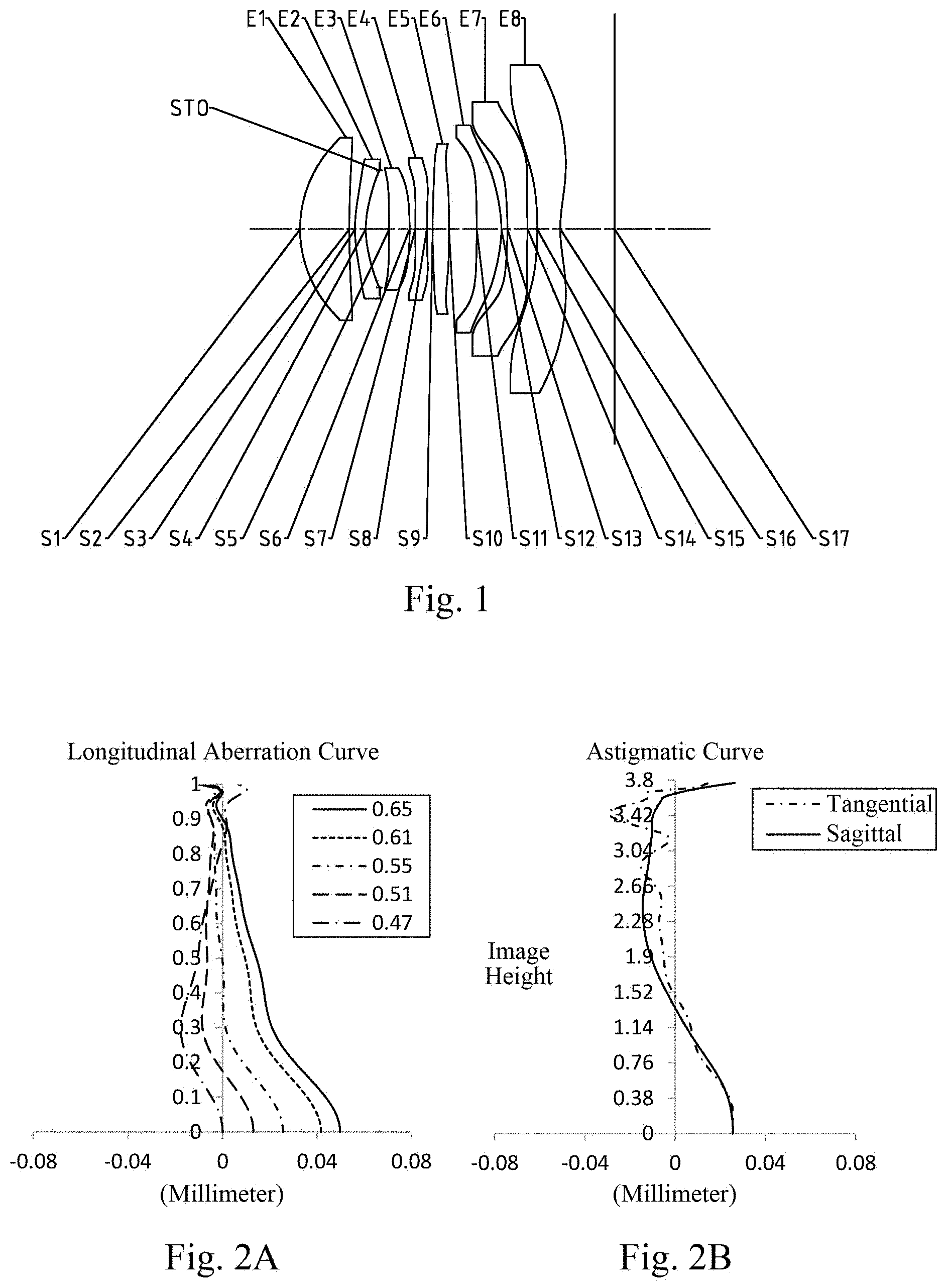
[0024] FIG. 1 shows a schematic configuration diagram of a camera lens assembly according to embodiment 1 of the present application;
[0025] FIG. 2A to 2D show a longitudinal aberration curve, an astigmatism curve, a distortion curve, and a lateral color curve, respectively, of the camera lens assembly of embodiment 1;
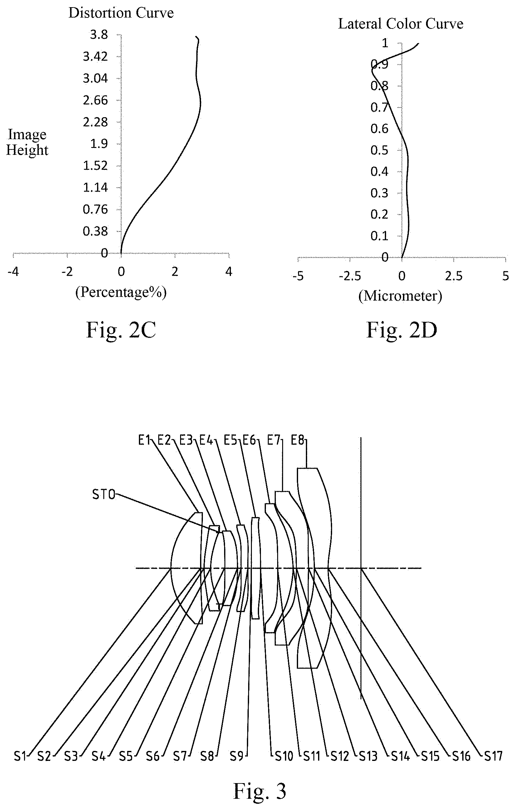
[0026] FIG. 3 shows a schematic configuration diagram of a camera lens assembly according to embodiment 2 of the present application;
[0027] FIG. 4A to 4D show a longitudinal aberration curve, an astigmatism curve, a distortion curve, and a lateral color curve, respectively, of the camera lens assembly of embodiment 2;
[0028] FIG. 5 shows a schematic configuration diagram of a camera lens assembly according to embodiment 3 of the present application;
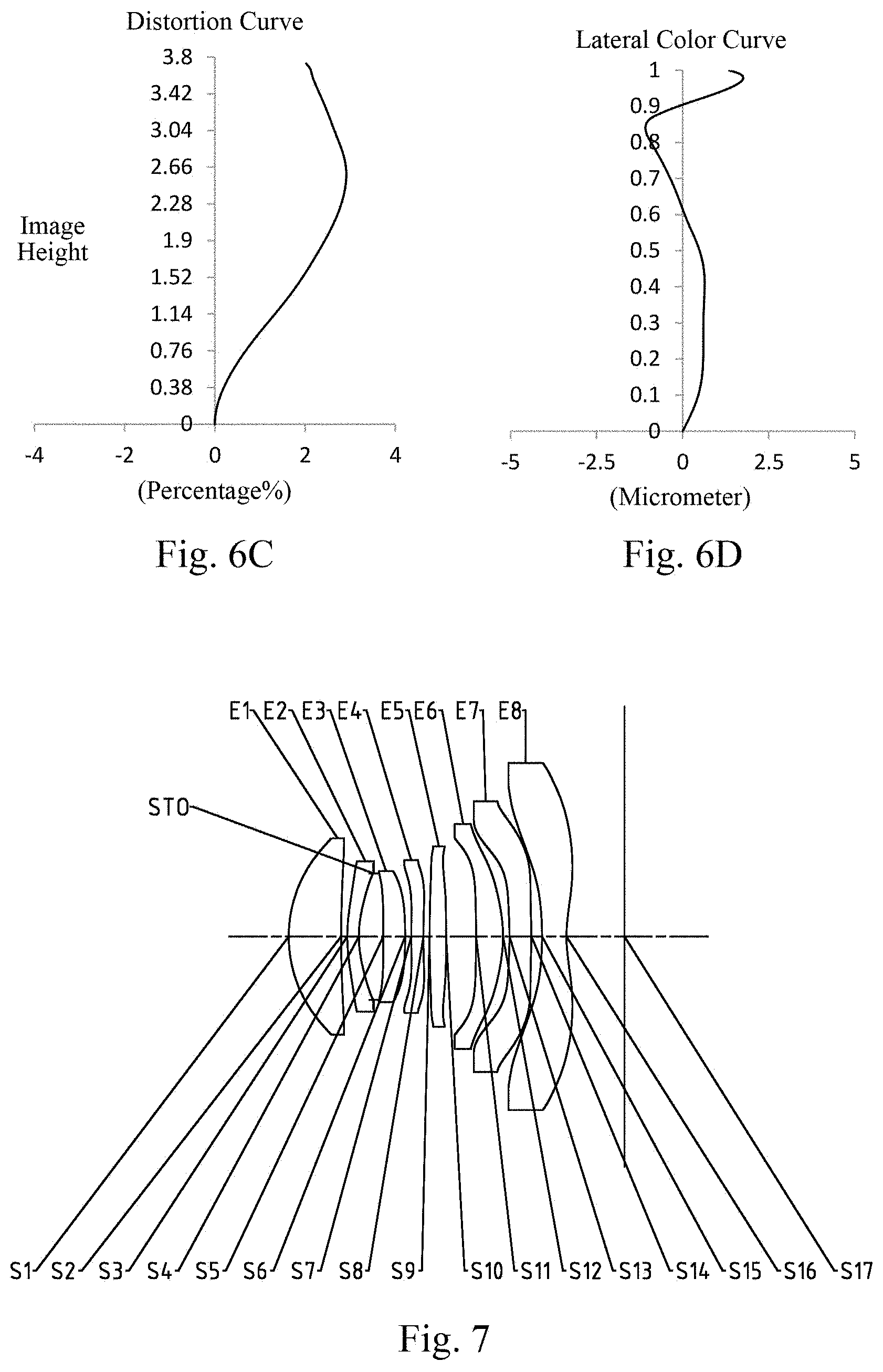
[0029] FIG. 6A to 6D show a longitudinal aberration curve, an astigmatism curve, a distortion curve, and a lateral color curve, respectively, of the camera lens assembly of embodiment 3;
[0030] FIG. 7 shows a schematic configuration diagram of a camera lens assembly according to embodiment 4 of the present application;
[0031] FIG. 8A to 8D show a longitudinal aberration curve, an astigmatism curve, a distortion curve, and a lateral color curve, respectively, of the camera lens assembly of embodiment 4;
[0032] FIG. 9 shows a schematic configuration diagram of a camera lens assembly according to embodiment 5 of the present application;
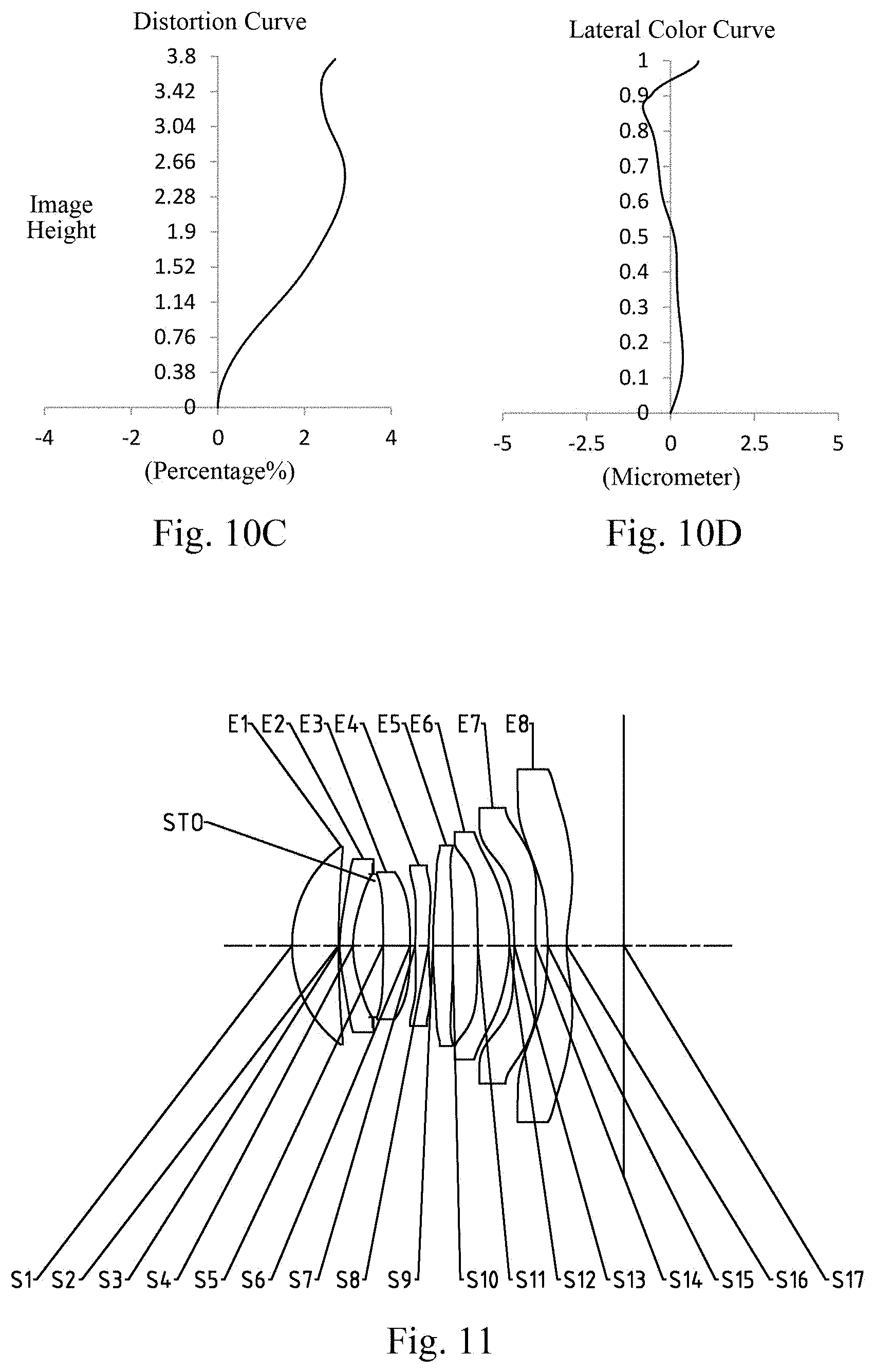
[0033] FIG. 10A to 10D show a longitudinal aberration curve, an astigmatism curve, a distortion curve, and a lateral color curve, respectively, of the camera lens assembly of embodiment 5;
[0034] FIG. 11 shows a schematic configuration diagram of a camera lens assembly according to embodiment 6 of the present application;
[0035] FIG. 12A to 12D show a longitudinal aberration curve, an astigmatism curve, a distortion curve, and a lateral color curve, respectively, of the camera lens assembly of embodiment 6;
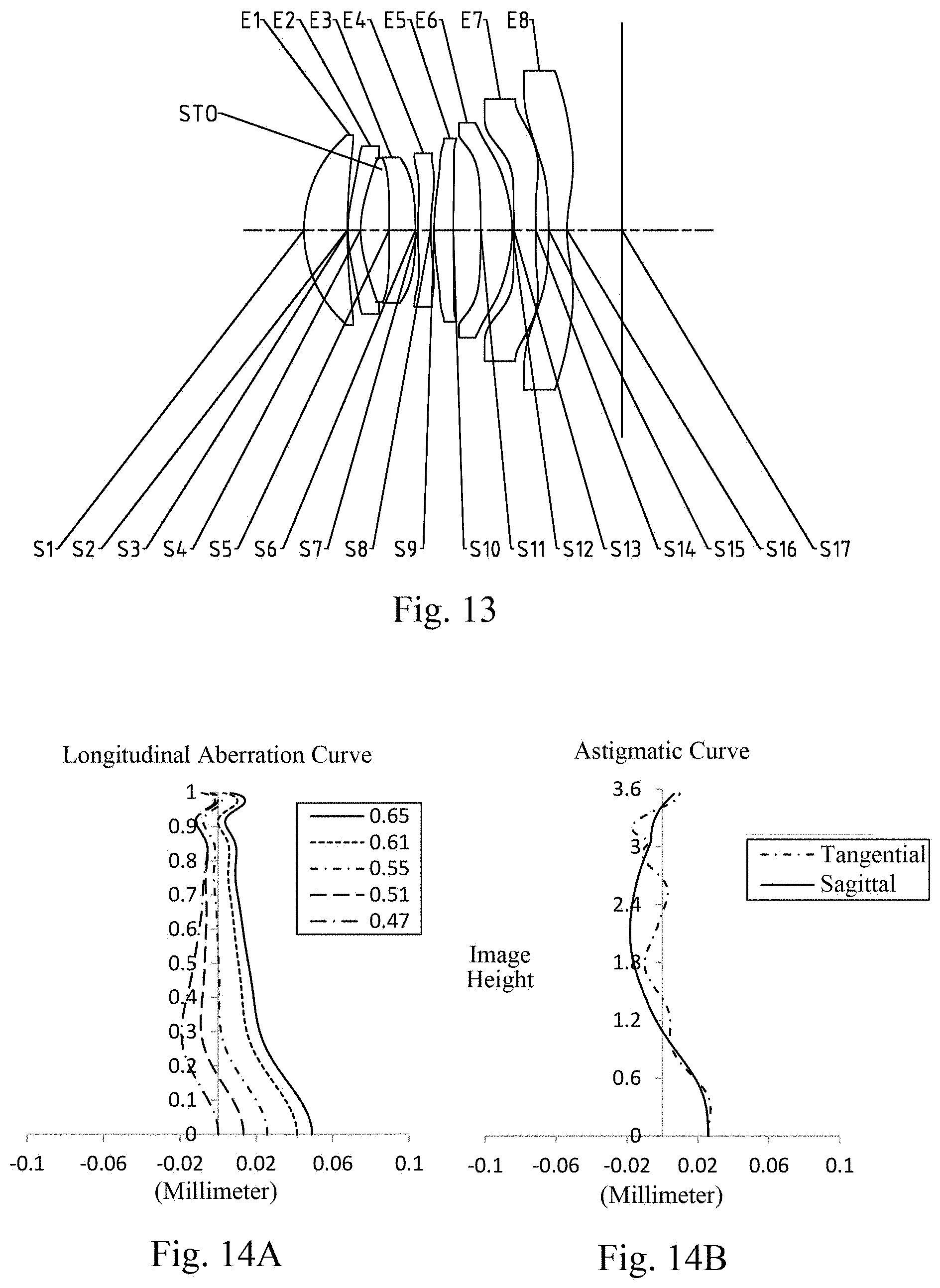
[0036] FIG. 13 shows a schematic configuration diagram of a camera lens assembly according to embodiment 7 of the present application;
[0037] FIG. 14A to 14D show a longitudinal aberration curve, an astigmatism curve, a distortion curve, and a lateral color curve, respectively, of the camera lens assembly of embodiment 7;
[0038] FIG. 15 shows a schematic configuration diagram of a camera lens assembly according to embodiment 8 of the present application;
[0039] FIG. 16A to 16D show a longitudinal aberration curve, an astigmatism curve, a distortion curve, and a lateral color curve, respectively, of the camera lens assembly of embodiment 8;
[0040] FIG. 17 shows a schematic configuration diagram of a camera lens assembly according to embodiment 9 of the present application;
[0041] FIG. 18A to 18D show a longitudinal aberration curve, an astigmatism curve, a distortion curve, and a lateral color curve, respectively, of the camera lens assembly of embodiment 9;
[0042] FIG. 19 shows a schematic configuration diagram of a camera lens assembly according to embodiment 10 of the present application;
[0043] FIG. 20A to 20D show a longitudinal aberration curve, an astigmatism curve, a distortion curve, and a lateral color curve, respectively, of the camera lens assembly of embodiment 10;
[0044] FIG. 21 shows a schematic configuration diagram of a camera lens assembly according to embodiment 11 of the present application;
[0045] FIG. 22A to 22D show a longitudinal aberration curve, an astigmatism curve, a distortion curve, and a lateral color curve, respectively, of the camera lens assembly of embodiment 11;
[0046] FIG. 23 shows a schematic configuration diagram of a camera lens assembly according to embodiment 12 of the present application;
[0047] FIG. 24A to 24D show a longitudinal aberration curve, an astigmatism curve, a distortion curve, and a lateral color curve, respectively, of the camera lens assembly of embodiment 12.
DETAILED DESCRIPTION
[0048] For a better understanding of the present application, various aspects of the present application will be described in more detail with reference to the accompanying drawings. It should be understood that the detailed description is merely illustrative of exemplary embodiments of the present application and does not limit the scope of the present application in any way. Throughout the specification, the same reference numerals designate the same elements. The expression "and/or" includes any and all combinations of one or more of the associated listed items.
[0049] It should be noted that in the present specification, the expressions such as first, second, third etc. are merely used to distinguish one feature from another without limiting the feature. Thus, a first lens discussed below may also be referred to as a second lens or a third lens without departing from the teachings of the present application.
[0050] In the drawings, the thicknesses, sizes and shapes of the lenses have been slightly exaggerated for convenience of explanation. Specifically, spherical or aspherical shapes shown in the drawings are shown by way of example. That is, spherical or aspheric shapes are not limited to the spherical or aspheric shapes shown in the accompanying drawings. The accompanying drawings are merely examples, and not strictly drawn to scale.
[0051] Herein, a paraxial area refers to an area near the optical axis. If a surface of a lens is a convex surface and the position of the convex is not defined, it indicates that the surface of the lens is convex at least in the paraxial area; and if a surface of a lens is a concave surface and the position of the concave is not defined, it indicates that the surface of the lens is concave at least in the paraxial area. In each lens, the surface closest to the object side is referred to as an object-side surface; and in each lens, the surface closest to the image side is referred to as an image-side surface.
[0052] It should be further understood that the terms "comprising," "including," "having," "containing" and/or "contain," when used in the specification, specify the presence of stated features, elements, and/or components, but do not exclude the presence or addition of one or more other features, elements, components and/or combinations thereof. In addition, expressions, such as "at least one of," when preceding a list of features, modify the entire list of features rather than an individual element in the list. Further, the use of "may," when describing implementations of the present application, refers to "one or more implementations of the present application." Also, the term "exemplary" is intended to refer to an example or illustration.
[0053] Unless otherwise defined, all terms (including technical and scientific terms) used herein have the same meaning as commonly understood by those of ordinary skill in the art to which the present application belongs. It will be further understood that terms, such as those defined in commonly used dictionaries, should be interpreted as having a meaning that is consistent with the meaning in the context of the relevant art and will not be interpreted in an idealized or overly formal sense, unless expressly so defined herein.
[0054] It should also be noted that, the embodiments in the present application and the features in the embodiments may be combined with each other on a non-conflict basis. The present application will be described in detail below with reference to the accompanying drawings and in combination with the embodiments.
[0055] The following provides a detailed description of the features, principles, and other aspects of the present application.
[0056] The camera lens assembly according to the exemplary implementations of the present application includes, for example, eight lenses having refractive power, i.e., a first lens, a second lens, a third lens, a fourth lens, a fifth lens, a sixth lens, a seventh lens, and an eighth lens. The eight lenses are arranged in order from an object side of the lens assembly to an image side of the assembly along an optical axis.
[0057] In an exemplary implementation, the first lens may have a positive refractive power, and the image side surface thereof may be a concave surface; the second lens has a positive refractive power or a negative refractive power; the third lens has a positive refractive power or a negative refractive power; the fourth lens has a positive refractive power or a negative refractive power; the fifth lens has a positive refractive power or a negative refractive power; the sixth lens may have a positive refractive power, and an object side surface thereof may be a concave surface; the seventh lens has a positive refractive power or a negative refractive power; and the eighth lens may have a negative refractive power, and the object side surface thereof is a concave surface.
[0058] In an exemplary implementation, an object side surface of the first lens may be a convex surface.
[0059] In an exemplary implementation, an object side surface of the second lens may be a convex surface and an image side surface thereof may be a concave surface.
[0060] In an exemplary implementation, at least one of an object side surface and an image side surface of the third lens may be a convex surface, for example, the image side surface of the third lens may be a convex surface.
[0061] In an exemplary implementation, an image side surface of the sixth lens may be a convex surface.
[0062] In an exemplary implementation, an object side surface of the seventh lens may be a concave surface, and an image side surface thereof may be a convex surface.
[0063] In an exemplary implementation, the camera lens assembly of the present application may satisfy: f/EPD.ltoreq.2.0, where f is a total effective focal length of the camera lens assembly, and EPD is an entrance pupil diameter of the camera lens assembly. More specifically, f and EPD may further satisfy 1.35.ltoreq.f/EPD.ltoreq.1.98. The light amount of the camera lens assembly is reasonably controlled, and thus the low-order aberration of the imaging system is effectively compensated.
[0064] In an exemplary implementation, the camera lens assembly of the present application may satisfy TTL/ImgH.ltoreq.1.6, where TTL is a total track length of the camera lens assembly (i.e., the distance from the center of the object side surface of the first lens to an imaging surface of the camera lens assembly along the optical axis), and ImgH is half of a diagonal length of an effective pixel area on the imaging plane. More specifically, TTL and ImgH may further satisfy 1.24.ltoreq.TTL/ImgH.ltoreq.1.58. The miniaturization characteristic of the imaging system is ensured by reasonably making the ratio of TTL to ImgH satisfy these criteria.
[0065] In an exemplary implementation, the camera lens assembly of the present application may satisfy 75.degree.<FOV<85.degree., where FOV is a full field of view of the camera lens assembly. More specifically, the FOV may further satisfy 77.5.degree..ltoreq.FOV.ltoreq.82.6.sup.0. By making the full field of view FOV this criteria, the imaging range of the imaging system is effectively controlled.
[0066] In an exemplary implementation, the camera lens assembly of the present application may satisfy -10<f2/f<25, where f2 is an effective focal length of the second lens, and f is a total effective focal length of the camera lens assembly. More specifically, f2 and f may further satisfy -10<f2/f<23, e.g., -9.64.ltoreq.f2/f.ltoreq.22.31. By this, the refractive power range of the second lens is reasonably controlled, and the spherical aberration of the imaging system would be reasonable and thus the low-order aberration of the imaging system would be compensated.
[0067] In an exemplary implementation, the camera lens assembly of the present application may satisfy -45<f4/f<25, where f4 is an effective focal length of the fourth lens, and f is a total effective focal length of the camera lens assembly. More specifically, f4 and f may further satisfy -44<f4/f<23, e.g., -43.38.ltoreq.f4/f.ltoreq.22.03. By this, the refractive power range of the fourth lens is reasonably controlled, and thus the coma of the imaging system is effectively controlled.
[0068] In an exemplary implementation, the camera lens assembly of the present application may satisfy -30<f7/f<50, where f7 is an effective focal length of the seventh lens, and f is a total effective focal length of the camera lens assembly. More specifically, f7 and f may further satisfy -24<f7/f<42, e.g., -23.66.ltoreq.f7/f.ltoreq.41.98. By this, the refractive power range of the seventh lens is reasonably controlled, the field curvature of the imaging system is effectively controlled.
[0069] In an exemplary implementation, the camera lens assembly of the present application may satisfy 4<R11/R12<10, where R11 is a radius of curvature of an object side surface of the sixth lens, and R12 is a radius of curvature of an image side surface of the sixth lens. More specifically, R11 and R12 may further satisfy 4.85.ltoreq.R11/R12.ltoreq.9.94. The bending direction and the bending degree of the sixth lens are reasonably controlled, and thus the field curvature of the imaging system is effectively controlled and the imaging quality of the imaging system is improved.
[0070] In an exemplary implementation, the camera lens assembly of the present application may satisfy 2<CT1/CT2<6, where CT1 is a center thickness of the first lens on the optical axis, and CT2 is a center thickness of the second lens on the optical axis. More specifically, CT1 and CT2 may further satisfy 2.47.ltoreq.CT1/CT2.ltoreq.5.12. The ratio of the center thicknesses of the first lens to the second lens is reasonably controlled, and thus there is a good processability of the imaging system.
[0071] In an exemplary implementation, the camera lens assembly of the present application may satisfy 0.5<(TTL/ImgH)/(f/EPD).ltoreq.1.5, where TTL is a total track length of the camera lens assembly, ImgH is half of a diagonal length of an effective pixel area on the imaging plane, f is a total effective focal length of the camera lens assembly, and EPD is an entrance pupil diameter of the camera lens assembly. More specifically, TTL, ImgH, f, and EPD may further satisfy 0.72.ltoreq.(TTL/ImgH)/(f/EPD).ltoreq.1.15. By making the ratio of TTL and ImgH and the ratio of f and EPD satisfy these criteria, the imaging system is ensured to have the characteristics of ultrathinness and large aperture.
[0072] In an exemplary implementation, the camera lens assembly of the present application may satisfy -65<f7/f8<45, where f7 is an effective focal length of the seventh lens, and f8 is an effective focal length of the eighth lens. More specifically, f7 and f8 may further satisfy -63<f7/f8<43, for example, -60.82.ltoreq.f7/f8.ltoreq.42.78. The ratio of the effective focal lengths of the seventh lens and the eighth lens is reasonably controlled, so that the astigmatism of the system can be effectively controlled within a reasonable range.
[0073] In an exemplary implementation, the camera lens assembly of the present application may satisfy -25<f7/R6<20, where f7 is an effective focal length of the seventh lens, and R6 is a radius of curvature of an image side surface of the third lens. More specifically, f7 and R6 may further satisfy -24<f7/R6<17, for example, -23.90.ltoreq.f7/R6.ltoreq.16.39.
[0074] In an exemplary implementation, the above-mentioned camera lens assembly may further include a stop disposed between the second lens and the third lens to improve the image quality of the lens assembly.
[0075] Alternatively, the above-described camera lens assembly may further include an optical filter for correcting color deviation and/or a protective glass for protecting a photosensitive element located on an imaging plane.
[0076] The camera lens assembly according to the above-described implementations of the present application may employ a plurality of lenses, for example, eight lenses as described above. By reasonably assigning the refractive power, the surface type, the center thickness of each lens, the on-axis interval between adjacent lens and the like, the size of the lens assembly is effectively reduced, the sensitivity of the lens assembly is reduced, and the processability of the lens assembly is improved. Therefore, the camera lens assembly is more advantageous to be produced and processed, which in turn makes it more suitable for portable electronic products. Meanwhile, the camera lens assembly configured as above also has advantages such as ultrathinness, large aperture, high imaging quality, and the like.
[0077] In the implementations of the present application, both surfaces of each lens are aspherical surfaces, wherein the curvature varies continuously from the center of the lens to the periphery of the lens. Unlike a spherical lens having a constant curvature from the center of the lens to the periphery of the lens, an aspherical lens has a better radius of curvature characteristic, and has advantages of improving distortion aberration and improving astigmatism aberration. With the aspheric lens, the aberration generated during imaging is eliminated as much as possible, thereby improving the imaging quality.
[0078] However, it will be understood by those skilled in the art that the number of lenses constituting the camera lens assembly may be varied to achieve the various results and advantages described in this specification without departing from the technical solution claimed by the present disclosure. For example, although the implementation is described by taking eight lenses as an example, the optical imaging system is not limited to the implementation of eight lenses. The camera lens assembly may also include other numbers of lenses, if desired. Specific embodiments of the camera lens assembly applicable to the above-described implementations are further described below with reference to the drawings.
Embodiment 1
[0079] A camera lens assembly according to embodiment 1 of the present application is described below with reference to FIGS. 1 to 2D. FIG. 1 shows a schematic configuration diagram of the camera lens assembly according to embodiment 1 of the present application.
[0080] As shown in FIG. 1, a camera lens assembly according to an exemplary implementation of the present application includes, sequentially from an object side of the lens assembly to an image side of the lens assembly along an optical axis, a first lens E1, a second lens E2, a third lens E3, a fourth lens E4, a fifth lens E5, a sixth lens E6, a seventh lens E7, an eighth lens E8, and an imaging plane S17.
[0081] The first lens E1 has a positive refractive power. An object side surface S1 of the first lens E1 is a convex surface. An image side surface S2 of the first lens E1 is a concave surface. The second lens E2 has a negative refractive power. An object side surface S3 of the second lens E2 is a convex surface. An image side surface S4 of the second lens E2 is a concave surface. The third lens E3 has a positive refractive power. An object side surface S5 of the third lens E3 is a concave surface. An image side surface S6 of the third lens E3 is a convex surface. The fourth lens E4 has a negative refractive power. An object side surface S7 of the fourth lens E4 is a convex surface. An image side surface S8 of the fourth lens E4 is a concave surface. The fifth lens E5 has a positive refractive power. An object side surface S9 of the fifth lens E5 is a convex surface. An image side surface S10 of the fifth lens E5 is a convex surface. The sixth lens E6 has a positive refractive power. An object side surface S11 of the sixth lens E6 is a concave surface. An image side surface S12 of the sixth lens E6 is a convex surface. The seventh lens E7 has a negative refractive power. An object side surface S13 of the seventh lens E7 is a concave surface. An image side surface S14 of the seventh lens E7 is a convex surface. The eighth lens E8 has a negative refractive power. An object side surface S15 of the eighth lens E8 is a concave surface. An image side surface S16 of the eighth lens E8 is a concave surface. Light from an object sequentially passes through the respective surfaces S1 to S16 and is finally imaged on the imaging plane S17.
[0082] Alternatively, the camera lens assembly in the present embodiment further includes a stop STO disposed between the second lens E2 and the third lens E3.
[0083] Table 1 shows the surface type, radius of curvature, thickness, material, and conic coefficient of each lens of the camera lens assembly of embodiment 1, wherein the unit of the radius of curvature and the thickness are both millimeters (mm).
TABLE-US-00001 TABLE 1 Material Radius Refrac- Conic Surface Surface of Thick- tive Abbe co- number type curvature ness index number efficient OBJ Spherical Infinite Infinite S1 Aspherical 2.1585 0.8600 1.55 64.1 0.0402 S2 Aspherical 14.0988 0.1000 -99.0000 S3 Aspherical 2.4680 0.1900 1.67 20.4 -3.3532 S4 Aspherical 1.7840 0.2420 -1.7146 STO Spherical Infinite 0.1654 S5 Aspherical -41.2671 0.3589 1.55 64.1 99.0000 S6 Aspherical -5.9700 0.1000 24.4439 S7 Aspherical 156.0558 0.2030 1.67 20.4 -99.0000 S8 Aspherical 33.1772 0.1000 -99.0000 S9 Aspherical 48.4680 0.2845 1.55 64.1 -99.0000 S10 Aspherical -40.7456 0.4857 -99.0000 S11 Aspherical -16.1044 0.4315 1.67 20.4 95.3852 S12 Aspherical -2.0782 0.1069 -8.9058 S13 Aspherical -4.7312 0.3500 1.55 64.1 2.3230 S14 Aspherical -5.9428 0.1720 2.9987 S15 Aspherical -5.8076 0.4000 1.67 20.4 1.7575 S16 Aspherical 2.3104 0.9500 -14.8890 S17 Spherical Infinite
[0084] As can be seen from Table 1, the object side surface and the image side surface of any one of the first lens E1 to the eighth lens E8 are aspheric. In this embodiment, the surface shape of each aspheric lens may be defined by using, but not limited to, the following aspheric formula:
x = ch 2 1 + 1 - ( k + 1 ) c 2 h 2 + A i h i ( 1 ) ##EQU00001##
[0085] where, x is the sag--the axis-component of the displacement of the aspheric surface from the aspheric vertex, when the surface is at height h from the optical axis; c is a paraxial curvature of the aspheric surface, c=1/R (that is, the paraxial curvature c is reciprocal of the radius of curvature R in the above Table 1); k is a conic coefficient (given in the above Table 1); Ai is a correction coefficient for the i-th order of the aspheric surface. Table 2 below shows high-order coefficients A4, A6, A8, A10, A12, A16, A18 and A20, which are applicable to each aspheric surface S1 -S16 in embodiment 1.
TABLE-US-00002 TABLE 2 Surface number A4 A6 A8 A10 A12 S1 8.5886E-04 -2.1473E-03 1.8965E-03 1.0452E-03 -3.6155E-03 S2 -2.7810E-02 6.2108E-02 -8.0208E-02 7.0162E-02 -4.1483E-02 S3 -1.0570E-01 3.4738E-02 1.5408E-01 -5.0365E-01 8.0426E-01 S4 -8.0862E-02 -3.8579E-02 5.3233E-01 -2.0010E+00 4.5366E+00 S5 -1.0700E-03 -2.6583E-01 1.2946E+00 -4.2862E+00 8.9748E+00 S6 6.2762E-02 -7.0295E-01 2.2976E+00 -5.0095E+00 7.4323E+00 S7 1.9345E-01 -1.3529E+00 3.7316E+00 -6.8347E+00 8.3223E+00 S8 3.0481E-01 -1.4390E+00 3.4010E+00 -5.3002E+00 5.4408E+00 S9 2.1927E-01 -8.7917E-01 1.8829E+00 -2.4579E+00 2.0451E+00 S10 2.6143E-03 -1.6573E-01 2.5351E-01 -1.5797E-01 3.3891E-02 S11 4.8603E-02 -1.0400E-01 8.2001E-02 -2.6670E-02 -3.9947E-02 S12 7.3830E-02 -2.1772E-01 3.1788E-01 -3.0583E-01 1.8183E-01 S13 2.2371E-01 -4.7305E-01 5.2207E-01 -4.1151E-01 2.1024E-01 S14 2.7156E-01 -3.5241E-01 2.5669E-01 -1.3345E-01 4.9502E-02 S15 1.1571E-02 -7.9185E-02 7.7459E-02 -3.6334E-02 9.9240E-03 S16 -7.3146E-02 2.1674E-02 -3.6900E-03 8.7609E-04 -3.4110E-04 Surface number A14 A16 A18 A20 S1 3.3201E-03 -1.5200E-03 3.4732E-04 -3.2747E-05 S2 1.5522E-02 -3.3211E-03 3.2489E-04 -5.6616E-06 S3 -7.5885E-01 4.2875E-01 -1.3341E-01 1.7497E-02 S4 -6.4322E+00 5.5937E+00 -2.7232E+00 5.7107E-01 S5 -1.1970E+01 9.8617E+00 -4.5690E+00 9.1139E-01 S6 -7.3943E+00 4.7367E+00 -1.7685E+00 2.9293E-01 S7 -6.5672E+00 3.1981E+00 -8.6153E-01 9.6898E-02 S8 -3.6611E+00 1.5619E+00 -3.8453E-01 4.2181E-02 S9 -1.0965E+00 3.6886E-01 -7.0942E-02 5.9445E-03 S10 1.2797E-02 -9.5076E-03 2.1968E-03 -1.9202E-04 S11 5.6194E-02 -3.0262E-02 7.7042E-03 -7.6013E-04 S12 -6.5203E-02 1.3743E-02 -1.5668E-03 7.4415E-05 S13 -6.5364E-02 1.1890E-02 -1.1580E-03 4.6189E-05 S14 -1.2429E-02 1.9704E-03 -1.7618E-04 6.7386E-06 S15 -1.6523E-03 1.6508E-04 -9.0767E-06 2.1014E-07 S16 8.2677E-05 -1.0693E-05 7.0730E-07 -1.9052E-08
[0086] Table 3 shows effective focal lengths f1 to f8 of the respective lenses, a total effective focal length f of the camera lens assembly, the total track length TTL of the camera lens assembly (i.e., a distance along the optical axis from the center of the object side surface S1 of the first lens E1 to the imaging plane S17), ImgH which is half of a diagonal length of an effective pixel area on the imaging plane S17, and a maximum field of view FOV of the camera lens assembly in embodiment 1.
TABLE-US-00003 TABLE 3 f1 (mm) 4.50 f7 (mm) -46.83 f2 (mm) -10.53 f8 (mm) -2.35 f3 (mm) 12.59 f (mm) 4.53 f4 (mm) -61.19 TTL (mm) 5.50 f5 (mm) 40.12 ImgH (mm) 3.77 f6 (mm) 3.42 FOV (.degree.) 78.6
[0087] The camera lens assembly in embodiment 1 satisfies:
[0088] f/EPD=1.71, where f is the total effective focal length of the camera lens assembly, and EPD is an entrance pupil diameter of the camera lens assembly;
[0089] TTL/ImgH=1.46, where TTL is the total track length of the camera lens assembly, and ImgH is half of the diagonal length of the effective pixel area on the imaging plane S17;
[0090] f2/f=-2.32, where f2 is the effective focal length of the second lens E2, and f is the total effective focal length of the camera lens assembly;
[0091] f4/f=-13.50, where f4 is the effective focal length of the fourth lens E4, and f is the total effective focal length of the camera lens assembly;
[0092] f7/f=-10.33, where f7 is the effective focal length of the seventh lens E7, and f is the total effective focal length of the camera lens assembly;
[0093] R11/R12=7.75, where R11 is a radius of curvature of the object side surface S11 of the sixth lens E6, and R12 is a radius of curvature of the image side surface S12 of the sixth lens E6;
[0094] CT1/CT2=4.53, where CT1 is the center thickness of the first lens E1 on the optical axis, and CT2 is the center thickness of the second lens E2 on the optical axis;
[0095] (TTL/ImgH)/(f/EPD)=0.85, where TTL is the total track length of the camera lens assembly, ImgH is half of the diagonal length of the effective pixel area on the imaging plane S17, f is the total effective focal length of the camera lens assembly, and EPD is the entrance pupil diameter of the camera lens assembly;
[0096] f7/f8=19.92, where f7 is the effective focal length of the seventh lens E7, and f8 is the effective focal length of the eighth lens E8; and
[0097] f7/R6=6.81, where f7 is the effective focal length of the seventh lens E7, and R6 is a radius of curvature of the image side surface S6 of the third lens E3.
[0098] FIG. 2A shows a longitudinal aberration curve of the camera lens assembly of embodiment 1, which represents deviations of focal points converged by light of different wavelengths after passing through the camera lens assembly. FIG. 2B shows an astigmatism curve of the camera lens assembly of embodiment 1, which represents a curvature of a tangential plane and a curvature of a sagittal plane. FIG. 2C shows a distortion curve of the camera lens assembly of embodiment 1, which represents amounts of distortion at different FOVs. FIG. 2D shows a lateral color curve of the camera lens assembly of embodiment 1, which represents deviations of different image heights on the imaging plane after light passes through the lens assembly. As can be seen from FIGS. 2A to 2D, the camera lens assembly according to embodiment 1 can achieve good image quality.
Embodiment 2
[0099] A camera lens assembly according to embodiment 2 of the present application is described below with reference to FIGS. 3 to 4D. In this embodiment and the following embodiments, a description of parts similar to those of embodiment 1 will be omitted for the sake of brevity. FIG. 3 shows a schematic configuration diagram of the camera lens assembly according to embodiment 2 of the present application.
[0100] As shown in FIG. 3, a camera lens assembly according to an exemplary implementation of the present application includes, sequentially from an object side of the lens assembly to an image side of the lens assembly along an optical axis, a first lens E1, a second lens E2, a third lens E3, a fourth lens E4, a fifth lens E5, a sixth lens E6, a seventh lens E7, an eighth lens E8, and an imaging plane S17.
[0101] The first lens E1 has a positive refractive power. An object side surface S1 of the first lens E1 is a convex surface. An image side surface S2 of the first lens E1 is a concave surface. The second lens E2 has a negative refractive power. An object side surface S3 of the second lens E2 is a convex surface. An image side surface S4 of the second lens E2 is a concave surface. The third lens E3 has a positive refractive power. An object side surface S5 of the third lens E3 is a concave surface. An image side surface S6 of the third lens E3 is a convex surface. The fourth lens E4 has a positive refractive power. An object side surface S7 of the fourth lens E4 is a convex surface. An image side surface S8 of the fourth lens E4 is a convex surface. The fifth lens E5 has a positive refractive power. An object side surface S9 of the fifth lens E5 is a concave surface. An image side surface S10 of the fifth lens E5 is a convex surface. The sixth lens E6 has a positive refractive power. An object side surface S11 of the sixth lens E6 is a concave surface. An image side surface S12 of the sixth lens E6 is a convex surface. The seventh lens E7 has a negative refractive power. An object side surface S13 of the seventh lens E7 is a concave surface. An image side surface S14 of the seventh lens E7 is a convex surface. The eighth lens E8 has a negative refractive power. An object side surface S15 of the eighth lens E8 is a concave surface. An image side surface S16 of the eighth lens E8 is a concave surface. Light from an object sequentially passes through the respective surfaces S1 to S16 and is finally imaged on the imaging plane S17.
[0102] Alternatively, the camera lens assembly in the present embodiment further includes a stop STO disposed between the second lens E2 and the third lens E3.
[0103] Table 4 shows the surface type, radius of curvature, thickness, material, and conic coefficient of each lens of the camera lens assembly of embodiment 2, wherein the unit of the radius of curvature and the thickness are both millimeters (mm). Table 5 shows high-order coefficients that may be used for each aspherical surface in embodiment 2, wherein each aspherical surface type can be defined by formula (1) given in embodiment 1 above. Table 6 shows effective focal lengths f1 to f8 of the respective lenses, a total effective focal length f of the camera lens assembly, a total track length TTL of the camera lens assembly, ImgH which is half of a diagonal length of an effective pixel area on the imaging plane S17, and a maximum field of view FOV of the camera lens assembly in embodiment 2.
TABLE-US-00004 TABLE 4 Material Radius Refrac- Conic Surface Surface of Thick- tive Abbe co- number type curvature ness index number efficient OBJ Spherical Infinite Infinite S1 Aspherical 2.1586 0.8600 1.55 64.1 0.0385 S2 Aspherical 14.5930 0.1000 -94.2624 S3 Aspherical 2.5439 0.1904 1.67 20.4 -3.3992 S4 Aspherical 1.8107 0.2412 -1.7094 STO Spherical Infinite 0.1705 S5 Aspherical -43.1767 0.3651 1.55 64.1 5.9445 S6 Aspherical -5.9661 0.1020 24.4211 S7 Aspherical 175.0677 0.1978 1.67 20.4 -99.0081 S8 Aspherical -113.7987 0.1009 -99.0267 S9 Aspherical -34.2864 0.2659 1.55 64.1 51.7806 S10 Aspherical -27.3634 0.4977 -47.3207 S11 Aspherical -16.0453 0.4418 1.67 20.4 95.4126 S12 Aspherical -2.0888 0.0977 -9.1340 S13 Aspherical -4.7409 0.3501 1.55 64.1 2.2799 S14 Aspherical -5.6889 0.1667 3.1865 S15 Aspherical -5.6307 0.4000 1.67 20.4 1.7031 S16 Aspherical 2.2619 0.9500 -15.2351 S17 Spherical Infinite
TABLE-US-00005 TABLE 5 Surface number A4 A6 A8 A10 A12 S1 1.2955E-03 -4.0303E-03 5.0713E-03 -1.5162E-03 -2.9843E-03 S2 -2.7204E-02 5.9210E-02 -7.3851E-02 6.1954E-02 -3.4337E-02 S3 -1.0630E-01 3.3132E-02 1.4412E-01 -4.4025E-01 6.6736E-01 S4 -7.7572E-02 -6.1847E-02 5.9983E-01 -2.0940E+00 4.5736E+00 S5 7.5542E-03 -3.1809E-01 1.4814E+00 -4.6569E+00 9.3142E+00 S6 6.3017E-02 -7.2623E-01 2.4088E+00 -5.3047E+00 7.9219E+00 S7 1.9192E-01 -1.3488E+00 3.7286E+00 -6.8547E+00 8.3850E+00 S8 3.0504E-01 -1.4336E+00 3.3847E+00 -5.2849E+00 5.4494E+00 S9 2.2399E-01 -9.0582E-01 1.9519E+00 -2.5588E+00 2.1371E+00 S10 1.4899E-03 -1.6062E-01 2.3594E-01 -1.1465E-01 -2.9012E-02 S11 4.4031E-02 -9.1718E-02 6.1222E-02 -3.2334E-03 -5.6587E-02 S12 7.4221E-02 -2.1427E-01 3.0770E-01 -2.9345E-01 1.7322E-01 S13 2.2395E-01 -4.7080E-01 5.1804E-01 -4.1026E-01 2.1193E-01 S14 2.7276E-01 -3.5611E-01 2.6034E-01 -1.3585E-01 5.0567E-02 S15 1.1468E-02 -8.1706E-02 8.1395E-02 -3.9003E-02 1.0916E-02 S16 -7.2480E-02 2.1938E-02 -3.6893E-03 8.0384E-04 -3.1144E-04 Surface number A14 A16 A18 A20 S1 3.7938E-03 -1.9269E-03 4.6549E-04 -4.5487E-05 S2 1.1336E-02 -1.7820E-03 8.2376E-06 2.1874E-05 S3 -6.0158E-01 3.2552E-01 -9.6928E-02 1.2119E-02 S4 -6.3531E+00 5.4566E+00 -2.6343E+00 5.4903E-01 S5 -1.1927E+01 9.4805E+00 -4.2580E+00 8.2727E-01 S6 -7.9111E+00 5.0735E+00 -1.8914E+00 3.1205E-01 S7 -6.6532E+00 3.2628E+00 -8.8779E-01 1.0139E-01 S8 -3.6912E+00 1.5876E+00 -3.9432E-01 4.3658E-02 S9 -1.1513E+00 3.9048E-01 -7.6193E-02 6.5418E-03 S10 6.5053E-02 -3.4189E-02 8.3831E-03 -8.3023E-04 S11 6.3047E-02 -3.1607E-02 7.7277E-03 -7.3889E-04 S12 -6.1514E-02 1.2776E-02 -1.4242E-03 6.5330E-05 S13 -6.6990E-02 1.2480E-02 -1.2583E-03 5.2890E-05 S14 -1.2743E-02 2.0289E-03 -1.8238E-04 7.0252E-06 S15 -1.8670E-03 1.9206E-04 -1.0895E-05 2.6081E-07 S16 7.7140E-05 -1.0152E-05 6.8082E-07 -1.8538E-08
TABLE-US-00006 TABLE 6 f1(mm) 4.48 f7(mm) -59.30 f2(mm) -10.20 f8(mm) -2.29 f3(mm) 12.49 f (mm) 4.54 f4(mm) 100.11 TTL (mm) 5.50 f5(mm) 242.05 ImgH (mm) 3.77 f6(mm) 3.44 FOV (.degree.) 78.4
[0104] FIG. 4A shows a longitudinal aberration curve of the camera lens assembly of embodiment 2, which represents deviations of focal points converged by light of different wavelengths after passing through the camera lens assembly. FIG. 4B shows an astigmatism curve of the camera lens assembly of embodiment 2, which represents a curvature of a tangential plane and a curvature of a sagittal plane. FIG. 4C shows a distortion curve of the camera lens assembly of embodiment 2, which represents amounts of distortion at different FOVs. FIG. 4D shows a lateral color curve of the camera lens assembly of embodiment 2, which represents deviations of different image heights on the imaging plane after light passes through the lens assembly. As can be seen from FIGS. 4A to 4D, the camera lens assembly according to embodiment 2 can achieve good image quality.
Embodiment 3
[0105] A camera lens assembly according to embodiment 3 of the present application is described below with reference to FIGS. 5 to 6D. FIG. 5 shows a schematic configuration diagram of the camera lens assembly according to embodiment 3 of the present application.
[0106] As shown in FIG. 5, a camera lens assembly according to an exemplary implementation of the present application includes, sequentially from an object side of the lens assembly to an image side of the lens assembly along an optical axis, a first lens E1, a second lens E2, a third lens E3, a fourth lens E4, a fifth lens E5, a sixth lens E6, a seventh lens E7, an eighth lens E8, and an imaging plane S17.
[0107] The first lens E1 has a positive refractive power. An object side surface S1 of the first lens E1 is a convex surface. An image side surface S2 of the first lens E1 is a concave surface. The second lens E2 has a negative refractive power. An object side surface S3 of the second lens E2 is a convex surface. An image side surface S4 of the second lens E2 is a concave surface. The third lens E3 has a positive refractive power. An object side surface S5 of the third lens E3 is a concave surface. An image side surface S6 of the third lens E3 is a convex surface. The fourth lens E4 has a positive refractive power. An object side surface S7 of the fourth lens E4 is a concave surface. An image side surface S8 of the fourth lens E4 is a convex surface. The fifth lens E5 has a negative refractive power. An object side surface S9 of the fifth lens E5 is a concave surface. An image side surface S10 of the fifth lens E5 is a convex surface. The sixth lens E6 has a positive refractive power. An object side surface S11 of the sixth lens E6 is a concave surface. An image side surface S12 of the sixth lens E6 is a convex surface. The seventh lens E7 has a negative refractive power. An object side surface S13 of the seventh lens E7 is a concave surface. An image side surface S14 of the seventh lens E7 is a convex surface. The eighth lens E8 has a negative refractive power. An object side surface S15 of the eighth lens E8 is a concave surface. An image side surface S16 of the eighth lens E8 is a concave surface. Light from an object sequentially passes through the respective surfaces S1 to S16 and is finally imaged on the imaging plane S17.
[0108] Alternatively, the camera lens assembly in the present embodiment further includes a stop STO disposed between the second lens E2 and the third lens E3.
[0109] Table 7 shows the surface type, radius of curvature, thickness, material, and conic coefficient of each lens of the camera lens assembly of embodiment 3, wherein the unit of the radius of curvature and the thickness are both millimeters (mm). Table 8 shows high-order coefficients that may be used for each aspherical surface in embodiment 3, wherein each aspherical surface type can be defined by formula (1) given in embodiment 1 above. Table 9 shows effective focal lengths f1 to f8 of the respective lenses, a total effective focal length f of the camera lens assembly, a total track length TTL of the camera lens assembly, ImgH which is half of a diagonal length of an effective pixel area on the imaging plane S17, and a maximum field of view FOV of the camera lens assembly in embodiment 3.
TABLE-US-00007 TABLE 7 Material Radius Refrac- Conic Surface Surface of Thick- tive Abbe co- number type curvature ness index number efficient OBJ Spherical Infinite Infinite S1 Aspherical 2.1547 0.8600 1.55 64.1 0.0357 S2 Aspherical 15.2165 0.1000 -91.4745 S3 Aspherical 2.6218 0.1928 1.67 20.4 -3.5211 S4 Aspherical 1.8254 0.2394 -1.7432 STO Spherical Infinite 0.1675 S5 Aspherical -52.2716 0.3705 1.55 64.1 -67.5156 S6 Aspherical -5.9325 0.1008 24.2953 S7 Aspherical -1675.4103 0.2033 1.67 20.4 99.0000 S8 Aspherical -25.6096 0.1031 -99.0000 S9 Aspherical -13.2488 0.2595 1.55 64.1 -47.0977 S10 Aspherical -17.5501 0.4983 -41.8007 S11 Aspherical -16.1541 0.4427 1.67 20.4 95.7890 S12 Aspherical -2.1095 0.0953 -9.4334 S13 Aspherical -4.8375 0.3500 1.55 64.1 2.2305 S14 Aspherical -5.4532 0.1667 3.4429 S15 Aspherical -5.3784 0.4000 1.67 20.4 1.5041 S16 Aspherical 2.2762 0.9500 -14.1874 S17 Spherical Infinite
TABLE-US-00008 TABLE 8 Surface number A4 A6 A8 A10 A12 S1 1.6557E-03 -5.0172E-03 7.7069E-03 -5.1626E-03 -1.8146E-04 S2 -2.5242E-02 5.6396E-02 -7.3193E-02 6.4458E-02 -3.7338E-02 S3 -1.0742E-01 3.5370E-02 1.3863E-01 -4.4694E-01 7.0819E-01 S4 -7.7686E-02 -7.6912E-02 7.1313E-01 -2.5054E+00 5.4162E+00 S5 8.8163E-03 -3.1414E-01 1.4553E+00 -4.5711E+00 9.1323E+00 S6 6.1963E-02 -7.3755E-01 2.4491E+00 -5.3960E+00 8.0833E+00 S7 1.9190E-01 -1.3700E+00 3.8043E+00 -6.9978E+00 8.5434E+00 S8 3.0488E-01 -1.4210E+00 3.3404E+00 -5.1854E+00 5.3040E+00 S9 2.2936E-01 -9.3914E-01 2.0523E+00 -2.7350E+00 2.3284E+00 S10 2.5079E-03 -1.7085E-01 2.6937E-01 -1.7098E-01 2.8052E-02 S11 4.1721E-02 -9.0748E-02 6.7547E-02 -1.4451E-02 -4.6970E-02 S12 7.5801E-02 -2.2190E-01 3.2395E-01 -3.1324E-01 1.8791E-01 S13 2.2884E-01 -4.7883E-01 5.3246E-01 -4.2671E-01 2.2333E-01 S14 2.7393E-01 -3.6058E-01 2.6468E-01 -1.3873E-01 5.1810E-02 S15 1.5869E-02 -9.6282E-02 9.6402E-02 -4.7833E-02 1.4079E-02 S16 -7.5506E-02 2.3718E-02 -3.4880E-03 2.8983E-04 -1.0842E-04 Surface number A14 A16 A18 A20 S1 2.5915E-03 -1.6518E-03 4.3550E-04 -4.4491E-05 S2 1.2673E-02 -1.9764E-03 -1.7292E-05 2.9259E-05 S3 -6.6412E-01 3.7174E-01 -1.1396E-01 1.4626E-02 S4 -7.3706E+00 6.1698E+00 -2.8998E+00 5.8882E-01 S5 -1.1678E+01 9.2644E+00 -4.1494E+00 8.0350E-01 S6 -8.1154E+00 5.2365E+00 -1.9630E+00 3.2527E-01 S7 -6.7526E+00 3.2930E+00 -8.8923E-01 1.0050E-01 S8 -3.5561E+00 1.5116E+00 -3.7102E-01 4.0716E-02 S9 -1.2822E+00 4.4561E-01 -8.9292E-02 7.8896E-03 S10 2.8899E-02 -2.0139E-02 5.3378E-03 -5.5073E-04 S11 5.8655E-02 -3.0700E-02 7.7076E-03 -7.5212E-04 S12 -6.8217E-02 1.4614E-02 -1.7016E-03 8.3043E-05 S13 -7.1797E-02 1.3668E-02 -1.4159E-03 6.1500E-05 S14 -1.3085E-02 2.0860E-03 -1.8751E-04 7.2116E-06 S15 -2.5573E-03 2.8149E-04 -1.7221E-05 4.4888E-07 S16 3.8121E-05 -6.0731E-06 4.5941E-07 -1.3684E-08
TABLE-US-00009 TABLE 9 f1(mm) 4.44 f7(mm) -97.22 f2(mm) -9.97 f8(mm) -2.27 f3(mm) 12.08 f (mm) 4.53 f4(mm) 37.74 TTL (mm) 4.64 f5(mm) -100.02 ImgH (mm) 3.73 f6(mm) 3.48 FOV (.degree.) 78.4
[0110] FIG. 6A shows a longitudinal aberration curve of the camera lens assembly of embodiment 3, which represents deviations of focal points converged by light of different wavelengths after passing through the camera lens assembly. FIG. 6B shows an astigmatism curve of the camera lens assembly of embodiment 3, which represents a curvature of a tangential plane and a curvature of a sagittal plane. FIG. 6C shows a distortion curve of the camera lens assembly of embodiment 3, which represents amounts of distortion at different FOVs. FIG. 6D shows a lateral color curve of the camera lens assembly of embodiment 3, which represents deviations of different image heights on the imaging plane after light passes through the lens assembly. As can be seen from FIGS. 6A to 6D, the camera lens assembly according to embodiment 3 can achieve good image quality.
Embodiment 4
[0111] A camera lens assembly according to embodiment 4 of the present application is described below with reference to FIGS. 7 to 8D. FIG. 7 shows a schematic configuration diagram of the camera lens assembly according to embodiment 4 of the present application.
[0112] As shown in FIG. 7, a camera lens assembly according to an exemplary implementation of the present application includes, sequentially from an object side of the lens assembly to an image side of the lens assembly along an optical axis, a first lens E1, a second lens E2, a third lens E3, a fourth lens E4, a fifth lens E5, a sixth lens E6, a seventh lens E7, an eighth lens E8, and an imaging plane S17.
[0113] The first lens E1 has a positive refractive power. An object side surface S1 of the first lens E1 is a convex surface. An image side surface S2 of the first lens E1 is a concave surface. The second lens E2 has a negative refractive power. An object side surface S3 of the second lens E2 is a convex surface. An image side surface S4 of the second lens E2 is a concave surface. The third lens E3 has a positive refractive power. An object side surface S5 of the third lens E3 is a concave surface. An image side surface S6 of the third lens E3 is a convex surface. The fourth lens E4 has a negative refractive power. An object side surface S7 of the fourth lens E4 is a convex surface. An image side surface S8 of the fourth lens E4 is a concave surface. The fifth lens E5 has a positive refractive power. An object side surface S9 of the fifth lens E5 is a convex surface. An image side surface S10 of the fifth lens E5 is a convex surface. The sixth lens E6 has a positive refractive power. An object side surface S11 of the sixth lens E6 is a concave surface. An image side surface S12 of the sixth lens E6 is a convex surface. The seventh lens E7 has a positive refractive power. An object side surface S13 of the seventh lens E7 is a concave surface. An image side surface S14 of the seventh lens E7 is a convex surface. The eighth lens E8 has a negative refractive power. An object side surface S15 of the eighth lens E8 is a concave surface. An image side surface S16 of the eighth lens E8 is a concave surface. Light from an object sequentially passes through the respective surfaces S1 to S16 and is finally imaged on the imaging plane S17.
[0114] Alternatively, the camera lens assembly in the present embodiment further includes a stop STO disposed between the second lens E2 and the third lens E3.
[0115] Table 10 shows the surface type, radius of curvature, thickness, material, and conic coefficient of each lens of the camera lens assembly of embodiment 4, wherein the unit of the radius of curvature and the thickness are both millimeters (mm). Table 11 shows high-order coefficients that may be used for each aspherical surface in embodiment 4, wherein each aspherical surface type can be defined by formula (1) given in embodiment 1 above. Table 12 shows effective focal lengths f1 to f8 of the respective lenses, a total effective focal length f of the camera lens assembly, a total track length TTL of the camera lens assembly, ImgH which is half of a diagonal length of an effective pixel area on the imaging plane S17, and a maximum field of view FOV of the camera lens assembly in embodiment 4.
TABLE-US-00010 TABLE 10 Material Radius Refrac- Conic Surface Surface of Thick- tive Abbe co- number type curvature ness index number efficient OBJ Spherical Infinite Infinite S1 Aspherical 2.1594 0.8586 1.55 64.1 0.0396 S2 Aspherical 15.5396 0.1000 -92.8521 S3 Aspherical 2.5793 0.1900 1.67 20.4 -3.3531 S4 Aspherical 1.8184 0.2378 -1.7246 STO Spherical Infinite 0.1625 S5 Aspherical -42.1998 0.3587 1.55 64.1 99.0000 S6 Aspherical -5.9728 0.1000 24.4276 S7 Aspherical 136.2282 0.1993 1.67 20.4 -99.0000 S8 Aspherical 58.9514 0.1000 -99.0000 S9 Aspherical 114.0021 0.2709 1.55 64.1 -99.0000 S10 Aspherical -44.9205 0.4914 -99.0000 S11 Aspherical -16.1197 0.4408 1.67 20.4 95.4312 S12 Aspherical -2.1767 0.1064 -8.9312 S13 Aspherical -5.1456 0.3591 1.55 64.1 2.6421 S14 Aspherical -4.8241 0.1737 2.3300 S15 Aspherical -5.0319 0.4006 1.67 20.4 1.4607 S16 Aspherical 2.3216 0.9500 -14.2286 S17 Spherical Infinite
TABLE-US-00011 TABLE 11 Surface number A4 A6 A8 A10 A12 S1 9.5371E-04 -3.1817E-03 4.3482E-03 -1.8532E-03 -1.8125E-03 S2 -2.7604E-02 6.4584E-02 -8.9819E-02 8.6017E-02 -5.6051E-02 S3 -1.0698E-01 4.1594E-02 1.2792E-01 -4.4246E-01 7.1504E-01 S4 -8.4503E-02 -1.4209E-02 4.4744E-01 -1.8347E+00 4.3666E+00 55 -8.0220E-03 -1.8936E-01 9.0778E-01 -3.1362E+00 6.8267E+00 S6 6.2941E-02 -7.0197E-01 2.2907E+00 -4.9836E+00 7.3712E+00 S7 1.9265E-01 -1.3516E+00 3.7328E+00 -6.8414E+00 8.3325E+00 S8 3.0478E-01 -1.4387E+00 3.4005E+00 -5.3010E+00 5.4441E+00 S9 2.1887E-01 -8.7984E-01 1.8852E+00 -2.4621E+00 2.0510E+00 S10 2.9566E-03 -1.6388E-01 2.5016E-01 -1.5332E-01 2.7830E-02 S11 4.6423E-02 -9.6819E-02 7.2316E-02 -1.8905E-02 -4.3921E-02 S12 7.6714E-02 -2.2576E-01 3.2799E-01 -3.1634E-01 1.9043E-01 S13 2.1520E-01 -4.5862E-01 5.0773E-01 -4.0313E-01 2.0817E-01 S14 2.8096E-01 -3.6248E-01 2.6604E-01 -1.3968E-01 5.2393E-02 S15 2.1290E-02 -1.0170E-01 9.8207E-02 -4.6731E-02 1.3069E-02 S16 -7.5294E-02 2.3261E-02 -3.9773E-03 6.8605E-04 -2.2951E-04 Surface number A14 A16 A18 A20 S1 2.8103E-03 -1.5189E-03 3.7870E-04 -3.7750E-05 S2 2.3525E-02 -5.9395E-03 7.9656E-04 -4.1791E-05 S3 -6.7504E-01 3.7914E-01 -1.1663E-01 1.5038E-02 S4 -6.3808E+00 5.6559E+00 -2.7865E+00 5.8850E-01 55 -9.4272E+00 8.0091E+00 -3.8101E+00 7.7751E-01 S6 -7.3053E+00 4.6586E+00 -1.7303E+00 2.8488E-01 S7 -6.5767E+00 3.2043E+00 -8.6423E-01 9.7443E-02 S8 -3.6665E+00 1.5665E+00 -3.8664E-01 4.2595E-02 S9 -1.1020E+00 3.7207E-01 -7.1980E-02 6.0863E-03 S10 1.8162E-02 -1.2281E-02 2.9564E-03 -2.7701E-04 S11 5.7477E-02 -3.0445E-02 7.6784E-03 -7.5093E-04 S12 -6.9810E-02 1.5219E-02 -1.8226E-03 9.2852E-05 S13 -6.5743E-02 1.2243E-02 -1.2346E-03 5.1888E-05 S14 -1.3311E-02 2.1366E-03 -1.9366E-04 7.5267E-06 S15 -2.2406E-03 2.3169E-04 -1.3267E-05 3.2257E-07 S16 5.6583E-05 -7.4708E-06 5.0095E-07 -1.3679E-08
TABLE-US-00012 TABLE 12 f1(mm) 4.44 f7(mm) 100.03 f2(mm) -9.96 f8(mm) -2.26 f3(mm) 12.55 f (mm) 4.52 f4(mm) -150.97 TTL (mm) 5.50 f5(mm) 58.38 ImgH (mm) 3.75 f6(mm) 3.61 FOV (.degree.) 78.2
[0116] FIG. 8A shows a longitudinal aberration curve of the camera lens assembly of embodiment 4, which represents deviations of focal points converged by light of different wavelengths after passing through the camera lens assembly. FIG. 8B shows an astigmatism curve of the camera lens assembly of embodiment 4, which represents a curvature of a tangential plane and a curvature of a sagittal plane. FIG. 8C shows a distortion curve of the camera lens assembly of embodiment 1, which represents amounts of distortion at different FOVs. FIG. 8D shows a lateral color curve of the camera lens assembly of embodiment 4, which represents deviations of different image heights on the imaging plane after light passes through the lens assembly. As can be seen from FIGS. 8A to 8D, the camera lens assembly according to embodiment 4 can achieve good image quality.
Embodiment 5
[0117] A camera lens assembly according to embodiment 5 of the present disclosure is described below with reference to FIG. 9 to FIG. 10D. FIG. 9 shows a schematic configuration diagram of the camera lens assembly according to embodiment 5 of the present disclosure.
[0118] As shown in FIG. 9, the camera lens assembly according to an exemplary implementation of the present disclosure includes a first lens E1, a second lens E2, a third lens E3, a fourth lens E4, a fifth lens E5, a sixth lens E6, a seventh lens E7, an eighth lens E8 and an image plane S17, sequentially from an object side of the lens assembly to an image side of the lens assembly along an optical axis.
[0119] The first lens E1 has a positive refractive power. An object-side surface S1 of the first lens E1 is a convex surface, and an image-side surface S2 of the first lens E1 is a concave surface. The second lens E2 has a negative refractive power. An object-side surface S3 of the second lens E2 is a convex surface, and an image-side surface S4 of the second lens E2 is a concave surface. The third lens E3 has a positive refractive power. An object-side surface S5 of the third lens E3 is a concave surface, and an image-side surface S6 of the third lens E3 is a convex surface. The fourth lens E4 has a negative refractive power. An object-side surface S7 of the fourth lens E4 is a convex surface, and an image-side surface S8 of the fourth lens E4 is a concave surface. The fifth lens E5 has a positive refractive power. An object-side surface S9 of the fifth lens E5 is a convex surface, and an image-side surface S10 of the fifth lens E5 is a convex surface. The sixth lens E6 has a positive refractive power. An object-side surface S11 of the sixth lens E6 is a concave surface, and an image-side surface S12 of the sixth lens E6 is a convex surface. The seventh lens E7 has a negative refractive power. An object-side surface S13 of the seventh lens E7 is a concave surface, and an image-side surface S14 of the seventh lens E7 is a convex surface. The eighth lens E8 has a negative refractive power. An object-side surface S15 of the eighth lens E8 is a concave surface, and an image-side surface S16 of the eighth lens E8 is a concave surface. Light from an object sequentially passes through the respective surfaces S1 to S16 and is finally imaged on the imaging plane S17.
[0120] Alternatively, the camera lens assembly in the present embodiment further includes a stop STO disposed between the second lens E2 and the third lens E3.
[0121] Table 13 shows surface type, radius of curvature, thickness, material, and conic coefficient of each lens of the camera lens assembly in embodiment 5, wherein the units for the radius of curvature and the thickness are millimeters (mm). Table 14 shows high-order coefficients that can be used for each aspherical surface in embodiment 5, wherein the surface type of each aspherical surface can be defined by the formula (1) given in embodiment 1 as described above. Table 15 shows effective focal length f1 to f8 of respective lens, a total effective focal length f of the camera lens assembly, a total track length TTL of the camera lens assembly, half of a diagonal length ImgH of an effective pixel area on the imaging plane S17 and a maximal field of view FOV of the camera lens assembly in embodiment 5.
TABLE-US-00013 TABLE 13 Material Radius Refrac- Conic Surface Surface of Thick- tive Abbe co- number type curvature ness index number efficient OBJ Spherical Infinity Infinity S1 Aspherical 2.1744 0.8869 1.55 64.1 0.0528 S2 Aspherical 9.9661 0.1000 -98.9994 S3 Aspherical 2.5834 0.2000 1.67 20.4 -3.4101 S4 Aspherical 1.9696 0.2378 -1.7346 STO Spherical Infinity 0.1661 S5 Aspherical -40.4969 0.3860 1.55 64.1 99.0000 S6 Aspherical -6.0645 0.1000 24.0679 S7 Aspherical 117.3786 0.2008 1.67 20.4 10.7783 S8 Aspherical 62.5638 0.1000 -99.0000 S9 Aspherical 1357.0693 0.2879 1.55 64.1 -99.0000 S10 Aspherical -34.0891 0.4357 99.0000 S11 Aspherical -16.0980 0.4553 1.67 20.4 95.5680 S12 Aspherical -2.0659 0.1039 -9.3865 S13 Aspherical -4.9512 0.3447 1.55 64.1 2.4187 S14 Aspherical -6.2965 0.1739 3.1516 S15 Aspherical -5.8000 0.3710 1.67 20.4 1.7549 S16 Aspherical 2.3090 0.9500 -14.5447 S17 Spherical Infinity
TABLE-US-00014 TABLE 14 Surface number A4 A6 A8 A10 A12 S1 -5.9655E-04 4.3365E-03 -1.7058E-02 3.1307E-02 -3.1808E-02 S2 -3.3357E-02 7.6078E-02 -1.0436E-01 1.0034E-01 -6.6726E-02 S3 -1.0372E-01 3.9535E-02 1.2940E-01 -4.4164E-01 6.9309E-01 S4 -7.2823E-02 -4.6095E-02 5.6512E-01 -2.1784E+00 4.9177E+00 55 -4.5950E-04 -2.7272E-01 1.2739E+00 -3.9833E+00 7.8692E+00 S6 6.2325E-02 -6.8315E-01 2.1912E+00 -4.6816E+00 6.8169E+00 S7 1.9491E-01 -1.3534E+00 3.7322E+00 -6.8567E+00 8.4074E+00 S8 3.0384E-01 -1.4410E+00 3.4041E+00 -5.3026E+00 5.4416E+00 S9 2.1863E-01 -8.7699E-01 1.8773E+00 -2.4501E+00 2.0381E+00 S10 3.2345E-03 -1.6557E-01 2.4793E-01 -1.5147E-01 3.0532E-02 S11 5.3398E-02 -1.2180E-01 1.1339E-01 -6.2046E-02 -1.3682E-02 S12 7.3342E-02 -2.1264E-01 3.1098E-01 -2.9885E-01 1.7771E-01 S13 2.2685E-01 -4.7835E-01 5.3230E-01 -4.2494E-01 2.2036E-01 S14 2.7142E-01 -3.5191E-01 2.5558E-01 -1.3232E-01 4.8872E-02 S15 1.2419E-02 -8.5358E-02 8.5394E-02 -4.1013E-02 1.1450E-02 S16 -7.7602E-02 2.4645E-02 -5.2011E-03 1.5461E-03 -5.5990E-04 Surface number A14 A16 A18 A20 S1 1.9121E-02 -6.7539E-03 1.2934E-03 -1.0491E-04 S2 2.9133E-02 -7.8845E-03 1.1927E-03 -7.7332E-05 S3 -6.2900E-01 3.3752E-01 -9.8903E-02 1.2144E-02 S4 -6.7856E+00 5.6508E+00 -2.6061E+00 5.1321E-01 55 -9.8756E+00 7.6409E+00 -3.3202E+00 6.2018E-01 S6 -6.6394E+00 4.1361E+00 -1.4883E+00 2.3519E-01 S7 -6.7145E+00 3.3313E+00 -9.2329E-01 1.0842E-01 S8 -3.6585E+00 1.5574E+00 -3.8159E-01 4.1463E-02 S9 -1.0924E+00 3.6744E-01 -7.0696E-02 5.9310E-03 S10 1.3589E-02 -9.6206E-03 2.2436E-03 -2.0292E-04 S11 4.3620E-02 -2.6556E-02 7.0942E-03 -7.1664E-04 S12 -6.4147E-02 1.3746E-02 -1.6155E-03 8.0611E-05 S13 -6.9870E-02 1.3072E-02 -1.3275E-03 5.6462E-05 S14 -1.2223E-02 1.9307E-03 -1.7200E-04 6.5524E-06 S15 -1.9471E-03 1.9882E-04 -1.1195E-05 2.6634E-07 S16 1.2846E-04 -1.6407E-05 1.0948E-06 -3.0027E-08
TABLE-US-00015 TABLE 15 f1(mm) 4.84 f7(mm) -46.16 f2(mm) -13.87 f8(mm) -2.35 f3(mm) 12.86 f (mm) 4.49 f4(mm) -194.71 TTL (mm) 5.50 f5(mm) 60.21 ImgH (mm) 3.77 f6(mm) 3.39 FOV (.degree.) 79.3
[0122] FIG. 10A shows a longitudinal aberration curve of the camera lens assembly of embodiment 5, which represents deviations of focal points converged by light of different wavelengths after passing through the lens assembly. FIG. 10B shows an astigmatism curve of the camera lens assembly of embodiment 5, which represents a curvature of a tangential plane and a curvature of a sagittal plane. FIG. 10C shows a distortion curve of the camera lens assembly of embodiment 5, which represents amounts of distortion at different FOVs. FIG. 10D shows a lateral color curve of the camera lens assembly of embodiment 5, which represents deviations of different image heights on the imaging plane after light passes through the lens assembly. As can be seen from FIG. 10A to FIG. 10D, the camera lens assembly according to embodiment 5 can achieve good imaging quality.
Embodiment 6
[0123] A camera lens assembly according to embodiment 6 of the present disclosure is described below with reference to FIG. 11 to FIG. 12D. FIG. 11 shows a schematic configuration diagram of the camera lens assembly according to embodiment 6 of the present disclosure.
[0124] As shown in FIG. 11, a camera lens assembly according to an exemplary implementation of the present disclosure includes a first lens E1, a second lens E2, a third lens E3, a fourth lens E4, a fifth lens E5, a sixth lens E6, a seventh lens E7, an eighth lens E8, and an image plane S17, sequentially from an object side of the lens assembly to an image side of the lens assembly along an optical axis.
[0125] The first lens E1 has a positive refractive power. An object-side surface S1 of the first lens E1 is a convex surface, and an image-side surface S2 of the first lens E1 is a concave surface. The second lens E2 has a negative refractive power. An object-side surface S3 of the second lens E2 is a convex surface, and an image-side surface S4 of the second lens E2 is a concave surface. The third lens E3 has a positive refractive power. An object-side surface S5 of the third lens E3 is a concave surface, and an image-side surface S6 of the third lens E3 is a convex surface. The fourth lens E4 has a negative refractive power. An object-side surface S7 of the fourth lens E4 is a convex surface, and an image-side surface S8 of the fourth lens E4 is a concave surface. The fifth lens E5 has a positive refractive power. An object-side surface S9 of the fifth lens E5 is a convex surface, and an image-side surface S10 of the fifth lens E5 is a concave surface. The sixth lens E6 has a positive refractive power. An object-side surface S11 of the sixth lens E6 is a concave surface, and an image-side surface S12 of the sixth lens E6 is a convex surface. The seventh lens E7 has a negative refractive power. An object-side surface S13 of the seventh lens E7 is a concave surface, and an image-side surface S14 of the seventh lens E7 is a convex surface. The eighth lens E8 has a negative refractive power. An object-side surface S15 of the eighth lens E8 is a concave surface, and an image-side surface S16 of the eighth lens E8 is a concave surface. Light from an object sequentially passes through the respective surfaces S1 to S16 and is finally imaged on the imaging plane S17.
[0126] Alternatively, the camera lens assembly in the present embodiment further includes a stop STO disposed between the second lens E2 and the third lens E3.
[0127] Table 16 shows surface type, radius of curvature, thickness, material, and conic coefficient of each lens of the camera lens assembly of embodiment 6, wherein the units for the radius of curvature and the thickness are millimeters (mm). Table 17 shows high-order coefficients that can be used for each aspherical surface in embodiment 6, wherein the surface type of each aspherical surface can be defined by the formula (1) given in embodiment 1 as described above. Table 18 shows effective focal lengths f1 to f8 of the respective lens, a total effective focal length f of the camera lens assembly, a total track length TTL of the camera lens assembly, half of a diagonal length ImgH of an effective pixel area on the imaging plane S17, and a maximal field of view FOV of the camera lens assembly in embodiment 6.
TABLE-US-00016 TABLE 16 Sur- Material face Refrac- Conic num- Surface Radius of Thick- tive Abbe coeffi- ber type curvature ness index number cient OBJ Spherical Infinity Infinity S1 Aspherical 2.1428 0.7697 1.55 64.1 0.1765 S2 Aspherical 12.4708 0.0214 -87.3760 S3 Aspherical 2.3121 0.2200 1.67 20.4 -4.0039 S4 Aspherical 1.7408 0.3254 -1.9380 STO Spherical Infinity 0.1734 S5 Aspherical -44.5375 0.4486 1.55 64.1 -21.0989 S6 Aspherical -6.4022 0.0856 24.0531 S7 Aspherical 15.9110 0.2200 1.67 20.4 -43.7189 S8 Aspherical 8.6358 0.0723 -49.7621 S9 Aspherical 13.0376 0.3231 1.55 64.1 -99.0000 S10 Aspherical 1232.5044 0.4184 99.0000 S11 Aspherical -16.3314 0.5248 1.67 20.4 95.0894 S12 Aspherical -2.0629 0.0793 -8.0523 S13 Aspherical -5.4752 0.3552 1.55 64.1 2.8756 S14 Aspherical -6.7366 0.1978 4.0351 S15 Aspherical -5.7283 0.3150 1.67 20.4 1.9179 S16 Aspherical 2.3546 0.9500 -9.9941 S17 Spherical Infinity
TABLE-US-00017 TABLE 17 Surface number A4 A6 A8 A10 A12 S1 5.6112E-03 -1.3008E-02 2.9644E-02 -4.2907E-02 4.0138E-02 S2 -3.4317E-02 6.0076E-02 -6.1347E-02 4.3829E-02 -2.1249E-02 S3 -7.7024E-02 -2.5502E-03 5.9280E-02 -7.4341E-02 5.3113E-02 S4 -4.6286E-02 -4.7485E-02 8.9528E-02 -3.3670E-02 -4.1832E-02 S5 5.0341E-03 -1.4585E-01 4.5944E-01 -1.1229E+00 1.7342E+00 S6 1.0440E-01 -6.9503E-01 1.8209E+00 -3.2634E+00 4.0036E+00 S7 1.7688E-01 -1.1283E+00 2.7985E+00 -4.7026E+00 5.3621E+00 S8 2.5704E-01 -1.1799E+00 2.5986E+00 -3.7542E+00 3.5640E+00 S9 2.0152E-01 -7.7886E-01 1.6215E+00 -2.0723E+00 1.6753E+00 S10 -3.3667E-03 -7.4275E-02 4.8624E-02 8.6578E-02 -1.5747E-01 S11 3.1908E-02 -5.5474E-02 1.0034E-02 3.4028E-02 -7.4181E-02 S12 8.3061E-02 -1.9700E-01 2.4585E-01 -2.2919E-01 1.4112E-01 S13 2.3098E-01 -4.0943E-01 3.5040E-01 -2.2239E-01 9.6489E-02 S14 2.8529E-01 -3.5858E-01 2.3330E-01 -1.0031E-01 2.8977E-02 S15 4.6590E-02 -1.5909E-01 1.4665E-01 -7.0220E-02 2.0219E-02 S16 -9.2593E-02 2.6699E-02 -2.5980E-03 -1.6972E-04 3.0637E-06 Surface number A14 A16 A18 A20 S1 -2.3778E-02 8.6250E-03 -1.7366E-03 1.4651E-04 S2 6.6457E-03 -1.2612E-03 1.2924E-04 -5.2791E-06 S3 -1.8517E-02 2.8514E-04 1.7862E-03 -3.8254E-04 S4 5.3441E-02 -6.3115E-03 -1.5425E-02 6.2898E-03 S5 -1.6837E+00 1.0023E+00 -3.3489E-01 4.8124E-02 S6 -3.2627E+00 1.6853E+00 -4.9993E-01 6.5116E-02 S7 -4.0116E+00 1.8724E+00 -4.9059E-01 5.4782E-02 S8 -2.2098E+00 8.6686E-01 -1.9591E-01 1.9647E-02 S9 -8.6558E-01 2.7917E-01 -5.1364E-02 4.1161E-03 S10 1.1137E-01 -4.1504E-02 8.0997E-03 -6.5841E-04 S11 7.0766E-02 -3.4940E-02 8.6471E-03 -8.4180E-04 S12 -5.4168E-02 1.2606E-02 -1.6443E-03 9.2824E-05 S13 -2.5421E-02 3.7500E-03 -2.6949E-04 6.2428E-06 S14 -5.4160E-03 6.0784E-04 -3.5053E-05 6.8299E-07 S15 -3.6235E-03 3.9660E-04 -2.4329E-05 6.4218E-07 S16 1.4330E-05 -2.2404E-06 1.2203E-07 -2.0285E-09
TABLE-US-00018 TABLE 18 f1(mm) 4.56 f7(mm) -58.84 f2(mm) -12.13 f8(mm) -2.38 f3(mm) 13.48 f (mm) 4.46 f4(mm) -27.75 TTL (mm) 5.50 f5(mm) 23.85 ImgH (mm) 3.77 f6(mm) 3.38 FOV (.degree.) 79.5
[0128] FIG. 12A shows a longitudinal aberration curve of the camera lens assembly of embodiment 6, which represents deviations of focal points converged by light of different wavelengths after passing through the lens assembly. FIG. 12B shows an astigmatism curve of the camera lens assembly of embodiment 6, which represents a curvature of a tangential plane and a curvature of a sagittal plane. FIG. 12C shows a distortion curve of the camera lens assembly of embodiment 6, which represents amounts of distortion at different FOVs. FIG. 12D shows a lateral color curve of the camera lens assembly of embodiment 6, which represents deviations of different image heights on the imaging plane after light passes through the lens assembly. As can be seen from FIG. 12A to FIG. 12D, the camera lens assembly according to embodiment 6 can achieve good imaging quality.
Embodiment 7
[0129] A camera lens assembly according to embodiment 7 of the present disclosure is described below with reference to FIG. 13 to FIG. 14D. FIG. 13 shows a schematic configuration diagram of a camera lens assembly according to embodiment 7 of the present disclosure.
[0130] As shown in FIG. 13, the camera lens assembly according to an exemplary implementation of the present disclosure includes a first lens E1, a second lens E2, a third lens E3, a fourth lens E4, a fifth lens E5, a sixth lens E6, a seventh lens E7, an eighth lens E8, and an image plane S17, sequentially from an object side of the lens assembly to an image side of the lens assembly along an optical axis.
[0131] The first lens E1 has a positive refractive power. An object-side surface S1 of the first lens E1 is a convex surface, and an image-side surface S2 of the first lens E1 is a concave surface. The second lens E2 has a negative refractive power. An object-side surface S3 of the second lens E2 is a convex surface, and an image-side surface S4 of the second lens E2 is a concave surface. The third lens E3 has a positive refractive power. An object-side surface S5 of the third lens E3 is a concave surface, and an image-side surface S6 of the third lens E3 is a convex surface. The fourth lens E4 has a negative refractive power. An object-side surface S7 of the fourth lens E4 is a convex surface, and an image-side surface S8 of the fourth lens E4 is a concave surface. The fifth lens E5 has a positive refractive power. An object-side surface S9 of the fifth lens E5 is a convex surface, and an image-side surface S10 of the fifth lens E5 is a concave surface. The sixth lens E6 has a positive refractive power. An object-side surface S11 of the sixth lens E6 is a concave surface, and an image-side surface S12 of the sixth lens E6 is a convex surface. The seventh lens E7 has a negative refractive power. An object-side surface S13 of the seventh lens E7 is a concave surface, and an image-side surface S14 of the seventh lens E7 is a convex surface. The eighth lens E8 has a negative refractive power. An object-side surface S15 of the eighth lens E8 is a concave surface, and an image-side surface S16 of the eighth lens E8 is a concave surface. Light from an object sequentially passes through the respective surfaces S1 to S16 and is finally imaged on the imaging plane S17.
[0132] Alternatively, the camera lens assembly in the present embodiment further includes a stop STO disposed between the second lens E2 and the third lens E3.
[0133] Table 19 shows surface type, radius of curvature, thickness, material, and conic coefficient of each lens of the camera lens assembly in embodiment 7, wherein the units for the radius of curvature and the thickness are millimeters (mm). Table 20 shows high-order coefficients that can be used for each aspherical surface in embodiment 7, wherein the surface type of each aspherical surface can be defined by the formula (1) given in embodiment 1 as described above. Table 21 shows effective focal lengths f1 to f8 of the respective lens, a total effective focal length f of the camera lens assembly, a total optical length TTL of the camera lens assembly, half of a diagonal length ImgH of an effective pixel area on the imaging plane S17, and a maximal field of view FOV of the camera lens assembly in embodiment 7.
TABLE-US-00019 TABLE 19 Sur- Material face Refrac- Conic num- Surface Radius of Thick- tive Abbe coeffi- ber type curvature ness index number cient OBJ Spherical Infinity Infinity S1 Aspherical 2.2658 0.7500 1.55 64.1 0.1390 S2 Aspherical 7.9258 0.0100 -59.0998 S3 Aspherical 2.1850 0.2200 1.67 20.4 -3.9329 S4 Aspherical 1.8520 0.3148 -2.4037 STO Spherical Infinity 0.1783 S5 Aspherical -119.9077 0.4549 1.55 64.1 -99.0000 S6 Aspherical -6.5950 0.0439 23.3824 S7 Aspherical 7.8785 0.2200 1.67 20.4 -65.9538 S8 Aspherical 3.7671 0.0606 -52.4904 S9 Aspherical 4.0770 0.3299 1.55 64.1 -83.1925 S10 Aspherical 12.2630 0.4774 -99.0000 S11 Aspherical -16.2537 0.5431 1.67 20.4 95.7305 S12 Aspherical -2.0313 0.0300 -7.1098 S13 Aspherical -7.6479 0.3772 1.55 64.1 5.7281 S14 Aspherical -11.2530 0.2249 8.7655 S15 Aspherical -7.3504 0.3150 1.67 20.4 3.3943 S16 Aspherical 2.3287 0.9500 -7.6593 S17 Spherical Infinity
TABLE-US-00020 TABLE 20 Surface number A4 A6 A8 A10 A12 S1 6.5400E-03 -1.6727E-02 3.5854E-02 -5.0862E-02 4.6677E-02 S2 -5.0085E-02 1.1672E-01 -1.5133E-01 1.3418E-01 -8.1803E-02 S3 -7.4827E-02 3.7887E-02 -2.6713E-02 4.2004E-02 -7.0994E-02 S4 -2.9573E-02 -7.6737E-02 1.6332E-01 -2.1996E-01 2.3411E-01 S5 -6.1997E-03 -8.4195E-02 2.3586E-01 -5.3356E-01 7.4776E-01 S6 1.5393E-01 -9.8286E-01 2.6308E+00 -4.5434E+00 5.2393E+00 S7 1.7406E-01 -1.1283E+00 2.7362E+00 -4.3218E+00 4.5720E+00 S8 1.7761E-01 -7.6274E-01 1.5010E+00 -1.9243E+00 1.5679E+00 S9 1.4871E-01 -4.9931E-01 9.5909E-01 -1.0998E+00 7.3768E-01 S10 -3.8847E-02 5.3279E-02 -1.6260E-01 3.2378E-01 -3.4528E-01 S11 -1.8797E-03 7.6391E-03 -3.5534E-02 3.3444E-02 -4.0511E-02 S12 6.8107E-02 -1.4657E-01 1.4969E-01 -1.1205E-01 5.0912E-02 S13 2.3114E-01 -3.7251E-01 2.6909E-01 -1.3289E-01 3.9072E-02 S14 2.8890E-01 -3.6405E-01 2.3776E-01 -1.0393E-01 3.0973E-02 S15 6.7164E-02 -1.8462E-01 1.5580E-01 -7.0447E-02 1.9642E-02 S16 -8.7622E-02 1.8052E-02 6.7305E-04 -2.8729E-04 -2.4356E-04 Surface number A14 A16 A18 A20 S1 -2.6974E-02 9.4548E-03 -1.8175E-03 1.4408E-04 S2 3.3385E-02 -8.7439E-03 1.3350E-03 -9.0947E-05 S3 7.0488E-02 -3.8444E-02 1.1008E-02 -1.2983E-03 S4 -2.0396E-01 1.3382E-01 -5.3315E-02 9.3625E-03 S5 -6.4636E-01 3.3665E-01 -9.6735E-02 1.1722E-02 S6 -3.9877E+00 1.9189E+00 -5.2830E-01 6.3405E-02 S7 -3.1924E+00 1.4092E+00 -3.5403E-01 3.8338E-02 S8 -8.0645E-01 2.5835E-01 -4.7891E-02 4.0901E-03 S9 -2.8359E-01 5.7947E-02 -4.7283E-03 -5.5753E-05 S10 2.0805E-01 -7.1905E-02 1.3475E-02 -1.0749E-03 S11 3.7505E-02 -1.9271E-02 4.9620E-03 -4.9691E-04 S12 -1.1427E-02 5.3579E-04 2.2506E-04 -2.9721E-05 S13 -3.8174E-03 -9.2643E-04 2.7027E-04 -1.9553E-05 S14 -6.0953E-03 7.4686E-04 -5.0690E-05 1.4194E-06 S15 -3.4926E-03 3.8743E-04 -2.4490E-05 6.7366E-07 S16 9.7119E-05 -1.5020E-05 1.1188E-06 -3.3553E-08
TABLE-US-00021 TABLE 21 f1(mm) 5.49 f7(mm) -44.89 f2(mm) -24.14 f8(mm) -2.53 f3(mm) 12.62 f (mm) 4.35 f4(mm) -10.71 TTL (mm) 5.50 f5(mm) 10.90 ImgH (mm) 3.55 f6(mm) 3.32 FOV (.degree.) 77.5
[0134] FIG. 14A shows a longitudinal aberration curve of the camera lens assembly of embodiment 7, which represents deviations of focal points converged by light of different wavelengths after passing through the lens assembly. FIG. 14B shows an astigmatism curve of the camera lens assembly of embodiment 7, which represents a curvature of a tangential plane and a curvature of a sagittal plane. FIG. 14C shows a distortion curve of the camera lens assembly of embodiment 7, which represents amounts of distortion at different FOVs. FIG. 14D shows a lateral color curve of the camera lens assembly of embodiment 7, which represents deviations of different image heights on the imaging plane after light passes through the lens assembly. As can be seen from FIG. 14A to FIG. 14D, the camera lens assembly according to embodiment 7 can achieve good imaging quality.
Embodiment 8
[0135] A camera lens assembly according to embodiment 8 of the present disclosure is described below with reference to FIG. 15 to FIG. 16D. FIG. 15 shows a schematic configuration diagram of the camera lens assembly according to embodiment 8 of the present disclosure.
[0136] As shown in FIG. 15, the camera lens assembly according to an exemplary embodiment of the present disclosure includes a first lens E1, a second lens E2, a third lens E3, a fourth lens E4, a fifth lens E5, a sixth lens E6, a seventh lens E7, an eighth lens E8, and an image plane S17, sequentially from an object side of the lens assembly to an image side of the lens assembly along an optical axis.
[0137] The first lens E1 has a positive refractive power. An object-side surface S1 of the first lens E1 is a convex surface, and an image-side surface S2 of the first lens E1 is a concave surface. The second lens E2 has a negative refractive power. An object-side surface S3 of the second lens E2 is a convex surface, and an image-side surface S4 of the second lens E2 is a concave surface. The third lens E3 has a positive refractive power. An object-side surface S5 of the third lens E3 is a convex surface, and an image-side surface S6 of the third lens E3 is a convex surface. The fourth lens E4 has a negative refractive power. An object-side surface S7 of the fourth lens E4 is a convex surface, and an image-side surface S8 of the fourth lens E4 is a concave surface. The fifth lens E5 has a positive refractive power. An object-side surface S9 of the fifth lens E5 is a convex surface, and an image-side surface S10 of the fifth lens E5 is a concave surface. The sixth lens E6 has a positive refractive power. An object-side surface S11 of the sixth lens E6 is a concave surface, and an image-side surface S12 of the sixth lens E6 is a convex surface. The seventh lens E7 has a negative refractive power. An object-side surface S13 of the seventh lens E7 is a concave surface, and an image-side surface S14 of the seventh lens E7 is a convex surface. The eighth lens E8 has a negative refractive power. An object-side surface S15 of the eighth lens E8 is a concave surface, and an image-side surface S16 of the eighth lens E8 is a concave surface. Light from an object sequentially passes through the respective surfaces S1 to S16 and is finally imaged on the imaging plane S17.
[0138] Alternatively, the camera lens assembly in the present embodiment further includes a stop STO disposed between the second lens E2 and the third lens E3.
[0139] Table 22 shows surface type, radius of curvature, thickness, material, and conic coefficient of each lens of the camera lens assembly in embodiment 8, wherein the units for the radius of curvature and the thickness are millimeters (mm). Table 23 shows high-order coefficients that can be used for each aspherical surface in embodiment 8, wherein the surface type of each aspherical surface can be defined by the formula (1) given in embodiment 1 as described above. Table 24 shows effective focal lengths f1 to f8 of the respective lens, a total effective focal length f of the camera lens assembly, a total track length TTL of the camera lens assembly, half of a diagonal length ImgH of an effective pixel area on the imaging plane S17, and a maximal field of view FOV of the camera lens assembly in embodiment 8.
TABLE-US-00022 TABLE 22 Sur- Material face Refrac- Conic num- Surface Radius of Thick- tive Abbe coeffic- ber type curvature ness index number ient OBJ Spherical Infinity Infinity S1 Aspherical 2.3164 0.7234 1.55 64.1 0.1569 S2 Aspherical 7.2221 0.0100 -43.4651 S3 Aspherical 2.1904 0.2200 1.67 20.4 -4.3703 S4 Aspherical 1.8593 0.2982 -2.7457 STO Spherical Infinity 0.1559 S5 Aspherical 70.5987 0.4534 1.55 64.1 99.0000 S6 Aspherical -6.7376 0.0300 22.8823 S7 Aspherical 5.3191 0.2200 1.67 20.4 -79.5656 S8 Aspherical 2.7281 0.0942 -53.8988 S9 Aspherical 3.1808 0.3504 1.55 64.1 -57.4514 S10 Aspherical 9.1395 0.4412 -99.0000 S11 Aspherical -16.3834 0.5224 1.67 20.4 95.9862 S12 Aspherical -2.0083 0.0300 -6.8420 S13 Aspherical -10.7829 0.4175 1.55 64.1 11.4893 S14 Aspherical -13.6538 0.2136 15.9137 S15 Aspherical -9.9637 0.3150 1.67 20.4 8.2589 S16 Aspherical 2.2414 0.9500 -5.1725 S17 Spherical Infinity
TABLE-US-00023 TABLE 23 Surface number A4 A6 A8 A10 A12 S1 6.7097E-03 -2.1182E-02 4.8318E-02 -7.1375E-02 6.6322E-02 S2 -5.0083E-02 1.1980E-01 -1.5455E-01 1.3496E-01 -8.0927E-02 S3 -7.5773E-02 4.6519E-02 -3.9585E-02 5.1700E-02 -7.1267E-02 S4 -2.7941E-02 -9.5691E-02 2.2698E-01 -3.3509E-01 3.5351E-01 S5 9.1183E-04 -9.5982E-02 2.3239E-01 -4.7612E-01 6.5555E-01 S6 1.5954E-01 -9.2434E-01 2.3090E+00 -3.6760E+00 3.8968E+00 S7 1.1765E-01 -7.6980E-01 1.6235E+00 -2.1694E+00 1.9262E+00 S8 1.4007E-01 -4.9402E-01 7.3852E-01 -6.7708E-01 3.1310E-01 S9 7.4036E-02 -8.6258E-02 -7.4206E-02 4.4179E-01 -7.0953E-01 S10 -4.3853E-02 1.2933E-01 -3.5243E-01 6.0159E-01 -6.1225E-01 S11 -2.4529E-02 6.6434E-02 -1.0616E-01 4.8799E-02 1.3077E-02 S12 8.6167E-02 -1.5362E-01 9.0720E-02 -2.0608E-02 -9.5635E-03 S13 2.7296E-01 -3.7776E-01 1.6353E-01 2.8246E-02 -7.6744E-02 S14 3.0759E-01 -3.7970E-01 2.2569E-01 -8.1451E-02 1.6805E-02 S15 8.4183E-02 -2.5393E-01 2.3314E-01 -1.1532E-01 3.5284E-02 S16 -9.2095E-02 3.4323E-04 2.3752E-02 -1.2595E-02 3.4539E-03 Surface number A14 A16 A18 A20 S1 -3.8174E-02 1.3173E-02 -2.4700E-03 1.9031E-04 S2 3.2437E-02 -8.3267E-03 1.2388E-03 -8.1119E-05 S3 6.1883E-02 -3.0856E-02 8.3218E-03 -9.4487E-04 S4 -2.7355E-01 1.4902E-01 -4.9505E-02 7.4615E-03 S5 -5.7660E-01 3.0986E-01 -9.2468E-02 1.1711E-02 S6 -2.7339E+00 1.2170E+00 -3.1079E-01 3.4644E-02 S7 -1.1424E+00 4.4063E-01 -9.9470E-02 9.8518E-03 S8 -2.4905E-02 -3.2982E-02 1.0936E-02 -7.8498E-04 S9 5.7099E-01 -2.4961E-01 5.6893E-02 -5.3239E-03 S10 3.7097E-01 -1.3223E-01 2.5801E-02 -2.1363E-03 S11 -2.5386E-02 1.1986E-02 -2.6046E-03 2.3198E-04 S12 9.4180E-03 -3.1867E-03 5.2117E-04 -3.5601E-05 S13 4.2833E-02 -1.1675E-02 1.5948E-03 -8.7377E-05 S14 -1.2840E-03 -1.8252E-04 4.5496E-05 -2.7336E-06 S15 -6.9078E-03 8.4637E-04 -5.9276E-05 1.8125E-06 S16 -5.8074E-04 6.0547E-05 -3.6057E-06 9.3806E-08
TABLE-US-00024 TABLE 24 f1(mm) 5.87 f7(mm) -97.92 f2(mm) -24.48 f8(mm) -2.63 f3(mm) 11.16 f (mm) 4.14 f4(mm) -8.42 TTL (mm) 5.45 f5(mm) 8.65 ImgH (mm) 3.44 f6(mm) 3.27 FOV (.degree.) 78.4
[0140] FIG. 16A shows a longitudinal aberration curve of the camera lens assembly of embodiment 8, which represents deviations of focal points converged by light of different wavelengths after passing through the lens assembly. FIG. 16B shows an astigmatism curve of the camera lens assembly of embodiment 8, which represents a curvature of a tangential plane and a curvature of a sagittal plane. FIG. 16C shows a distortion curve of the camera lens assembly of embodiment 8, which represents amounts of distortion at different FOVs. FIG. 16D shows a lateral color curve of the camera lens assembly of embodiment 8, which represents deviations of different image heights on the imaging plane after light passes through the lens assembly. As can be seen from FIG. 16A to FIG. 16D, the camera lens assembly according to embodiment 8 can achieve good imaging quality.
Embodiment 9
[0141] A camera lens assembly according to embodiment 9 of the present disclosure is described below with reference to FIG. 17 to FIG. 18D. FIG. 17 shows a schematic configuration diagram of the camera lens assembly according to embodiment 9 of the present disclosure.
[0142] As shown in FIG. 17, the camera lens assembly according to an exemplary embodiment of the present disclosure includes a first lens E1, a second lens E2, a third lens E3, a fourth lens E4, a fifth lens E5, a sixth lens E6, a seventh lens E7, an eighth lens E8, and an image plane S17, sequentially from an object side of the lens assembly to an image side of the lens assembly along an optical axis.
[0143] The first lens E1 has a positive refractive power. An object-side surface S1 of the first lens E1 is a convex surface, and an image-side surface S2 of the first lens E1 is a concave surface. The second lens E2 has a negative refractive power. An object-side surface S3 of the second lens E2 is a convex surface, and an image-side surface S4 of the second lens E2 is a concave surface. The third lens E3 has a positive refractive power. An object-side surface S5 of the third lens E3 is a convex surface, and an image-side surface S6 of the third lens E3 is a convex surface. The fourth lens E4 has a negative refractive power. An object-side surface S7 of the fourth lens E4 is a convex surface, and an image-side surface S8 of the fourth lens E4 is a concave surface. The fifth lens E5 has a positive refractive power. An object-side surface S9 of the fifth lens E5 is a convex surface, and an image-side surface S10 of the fifth lens E5 is a concave surface. The sixth lens E6 has a positive refractive power. An object-side surface S11 of the sixth lens E6 is a concave surface, and an image-side surface S12 of the sixth lens E6 is a convex surface. The seventh lens E7 has a positive refractive power. An object-side surface S13 of the seventh lens E7 is a concave surface, and an image-side surface S14 of the seventh lens E7 is a convex surface. The eighth lens E8 has a negative refractive power. An object-side surface S15 of the eighth lens E8 is a concave surface, and an image-side surface S16 of the eighth lens E8 is a concave surface. Light from an object sequentially passes through the respective surfaces S1 to S16 and is finally imaged on the imaging plane S17.
[0144] Alternatively, the camera lens assembly in the present embodiment further includes a stop STO disposed between the second lens E2 and the third lens E3.
[0145] Table 25 shows surface type, radius of curvature, thickness, material, and conic coefficient of each lens of the camera lens assembly in embodiment 9, wherein the units for the radius of curvature and the thickness are millimeters (mm). Table 26 shows high-order coefficients that can be used for each aspherical surface in embodiment 9, wherein the surface type of each aspherical surface can be defined by the formula (1) given in embodiment 1 as described above. Table 27 shows effective focal lengths f1 to f8 of the respective lens, a total effective focal length f of the camera lens assembly, a total track length TTL of the camera lens assembly, half of a diagonal length ImgH of the effective pixel area on the imaging plane S17, and a maximal field of view FOV of the camera lens assembly in embodiment 9.
TABLE-US-00025 TABLE 25 Sur- Material face Refrac- Conic num- Surface Radius of Thick- tive Abbe coeffic- ber type curvature ness index number ient OBJ Spherical Infinity Infinity S1 Aspherical 2.5387 0.5932 1.55 64.1 0.2421 S2 Aspherical 6.6086 0.0100 -32.0914 S3 Aspherical 1.9330 0.2400 1.67 20.4 -4.7249 S4 Aspherical 1.7059 0.2782 -3.1783 STO Spherical Infinity 0.1316 S5 Aspherical 19.1779 0.4821 1.55 64.1 99.0000 S6 Aspherical -6.7498 0.0300 22.8455 S7 Aspherical 5.5462 0.2400 1.67 20.4 -84.1529 S8 Aspherical 2.6433 0.0878 -56.3218 S9 Aspherical 2.9930 0.3621 1.55 64.1 -46.7746 S10 Aspherical 8.3593 0.3962 -77.9128 S11 Aspherical -19.5412 0.5514 1.67 20.4 99.0000 S12 Aspherical -1.9668 0.0300 -7.1194 S13 Aspherical -30.2332 0.4058 1.55 64.1 99.0000 S14 Aspherical -22.6810 0.2144 51.3037 S15 Aspherical -31.3542 0.3150 1.67 20.4 70.8397 S16 Aspherical 1.9487 0.9500 -4.1541 S17 Spherical Infinity
TABLE-US-00026 TABLE 26 Surface number A4 A6 A8 A10 A12 S1 1.1744E-02 -1.9888E-02 3.7203E-02 -5.4181E-02 5.2462E-02 S2 -5.9188E-02 1.5138E-01 -1.9929E-01 1.7487E-01 -1.0212E-01 S3 -7.8302E-02 6.5293E-02 -9.0976E-02 1.4679E-01 -1.9309E-01 S4 -1.5024E-02 -1.9634E-01 6.0759E-01 -1.2269E+00 1.6635E+00 S5 1.5390E-02 -1.7212E-01 5.8129E-01 -1.4079E+00 2.1608E+00 S6 1.4337E-01 -7.1698E-01 1.5908E+00 -2.3373E+00 2.3649E+00 S7 9.2800E-02 -5.8667E-01 1.0600E+00 -1.1609E+00 7.5827E-01 S8 1.5549E-01 -5.5891E-01 9.4076E-01 -1.0984E+00 8.6182E-01 S9 7.0956E-02 -6.3793E-02 -1.4140E-01 5.3551E-01 -7.8454E-01 S10 -3.5478E-02 1.3032E-01 -3.7496E-01 6.4297E-01 -6.5645E-01 S11 -4.7776E-02 1.6641E-01 -3.4933E-01 4.0046E-01 -3.1290E-01 S12 1.0432E-01 -2.3244E-01 2.1920E-01 -1.3764E-01 5.1965E-02 S13 3.3907E-01 -5.2625E-01 3.8498E-01 -1.7198E-01 3.4892E-02 S14 3.3959E-01 -4.3985E-01 2.9580E-01 -1.3689E-01 4.4838E-02 S15 7.2662E-02 -2.7268E-01 2.5475E-01 -1.2305E-01 3.5913E-02 S16 -9.9448E-02 2.9300E-03 2.5877E-02 -1.3995E-02 3.7806E-03 Surface number A14 A16 A18 A20 S1 -3.1715E-02 1.1485E-02 -2.2488E-03 1.7846E-04 S2 3.7091E-02 -7.5485E-03 6.5225E-04 1.8126E-06 S3 1.5584E-01 -7.3716E-02 1.9258E-02 -2.1637E-03 S4 -1.5015E+00 8.5800E-01 -2.7820E-01 3.8975E-02 S5 -2.0864E+00 1.2248E+00 -3.9829E-01 5.5017E-02 S6 -1.6408E+00 7.4729E-01 -2.0069E-01 2.3989E-02 S7 -2.6120E-01 2.7102E-02 9.0109E-03 -2.2167E-03 S8 -4.6816E-01 1.8372E-01 -4.7891E-02 6.0094E-03 S9 6.0719E-01 -2.6061E-01 5.9021E-02 -5.5343E-03 S10 4.0340E-01 -1.4802E-01 3.0106E-02 -2.6149E-03 S11 1.7053E-01 -6.0599E-02 1.2248E-02 -1.0426E-03 S12 -7.3890E-03 -1.6635E-03 7.4403E-04 -7.7260E-05 S13 3.5847E-03 -3.2056E-03 5.7492E-04 -3.5072E-05 S14 -1.0101E-02 1.4780E-03 -1.2537E-04 4.6357E-06 S15 -6.6026E-03 7.5134E-04 -4.8466E-05 1.3553E-06 S16 -6.1092E-04 6.0017E-05 -3.3191E-06 7.9393E-08
TABLE-US-00027 TABLE 27 f1(mm) 7.10 f7(mm) 161.30 f2(mm) -37.03 f8(mm) -2.65 f3(mm) 9.10 f (mm) 3.84 f4(mm) -7.58 TTL (mm) 5.32 f5(mm) 8.24 ImgH (mm) 3.44 f6(mm) 3.13 FOV (.degree.) 82.6
[0146] FIG. 18A shows a longitudinal aberration curve of the camera lens assembly of embodiment 9, which represents deviations of focal points converged by light of different wavelengths after passing through the lens assembly. FIG. 18B shows an astigmatism curve of the camera lens assembly of embodiment 9, which represents a curvature of a tangential plane and a curvature of a sagittal plane. FIG. 18C shows a distortion curve of the camera lens assembly of embodiment 9, which represents amounts of distortion at different FOVs. FIG. 18D shows a lateral color curve of the camera lens assembly of embodiment 9, which represents deviations of different image heights on the imaging plane after light passes through the lens assembly. As can be seen from FIG. 18A to FIG. 18D, the camera lens assembly according to embodiment 9 can achieve good imaging quality.
Embodiment 10
[0147] A camera lens assembly according to embodiment 10 of the present disclosure is described below with reference to FIG. 19 to FIG. 20D. FIG. 19 shows a schematic configuration diagram of the camera lens assembly according to embodiment 10 of the present disclosure.
[0148] As shown in FIG. 19, the camera lens assembly according to an exemplary embodiment of the present disclosure includes a first lens E1, a second lens E2, a third lens E3, a fourth lens E4, a fifth lens E5, a sixth lens E6, a seventh lens E7, an eighth lens E8, and an image plane S17, sequentially from an object side of the lens assembly to an image side of the lens assembly along an optical axis.
[0149] The first lens E1 has a positive refractive power. An object-side surface S1 of the first lens E1 is a convex surface, and an image-side surface S2 of the first lens E1 is a concave surface. The second lens E2 has a positive refractive power. An object-side surface S3 of the second lens E2 is a convex surface, and an image-side surface S4 of the second lens E2 is a concave surface. The third lens E3 has a positive refractive power. An object-side surface S5 of the third lens E3 is a concave surface, and an image-side surface S6 of the third lens E3 is a convex surface. The fourth lens E4 has a negative refractive power. An object-side surface S7 of the fourth lens E4 is a concave surface, and an image-side surface S8 of the fourth lens E4 is a concave surface. The fifth lens E5 has a positive refractive power. An object-side surface S9 of the fifth lens E5 is a convex surface, and an image-side surface S10 of the fifth lens E5 is a convex surface. The sixth lens E6 has a positive refractive power. An object-side surface S11 of the sixth lens E6 is a concave surface, and an image-side surface S12 of the sixth lens E6 is a convex surface. The seventh lens E7 has a negative refractive power. An object-side surface S13 of the seventh lens E7 is a concave surface, and an image-side surface S14 of the seventh lens E7 is a convex surface. The eighth lens E8 has a negative refractive power. An object-side surface S15 of the eighth lens E8 is a concave surface, and an image-side surface S16 of the eighth lens E8 is a concave surface. Light from an object sequentially passes through the respective surfaces S1 to S16 and is finally imaged on the imaging plane S17.
[0150] Alternatively, the camera lens assembly in the present embodiment further includes a stop STO disposed between the second lens E2 and the third lens E3.
[0151] Table 28 shows surface type, radius of curvature, thickness, material, and conic coefficient of each lens of the camera lens assembly in embodiment 10, wherein the units for the radius of curvature and the thickness are millimeters (mm). Table 29 shows high-order coefficients that can be used for each aspherical surface in embodiment 10, wherein the surface type of each aspherical surface can be defined by the formula (1) given in embodiment 1 as described above. Table 30 shows effective focal lengths f1 to f8 of the respective lens, a total effective focal length f of the camera lens assembly, a total track length TTL of the camera lens assembly, half of a diagonal length ImgH of an effective pixel area on the imaging plane S17, and a maximal field of view FOV of the camera lens assembly in embodiment 10.
TABLE-US-00028 TABLE 28 Sur- Material face Refrac- Conic num- Surface Radius of Thick- tive Abbe coeffic- ber type curvature ness index number ient OBJ Spherical Infinity Infinity S1 Aspherical 2.1474 0.6957 1.55 64.1 0.0317 S2 Aspherical 4.8352 0.1000 -99.0000 S3 Aspherical 1.9672 0.2023 1.67 20.4 -3.5474 S4 Aspherical 1.9400 0.2111 -1.5904 STO Spherical Infinity 0.1812 S5 Aspherical -25.1232 0.3604 1.55 64.1 -99.0000 S6 Aspherical -5.9012 0.1000 24.3094 S7 Aspherical -64.8833 0.1976 1.67 20.4 99.0000 S8 Aspherical 18.8975 0.1000 98.7066 S9 Aspherical 21.4299 0.3334 1.55 64.1 99.0000 S10 Aspherical -23.5723 0.4476 0.8322 S11 Aspherical -15.8216 0.6285 1.67 20.4 98.3945 S12 Aspherical -2.0793 0.1005 -7.8118 S13 Aspherical -4.5411 0.3141 1.55 64.1 2.4988 S14 Aspherical -6.5680 0.1462 1.2379 S15 Aspherical -6.9740 0.4971 1.67 20.4 2.0628 S16 Aspherical 2.1123 0.8842 -12.5244 S17 Spherical Infinity
TABLE-US-00029 TABLE 29 Surface number A4 A6 A8 A10 A12 S1 3.3490E-03 -1.8975E-02 4.8288E-02 -7.1079E-02 6.4955E-02 S2 -2.2112E-02 2.6682E-02 -1.3968E-02 3.0379E-03 -1.9430E-03 S3 -1.3148E-01 1.3939E-01 -1.9207E-01 2.4951E-01 -2.3558E-01 S4 -7.6492E-02 9.4342E-02 -4.4730E-01 1.4755E+00 -2.9530E+00 55 -1.0978E-02 -2.1028E-01 1.0060E+00 -3.2253E+00 6.5228E+00 S6 6.0813E-02 -6.8049E-01 2.1648E+00 -4.6282E+00 6.7594E+00 S7 1.9943E-01 -1.3797E+00 3.7490E+00 -6.7991E+00 8.2170E+00 S8 2.9754E-01 -1.3995E+00 3.2739E+00 -5.0213E+00 5.0568E+00 S9 2.0467E-01 -8.0886E-01 1.7449E+00 -2.3244E+00 2.0071E+00 S10 -1.1395E-03 -1.2859E-01 1.6142E-01 -6.5531E-02 7.7685E-03 S11 3.9514E-02 -1.0637E-01 1.0319E-01 -9.5311E-02 6.3693E-02 S12 6.0843E-02 -1.6018E-01 1.9649E-01 -1.6326E-01 8.2918E-02 S13 1.8072E-01 -3.5537E-01 3.3637E-01 -2.1392E-01 7.8408E-02 S14 2.3995E-01 -2.9180E-01 1.9866E-01 -9.6315E-02 3.3402E-02 S15 1.6458E-02 -6.0754E-02 4.9329E-02 -1.9708E-02 4.6188E-03 S16 -5.8665E-02 1.5719E-02 -3.0401E-03 8.1089E-04 -2.4196E-04 Surface number A14 A16 A18 A20 S1 -3.7161E-02 1.2934E-02 -2.5186E-03 2.1075E-04 S2 2.8701E-03 -1.8230E-03 5.5065E-04 -6.8511E-05 S3 1.5255E-01 -6.5103E-02 1.9194E-02 -3.4181E-03 S4 3.7254E+00 -2.8654E+00 1.2284E+00 -2.2172E-01 55 -8.3896E+00 6.6807E+00 -3.0016E+00 5.8249E-01 S6 -6.5986E+00 4.1286E+00 -1.5021E+00 2.4259E-01 S7 -6.4144E+00 3.0615E+00 -7.9394E-01 8.2985E-02 S8 -3.3187E+00 1.3671E+00 -3.1986E-01 3.2605E-02 S9 -1.1405E+00 4.1610E-01 -8.8762E-02 8.4134E-03 S10 -1.5645E-02 2.0540E-02 -8.9237E-03 1.3177E-03 S11 -2.7052E-02 7.3729E-03 -1.4152E-03 1.6620E-04 S12 -2.3772E-02 3.4381E-03 -1.6401E-04 -6.1042E-06 S13 -1.1963E-02 -8.8430E-04 5.0439E-04 -4.4587E-05 S14 -7.8555E-03 1.1688E-03 -9.8361E-05 3.5503E-06 S15 -6.6260E-04 5.7212E-05 -2.7288E-06 5.5144E-08 S16 4.6047E-05 -4.9599E-06 2.8235E-07 -6.6700E-09
TABLE-US-00030 TABLE 30 f1(mm) 6.40 f7(mm) -28.20 f2(mm) 100.23 f8(mm) -2.30 f3(mm) 13.87 f (mm) 4.49 f4(mm) -21.22 TTL (mm) 5.50 f5(mm) 20.38 ImgH (mm) 3.77 f6(mm) 3.41 FOV (.degree.) 79.7
[0152] FIG. 20A shows a longitudinal aberration curve of the camera lens assembly of embodiment 10, which represents deviations of focal points converged by light of different wavelengths after passing through the lens assembly. FIG. 20B shows an astigmatism curve of the camera lens assembly of embodiment 10, which represents a curvature of a tangential plane and a curvature of a sagittal plane. FIG. 20C shows a distortion curve of the camera lens assembly of embodiment 10, which represents amounts of distortion at different FOVs. FIG. 20D shows a lateral color curve of the camera lens assembly of embodiment 10, which represents deviations of different image heights on the imaging plane after light passes through the lens assembly. As can be seen from FIG. 20A to FIG. 20D, the camera lens assembly according to embodiment 10 can achieve good imaging quality.
Embodiment 11
[0153] A camera lens assembly according to embodiment 11 of the present disclosure is described below with reference to FIG. 21 to FIG. 22D. FIG. 21 shows a schematic configuration diagram of the camera lens assembly according to embodiment 11 of the present disclosure.
[0154] As shown in FIG. 21, the camera lens assembly according to an exemplary embodiment of the present disclosure includes a first lens E1, a second lens E2, a third lens E3, a fourth lens E4, a fifth lens E5, a sixth lens E6, a seventh lens E7, an eighth lens E8, and an image plane S17, sequentially from an object side of the lens assembly to an image side of the lens assembly along an optical axis.
[0155] The first lens E1 has a positive refractive power. An object-side surface S1 of the first lens E1 is a convex surface, and an image-side surface S2 of the first lens E1 is a concave surface. The second lens E2 has a negative refractive power. An object-side surface S3 of the second lens E2 is a convex surface, and an image-side surface S4 of the second lens E2 is a concave surface. The third lens E3 has a negative refractive power. An object-side surface S5 of the third lens E3 is a concave surface, and an image-side surface S6 of the third lens E3 is a convex surface. The fourth lens E4 has a positive refractive power. An object-side surface S7 of the fourth lens E4 is a convex surface, and an image-side surface S8 of the fourth lens E4 is a concave surface. The fifth lens E5 has a positive refractive power. An object-side surface S9 of the fifth lens E5 is a convex surface, and an image-side surface S10 of the fifth lens E5 is a convex surface. The sixth lens E6 has a positive refractive power. An object-side surface S11 of the sixth lens E6 is a concave surface, and an image-side surface S12 of the sixth lens E6 is a convex surface. The seventh lens E7 has a negative refractive power. An object-side surface S13 of the seventh lens E7 is a concave surface, and an image-side surface S14 of the seventh lens E7 is a convex surface. The eighth lens E8 has a negative refractive power. An object-side surface S15 of the eighth lens E8 is a concave surface, and an image-side surface S16 of the eighth lens E8 is a concave surface. Light from an object sequentially passes through the respective surfaces S1 to S16 and is finally imaged on the imaging plane S17.
[0156] Alternatively, the camera lens assembly in the present embodiment further includes a stop STO disposed between the second lens E2 and the third lens E3.
[0157] Table 31 shows surface type, radius of curvature, thickness, material, and conic coefficient of each lens of the camera lens assembly of embodiment 11, wherein the units for the radius of curvature and the thickness are millimeters (mm). Table 32 shows high-order coefficients that can be used for each aspherical surface in embodiment 11, wherein the surface type of each aspherical surface can be defined by the formula (1) given in embodiment 1 as described above. Table 33 shows effective focal lengths f1 to f8 of the respective lens, a total effective focal length f of the camera lens assembly, a total track length TTL of the camera lens assembly, half of a diagonal length ImgH of an effective pixel area on the imaging plane S17, and a maximal field of view FOV of the camera lens assembly in embodiment 11.
TABLE-US-00031 TABLE 31 Sur- Material face Refrac- Conic num- Surface Radius of Thick- tive Abbe coeffic- ber type curvature ness index number ient OBJ Spherical Infinity Infinity S1 Aspherical 2.1176 0.7617 1.55 64.1 0.0688 S2 Aspherical 17.7564 0.1000 -90.6546 S3 Aspherical 3.5265 0.1814 1.67 20.4 -2.7803 S4 Aspherical 2.6131 0.1872 -2.0607 STO Spherical Infinity 0.1596 S5 Aspherical -9.0111 0.3266 1.55 64.1 -99.0000 S6 Aspherical -10.9063 0.1023 42.9021 S7 Aspherical 10.8981 0.2263 1.67 20.4 -78.8939 S8 Aspherical 13.8453 0.1000 87.6394 S9 Aspherical 18.6523 0.3653 1.55 64.1 99.0000 S10 Aspherical -32.0349 0.4983 99.0000 S11 Aspherical -15.9232 0.5471 1.67 20.4 95.0991 S12 Aspherical -2.0938 0.1010 -9.7103 S13 Aspherical -4.6463 0.3233 1.55 64.1 2.3540 S14 Aspherical -5.6555 0.1422 2.9839 S15 Aspherical -5.7600 0.4033 1.67 20.4 1.6439 S16 Aspherical 2.1732 0.9743 -16.1609 S17 Spherical Infinity
TABLE-US-00032 TABLE 32 Surface number A4 A6 A8 A10 A12 S1 9.5439E-04 -7.6314E-03 1.8496E-02 -2.2912E-02 1.6554E-02 S2 -3.0781E-02 7.2634E-02 -1.1715E-01 1.4364E-01 -1.2619E-01 S3 -1.0358E-01 7.1341E-02 -9.8160E-04 -1.8293E-01 4.1184E-01 S4 -6.8842E-02 -1.0316E-01 7.3291E-01 -2.3657E+00 4.6581E+00 S5 8.2252E-03 -4.5336E-01 2.2983E+00 -7.1815E+00 1.4142E+01 S6 5.2161E-02 -6.1469E-01 1.6793E+00 -2.7012E+00 2.4296E+00 S7 1.8589E-01 -1.2642E+00 3.4118E+00 -6.2981E+00 7.9010E+00 S8 2.8619E-01 -1.2850E+00 2.8482E+00 -4.1914E+00 4.0954E+00 S9 2.0079E-01 -7.8328E-01 1.6482E+00 -2.1617E+00 1.8758E+00 S10 -6.4272E-03 -1.2076E-01 1.8398E-01 -1.6131E-01 1.5159E-01 S11 4.1716E-02 -9.7228E-02 7.8021E-02 -4.7428E-02 -5.1840E-03 S12 5.3438E-02 -1.2548E-01 1.4813E-01 -1.3173E-01 7.4939E-02 S13 1.9658E-01 -4.0674E-01 4.3689E-01 -3.3823E-01 1.6905E-01 S14 2.6857E-01 -3.5304E-01 2.5726E-01 -1.3424E-01 5.0313E-02 S15 1.1351E-02 -7.7602E-02 7.5914E-02 -3.5771E-02 9.8320E-03 S16 -7.1432E-02 1.5759E-02 3.0459E-03 -2.7194E-03 7.3378E-04 Surface number A14 A16 A18 A20 S1 -6.0513E-03 4.7164E-04 3.5076E-04 -8.6067E-05 S2 7.4736E-02 -2.8198E-02 6.1043E-03 -5.7887E-04 S3 -4.6377E-01 2.9820E-01 -1.0345E-01 1.4953E-02 S4 -5.6943E+00 4.2450E+00 -1.7624E+00 3.1156E-01 S5 -1.7549E+01 1.3277E+01 -5.5743E+00 9.8839E-01 S6 -7.8944E-01 -5.3912E-01 5.6947E-01 -1.4839E-01 S7 -6.5375E+00 3.3713E+00 -9.6014E-01 1.1237E-01 S8 -2.6318E+00 1.0689E+00 -2.4689E-01 2.4892E-02 S9 -1.0986E+00 4.2455E-01 -9.8857E-02 1.0558E-02 S10 -1.2953E-01 7.2408E-02 -2.2125E-02 2.8079E-03 S11 3.2692E-02 -2.2111E-02 6.2512E-03 -6.4860E-04 S12 -2.5336E-02 4.9431E-03 -5.1675E-04 2.2672E-05 S13 -5.0968E-02 8.9305E-03 -8.3639E-04 3.2346E-05 S14 -1.2848E-02 2.0840E-03 -1.9166E-04 7.5703E-06 S15 -1.6507E-03 1.6699E-04 -9.3647E-06 2.2379E-07 S16 -1.0913E-04 9.5903E-06 -4.6434E-07 9.4238E-09
TABLE-US-00033 TABLE 33 f1(mm) 4.28 f7(mm) -53.21 f2(mm) -15.93 f8(mm) -2.24 f3(mm) -100.02 f (mm) 4.61 f4(mm) 72.04 TTL (mm) 5.50 f5(mm) 21.40 ImgH (mm) 3.77 f6(mm) 3.44 FOV (.degree.) 77.8
[0158] FIG. 22A shows a longitudinal aberration curve of the camera lens assembly of embodiment 11, which represents deviations of focal points converged by light of different wavelengths after passing through the lens assembly. FIG. 22B shows an astigmatism curve of the camera lens assembly of embodiment 11, which represents a curvature of a tangential plane and a curvature of a sagittal plane. FIG. 22C shows a distortion curve of the camera lens assembly of embodiment 11, which represents amounts of distortion at different FOVs. FIG. 22D shows a lateral color curve of the camera lens assembly of embodiment 11, which represents deviations of different image heights on the imaging plane after light passes through the lens assembly. As can be seen from FIG. 22A to FIG. 22D, the camera lens assembly according to embodiment 11 can achieve good imaging quality.
Embodiment 12
[0159] A camera lens assembly according to embodiment 12 of the present disclosure is described below with reference to FIG. 23 to FIG. 24D. FIG. 23 shows a schematic configuration diagram of the camera lens assembly according to embodiment 12 of the present disclosure.
[0160] As shown in FIG. 23, the camera lens assembly according to an exemplary embodiment of the present disclosure includes a first lens E1, a second lens E2, a third lens E3, a fourth lens E4, a fifth lens E5, a sixth lens E6, a seventh lens E7, an eighth lens E8, and an image plane S17, sequentially from an object side of the lens assembly to an image side of the lens assembly along an optical axis.
[0161] The first lens E1 has a positive refractive power. An object-side surface S1 of the first lens E1 is a convex surface, and an image-side surface S2 of the first lens E1 is a concave surface. The second lens E2 has a negative refractive power. An object-side surface S3 of the second lens E2 is a convex surface, and an image-side surface S4 of the second lens E2 is a concave surface. The third lens E3 has a positive refractive power. An object-side surface S5 of the third lens E3 is a concave surface, and an image-side surface S6 of the third lens E3 is a convex surface. The fourth lens E4 has a negative refractive power. An object-side surface S7 of the fourth lens E4 is a convex surface, and an image-side surface S8 of the fourth lens E4 is a concave surface. The fifth lens E5 has a positive refractive power. An object-side surface S9 of the fifth lens E5 is a convex surface, and an image-side surface S10 of the fifth lens E5 is a convex surface. The sixth lens E6 has a positive refractive power. An object-side surface S11 of the sixth lens E6 is a concave surface, and an image-side surface S12 of the sixth lens E6 is a convex surface. The seventh lens E7 has a negative refractive power. An object-side surface S13 of the seventh lens E7 is a concave surface, and an image-side surface S14 of the seventh lens E7 is a convex surface. The eighth lens E8 has a negative refractive power. An object-side surface S15 of the eighth lens E8 is a concave surface, and an image-side surface S16 of the eighth lens E8 is a convex surface. Light from an object sequentially passes through the respective surfaces S1 to S16 and is finally imaged on the imaging plane S17.
[0162] Alternatively, the camera lens assembly in the present embodiment further includes a stop STO disposed between the second lens E2 and the third lens E3.
[0163] Table 34 shows surface type, radius of curvature, thickness, material, and conic coefficient of each lens of the camera lens assembly in embodiment 12, wherein the units for the radius of curvature and the thickness are millimeters (mm). Table 35 shows high-order coefficients that can be used for each aspherical surface in embodiment 12, wherein the surface type of each aspherical surface can be defined by the formula (1) given in embodiment 1 as described above. Table 36 shows effective focal lengths f1 to f8 of the respective lens, a total effective focal length f of the camera lens assembly, a total optical length TTL of the camera lens assembly, half of a diagonal length ImgH of an effective pixel area on the imaging plane S17, and a maximal field of view FOV of the camera lens assembly in embodiment 12.
TABLE-US-00034 TABLE 34 Sur- Material face Refrac- Conic num- Surface Radius of Thick- tive Abbe coeffic- ber type curvature ness index number ient OBJ Spherical Infinity Infinity S1 Aspherical 2.2321 0.8710 1.55 64.1 -0.2804 S2 Aspherical 15.2825 0.1000 -24.4451 S3 Aspherical 3.0945 0.1700 1.67 20.4 -1.7754 S4 Aspherical 1.9343 0.2013 -0.0717 STO Spherical Infinity 0.1025 S5 Aspherical -6.1764 0.2637 1.55 64.1 1.5036 S6 Aspherical -4.0753 0.1000 8.2298 S7 Aspherical 4.9837 0.1940 1.67 20.4 -41.6968 S8 Aspherical 3.6451 0.1000 -85.8843 S9 Aspherical 5.8995 0.4118 1.55 64.1 -99.0000 S10 Aspherical -13.0643 0.5544 -15.8338 S11 Aspherical -13.7219 0.3500 1.67 20.4 50.1648 S12 Aspherical -2.8285 0.6140 -6.0037 S13 Aspherical -3.0534 0.3500 1.55 64.1 0.1068 S14 Aspherical -4.3896 0.3171 1.9522 S15 Aspherical -2.1078 0.3000 1.67 20.4 -0.6108 S16 Aspherical -640.0704 0.5000 99.0000 S17 Spherical Infinity
TABLE-US-00035 TABLE 35 Surface number A4 A6 A8 A10 A12 S1 2.1900E-05 5.7036E-03 -1.2398E-02 1.5688E-02 -1.2846E-02 S2 2.5736E-02 -7.1904E-02 1.0461E-01 -1.0083E-01 6.4824E-02 S3 4.0233E-03 -1.2999E-01 1.8248E-01 -1.6610E-01 1.9993E-01 S4 2.6648E-03 -1.7368E-01 8.2638E-01 -3.3442E+00 9.0883E+00 S5 4.4922E-02 -1.5435E-01 3.0077E-01 -5.4617E-01 5.8684E-01 S6 1.0266E-01 -4.6409E-01 1.4415E+00 -4.4743E+00 1.0865E+01 S7 6.3688E-02 -3.3433E-01 6.2083E-01 -9.1508E-01 1.0361E+00 S8 1.2637E-01 -4.1427E-01 7.2566E-01 -9.4070E-01 8.3794E-01 S9 -4.8798E-03 -1.0123E-02 7.5315E-02 -1.0076E-01 5.8658E-02 S10 -4.2233E-02 -1.0273E-05 2.7655E-02 -4.7199E-02 7.7800E-02 S11 1.9879E-02 -6.0799E-02 1.0027E-01 -1.2833E-01 9.8888E-02 S12 1.7212E-02 -3.2340E-02 5.5607E-02 -7.0610E-02 4.7653E-02 S13 -2.9266E-02 1.2706E-01 -1.3414E-01 6.9423E-02 -2.3344E-02 S14 -9.9691E-02 2.4593E-01 -2.2328E-01 1.1228E-01 -3.5013E-02 S15 -3.3555E-02 1.2156E-01 -1.4417E-01 9.4123E-02 -3.6292E-02 S16 3.7267E-02 -4.5457E-02 2.0142E-02 -5.2170E-03 8.6805E-04 Surface number A14 A16 A18 A20 S1 6.6033E-03 -2.0723E-03 3.5456E-04 -2.4609E-05 S2 -2.7428E-02 7.3099E-03 -1.1020E-03 7.0935E-05 S3 -2.8472E-01 2.6926E-01 -1.3372E-01 2.6276E-02 S4 -1.5060E+01 1.4692E+01 -7.6935E+00 1.6575E+00 S5 -1.4562E-01 -2.7819E-01 2.4572E-01 -5.9804E-02 S6 -1.7491E+01 1.7242E+01 -9.3676E+00 2.1300E+00 S7 -7.4968E-01 3.1776E-01 -7.1996E-02 6.7473E-03 S8 -4.7016E-01 1.5690E-01 -2.8393E-02 2.1441E-03 S9 -1.4800E-02 3.1034E-04 5.2318E-04 -6.7874E-05 S10 -7.7481E-02 4.0514E-02 -1.0408E-02 1.0405E-03 S11 -4.4876E-02 1.1882E-02 -1.6992E-03 1.0112E-04 S12 -1.7275E-02 3.4152E-03 -3.4633E-04 1.4010E-05 S13 5.5824E-03 -8.9720E-04 8.3471E-05 -3.3101E-06 S14 6.9231E-03 -8.4933E-04 5.9929E-05 -1.9041E-06 S15 8.5065E-03 -1.1938E-03 9.2560E-05 -3.0614E-06 S16 -9.4588E-05 6.5274E-06 -2.5651E-07 4.3018E-09
TABLE-US-00036 TABLE 36 f1(mm) 4.62 f7(mm) -20.03 f2(mm) -7.96 f8(mm) -3.07 f3(mm) 20.76 f (mm) 4.35 f4(mm) -20.93 TTL (mm) 5.50 f5(mm) 7.42 ImgH (mm) 3.88 f6(mm) 5.10 FOV (.degree.) 81.6
[0164] FIG. 24A shows a longitudinal aberration curve of the camera lens assembly of embodiment 12, which represents deviations of focal points converged by light of different wavelengths after passing through the lens assembly. FIG. 24B shows an astigmatism curve of the camera lens assembly of embodiment 12, which represents a curvature of a tangential plane and a curvature of a sagittal plane. FIG. 24C shows a distortion curve of the camera lens assembly of embodiment 12, which represents amounts of distortion at different FOVs. FIG. 24D shows a lateral color curve of the camera lens assembly of embodiment 12, which represents deviations of different image heights on the imaging plane after light passes through the lens assembly. As can be seen from FIG. 24A to FIG. 24D, the camera lens assembly according to embodiment 12 can achieve good imaging quality.
[0165] In view of the above, embodiments 1 to 12 respectively satisfy the relationship shown in Table 37 below.
TABLE-US-00037 TABLE 37 Example Formula 1 2 3 4 5 6 7 8 9 10 11 12 f/EPD 1.71 1.71 1.71 1.71 1.63 1.51 1.44 1.38 1.35 1.80 1.90 1.98 TTL/ImgH 1.46 1.46 1.24 1.47 1.46 1.46 1.55 1.58 1.55 1.57 1.46 1.42 FOV (.degree.) 78.6 78.4 78.4 78.2 79.3 79.5 77.5 78.4 82.6 79.7 77.8 81.7 f2/f -2.32 -2.24 -2.20 -2.20 -3.09 -2.72 -5.55 -5.92 -9.64 22.31 -3.45 -1.83 f4/f -13.50 22.03 8.32 -33.38 -43.38 -6.22 -2.46 -2.03 -1.97 -4.72 15.61 -4.81 f7/f -10.33 -13.05 -21.44 22.12 -10.29 -13.19 -10.33 -23.66 41.98 -6.28 -11.53 -4.60 R11/R12 7.75 7.68 7.66 7.41 7.79 7.92 8.00 8.16 9.94 7.61 7.60 4.85 CT1/CT2 4.53 4.52 4.46 4.52 4.43 3.50 3.41 3.29 2.47 3.44 4.20 5.12 (TTL/ImgH)/ 0.85 0.85 0.73 0.86 0.90 0.97 1.08 1.14 1.15 0.87 0.77 0.72 (f/EPD) f7/f8 19.92 25.85 42.78 -44.35 19.62 24.68 17.73 37.26 -60.82 12.25 23.72 6.53 f7/R6 7.84 9.94 16.39 -16.75 7.61 9.19 6.81 14.53 -23.90 4.78 4.88 4.91
[0166] The present disclosure further provides an imaging apparatus, having a photosensitive element which may be a photosensitive charge-coupled device (CCD) or a complementary metal-oxide semiconductor (CMOS). The imaging apparatus may be an independent imaging device such as a digital camera, or may be an imaging module integrated in a mobile electronic device such as a mobile phone. The imaging apparatus is equipped with the camera lens assembly described above.
[0167] The above disclosure is provided just to describe the preferred embodiments of the present disclosure and the related technical principles. It should be appreciated by those skilled in the art that the inventive scope of the present disclosure is not limited to the technical solutions formed by the particular combinations of the above technical features. The inventive scope should also cover other technical solutions formed by any other combinations of the above technical features or equivalent features thereof without departing from the concept of the invention, such as, technical solutions formed by replacing the features as disclosed in the present disclosure with (but not limited to), technical features with similar functions.
* * * * *
D00000
D00001
D00002
D00003
D00004
D00005
D00006
D00007
D00008
D00009
D00010
D00011
D00012
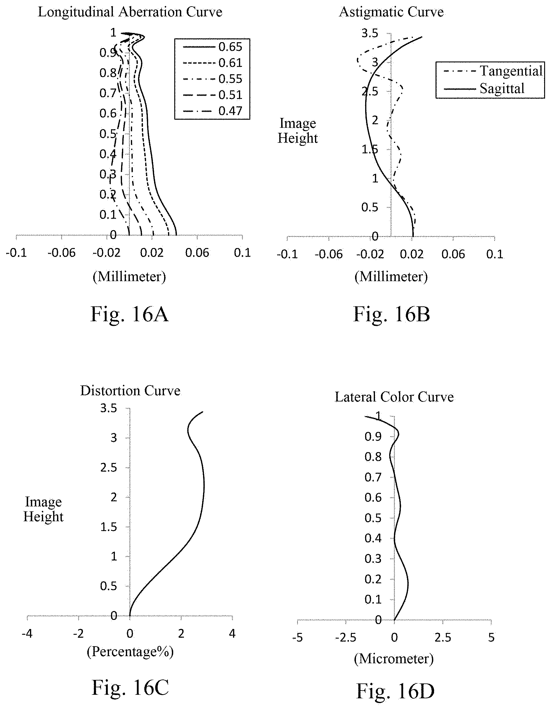
D00013
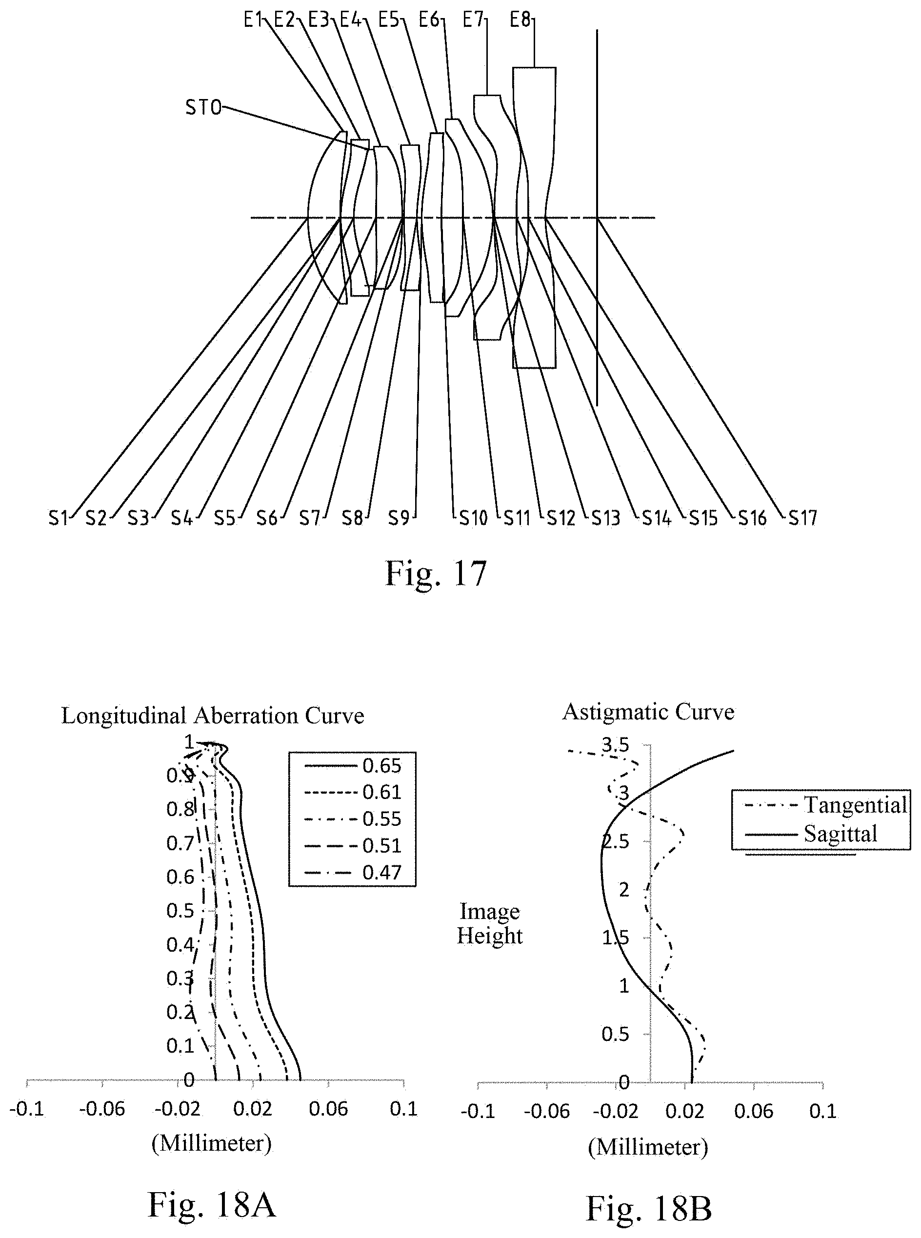
D00014
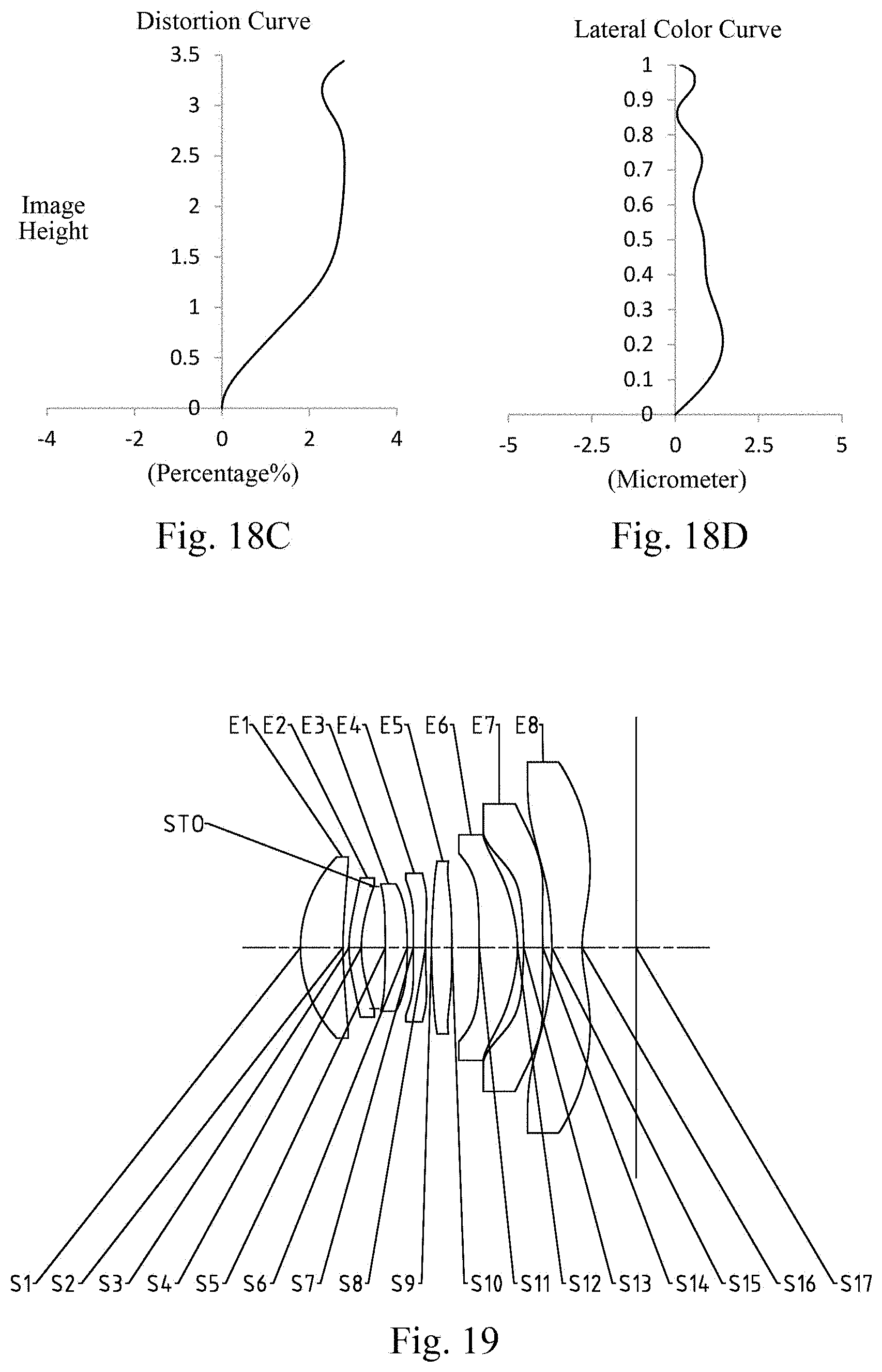
D00015

D00016
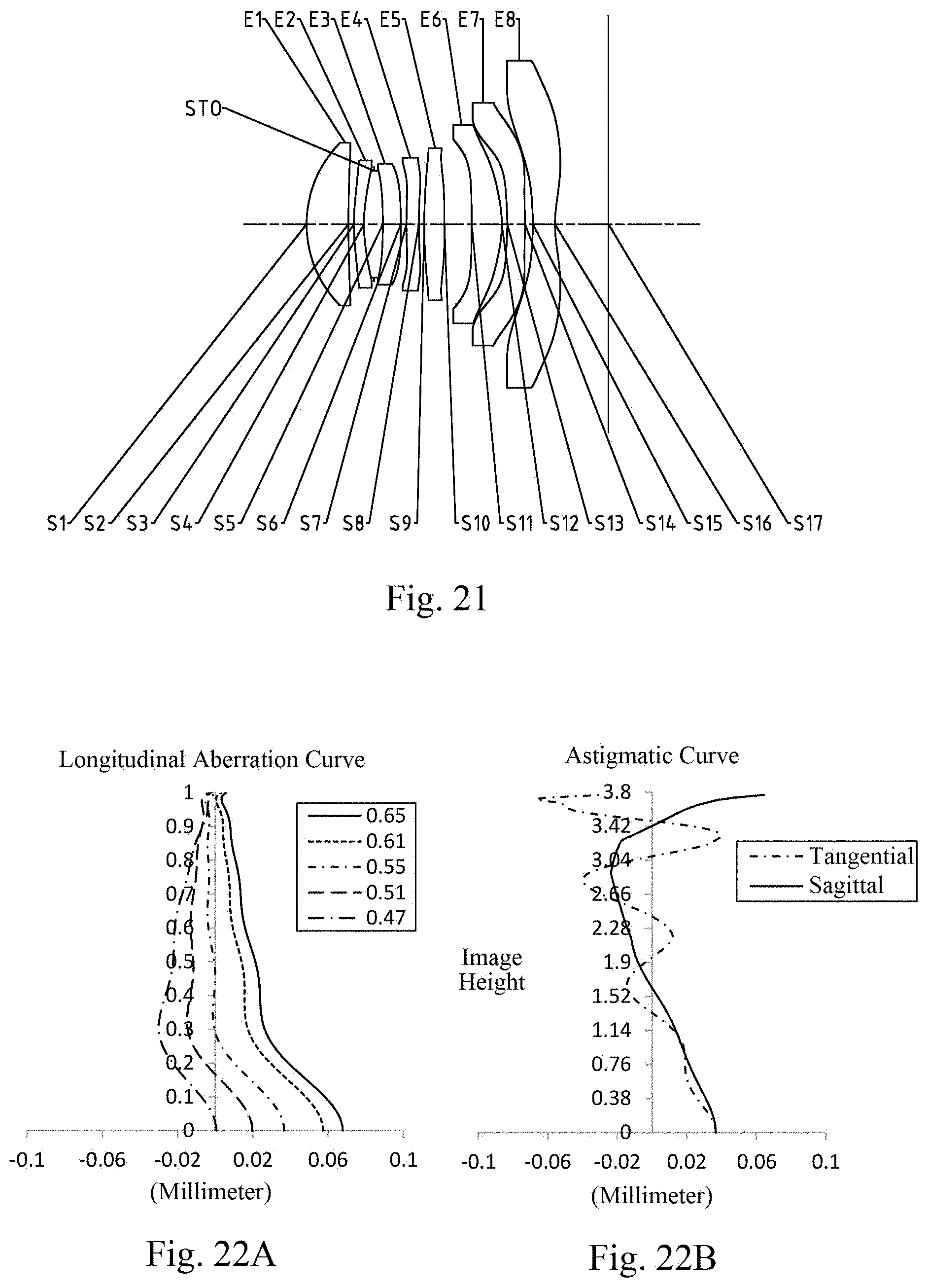
D00017

D00018
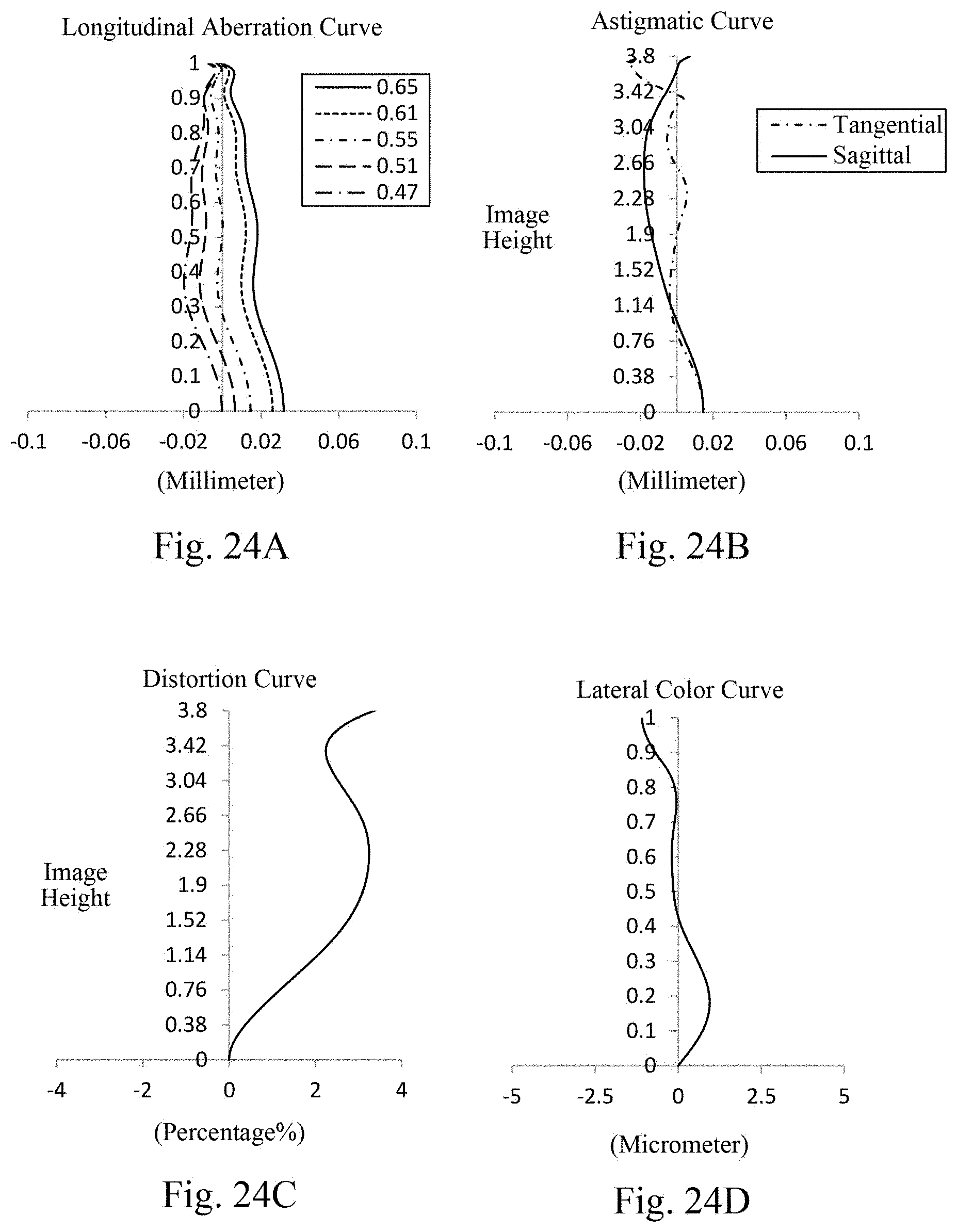
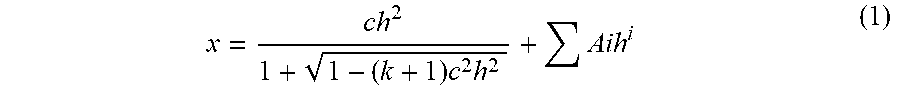
XML
uspto.report is an independent third-party trademark research tool that is not affiliated, endorsed, or sponsored by the United States Patent and Trademark Office (USPTO) or any other governmental organization. The information provided by uspto.report is based on publicly available data at the time of writing and is intended for informational purposes only.
While we strive to provide accurate and up-to-date information, we do not guarantee the accuracy, completeness, reliability, or suitability of the information displayed on this site. The use of this site is at your own risk. Any reliance you place on such information is therefore strictly at your own risk.
All official trademark data, including owner information, should be verified by visiting the official USPTO website at www.uspto.gov. This site is not intended to replace professional legal advice and should not be used as a substitute for consulting with a legal professional who is knowledgeable about trademark law.