Camera Optical Lens
Kind Code
U.S. patent application number 16/679311 was filed with the patent office on 2020-08-06 for camera optical lens. The applicant listed for this patent is AAC Optics Solutions Pte. Ltd.. Invention is credited to Wenbo Hu, Hiroyuki Teraoka, Yanmei Wang, Lei Zhang.
| Application Number | 20200249436 16/679311 |
| Document ID | / |
| Family ID | 1000004498043 |
| Filed Date | 2020-08-06 |


| United States Patent Application | 20200249436 |
| Kind Code | A1 |
| Teraoka; Hiroyuki ; et al. | August 6, 2020 |
CAMERA OPTICAL LENS
Abstract
The present disclosure relates to the field of optical lenses and provides a camera optical lens. The camera optical lens includes, from an object side to an image side: a first lens having a positive refractive power, a second lens having a negative refractive power, a third lens having a negative refractive power, a fourth lens, a fifth lens and a sixth lens. The camera optical lens satisfies following conditions: 2.00R3/R45.00; 1.50R1/d13.00; 0.30R2/R32.00; and 1.02n2/n31.20. The camera optical lens can achieve a high imaging performance while obtaining a low TTL.
| Inventors: | Teraoka; Hiroyuki; (Shenzhen, CN) ; Zhang; Lei; (Shenzhen, CN) ; Wang; Yanmei; (Shenzhen, CN) ; Hu; Wenbo; (Shenzhen, CN) | ||||||||||
| Applicant: |
|
||||||||||
|---|---|---|---|---|---|---|---|---|---|---|---|
| Family ID: | 1000004498043 | ||||||||||
| Appl. No.: | 16/679311 | ||||||||||
| Filed: | November 11, 2019 |
| Current U.S. Class: | 1/1 |
| Current CPC Class: | G02B 13/0045 20130101; G02B 9/62 20130101 |
| International Class: | G02B 13/00 20060101 G02B013/00; G02B 9/62 20060101 G02B009/62 |
Foreign Application Data
| Date | Code | Application Number |
|---|---|---|
| Jan 31, 2019 | CN | 201910096133.6 |
Claims
1. A camera optical lens, comprising, from an object side to an image side: a first lens having a positive refractive power; a second lens having a negative refractive power; a third lens having a negative refractive power; a fourth lens; a fifth lens; and a sixth lens, wherein the camera optical lens satisfies following conditions: 2.00R3/R45.00; 1.50R1/d13.00; 0.30R2/R32.00; and 1.02n2/n31.20, where R3 denotes an on-axis curvature radius of an object side surface of the second lens; R4 denotes an on-axis curvature radius of an image side surface of the second lens; R1 denotes an on-axis curvature radius of an object side surface of the first lens; d1 denotes an on-axis thickness of the first lens; R2 denotes an on-axis curvature radius of an image side surface of the first lens; n2 denotes a refractive index of the second lens; and n3 denotes a refractive index of the third lens.
2. The camera optical lens as described in claim 1, further satisfying a following condition: -13.00R9/R10-3.00, where R9 denotes an on-axis curvature radius of an object side surface of the fifth lens; and R10 denotes an on-axis curvature radius of an image side surface of the fifth lens.
3. The camera optical lens as described in claim 2, further satisfying a following condition: -12.00R9/R10-5.00.
4. The camera optical lens as described in claim 1, further satisfying a following condition: -2.50.ltoreq.f3/f4.ltoreq.0, where f3 denotes a focal length of the third lens; and f4 denotes a focal length of the fourth lens.
5. The camera optical lens as described in claim 4, further satisfying a following condition: -2.00f3/f4<0.
6. The camera optical lens as described in claim 1, further satisfying a following condition: 0.01.ltoreq.d11/TTL.ltoreq.0.20, where d11 denotes an on-axis thickness of the sixth lens; and TTL denotes a total optical length from the object side surface of the first lens to an image plane of the camera optical lens along an optic axis.
7. The camera optical lens as described in claim 6, further satisfying a following condition: 0.04.ltoreq.d11/TTL.ltoreq.0.13.
8. The camera optical lens as described in claim 1, further satisfying a following condition: 0.10.ltoreq.Yc62/TTL.ltoreq.0.55, where Yc62 denotes a perpendicular distance from an arrest point on an image side surface of the sixth lens to an optic axis; and TTL denotes a total optical length from the object side surface of the first lens to an image plane of the camera optical lens along the optic axis.
9. The camera optical lens as described in claim 8, further satisfying a following condition: 0.20.ltoreq.Yc62/TTL.ltoreq.0.30.
10. The camera optical lens as described in claim 1, wherein an FNO of the camera optical lens is smaller than or equal to 2.00.
Description
TECHNICAL FIELD
[0001] The present disclosure relates to the field of optical lens, and more particularly, to a camera optical lens suitable for handheld terminal devices, such as smart phones or digital cameras, and imaging devices, such as monitors or PC lenses.
BACKGROUND
[0002] With the emergence of smart phones in recent years, the demand for miniature camera lens is increasing day by day, but in general the photosensitive devices of camera lens are nothing more than Charge Coupled Device (CCD) or Complementary Metal-Oxide Semiconductor Sensor (CMOS sensor), and as the progress of the semiconductor manufacturing technology makes the pixel size of the photosensitive devices become smaller, plus the current development trend of electronic products towards better functions and thinner and smaller dimensions, miniature camera lenses with good imaging quality therefore have become a mainstream in the market. In order to obtain better imaging quality, the lens that is traditionally equipped in mobile phone cameras adopts a three-piece or four-piece lens structure. Also, with the development of technology and the increase of the diverse demands of users, and as the pixel area of photosensitive devices is becoming smaller and smaller and the requirement of the system on the imaging quality is improving constantly, the five-piece, six-piece and seven-piece lens structures gradually appear in lens designs. There is an urgent need for ultra-thin, wide-angle camera lenses with good optical characteristics and fully corrected chromatic aberration.
BRIEF DESCRIPTION OF DRAWINGS
[0003] Many aspects of the exemplary embodiment can be better understood with reference to the following drawings. The components in the drawings are not necessarily drawn to scale, the emphasis instead being placed upon clearly illustrating the principles of the present disclosure. Moreover, in the drawings, like reference numerals designate corresponding parts throughout the several views.
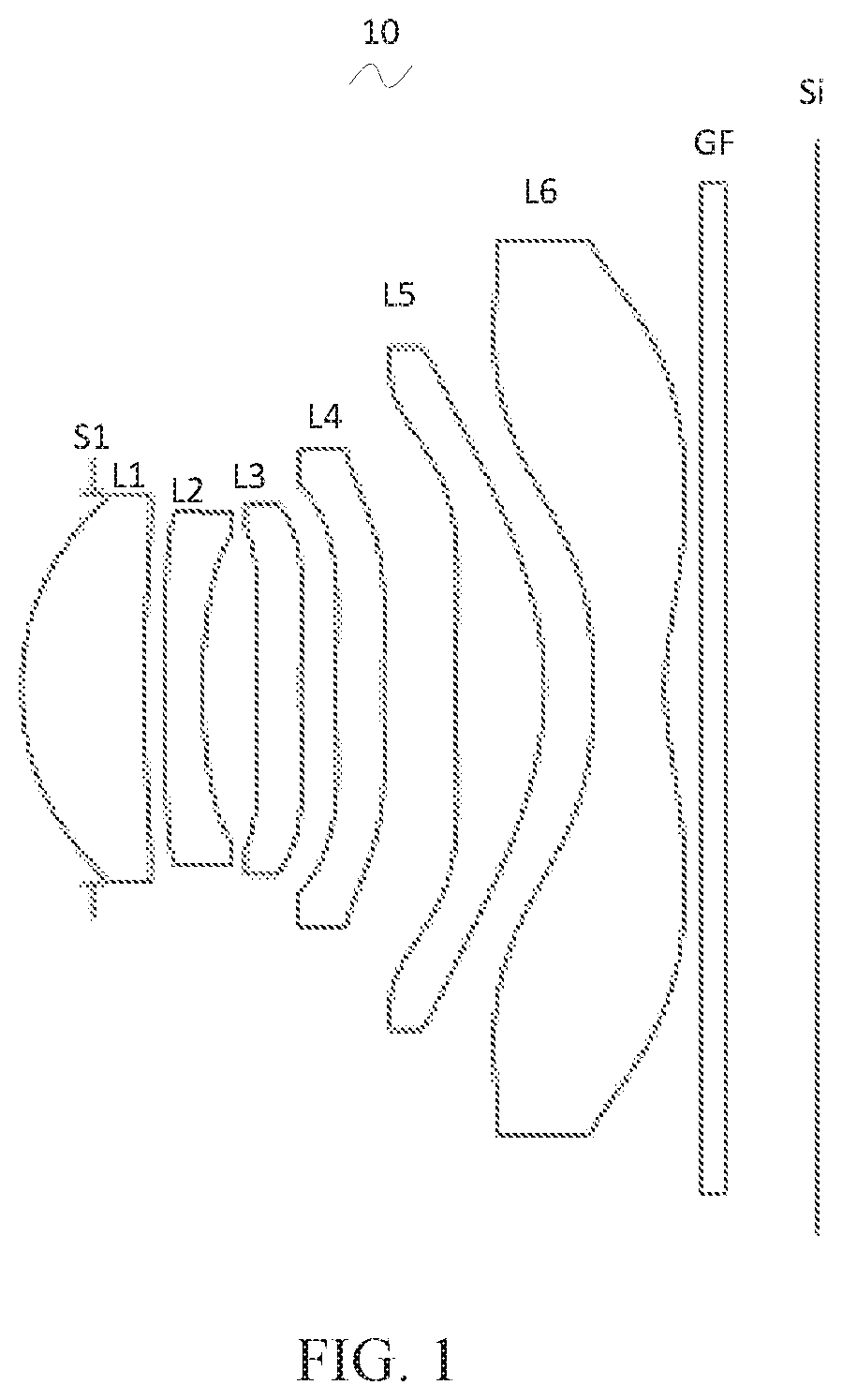
[0004] FIG. 1 is a schematic diagram of a structure of a camera optical lens in accordance with Embodiment 1 of the present disclosure;
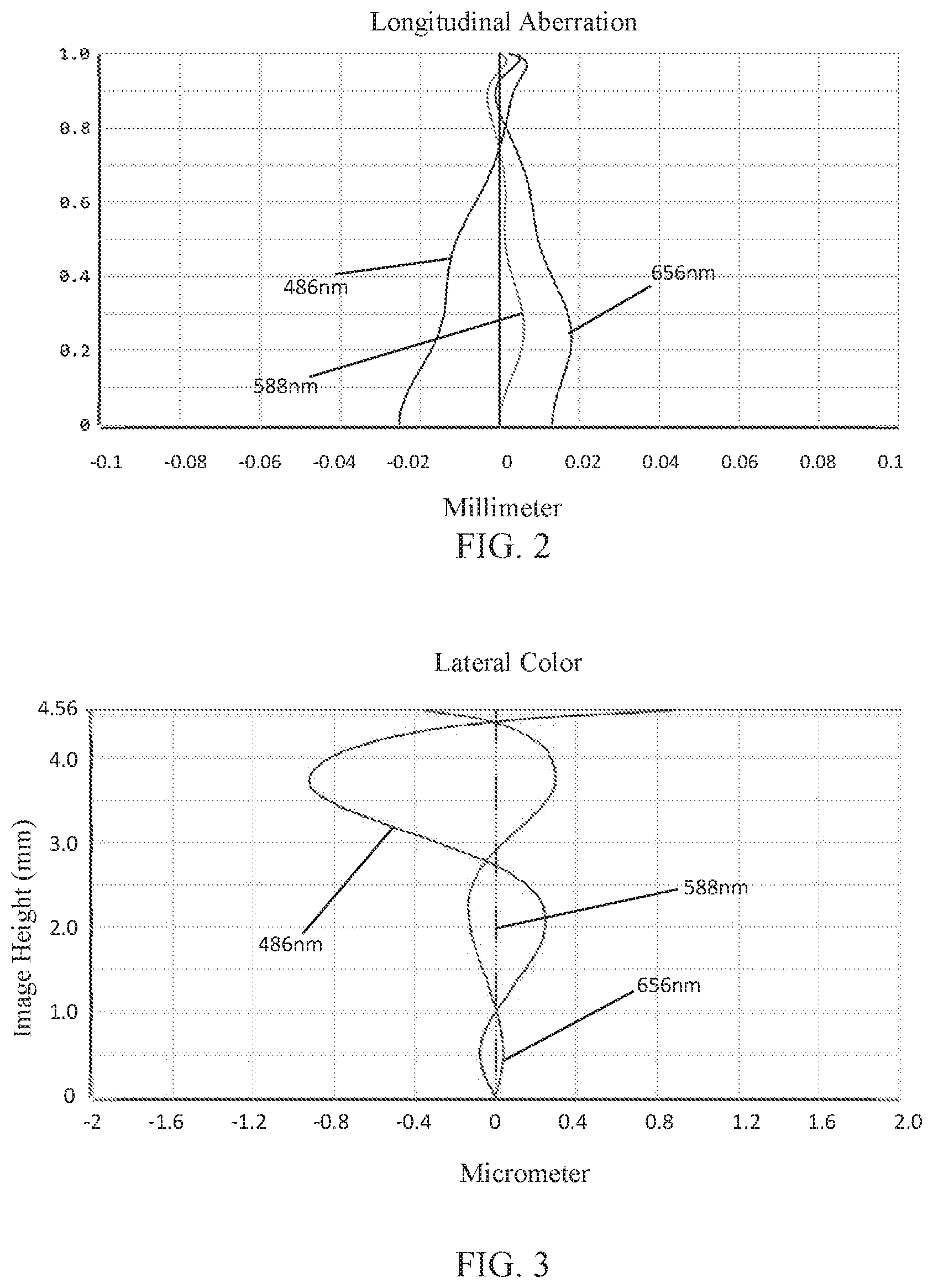
[0005] FIG. 2 is a schematic diagram of a longitudinal aberration of the camera optical lens shown in FIG. 1;
[0006] FIG. 3 is a schematic diagram of a lateral color of the camera optical lens shown in FIG. 1;
[0007] FIG. 4 is a schematic diagram of a field curvature and a distortion of the camera optical lens shown in FIG. 1;
[0008] FIG. 5 is a schematic diagram of a structure of a camera optical lens in accordance with Embodiment 2 of the present disclosure;
[0009] FIG. 6 is a schematic diagram of a longitudinal aberration of the camera optical lens shown in FIG. 5;
[0010] FIG. 7 is a schematic diagram of a lateral color of the camera optical lens shown in FIG. 5;
[0011] FIG. 8 is a schematic diagram of a field curvature and a distortion of the camera optical lens shown in FIG. 5;
[0012] FIG. 9 is a schematic diagram of a structure of a camera optical lens in accordance with Embodiment 3 of the present disclosure;
[0013] FIG. 10 is a schematic diagram of a longitudinal aberration of the camera optical lens shown in FIG. 9;
[0014] FIG. 11 is a schematic diagram of a lateral color of the camera optical lens shown in FIG. 9; and
[0015] FIG. 12 is a schematic diagram of a field curvature and a distortion of the camera optical lens shown in FIG. 9.
DESCRIPTION OF EMBODIMENTS
[0016] The present disclosure will hereinafter be described in detail with reference to several exemplary embodiments. To make the technical problems to be solved, technical solutions and beneficial effects of the present disclosure more apparent, the present disclosure is described in further detail together with the figure and the embodiments. It should be understood the specific embodiments described hereby is only to explain the disclosure, not intended to limit the disclosure.
Embodiment 1
[0017] Referring to the FIG. 1, the present disclosure provides a camera optical lens 10. FIG. 1 shows the camera optical lens 10 according to Embodiment 1 of the present disclosure. The camera optical lens 10 includes 6 lenses. Specifically, the camera optical lens 10 includes, from an object side to an image side, an aperture S1, a first lens L1, a second lens L2, a third lens L3, a fourth lens L4, a fifth lens L5 and a sixth lens L6. An optical element such as an optical filter GF can be arranged between the sixth lens L6 and an image plane Si.
[0018] The first lens L1, the second lens L2, the third lens L3, the fourth lens L4, the fifth lens L5 and the sixth lens L6 are all made of a plastic material.
[0019] The first lens L1 has a positive refractive power. The second lens L2 has a negative refractive power, and the third lens L3 has a negative refractive power.
[0020] An on-axis curvature radius of an object side surface of the second lens L2 is defined as R3. An on-axis curvature radius of an image side surface of the second lens L2 is defined as R4. An on-axis curvature radius of an object side surface of the first lens L1 is defined as R1. An on-axis thickness of the first lens L1 is defined as d1. An on-axis curvature radius of an image side surface of the first lens L1 is defined as R2. A refractive index of the second lens L2 is defined as n2. A refractive index of the third lens L3 is defined as n3. The camera optical lens 10 should satisfy conditions (1)-(4):
2.00.ltoreq.R3/R4.ltoreq.5.00 (1);
1.50.ltoreq.R1/d1.ltoreq.3.00 (2);
0.30.ltoreq.R2/R3.gtoreq.2.00 (3); and
1.02.ltoreq.n2/n3.ltoreq.1.20 (4).
[0021] The condition (1) specifies a shape of the second lens L2. Out of the range of the condition (1), it is difficult to achieve miniaturization in an FNO bright state.
[0022] The condition (2) specifies a ratio of the on-axis curvature radius of the object side surface of the first lens L1 and the on-axis thickness of the first lens L1. Out of the range of the condition (2), it is difficult to achieve miniaturization in the FNO bright state.
[0023] The condition (3) specifies a ratio of the on-axis curvature radius of the image side surface of the first lens L1 and the on-axis curvature radius of the object side surface of the second lens L2. The ratio is reasonably controlled in such a manner that the second lens L2 can effectively correct the system aberration. Out of the range of the condition (3), it is difficult to achieve an excellent imaging performance in the FNO bright state.
[0024] The condition (4) specifies a ratio of the refractive index of the second lens L2 and the refractive index of the third lens L3. Within the range of the condition (4), the camera optical lens 10 can better correct the system aberration, so as to satisfy the demand for the high-performance imaging.
[0025] A total optical length from the object side surface of the first lens L1 to an image plane of the camera optical lens 10 along an optic axis is defined as TTL. When the on-axis thickness and the curvature radius of the camera optical lens 10 of the present disclosure satisfy the above conditions, the camera optical lens 10 will have the advantage of high performance and satisfy the design requirement of wide angle and a low TTL.
[0026] In this embodiment, the object side surface of the first lens L1 is convex in the paraxial region, and the image side surface of the first lens L1 is concave in the paraxial region, and the first lens L1 has a positive refractive power. The object side surface of the second lens L2 is convex in the paraxial region, the image side surface of the second lens L2 is concave in the paraxial region, and the second lens L2 has a negative refractive power. An object side surface of the third lens L3 is convex in the paraxial region, an image side surface of the third lens L3 is concave in the paraxial region, and the third lens L3 has a negative refractive power. An object side surface of the fourth lens L4 is convex in the paraxial region, an image side surface of the fourth lens L4 is concave in the paraxial region, and the fourth lens L4 has a positive refractive power. An object side surface of the fifth lens L5 is convex in the paraxial region, an image side surface of the fifth lens L5 is convex in the paraxial region, and the fifth lens L5 has a positive refractive power. An object side surface of the sixth lens L6 is concave in the paraxial region, an image side surface of the sixth lens L6 is concave in the paraxial region, and the sixth lens L6 has a negative refractive power.
[0027] An on-axis curvature radius of the object side surface of the fifth lens L5 is defined as R9, and an on-axis curvature radius of the image side surface of the fifth lens L5 is defined as R10. The camera optical lens 10 should satisfy a following condition (5):
-13.00.ltoreq.R9/R10.ltoreq.-3.00 (5).
[0028] The condition (5) specifies a shape of the fifth lens L5. Out of the range of the condition (5), it is difficult to achieve miniaturization in the FNO bright state.
[0029] Further, it is preferable to set a numerical range of the condition (5) to a numerical range of a following condition (5-A).
-12.00.ltoreq.R9/R10.ltoreq.-5.00 (5-A).
[0030] A focal length of the third lens L3 is f3, and a focal length of the fourth lens L4 is f4. The camera optical lens 10 should satisfy a following condition (6):
-2.50.ltoreq.f3/f4.ltoreq. (6).
[0031] The condition (6) specifies a ratio of the focal length f3 of the third lens L3 and the focal length f4 of the fourth lens L4. The refractive power is reasonably assigned in such a manner that the system has a better imaging quality and lower sensitivity.
[0032] Further, it is preferable to set a numerical range of the condition (6) to a numerical range of a following condition (6-A).
-2.00.ltoreq.f3/f4.ltoreq.0 (6-A).
[0033] An on-axis thickness of the sixth lens L6 is defined as d11. The camera optical lens 10 should satisfy a following condition (7):
0.01.ltoreq.d11/TTL.ltoreq.0.20 (7).
[0034] The condition (7) specifies a ratio of the on-axis thickness d11 of the sixth lens L6 and the total optical length TTL. Out of the range of the condition (7), it is difficult to achieve miniaturization in the FNO bright state.
[0035] Further, it is preferable to set a numerical range of the condition (7) to a numerical range of a following condition (7-A):
0.04.ltoreq.d11/TTL.ltoreq.0.13 (7-A).
[0036] A perpendicular distance from an arrest point on the image side surface of the sixth lens L6 to the optic axis is Yc62. The camera optical lens 10 should satisfy a following condition (8):
0.10.ltoreq.Yc62/TTL.ltoreq.0.55 (8).
[0037] The condition (8) specifies a ratio of a position of the arrest point of the sixth lens L6 and the total optical length TTL. Out of the range of the condition (8), it is difficult to correct an aberration and a distortion of the camera optical lens 10.
[0038] Further, it is preferable to set a numerical range of the condition (8) to a numerical range of a following condition (8-A):
0.20.ltoreq.Yc62/TTL.ltoreq.0.30 (8-A).
[0039] An FNO of the camera optical lens 10 is smaller than or equal to 2.00. The FNO is an F number of the camera optical lens. When this condition is satisfied, the camera optical lens 10 will have a good brightness, so as to satisfy the demand for a large aperture and also make night imaging effect better.
[0040] With such design, the total optical length TTL of the camera optical lens 10 can be made as short as possible, and thus the characteristics of wide-angle and miniaturization can be maintained while satisfying the demand for a large aperture.
[0041] In the following, examples will be used to describe the camera optical lens 10 of the present disclosure. The symbols recorded in each example will be described as follows. The focal length, on-axis distance, curvature radius, on-axis thickness, inflexion point position, and arrest point position are all in units of mm. The FOV (field of view) is in a unit of .degree..
[0042] f: focal length of the camera optical lens 10;
[0043] f1: focal length of the first lens L1;
[0044] f2: focal length of the second lens L2;
[0045] f3: focal length of the third lens L3;
[0046] f4: focal length of the fourth lens L4;
[0047] FNO: F number;
[0048] 2.omega.: FOV (field of view);
[0049] S1: aperture;
[0050] R: curvature radius of an optical surface, a central curvature radius for a lens;
[0051] R1: curvature radius of the object side surface of the first lens L1;
[0052] R2: curvature radius of the image side surface of the first lens L1;
[0053] R3: curvature radius of the object side surface of the second lens L2;
[0054] R4: curvature radius of the image side surface of the second lens L2;
[0055] R5: curvature radius of the object side surface of the third lens L3;
[0056] R6: curvature radius of the image side surface of the third lens L3;
[0057] R7: curvature radius of the object side surface of the fourth lens L4;
[0058] R8: curvature radius of the image side surface of the fourth lens L4;
[0059] R9: curvature radius of the object side surface of the fifth lens L5;
[0060] R10: curvature radius of the image side surface of the fifth lens L5;
[0061] R11: curvature radius of the object side surface of the sixth lens L6;
[0062] R12: curvature radius of the image side surface of the sixth lens L6;
[0063] R13: curvature radius of an object side surface of the optical filter GF;
[0064] R14: curvature radius of an image side surface of the optical filter GF;
[0065] d: on-axis thickness of a lens and an on-axis distance between lenses;
[0066] d0: on-axis distance from the aperture S1 to the object side surface of the first lens L1;
[0067] d1: on-axis thickness of the first lens L1;
[0068] d2: on-axis distance from the image side surface of the first lens L1 to the object side surface of the second lens L2;
[0069] d3: on-axis thickness of the second lens L2;
[0070] d4: on-axis distance from the image side surface of the second lens L2 to the object side surface of the third lens L3;
[0071] d5: on-axis thickness of the third lens L3;
[0072] d6: on-axis distance from the image side surface of the third lens L3 to the object side surface of the fourth lens L4;
[0073] d7: on-axis thickness of the fourth lens L4;
[0074] d8: on-axis distance from the image side surface of the fourth lens L4 to the object side surface of the fifth lens L5;
[0075] d9: on-axis thickness of the fifth lens L5;
[0076] d10: on-axis distance from the image side surface of the fifth lens L5 to the object side surface of the sixth lens L6;
[0077] d11: on-axis thickness of the sixth lens L6;
[0078] d12: on-axis distance from the image side surface of the sixth lens L6 to the object side surface of the optical filter GF;
[0079] d13: on-axis thickness of the optical filter GF;
[0080] d14: on-axis distance from the image side surface of the optical filter GF to the image plane;
[0081] nd: refractive index of d line;
[0082] nd1: refractive index of d line of the first lens L1;
[0083] nd2: refractive index of d line of the second lens L2;
[0084] nd3: refractive index of d line of the third lens L3;
[0085] nd4: refractive index of d line of the fourth lens L4;
[0086] nd5: refractive index of d line of the fifth lens L5;
[0087] nd6: refractive index of d line of the sixth lens L6;
[0088] ndg: refractive index of d line of the optical filter GF;
[0089] vd: abbe number;
[0090] v1: abbe number of the first lens L1;
[0091] v2: abbe number of the second lens L2;
[0092] v3: abbe number of the third lens L3;
[0093] v4: abbe number of the fourth lens L4;
[0094] v5: abbe number of the fifth lens L5;
[0095] v6: abbe number of the sixth lens L6;
[0096] vg: abbe number of the optical filter GF.
[0097] TTL: optical length (the total optical length from the object side surface of the first lens to the image plane of the camera optical lens along the optic axis) in mm.
[0098] LB: on-axis distance from the image side surface of the sixth lens L6 to the image plane (including a thickness of the optical filter GF);
[0099] IH: Image Height
y=(x.sup.2/R)/[1+{1-(k+1)(x.sup.2/R.sup.2)}.sup.1/2]+A4x.sup.4+A6x.sup.6- +A8x.sup.8+A10x.sup.10+A12x.sup.12+A14x.sup.14+A1 6x.sup.16+A18x.sup.18+A20x.sup.20 (9)
[0100] Here, k is a conic coefficient, A4, A6, A8, A10, Al2, A14, A16, A18, A20 are aspherical surface coefficients, x is a perpendicular distance between a point on an aspheric surface curve and the optic axis, and y is an aspherical surface depth (a perpendicular distance between the point on an aspherical surface having a distance of x from the optic axis and a tangent plane tangent to an apex on the aspherical surface optic axis).
[0101] For convenience, the aspheric surface of each lens surface uses the aspheric surfaces shown in the above formula (9). However, the present disclosure is not limited to the aspherical polynomials form shown in the formula (9).
[0102] Preferably, inflexion points and/or arrest points can be arranged on the object side surface and/or image side surface of the lens, so as to satisfy the demand for the high quality imaging. The description below can be referred to for specific implementations.
[0103] Design data of the camera optical lens 10 in Embodiment 1 of the present disclosure is shown in Tables 1 and 2.
TABLE-US-00001 TABLE 1 R d nd vd S1 .infin. d0= -0.600 R1 2.124 d1= 1.025 nd1 1.5439 .nu.1 55.95 R2 8.951 d2= 0.171 R3 12.166 d3= 0.323 nd2 1.6713 .nu.2 19.24 R4 4.589 d4= 0.448 R5 12.957 d5= 0.375 nd3 1.5835 .nu.3 28.00 R6 10.177 d6= 0.296 R7 8.118 d7= 0.400 nd4 1.6150 .nu.4 25.92 R8 10.930 d8= 0.612 R9 23.466 d9= 0.738 nd5 1.5439 .nu.5 55.95 R10 -2.480 d10= 0.411 R11 -5.595 d11= 0.598 nd6 1.5352 .nu.6 56.12 R12 2.378 d12= 0.300 R13 .infin. d13= 0.210 ndg 1.5168 .nu.g 64.17 R14 .infin. d14= 0.770
[0104] Table 2 shows aspherical surface data of each lens in the camera optical lens 10 in Embodiment 1 of the present disclosure.
TABLE-US-00002 TABLE 2 Conic coefficient Aspherical Surface coefficient k A4 A6 A8 A10 A12 R1 1.5342E-02 -2.3362E-04 9.0797E-04 -2.3643E-03 3.0077E-03 -1.9987E-03 R2 4.5883E+00 -2.6471E-02 1.2687E-02 -4.0646E-03 4.8577E-04 -4.9378E-05 R3 -3.8260E+00 -4.6266E-02 4.0360E-02 -1.4842E-02 3.1862E-03 -3.8028E-04 R4 2.8098E-01 -2.2856E-02 2.9997E-02 7.1762E-03 -2.3541E-02 2.0709E-02 R5 2.1445E+01 -5.0618E-02 3.4937E-02 -6.0403E-02 5.8961E-02 -3.5912E-02 R6 8.9109E+00 -6.8079E-02 5.0880E-02 -5.6032E-02 3.6467E-02 -1.4847E-02 R7 1.1988E+00 -8.8173E-02 2.9236E-02 -8.4161E-03 -3.0498E-03 3.7120E-03 R8 -6.1958E+00 -7.2320E-02 1.2017E-02 2.9259E-03 -5.5053E-03 3.0474E-03 R9 0.0000E+00 -1.0825E-03 -1.7555E-02 1.0194E-02 -4.8260E-03 1.5208E-03 R10 -3.0660E+00 3.1185E-02 -2.8604E-02 1.4092E-02 -4.4012E-03 8.9663E-04 R11 1.2494E-02 -6.7456E-02 1.8386E-02 -1.0328E-03 -2.0299E-04 3.3549E-05 R12 -9.5226E+00 -5.1549E-02 1.8725E-02 -4.9930E-03 9.3779E-04 -1.2324E-04 Aspherical Surface coefficient A14 A16 A18 A20 R1 6.5584E-04 -9.1833E-05 0.0000E+00 0.0000E+00 R2 4.1440E-05 -1.4318E-05 0.0000E+00 0.0000E+00 R3 1.4634E-04 -2.3837E-05 0.0000E+00 0.0000E+00 R4 -8.7601E-03 1.6903E-03 0.0000E+00 0.0000E+00 R5 1.1721E-02 -1.6126E-03 0.0000E+00 0.0000E+00 R6 3.1509E-03 -2.5833E-04 0.0000E+00 0.0000E+00 R7 -1.2395E-03 1.3660E-04 0.0000E+00 0.0000E+00 R8 -7.1103E-04 6.0276E-05 0.0000E+00 0.0000E+00 R9 -3.0237E-04 3.7630E-05 -2.6802E-06 8.2569E-08 R10 -1.1513E-04 8.6503E-06 -3.2579E-07 3.9621E-09 R11 -1.0253E-06 -1.3185E-07 1.1994E-08 -2.9666E-10 R12 1.0948E-05 -6.2128E-07 2.0259E-08 -2.8797E-10
[0105] Tables 3 and 4 show design data of the inflection point and the arrest point of each lens in the camera optical lens 10 according to Embodiment 1 of the present disclosure. P1R1 and P1R2 represent the object side surface and the image side surface of the first lens L1, respectively. P2R1 and P2R2 represent the object side surface and the image side surface of the second lens L2, respectively. P3R1 and P3R2 represent the object side surface and the image side surface of the third lens L3, respectively. P4R1 and P4R2 represent the object side surface and the image side surface of the fourth lens L4, respectively. P5R1 and P5R2 respectively represent the object side surface and the image side surface of the fifth lens L5. P6R1, P6R2 represent the object side surface and the image side surface of the sixth lens L6, respectively. An "inflection point position" field corresponds to data that are perpendicular distances from the inflection point set by each lens surface to the optic axis of the camera optical lens 10. The "arrest point position" field corresponds to data that are perpendicular distances from the arrest point of each lens surface to the optic axis of the camera optical lens 10.
TABLE-US-00003 TABLE 3 Number of Inflexion point Inflexion point inflexion points position 1 position 2 P1R1 1 1.605 P1R2 1 1.015 P2R1 0 P2R2 0 P3R1 1 0.405 P3R2 1 0.405 P4R1 1 0.365 P4R2 2 0.335 1.675 P5R1 2 0.565 2.125 P5R2 2 2.015 2.345 P6R1 2 1.605 3.315 P6R2 2 0.685 3.395
TABLE-US-00004 TABLE 4 Number of arrest points Arrest point position P1R1 0 P1R2 1 1.495 P2R1 0 P2R2 0 P3R1 1 0.695 P3R2 1 0.715 P4R1 1 0.655 P4R2 1 0.585 P5R1 1 0.885 P5R2 0 P6R1 1 2.985 P6R2 1 1.635
[0106] FIG. 2 and FIG. 3 illustrate a longitudinal aberration and a lateral color of light with wavelengths of 486 nm, 588 nm, and 656 nm after passing the camera optical lens 10 according to Embodiment 1, respectively. FIG. 4 illustrates a field curvature and a distortion of light with a wavelength of 588 nm after passing the camera optical lens 10 according to Embodiment 1, in which a field curvature S is a field curvature in a sagittal direction and T is a field curvature in a tangential direction.
[0107] Table 13 which is shown later shows various values of Embodiments 1, 2 and 3 and values corresponding to parameters which are specified in the above conditions.
[0108] As shown in Table 13, Embodiment 1 satisfies the above conditions.
[0109] In this embodiment, the entrance pupil diameter ENPD of the camera optical lens is 3.272 mm. The image height of 1.0H is 4.560 mm. The FOV 2.omega. is 78.295.degree. in a diagonal direction. Thus, the camera optical lens has a wide-angle and is ultra-thin. Its on-axis and off-axis chromatic aberrations are fully corrected, thereby achieving excellent optical characteristics.
Embodiment 2
[0110] Embodiment 2 is basically the same as Embodiment 1 and involves symbols having the same meanings as Embodiment 1, and only differences therebetween will be described in the following.
[0111] Table 5 and Table 6 show design data of a camera optical lens 20 in Embodiment 2 of the present disclosure.
TABLE-US-00005 TABLE 5 R d nd .nu.d S1 .infin. d0= -0.600 R1 2.137 d1= 0.930 nd1 1.5439 .nu.1 55.95 R2 11.984 d2= 0.121 R3 7.765 d3= 0.300 nd2 1.6713 .nu.2 19.24 R4 3.543 d4= 0.552 R5 31.078 d5= 0.421 nd3 1.5835 .nu.3 28.00 R6 21.515 d6= 0.360 R7 5.222 d7= 0.336 nd4 1.6150 .nu.4 25.92 R8 5.179 d8= 0.560 R9 16.860 d9= 0.878 nd5 1.5439 .nu.5 55.95 R10 -2.476 d10= 0.592 R11 -5.503 d11= 0.351 nd6 1.5352 .nu.6 56.12 R12 2.364 d12= 0.300 R13 .infin. d13= 0.210 ndg 1.5168 .nu.g 64.17 R14 .infin. d14= 0.690
[0112] Table 6 shows aspherical surface data of each lens in the camera optical lens 20 in Embodiment 2 of the present disclosure.
TABLE-US-00006 TABLE 6 Conic coefficient Aspherical Surface coefficient k A4 A6 A8 A10 A12 R1 2.6021E-02 2.9107E-04 1.4280E-03 -1.9057E-03 1.9303E-03 -1.1475E-03 R2 1.7994E+01 -2.7383E-02 2.2984E-02 -1.2122E-02 3.6250E-03 -5.7212E-04 R3 4.4297E-01 -4.9101E-02 4.8734E-02 -2.6862E-02 1.0613E-02 -2.7912E-03 R4 1.5047E+00 -2.6830E-02 2.9481E-02 2.5839E-03 -2.5160E-02 2.7364E-02 R5 0.0000E+00 -3.5105E-02 1.5118E-02 -3.7096E-02 4.7234E-02 -4.2390E-02 R6 -5.2834E+01 -4.8495E-02 2.3006E-02 -1.8153E-02 3.4636E-03 2.3283E-03 R7 -1.3608E+01 -7.9479E-02 2.2187E-02 -1.9282E-03 -4.0780E-03 2.0926E-03 R8 -3.0153E+01 -5.4532E-02 -4.4365E-04 9.5741E-03 -6.3925E-03 2.1533E-03 R9 0.0000E+00 4.8283E-03 -1.4875E-02 5.8803E-03 -2.0804E-03 4.8386E-04 R10 -6.5314E+00 1.6667E-02 -1.4202E-02 6.7479E-03 -2.4259E-03 5.7889E-04 R11 -4.2179E-01 -5.7775E-02 1.7352E-02 -2.8784E-03 4.6227E-04 -6.7646E-05 R12 -1.0614E+01 -5.0421E-02 1.7020E-02 -4.2617E-03 7.4376E-04 -8.9101E-05 Aspherical Surface coefficient A14 A16 A18 A20 R1 3.6415E-04 -5.3279E-05 0.0000E+00 0.0000E+00 R2 4.1239E-05 -4.0855E-06 0.0000E+00 0.0000E+00 R3 5.5992E-04 -5.3348E-05 0.0000E+00 0.0000E+00 R4 -1.3038E-02 2.5979E-03 0.0000E+00 0.0000E+00 R5 2.4179E-02 -8.0785E-03 1.2094E-03 0.0000E+00 R6 -1.6757E-03 3.1884E-04 0.0000E+00 0.0000E+00 R7 -4.6908E-04 4.0271E-05 0.0000E+00 0.0000E+00 R8 -3.5383E-04 2.2667E-05 0.0000E+00 0.0000E+00 R9 -6.1896E-05 3.9513E-06 -8.6289E-08 -1.0170E-09 R10 -8.6159E-05 7.7649E-06 -3.9526E-07 8.8913E-09 R11 6.9471E-06 -4.3896E-07 1.5322E-08 -2.2669E-10 R12 7.0546E-06 -3.4801E-07 9.6036E-09 -1.1218E-10
[0113] Design data of the camera optical lens 20 in Embodiment 2 of the present disclosure is shown in Tables 7 and 8.
TABLE-US-00007 TABLE 7 Number of Inflexion point Inflexion point Inflexion point inflexion points position 1 position 2 position 3 P1R1 0 P1R2 1 1.355 P2R1 0 P2R2 0 P3R1 1 0.295 P3R2 2 0.295 1.545 P4R1 1 0.455 P4R2 2 0.475 1.815 P5R1 3 0.735 2.255 3.125 P5R2 0 P6R1 1 1.755 P6R2 2 0.665 3.455
TABLE-US-00008 TABLE 8 Number of Arrest point Arrest point arrest points position 1 position 2 P1R1 0 P1R2 0 P2R1 0 P2R2 0 P3R1 1 0.495 P3R2 1 0.525 P4R1 1 0.825 P4R2 1 0.855 P5R1 2 1.115 2.695 P5R2 0 P6R1 1 3.225 P6R2 2 1.535 3.895
[0114] FIG. 6 and FIG. 7 illustrate a longitudinal aberration and a lateral color of light with wavelengths of 486 nm, 588 nm, and 656 nm after passing the camera optical lens 20 according to Embodiment 2, respectively. FIG. 8 illustrates a field curvature and a distortion of light with a wavelength of 588 nm after passing the camera optical lens 20 according to Embodiment 2.
[0115] As shown in Table 13, Embodiment 2 satisfies the above conditions.
[0116] In this embodiment, the entrance pupil diameter ENPD of the camera optical lens is 3.231 mm. The image height of 1.0H is 4.560 mm. The FOV 2.omega. is 76.117.degree. in a diagonal direction. Thus, the camera optical lens has a wide-angle and is ultra-thin. Its on-axis and off-axis chromatic aberrations are fully corrected, thereby achieving excellent optical characteristics
Embodiment 3
[0117] Embodiment 3 is basically the same as Embodiment 1 and involves symbols having the same meanings as Embodiment 1, and only differences therebetween will be described in the following.
[0118] Table 9 and Table 10 show design data of a camera optical lens 30 in Embodiment 3 of the present disclosure.
TABLE-US-00009 TABLE 9 R d nd .nu.d S1 .infin. d0= -0.600 R1 2.233 d1= 1.143 nd1 1.5439 .nu.1 55.95 R2 12.456 d2= 0.169 R3 26.071 d3= 0.301 nd2 1.6713 .nu.2 19.24 R4 5.547 d4= 0.574 R5 40.494 d5= 0.429 nd3 1.5835 .nu.3 28.00 R6 30.538 d6= 0.292 R7 15.392 d7= 0.450 nd4 1.6150 .nu.4 25.92 R8 15.222 d8= 0.611 R9 14.415 d9= 0.918 nd5 1.5439 .nu.5 55.95 R10 -2.703 d10= 0.386 R11 -5.914 d11= 0.618 nd6 1.5352 .nu.6 56.12 R12 2.408 d12= 0.300 R13 .infin. d13= 0.210 ndg 1.5168 .nu.g 64.17 R14 .infin. d14= 0.787
[0119] Table 10 shows aspherical surface data of each lens in the camera optical lens 30 in Embodiment 3 of the present disclosure.
TABLE-US-00010 TABLE 10 Conic coefficient Aspherical Surface coefficient k A4 A6 A8 A10 A12 R1 2.9030E-02 1.4761E-04 -2.3134E-04 2.7074E-04 -5.1945E-05 -1.2445E-04 R2 1.3194E+01 -2.1548E-02 8.7901E-03 -2.6806E-03 8.5707E-04 -5.6714E-04 R3 9.7078E+01 -3.7315E-02 3.1277E-02 -1.1104E-02 2.7491E-03 -7.3260E-04 R4 8.2331E-01 -1.5747E-02 2.4598E-02 8.8028E-04 -1.2717E-02 1.2557E-02 R5 0.0000E+00 -3.4133E-02 1.1764E-02 -2.5090E-02 2.1812E-02 -1.2573E-02 R6 4.9372E+01 -5.0785E-02 2.9761E-02 -3.4825E-02 2.1648E-02 -8.5870E-03 R7 -9.0509E+00 -7.8858E-02 2.7288E-02 -1.2535E-02 1.8232E-03 7.2242E-04 R8 -6.1684E+00 -6.6567E-02 1.3032E-02 -3.0453E-04 -2.5963E-03 1.5640E-03 R9 0.0000E+00 -7.3317E-03 -9.1607E-03 4.2998E-03 -1.8352E-03 5.4120E-04 R10 -2.5654E+00 2.7484E-02 -2.0997E-02 8.8177E-03 -2.5845E-03 5.3772E-04 R11 1.0313E-01 -6.1907E-02 1.8227E-02 -2.9646E-03 6.3356E-04 -1.3444E-04 R12 -9.1429E+00 -4.3707E-02 1.5038E-02 -3.7717E-03 6.7475E-04 -8.4283E+05 Aspherical Surface coefficient A14 A16 A18 A20 R1 7.5004E-05 -1.6823E-05 0.0000E+00 0.0000E+00 R2 2.0019E-04 -2.5581E-05 0.0000E+00 0.0000E+00 R3 2.6929E-04 -3.1919E-05 0.0000E+00 0.0000E+00 R4 -5.6226E-03 1.1007E-03 0.0000E+00 0.0000E+00 R5 4.1111E-03 -7.1492E-04 4.5267E-05 0.0000E+00 R6 1.8891E-03 -1.7637E-04 0.0000E+00 0.0000E+00 R7 -2.5990E-04 1.5989E-05 0.0000E+00 0.0000E+00 R8 -3.5246E-04 2.8155E-05 0.0000E+00 0.0000E+00 R9 -9.8421E-05 1.0843E-05 -6.5093E-07 1.5657E-08 R10 -7.3219E-05 5.9050E-06 -2.4265E-07 3.4975E-09 R11 1.8132E-05 -1.4133E-06 5.9159E-08 -1.0385E-09 R12 7.0619E-06 -3.7448E-07 1.1294E-08 -1.4698E-10
[0120] Design data of the camera optical lens 30 in Embodiment 3 of the present disclosure is shown in Tables 11 and 12.
TABLE-US-00011 TABLE 11 Number of Inflexion Inflexion Inflexion Inflexion inflexion point point point point points position 1 position 2 position 3 position 4 P1R1 1 1.675 P1R2 1 0.785 P2R1 2 0.345 0.765 P2R2 0 P3R1 1 0.255 P3R2 1 0.245 P4R1 1 0.275 P4R2 2 0.295 1.755 P5R1 2 0.645 2.215 P5R2 4 2.115 2.395 2.505 2.775 P6R1 2 1.665 3.295 P6R2 2 0.735 3.605
TABLE-US-00012 TABLE 12 Number of arrest points Arrest point position 1 P1R1 0 P1R2 1 1.435 P2R1 0 P2R2 0 P3R1 1 0.435 P3R2 1 0.425 P4R1 1 0.475 P4R2 1 0.515 P5R1 1 1.035 P5R2 0 P6R1 1 3.105 P6R2 1 1.865
[0121] FIG. 10 and FIG. 11 illustrate a longitudinal aberration and a lateral color of light with wavelengths of 486 nm, 588 nm, and 656 nm after passing the camera optical lens 30 according to Embodiment 3 respectively. FIG. 12 illustrates a field curvature and a distortion of light with a wavelength of 588 nm after passing the camera optical lens 30 according to Embodiment 3.
[0122] Table 13 in the following lists values corresponding to the respective conditions in this embodiment. It is apparent that the imaging optical system of the present embodiment satisfies the above conditional expression.
[0123] In this embodiment, the entrance pupil diameter ENPD of the camera optical lens is 3.541 mm. The image height of 1.0H is 4.56 mm. The FOV 2.omega. is 71.451.degree. in a diagonal direction. Thus, the camera optical lens has a wide-angle and is ultra-thin and its on-axis and off-axis chromatic aberrations are fully corrected, thereby achieving excellent optical characteristics.
[0124] Table 13 shows various values of Embodiments 1, 2 and 3 and values corresponding to parameters which are specified in conditions of (1)-(8). In addition, units of the values shown in Table 13 are: 2.omega. (.degree.), f (mm), f1 (mm), f2 (mm), f3 (mm), f4 (mm), f5 (mm), f6 (mm), TTL (mm), LB (mm), IH (mm).
TABLE-US-00013 TABLE 13 Parameters and con- Embodiment Embodiment Embodiment ditions 1 2 3 Remark R3/R4 2.65 2.19 4.70 Condition (1) R1/d1 2.07 2.30 1.95 Condition (2) R2/R3 0.74 1.54 0.48 Condition (3) n2/n3 1.06 1.06 1.06 Condition (4) R9/R10 -9.46 -6.81 -5.33 Condition (5) f3/f4 -1.76 -0.24 -0.001 Condition (6) d11/TTL 0.09 0.05 0.09 Condition (7) Yc62/TTL 0.24 0.23 0.26 Condition (8) FNO 1.788 1.780 1.772 2.omega. 75.295 76.117 71.451 f 5.851 5.750 6.275 f1 4.863 4.626 4.812 f2 -11.167 -9.991 -10.558 f3 -85.535 -121.809 -216.288 f4 48.682 516.877 359551.607 f5 4.165 4.034 4.266 f6 -3.039 -3.042 -3.117 TTL 6.677 6.601 7.188 LB 1.280 1.200 1.297 IH 4.560 4.560 4.560
[0125] It can be appreciated by one having ordinary skill in the art that the description above is only embodiments of the present disclosure. In practice, one having ordinary skill in the art can make various modifications to these embodiments in forms and details without departing from the spirit and scope of the present disclosure.
* * * * *
D00000
D00001
D00002
D00003
D00004
D00005
D00006
D00007
P00001
XML
uspto.report is an independent third-party trademark research tool that is not affiliated, endorsed, or sponsored by the United States Patent and Trademark Office (USPTO) or any other governmental organization. The information provided by uspto.report is based on publicly available data at the time of writing and is intended for informational purposes only.
While we strive to provide accurate and up-to-date information, we do not guarantee the accuracy, completeness, reliability, or suitability of the information displayed on this site. The use of this site is at your own risk. Any reliance you place on such information is therefore strictly at your own risk.
All official trademark data, including owner information, should be verified by visiting the official USPTO website at www.uspto.gov. This site is not intended to replace professional legal advice and should not be used as a substitute for consulting with a legal professional who is knowledgeable about trademark law.