A Method For Determining The Preload Value Of The Screw Based On Thermal Error And Temperature Rise Weighting
Kind Code
U.S. patent application number 16/470925 was filed with the patent office on 2020-08-06 for a method for determining the preload value of the screw based on thermal error and temperature rise weighting. The applicant listed for this patent is Dalian University of Technology. Invention is credited to Ziyou BAN, Xu LI, Haibo LIU, Kuo LIU, Mengmeng NIU, Mingrui SHEN, Yongqing WANG.
| Application Number | 20200249130 16/470925 |
| Document ID | / |
| Family ID | 1000004658841 |
| Filed Date | 2020-08-06 |


View All Diagrams
| United States Patent Application | 20200249130 |
| Kind Code | A1 |
| LIU; Kuo ; et al. | August 6, 2020 |
A METHOD FOR DETERMINING THE PRELOAD VALUE OF THE SCREW BASED ON THERMAL ERROR AND TEMPERATURE RISE WEIGHTING
Abstract
A method for determining the preload value of the screw based on thermal error and temperature rise weighting. Firstly, thermal behavior test of the feed shaft under typical working conditions is carried out to obtain the maximum thermal error and the temperature rise at the key measuring points in each preloaded state. Then, a mathematical model of the preload value of the screw and the maximum thermal error is established; meanwhile, another mathematical model of the preload value of the screw and the temperature rise at the key measuring points is also established. Finally, the optimal preload value of the screw is obtained. The thermal error of the feed shaft and the temperature rise of the moving components are comprehensively considered, improving the processing accuracy and accuracy stability of the machine tool, and ensuring the service life of the moving components such as bearings.
| Inventors: | LIU; Kuo; (Dalian City, CN) ; WANG; Yongqing; (Dalian City, CN) ; LIU; Haibo; (Dalian City, CN) ; LI; Xu; (Dalian City, CN) ; SHEN; Mingrui; (Dalian City, CN) ; NIU; Mengmeng; (Dalian City, CN) ; BAN; Ziyou; (Dalian City, CN) | ||||||||||
| Applicant: |
|
||||||||||
|---|---|---|---|---|---|---|---|---|---|---|---|
| Family ID: | 1000004658841 | ||||||||||
| Appl. No.: | 16/470925 | ||||||||||
| Filed: | February 21, 2019 | ||||||||||
| PCT Filed: | February 21, 2019 | ||||||||||
| PCT NO: | PCT/CN2019/075710 | ||||||||||
| 371 Date: | June 18, 2019 |
| Current U.S. Class: | 1/1 |
| Current CPC Class: | G01M 99/002 20130101; F16C 2229/00 20130101; G01M 99/007 20130101; F16C 25/06 20130101 |
| International Class: | G01M 99/00 20060101 G01M099/00; F16C 25/06 20060101 F16C025/06 |
Foreign Application Data
| Date | Code | Application Number |
|---|---|---|
| Jan 31, 2019 | CN | 201910099627.X |
Claims
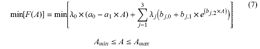
1. A method for determining the preload value of the screw based on thermal error and temperature rise weighting, wherein, firstly, under the different preload states of the screw, a thermal behavior test of the feed shaft under typical working conditions is carried out to obtain the maximum thermal error and the temperature rise at the key measuring points in each preload state; then, a mathematical model of the preload values of the screw and the maximum thermal error is established and, meanwhile, another mathematical model of the preload values of the screw and the temperature rise at the key measuring points is also established; finally, the optimal preload value of the screw is obtained by optimizing the weighting function of the maximum thermal error and the temperature rise at each measuring point as the objective function; the specific steps are as follows: the first step is the thermal behavior test of the feed shaft under typical working conditions; the first temperature sensor is located on the front bearing of the feed system, the second temperature sensor is located on the nut 6, the third temperature sensor is located on the rear bearing of the feed system, and the fourth temperature sensor is located on the bed near the screw; the motion trajectory of the machine tool is analyzed when machining the workpieces, and the motion information of the feed shaft is extracted, including the travel range, feed speed and running frequency; in the different preload states of the screw, the preload value of the screw is measured by the preload angle of the preload nut, and the thermal behavior test of the feed shaft is performed: in the initial thermal steady state, the full-range positioning error of the feed shaft is measured by a laser interferometer, and the temperature value of the first temperature sensor, the second temperature sensor, the third temperature sensor and the fourth temperature sensor are recorded; the feed shaft is heated under the motion information, and the positioning error of the whole journey is tested regularly, and the temperature of each measuring point is recorded; the heating machine process and the testing process are repeated until the screw reaches thermal balance; the second step is to calculate the maximum thermal error of the feed shaft and the temperature rise at the key measuring points; based on the thermal error and the temperature data collected in the first step, the maximum thermal error of the feed shaft is calculated according to equation (1) for each preload condition: E.sub.max_i=E.sub.i(M.sub.i,N)-E.sub.i(1,N) (1) where: E.sub.max_i is the maximum thermal error when the ith preload value is used; M.sub.i is the number of positioning error tests when the ith preload value is used; N is the number of points for the positioning error test; E.sub.i(M.sub.i,N) is the Nth point data of the M.sub.ith positioning error test when the ith preload value is used; E.sub.i(1,N) is the Nth point data of the first positioning error test when the ith preload value is used; the temperature rise of each measuring point under each preload value is calculated according to equation (2): .DELTA.T.sub.i,j=[T.sub.i,j(M.sub.i)-T.sub.i,j(1)]-[T.sub.i,4(M.sub.i)-T.- sub.i,4(1)] (2) where: .DELTA.T.sub.i,j is the temperature rise of the jth temperature sensor when the ith preload value is used; T.sub.i,j(M.sub.i) is the M.sub.ith measurement value of the jth temperature sensor when the ith preload value is used; T.sub.i,j(1) is the first measurement value of the jth temperature sensor when the ith preload value is used; T.sub.i,4(M.sub.i) is the M.sub.ith measurement value of the fourth temperature sensor (9) when the ith preload value is used, and T.sub.i,4(1) is the first measurement value of the fourth temperature sensor (9) when the ith preload value is used; the third step is to establish a mathematical model of the preload values of the screw and the maximum thermal error and another mathematical model of the preload values of the screw and the temperature rise at the key measuring points; the relationship between the preload value of the screw and the maximum thermal error of the feed shaft is as shown in equation (3): E.sub.max=a.sub.0-a.sub.1.times.A (3) where: E.sub.max is the maximum thermal error of the feed shaft, A is the preload value of the screw, that is, the locking angle of the preload nut (12), and a.sub.0 and a.sub.1 are coefficients; the mathematical model of the preload values of the screw and the temperature rise of the jth temperature sensor is shown in equation (4): .DELTA. T j = b j , 0 + b j , 1 .times. e ( b j , 2 .times. A ) ( 4 ) ##EQU00008## where: .DELTA.T.sub.j is the temperature rise of the jth temperature sensor, and b.sub.j,0, b.sub.j,1 and b.sub.j,2 are coefficients; according to the maximum thermal error and temperature rise data of the screw under the different preload values obtained in the second step, the coefficients a.sub.0, a.sub.1, b.sub.j,0, b.sub.j,1 and b.sub.j,2 in formula (3) and formula (4) are identified by the least squares method; the fourth step is to calculate the optimal preload value of the screw; the weighting functions of the maximum thermal error and temperature rise at key measuring points are shown in equation (5): F ( E max , .DELTA. T j ) = .lamda. 0 .times. E max + j = 1 3 .lamda. j .DELTA. T j ( 5 ) ##EQU00009## where: .lamda..sub.0 is the weight coefficient of the maximum thermal error of the feed shaft, and .lamda..sub.j is the weight coefficient of the temperature rise of the jth temperature sensor; rewriting equation (5) according to equations (3) and (4) gives: F ( A ) = .lamda. 0 .times. ( a 0 - a 1 .times. A ) + j = 1 3 .lamda. j ( b j , 0 + b j , 1 .times. e ( b j , 2 .times. A ) ) ( 6 ) ##EQU00010## Through automatic optimization based on equation (7), the optimal preload value of the screw can be obtained; min [ F ( A ) ] = min [ .lamda. 0 .times. ( a 0 - a 1 .times. A ) + j = 1 3 .lamda. j ( b j , 0 + b j , 1 .times. e ( b j , 2 .times. A ) ) ] ( 7 ) A min .ltoreq. A .ltoreq. A max ##EQU00011## where: A.sub.min and A.sub.max are the lower and upper limits of the preload value A of the screw respectively in the automatic optimization process.
Description
TECHNICAL FIELD
[0001] The invention belongs to the technical field of CNC machine tool assembly, and it is specifically a method for determining the preload value of the screw based on thermal error and temperature rise weighting.
BACKGROUND
[0002] During the operation of the feed shaft, the friction between the nut and the screw generates a large amount of heat, which is transferred to the screw and causes thermal expansion of the screw. If the feed shaft adopts a semi-closed-loop control mode, the thermal expansion of the screw will cause a change in the positioning accuracy of the shaft. This change corresponds to the thermal error of the feed shaft. This thermal error will ultimately affect the machining accuracy of the workpieces and the accuracy and consistency of the batches being processed.
[0003] A common method that is used in order to reduce the thermal error of the semi-closed-loop feed shaft is to preload the screw, that is, an axial preload force is applied to the screw by the preload nut, so that the screw undergoes the appropriate amount of axial pre-stretching. The larger the preload angle of the preload nut that is applied, the larger the pre-stretching amount of the screw. When the screw is heated, the internal stress generated by the pre-stretching of the screw will be first offset without elongation. When the internal stress is completely offset, the screw will extend as the result of the heating. This will effectively reduce the thermal error of the feed shaft.
[0004] The current method of reducing the thermal error of the feed shaft by preloading the screw has the following disadvantages: the preload value of the screw is generally determined based on experience and mainly takes the suppression effect on the thermal error into consideration, which makes it difficult to achieve the optimal effect. If the preload value of the screw is too small, the suppressing effect on the thermal error is insufficient; if the preload value of the screw is too large, although the suppressing effect on the thermal error is good, the temperature rise of both the front and rear bearings of the screw will be excessively large, which will accelerate bearing wear and shorten its service life. In the patent "EXPERIMENTAL OPTIMIZATION METHOD FOR BALL SCREW PRE-TIGHTENING FORCE OF CNC MACHINE TOOL FEED SYSTEM" (application no. 201610285987.5), Li et al. proposed an optimization method for the preload force of the screw with the positioning accuracy and dynamic characteristics of the feed shaft, but the influence of the preload force of the screw on the thermal error and the temperature rise of both the front and rear bearings was not considered. Therefore, the optimal preload force of the screw obtained by this method cannot meet the common requirements of suppressing the thermal error and providing control over the temperature rise.
SUMMARY OF THE INVENTION
[0005] A method for determining the preload value of the screw based on the thermal error and temperature rise weighting is proposed in this invention, aiming at the current situation where there is no method to determine the optimal preload value that comprehensively considers the thermal error and temperature rise. The optimal preload value of the screw is obtained by comprehensively considering the suppression of the thermal error of the feed shaft and the control over the temperature rise at the key measuring points.
The Technical Solution of the Present Invention
[0006] Based on the method for determining the preload value of the screw with thermal error and temperature rise weighting, firstly, under the different preload states of the screw, a thermal behavior test of the feed shaft under typical working conditions is carried out to obtain the maximum thermal error and the temperature rise at the key measuring points in each preload state. Then, a mathematical model of the preload values of the screw and the maximum thermal error is established and, meanwhile, another mathematical model of the preload values of the screw and the temperature rise at the key measuring points is also established. Finally, the optimal preload value of the screw is obtained by optimizing the weighting function of the maximum thermal error and the temperature rise at each measuring point as the objective function. The specific steps are as follows:
[0007] The first step is the thermal behavior test of the feed shaft under typical working conditions.
[0008] The first temperature sensor 3 is located on the front bearing 2 of the feed system, the second temperature sensor 7 is located on the nut 6, the third temperature sensor 10 is located on the rear bearing 11 of the feed system, and the fourth temperature sensor 9 is located on the bed 8 near the screw.
[0009] The motion trajectory of the machine tool is analyzed when machining the workpieces, and the motion information of the feed shaft is extracted, including the travel range, feed speed and running frequency.
[0010] In the different preload states of the screw, the preload value of the screw is measured by the preload angle of the preload nut 12, and the thermal behavior test of the feed shaft is performed: In the initial thermal steady state, the full-range positioning error of the feed shaft is measured by a laser interferometer, and the temperature value of the first temperature sensor 3, the second temperature sensor 7, the third temperature sensor 10 and the fourth temperature sensor 9 are recorded. The feed shaft is heated under the motion information, and the positioning error of the whole journey is tested regularly (about every 15 minutes), and the temperature of each measuring point is recorded. The heating engine process and the testing process are repeated until the screw reaches thermal balance.
[0011] The second step is to calculate the maximum thermal error of the feed shaft and the temperature rise at the key measuring points.
[0012] Based on the thermal error and the temperature data collected in the first step, the maximum thermal error of the feed shaft is calculated according to equation (1) for each preload condition:
E.sub.max_i=E.sub.i(M.sub.i,N)-E.sub.i(1,N) (1)
[0013] where: E.sub.max_i is the maximum thermal error when the ith preload value is used. M.sub.i is the number of positioning error tests when the ith preload value is used. N is the number of points for the positioning error test. E.sub.i(M.sub.i,N) is the Nth point data of the M.sub.ith positioning error test when the value is used. E.sub.i(1,N) is the Nth point data of the first positioning error test when the ith preload value is used;
[0014] The temperature rise of each measuring point under each preload value is calculated according to equation (2):
.DELTA.T.sub.i,j=[T.sub.i,j(M.sub.i)-T.sub.i,j(1)]-[T.sub.i,4(M.sub.i)-T- .sub.i,4(1)] (2)
where: .DELTA.T.sub.i,j is the temperature rise of the jth temperature sensor when the ith preload value is used. T.sub.i,j(M.sub.i) is the M.sub.ith measurement value of the jth temperature sensor when the ith preload value is used. T.sub.i,j(1) is the first measurement value of the jth temperature sensor when the ith preload value is used. T.sub.i,4(M.sub.i) is the M.sub.ith measurement value of the fourth temperature sensor 9 when the ith preload value is used, and T.sub.i,4(1) is the first measurement value of the fourth temperature sensor 9 when the ith preload value is used.
[0015] The third step is to establish a mathematical model of the preload values of the screw and the maximum thermal error and another mathematical model of the preload values of the screw and the temperature rise at the key measuring points.
[0016] The relationship between the preload value of the screw and the maximum thermal error of the feed shaft is as shown in equation (3):
E.sub.max=a.sub.0-a.sub.1.times.A (3)
where: E.sub.max is the maximum thermal error of the feed shaft, A is the preload value of the screw, that is, the locking angle of the preload nut 12, and a.sub.0 and a.sub.1 are coefficients.
[0017] The mathematical model of the preload values of the screw and the temperature rise of the jth temperature sensor is shown in equation (4):
.DELTA. T j = b j , 0 + b j , 1 .times. e ( b j , 2 .times. A ) ( 4 ) ##EQU00001##
where: .DELTA.T.sub.j is the temperature rise of the jth temperature sensor, and b.sub.j,0, b.sub.j,1 and b.sub.j,2 are coefficients.
[0018] According to the maximum thermal error and temperature rise data of the screw under the different preload values obtained in the second step, the coefficients a.sub.0, a.sub.1, b.sub.j,0, b.sub.j,1 and b.sub.j,2 in formula (3) and formula (4) are identified by the least squares method.
[0019] The fourth step is to calculate the optimal preload value of the screw.
[0020] The weighted functions of the maximum thermal error and temperature rise at key measuring points are shown in equation (5):
F ( E max , .DELTA. T j ) = .lamda. 0 .times. E max + j = 1 3 .lamda. j .DELTA. T j ( 5 ) ##EQU00002##
where: .lamda..sub.0 is the weight coefficient of the maximum thermal error of the feed shaft, and .lamda..sub.j is the weight coefficient of the temperature rise of the jth temperature sensor;
[0021] Rewriting equation (5) according to equations (3) and (4) gives:
F ( A ) = .lamda. 0 .times. ( a 0 - a 1 .times. A ) + j = 1 3 .lamda. j ( b j , 0 + b j , 1 .times. e ( b j , 2 .times. A ) ) ( 6 ) ##EQU00003##
[0022] Through automatic optimization based on equation (7), the optimal preload value of the screw can be obtained;
min [ F ( A ) ] = min [ .lamda. 0 .times. ( a 0 - a 1 .times. A ) + j = 1 3 .lamda. j ( b j , 0 + b j , 1 .times. e ( b j , 2 .times. A ) ) ] ( 7 ) A min .ltoreq. A .ltoreq. A max ##EQU00004##
where: A.sub.min and A.sub.max are the lower and upper limits of the preload value A of the screw respectively in the automatic optimization process.
[0023] The beneficial effect of the present invention is that the thermal error of the feed shaft and the temperature rise of the moving components are comprehensively considered, and the optimal preload value of the screw is obtained through the thermal behavior test of the feed shaft and the preload calculation under typical working conditions, thus solving the problem that the current experience-based method for determining the preload value of the screw is difficult to achieve the optimal effect. According to the method for determining the preload value of the screw, the invention can effectively reduce the thermal error of the feed shaft and control the temperature rise of the moving components such as bearings, thus improving the processing accuracy and stability of the machine tool, and ensuring the service life of the moving components such as bearings.
DRAWINGS
[0024] FIG. 1 shows a schematic diagram of the location of the temperature measuring points of the feed shaft.
[0025] FIG. 2 shows the effect of modeling the maximum thermal error.
[0026] FIG. 3(a) shows the effect of modeling the temperature rise of the first temperature sensor.
[0027] FIG. 3(b) shows the effect of modeling the temperature rise of the second temperature sensor.
[0028] FIG. 3(c) shows the effect of modeling the temperature rise of the third temperature sensor.
[0029] In the figures: 1 feed shaft motor; 2 front bearings of the screw; 3 the first temperature sensor; 4 screw; 5 work table; 6 nut; 7 the second temperature sensor; 8 bed; 9 the fourth temperature sensor; 10 the third temperature sensor; 11 rear bearings; 12 preload nuts.
DETAILED DESCRIPTION
[0030] In order to make the objects, technical solutions, and the advantages of the present invention clearer, the present invention is described in detail with reference to the accompanying drawings.
[0031] The embodiment of the present invention is described in detail, taking the X-axis of a vertical machining center as an example. The machining center has an X-axis travel range of 0.about.-500 mm and the maximum feed speed is 32000 mm/min.
[0032] The first step is the thermal behavior test of the feed shaft under typical working conditions.
[0033] The first temperature sensor 3 is located on the front bearing 2 of the feed system, the second temperature sensor 7 is located on the nut 6, the third temperature sensor 10 is located on the rear bearing 11 of the feed system, and the fourth temperature sensor 9 is located on the bed 8 near the screw.
[0034] The measured machining center is oriented towards the consumer electronics industry. The typical workpieces processed are aluminum casings for mobile phones and tablet computers. The typical working conditions are determined according to the processing process: the common travel range is -100.about.-400 mm; the common feed speed is 2000 mm/min; the average machining time of a single workpiece is 90 s, and the machining interval of the workpieces is 15 s.
[0035] The thermal behavior test of the feed shaft is carried out respectively under the conditions that the preload nuts have locking angles of 0.degree., 60.degree., 120.degree., 180.degree. and 270.degree.:
[0036] In the initial thermal steady state of the feed shaft, the full-range positioning error of the feed shaft is tested by a laser interferometer, and the temperature values from the first temperature sensor 3, the second temperature sensor 7, the third temperature sensor 10, and the fourth temperature sensor 9 are recorded. Then, the feed shaft is heated under typical motion information. The heating engine program is shown in Table 1.
TABLE-US-00001 TABLE 1 CNC program for heating engine AAA: G4F1 BBB: REPEAT BBBP = 14 G90 G1 X-400 F2000 G4F15 G4F1 goto AAA X-100 M30 Down to the second column Finished
[0037] The full-range positioning error is tested every 15 minutes during the movement, and the temperature values of the first temperature sensor 3, the second temperature sensor 7, the third temperature sensor 10, and the fourth temperature sensor 9 are recorded. The heating engine process is run for 2 hours, when the feed shaft reaches thermal balance, the test is stopped.
[0038] The second step is to calculate the maximum thermal error of the feed shaft and the temperature rise at the key measuring points.
[0039] Based on the thermal error and the temperature data collected in the first step, the maximum thermal error of the feed shaft in each preload condition is calculated according to equation (1):
E.sub.max_i=E.sub.i(M.sub.i,N)-E.sub.i(1,N) (1)
where: E.sub.max_i is the maximum thermal error when the ith preload value is used. M.sub.i is the number of positioning error tests when the ith preload value is used, and N is the number of points for the positioning error test. E.sub.i(M.sub.i,N) is the Nth point data of the M.sub.ith positioning error test when the ith preload value is used. E.sub.i(1,N) is the Nth point data of the first positioning error test when the ith preload value is used.
[0040] The temperature rise for each measuring point under each preload value is calculated according to equation (2):
.DELTA.T.sub.i,j=[T.sub.i,j(M.sub.i)-T.sub.i,j(1)]-[T.sub.i,4(M.sub.i)-T- .sub.i,4(1)] (2)
where: .DELTA.T.sub.i,j is the temperature rise of the jth temperature sensor when the ith preload value is used. T.sub.i,j(M.sub.i) is the M.sub.ith measurement value of the jth temperature sensor when the ith preload value is used. T.sub.i,j(1) is the first measurement value of the jth temperature sensor when the ith preload value is used. T.sub.i,4(M.sub.i) is the M.sub.ith measurement value of the fourth temperature sensor 9 when the ith preload value is used. T.sub.i,4(1) is the first measurement value of the fourth temperature sensor 9 when the ith preload value is used.
[0041] According to equation (1) and equation (2), the maximum thermal error and the temperature rise of each measuring point under each preload value of the screw are then calculated. The specific results are shown in Table 2.
TABLE-US-00002 TABLE 2 Summary of the Maximum Thermal Error and Temperature Rise Data Temperature Temperature Temperature rise of rise of rise of Maximum the first the second the third Preload thermal temperature temperature temperature value/.degree. error/.mu.m sensor/.degree. C. sensor/.degree. C. sensor/.degree. C. 0 29.6 3.24 2.89 2.76 60 27.2 3.35 2.97 2.98 120 20.6 3.47 3.11 3.36 180 13.5 4.01 2.94 3.97 270 8.8 5.23 3.05 4.98
[0042] The third step is to establish one mathematical model of the preload values of the screw and the maximum thermal error and another mathematical model of the preload values of the screw and the temperature rise at the key measuring points.
[0043] The relationship between the preload value of the screw and the maximum thermal error of the feed shaft is as shown in equation (3):
E.sub.max=a.sub.0-a.sub.1.times.A (3)
where: E.sub.max is the maximum thermal error of the feed shaft, A is the preload value of the screw (i.e., the locking angle of the preload nut 12), and a.sub.0 and a.sub.1 are coefficients.
[0044] The mathematical model of the preload values of the screw and the temperature rise of the jth temperature sensor is shown in equation (4):
.DELTA.T.sub.1=b.sub.j,0+b.sub.j,1.times.e.sup.(b.sup.j,2.sup..times.A) (4)
where: .DELTA.T.sub.j is the temperature rise of the jth temperature sensor, b.sub.j,0, b.sub.j,1 and b.sub.j,2 are coefficients.
[0045] According to the maximum thermal error and the temperature rise data, under the different preload values of the screw obtained in the second step, and based on the least squares method, the coefficients in the model can be obtained according to equation (3) and equation (4). The coefficients are as follows: a.sub.0=30.418, a.sub.1=0.083, b.sub.1,0=3.073, b.sub.1,1=0.15, b.sub.1,2=0.010, b.sub.2,0=0.718, b.sub.2,1=2.220, b.sub.2=0.0002, b.sub.3,0=1.814, b.sub.3,1=0.912 and b.sub.3=0.005. The effect of modeling the maximum thermal error is shown in FIG. 2, and the effect of modeling the temperature rise of the first to the third temperature sensors is shown in FIG. 3(a).about.FIG. 3(c).
[0046] The fourth step is to calculate the optimal preload value of the screw.
[0047] The weighting function of the maximum thermal error and the temperature rise at the key measuring points is shown in equation (5):
F ( E max , .DELTA. T j ) = .lamda. 0 .times. E max + j = 1 3 .lamda. j .DELTA. T j ( 5 ) ##EQU00005##
where: .lamda..sub.0 is the weight coefficient of the maximum thermal error of the feed shaft, and .lamda..sub.j is the weight coefficient of the temperature rise of the jth temperature sensor.
[0048] Rewriting equation (5) according to equations (3) and (4) gives:
F ( A ) = .lamda. 0 .times. ( a 0 - a 1 .times. A ) + j = 1 3 .lamda. j ( b j , 0 + b j , 1 .times. e ( b j , 2 .times. A ) ) ( 6 ) ##EQU00006##
[0049] Considering the suppression effect on the thermal error and the control over the temperature rise, the weight coefficients in the equation (6) are set as: .lamda..sub.0=0.15, .lamda..sub.1=0.8, .lamda..sub.2=0.1, and .lamda..sub.3=0.8.
[0050] Then automatic optimization is carried out based on equation (7):
min [ F ( A ) ] = min [ .lamda. 0 .times. ( a 0 - a 1 .times. A ) + j = 1 3 .lamda. j ( b j , 0 + b j , 1 .times. e ( b j , 2 .times. A ) ) ] ( 7 ) A min .ltoreq. A .ltoreq. A max ##EQU00007##
[0051] The optimal preload value of the X-axis screw of the vertical machining center can be obtained as 156.degree..
* * * * *
D00000
D00001
D00002


XML
uspto.report is an independent third-party trademark research tool that is not affiliated, endorsed, or sponsored by the United States Patent and Trademark Office (USPTO) or any other governmental organization. The information provided by uspto.report is based on publicly available data at the time of writing and is intended for informational purposes only.
While we strive to provide accurate and up-to-date information, we do not guarantee the accuracy, completeness, reliability, or suitability of the information displayed on this site. The use of this site is at your own risk. Any reliance you place on such information is therefore strictly at your own risk.
All official trademark data, including owner information, should be verified by visiting the official USPTO website at www.uspto.gov. This site is not intended to replace professional legal advice and should not be used as a substitute for consulting with a legal professional who is knowledgeable about trademark law.