Refrigerator Appliance With Direct-cooled In-door Chamber
Kind Code
U.S. patent application number 16/268573 was filed with the patent office on 2020-08-06 for refrigerator appliance with direct-cooled in-door chamber. The applicant listed for this patent is Haier US Appliance Solutions, Inc.. Invention is credited to John Keith Besore, Brian Michael Schork.
| Application Number | 20200248950 16/268573 |
| Document ID | 20200248950 / US20200248950 |
| Family ID | 1000003885828 |
| Filed Date | 2020-08-06 |
| Patent Application | download [pdf] |
| United States Patent Application | 20200248950 |
| Kind Code | A1 |
| Schork; Brian Michael ; et al. | August 6, 2020 |
REFRIGERATOR APPLIANCE WITH DIRECT-COOLED IN-DOOR CHAMBER
Abstract
A refrigerator appliance includes a cabinet that defines a chilled chamber. A door is rotatably mounted to the cabinet at a front portion of the chilled chamber. A food storage chamber is defined within the door. The refrigerator appliance also includes a sealed system configured for generating chilled air. The sealed system is in direct fluid communication with the in-door food storage chamber to provide the chilled directly to the in-door food storage chamber.
| Inventors: | Schork; Brian Michael; (Louisville, KY) ; Besore; John Keith; (Prospect, KY) | ||||||||||
| Applicant: |
|
||||||||||
|---|---|---|---|---|---|---|---|---|---|---|---|
| Family ID: | 1000003885828 | ||||||||||
| Appl. No.: | 16/268573 | ||||||||||
| Filed: | February 6, 2019 |
| Current U.S. Class: | 1/1 |
| Current CPC Class: | F25D 17/065 20130101; F25D 2317/062 20130101; F25D 23/02 20130101; F25D 2317/061 20130101 |
| International Class: | F25D 17/06 20060101 F25D017/06; F25D 23/02 20060101 F25D023/02 |
Claims
1. A refrigerator appliance defining a vertical direction, a lateral direction and a transverse direction, the vertical, lateral and transverse directions being mutually perpendicular, the refrigerator appliance comprising: a cabinet extending from a top to a bottom along the vertical direction, the cabinet also extending from a left side to a right side along the lateral direction, the cabinet defining a fresh food chamber, the fresh food chamber extending along the vertical direction between the top and the bottom of the cabinet, along the lateral direction between the left and right sides of the cabinet, and along the transverse direction between a front portion and a back portion, the front portion of the fresh food storage chamber defining an opening for receipt of food items; a door rotatably mounted to the cabinet at the front portion of the fresh food storage chamber such that the door rotates between a closed position where the door sealingly encloses at least a portion of the fresh food storage chamber and an open position to permit access to the fresh food chamber, the door comprising an outer casing comprising a thermally insulated wall that defines an in-door chamber within the outer casing, the door further comprising a front panel rotatably mounted to the outer casing of the door such that the front panel of the door permits access to the in-door chamber when the door is in the closed position; a sealed system configured for generating chilled air; and a duct directly fluidly connecting the sealed system with the in-door chamber to provide the chilled air directly from the sealed system to the in-door chamber.
2. The refrigerator appliance of claim 1, further comprising a variable speed blower fan in fluid communication with the sealed system to urge the chilled air from the sealed system into the duct and directly to the in-door chamber from an evaporator of the sealed system.
3. The refrigerator appliance of claim 1, wherein the cabinet also defines a freezer chamber extending along the vertical direction between the top and bottom of the cabinet and spaced apart from the fresh food chamber along the vertical direction, wherein the duct is a first duct, and further comprising a second duct extending from the in-door chamber to the freezer chamber.
4. The refrigerator appliance of claim 3, further comprising a valve in the first duct, the valve configured to divert a portion of the chilled air to a third duct, the third duct extending from the valve to the freezer chamber.
5. The refrigerator appliance of claim 4, further comprising a variable speed blower fan in fluid communication with the sealed system to urge the chilled air from the sealed system into the first duct.
6. The refrigerator appliance of claim 3, further comprising a variable speed blower fan in fluid communication with the sealed system to urge a first portion of the chilled air from the sealed system into the first duct and an axial fan in fluid communication with the sealed system to urge a second portion of the chilled air from the sealed system directly into the freezer chamber.
7. The refrigerator appliance of claim 6, further comprising a check valve in the second duct, the check valve oriented within the second duct such that air flow from the freezer chamber to the in-door chamber through the second duct is obstructed by the check valve.
8. The refrigerator appliance of claim 1, wherein the cabinet comprises a plurality of thermally insulated walls, and the duct extends from the sealed system to the in-door chamber through the thermal insulation of at least one of the plurality of thermally insulated walls.
9. The refrigerator appliance of claim 1, wherein the door is a first fresh food chamber door, further comprising a second fresh food chamber door mirrored with the first fresh food chamber door whereby the first fresh food chamber door and the second fresh food chamber door cooperatively sealingly enclose the fresh food chamber when the first fresh food door is in the closed position and the second fresh food door is in a closed position, the second fresh food door comprising a second outer casing and a second thermally insulated wall defining a fresh food storage chamber within the second outer casing.
10. A refrigerator appliance, the refrigerator appliance comprising: a cabinet defining a chilled chamber, the chilled chamber comprising a front portion and an opening for receipt of food items defined at the front portion; a door rotatably mounted to the cabinet at the front portion of the chilled chamber such that the door rotates between a closed position where the door sealingly encloses at least a portion of the chilled chamber and an open position to permit access to the chilled chamber, the door comprising an outer casing comprising a thermally insulated wall that defines an in-door chamber within the outer casing, the door further comprising a front panel rotatably mounted to the outer casing of the door such that the front panel of the door permits access to the in-door chamber when the door is in the closed position; a sealed system configured for generating chilled air; and a duct directly fluidly connecting the sealed system with the in-door chamber to provide the chilled air directly from the sealed system to the in-door chamber.
11. The refrigerator appliance of claim 10, further comprising a variable speed blower fan in fluid communication with the sealed system to urge the chilled air from the sealed system into the duct and directly to the in-door chamber from an evaporator of the sealed system.
12. The refrigerator appliance of claim 10, wherein the cabinet also defines a freezer chamber positioned below and spaced apart from the fresh food chamber, wherein the duct is a first duct, and further comprising a second duct extending from the in-door chamber to the freezer chamber.
13. The refrigerator appliance of claim 12, further comprising a valve in the first duct, the valve configured to divert a portion of the chilled air to a third duct, the third duct extending from the valve to the freezer chamber.
14. The refrigerator appliance of claim 13, further comprising a variable speed blower fan in fluid communication with the sealed system to urge the chilled air from the sealed system into the first duct.
15. The refrigerator appliance of claim 14, further comprising a variable speed blower fan in fluid communication with the sealed system to urge a first portion of the chilled air from the sealed system into the first duct and an axial fan in fluid communication with the sealed system to urge a second portion of the chilled air from the sealed system directly into the freezer chamber.
16. The refrigerator appliance of claim 15, further comprising a check valve in the second duct, the check valve oriented within the second duct such that air flow from the freezer chamber to the in-door chamber through the second duct is obstructed by the check valve.
17. The refrigerator appliance of claim 10, wherein the cabinet comprises a plurality of thermally insulated walls, and the duct extends from the sealed system to the in-door chamber through the thermal insulation of at least one of the plurality of thermally insulated walls.
18. The refrigerator appliance of claim 10, wherein the door is a first fresh food chamber door, further comprising a second fresh food chamber door mirrored with the first fresh food chamber door whereby the first fresh food chamber door and the second fresh food chamber door cooperatively sealingly enclose the fresh food chamber when the first fresh food door is in the closed position and the second fresh food door is in a closed position, the second fresh food door comprising a second outer casing and a second thermally insulated wall defining a fresh food storage chamber within the second outer casing.
Description
FIELD OF THE INVENTION
[0001] The present disclosure relates generally to refrigerator appliances. In particular, the present disclosure relates to refrigerator appliances having a door-in-door compartment or chamber which is directly cooled by a sealed cooling system of the refrigerator appliance.
BACKGROUND OF THE INVENTION
[0002] Refrigerator appliances generally include a cabinet that defines chilled chambers for receipt of food items for storage. One or more insulated, sealing doors are provided for selectively enclosing the chilled food storage chambers. Consumers generally prefer chilled chambers that facilitate visibility and accessibility of food items stored therein.
[0003] In certain refrigerator appliances, commonly referred to as side-by-side style refrigerator appliance, the fresh food chamber is positioned next to the freezer chamber within the cabinet. Such a configuration can permit easy access to food items stored on doors of the refrigerator appliances. However, the cabinet can be deep and narrow such that accessing food items at a back of the fresh food chamber and/or freezer chamber is difficult.
[0004] In other refrigerator appliances, the freezer chamber is positioned either above or below the fresh food chamber in the cabinet, which are commonly referred to as top mount or bottom mount refrigerator appliances. Such a configuration can provide a relatively wide fresh food chamber and/or freezer chamber, e.g., as compared to the side-by-side configuration. However, the depth of the fresh food chamber and the freezer chamber can make accessing food items at a back of the refrigerator appliance difficult.
[0005] Accordingly, a refrigerator appliance with features for assisting with accessing food items stored therein would be useful.
BRIEF DESCRIPTION OF THE INVENTION
[0006] Aspects and advantages of the invention will be set forth in part in the following description, or may be apparent from the description, or may be learned through practice of the invention.
[0007] In an exemplary embodiment, a refrigerator appliance is provided. The refrigerator appliance defines a vertical direction, a lateral direction and a transverse direction. The vertical, lateral and transverse directions are mutually perpendicular. The refrigerator appliance includes a cabinet extending from a top to a bottom along the vertical direction. The cabinet also extends from a left side to a right side along the lateral direction. The cabinet defines a fresh food chamber. The fresh food chamber extends along the vertical direction between the top and bottom of the cabinet, along the lateral direction between the left side and the right side of the cabinet, and along the transverse direction between a front portion and a back portion. The front portion of the fresh food storage chamber defines an opening for receipt of food items. A door is rotatably mounted to the cabinet at the front portion of the fresh food storage chamber such that the door rotates between a closed position where the door sealingly encloses at least a portion of the fresh food storage chamber and an open position to permit access to the fresh food chamber. The door includes an outer casing comprising a thermally insulated wall that defines an in-door chamber within the outer casing and a front panel rotatably mounted to the outer casing of the door such that the front panel of the door permits access to the in-door chamber when the door is in the closed position. The refrigerator appliance also includes a sealed system configured for generating chilled air and a duct directly fluidly connecting the sealed system with the in-door chamber to provide the chilled air directly from the sealed system to the in-door chamber
[0008] In another exemplary embodiment, a refrigerator appliance is provided. The refrigerator appliance includes a cabinet that defines a chilled chamber. The chilled chamber includes a front portion and an opening for receipt of food items. A door is rotatably mounted to the cabinet at the front portion of the chilled chamber such that the door rotates between a closed position where the door sealingly encloses at least a portion of the chilled chamber and an open position to permit access to the chilled chamber. The door includes an outer casing comprising a thermally insulated wall that defines an in-door chamber within the outer casing and a front panel rotatably mounted to the outer casing of the door such that the front panel of the door permits access to the in-door chamber when the door is in the closed position. The refrigerator appliance also includes a sealed system configured for generating chilled air and a duct directly fluidly connecting the sealed system with the in-door chamber to provide the chilled air directly from the sealed system to the in-door chamber.
[0009] These and other features, aspects and advantages of the present invention will become better understood with reference to the following description and appended claims. The accompanying drawings, which are incorporated in and constitute a part of this specification, illustrate embodiments of the invention and, together with the description, serve to explain the principles of the invention.
BRIEF DESCRIPTION OF THE DRAWINGS
[0010] A full and enabling disclosure of the present invention, including the best mode thereof, directed to one of ordinary skill in the art, is set forth in the specification, which makes reference to the appended figures.
[0011] FIG. 1 provides a perspective view of an exemplary refrigerator appliance according to one or more embodiments of the present subject matter with front panels of the doors in an open position while the doors are each in a closed position.
[0012] FIG. 2 provides a perspective view of the refrigerator appliance of FIG. 1 with a first fresh food chamber door and a second fresh food chamber door both in an open position.
[0013] FIG. 3 provides a schematic illustration of an example sealed cooling system as may be used with one or more embodiments of the present subject matter.
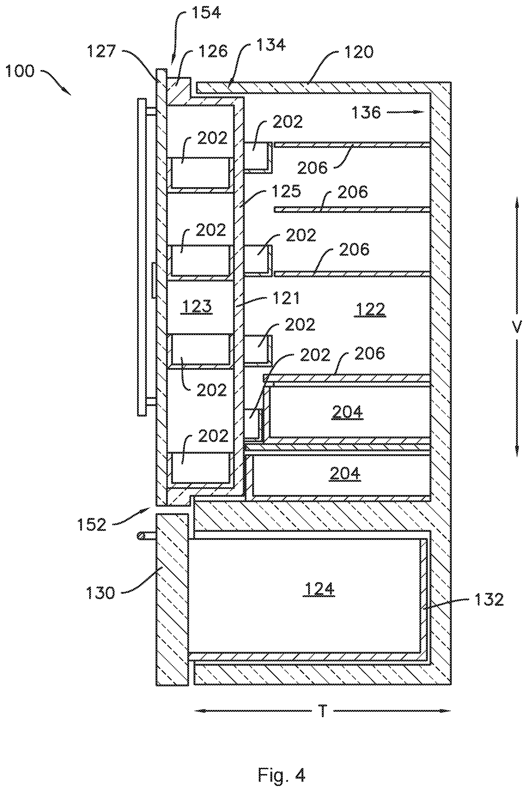
[0014] FIG. 4 provides a side section view of the exemplary refrigerator appliance of FIGS. 1 and 2 taken through the right-hand door.
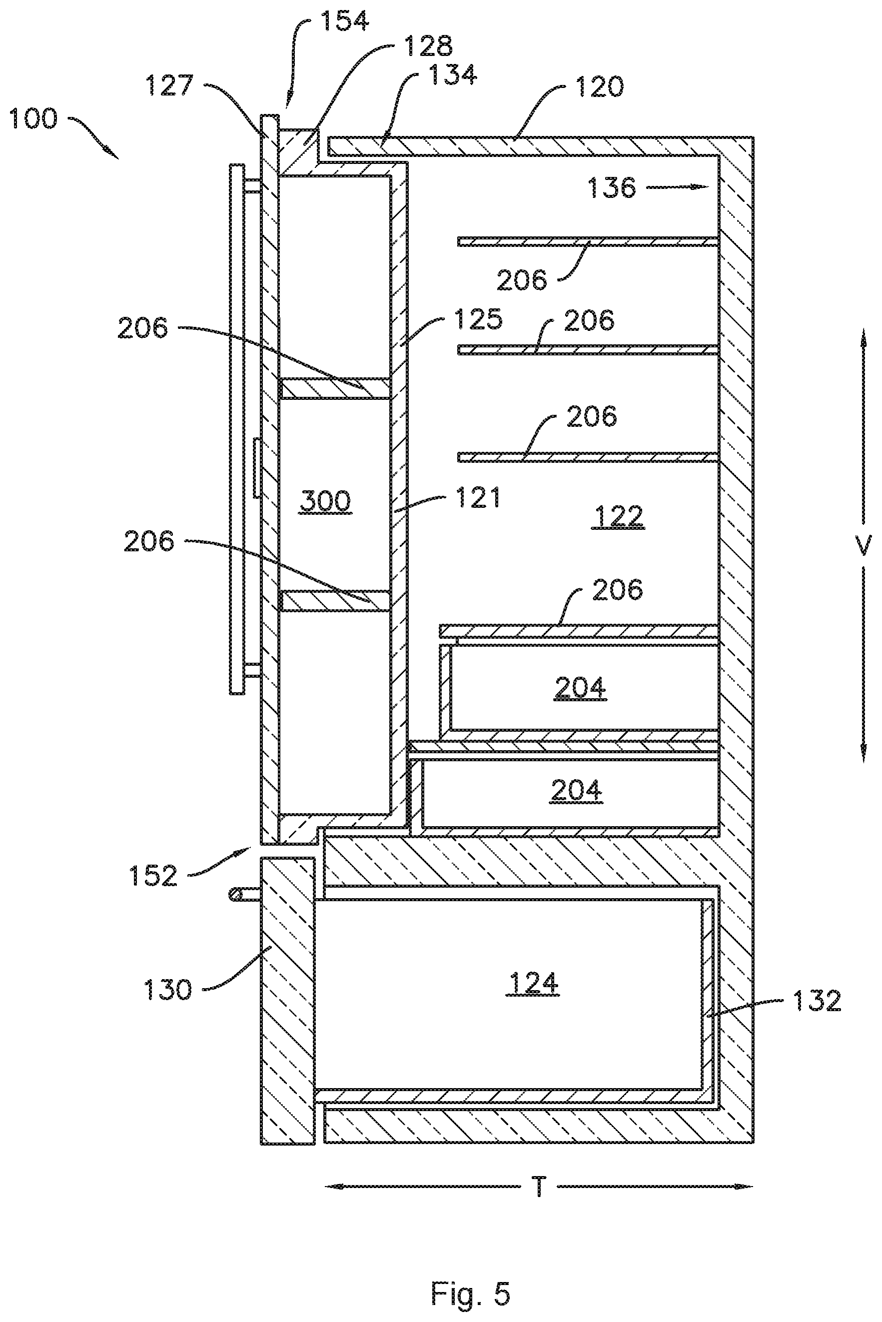
[0015] FIG. 5 provides a side section view of the exemplary refrigerator appliance of FIGS. 1 and 2 taken through the left-hand door.
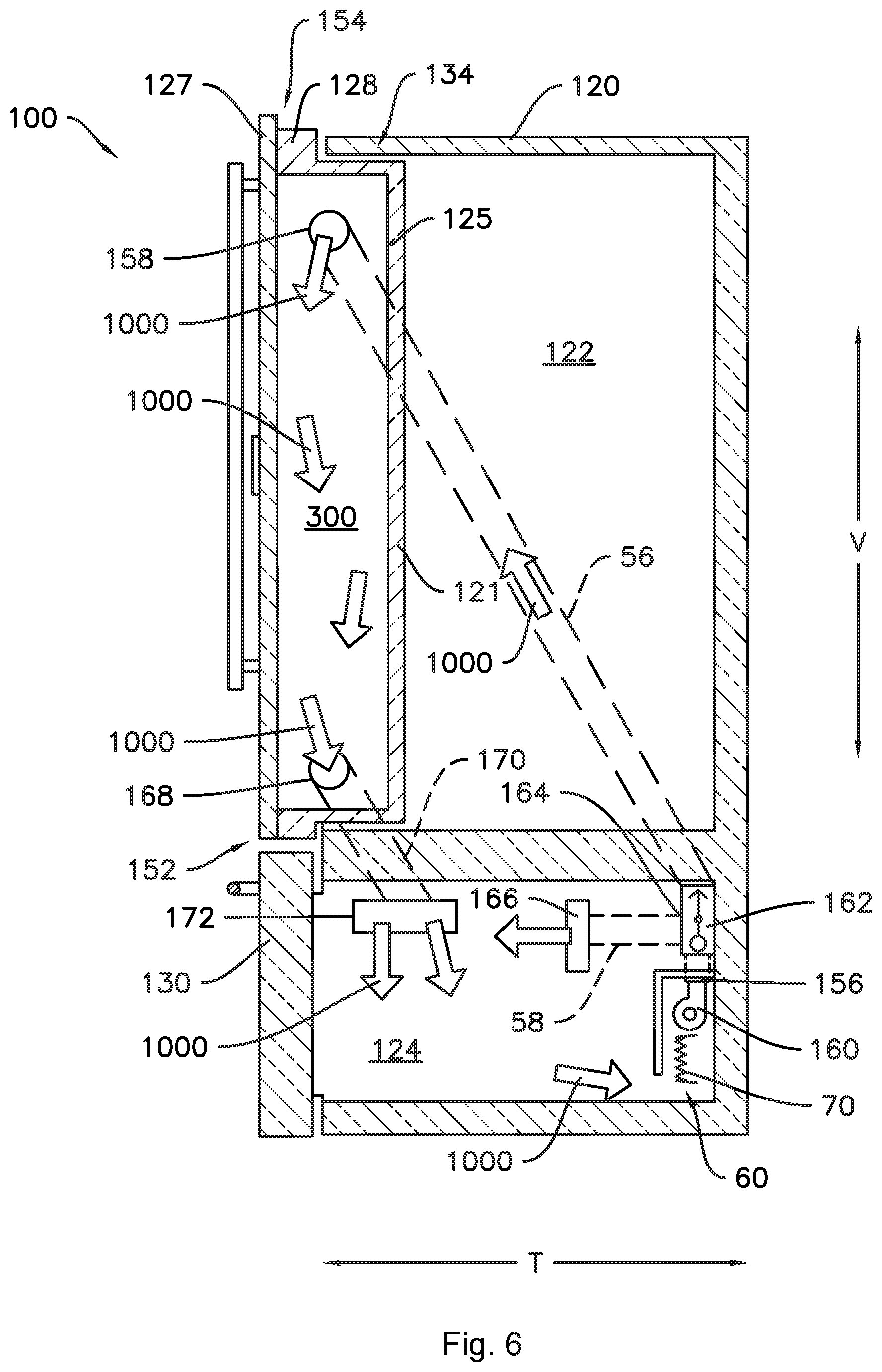
[0016] FIG. 6 provides a schematic view of a chilled air supply for an in-door chamber of a refrigerator appliance according to one or more embodiments of the present subject matter.
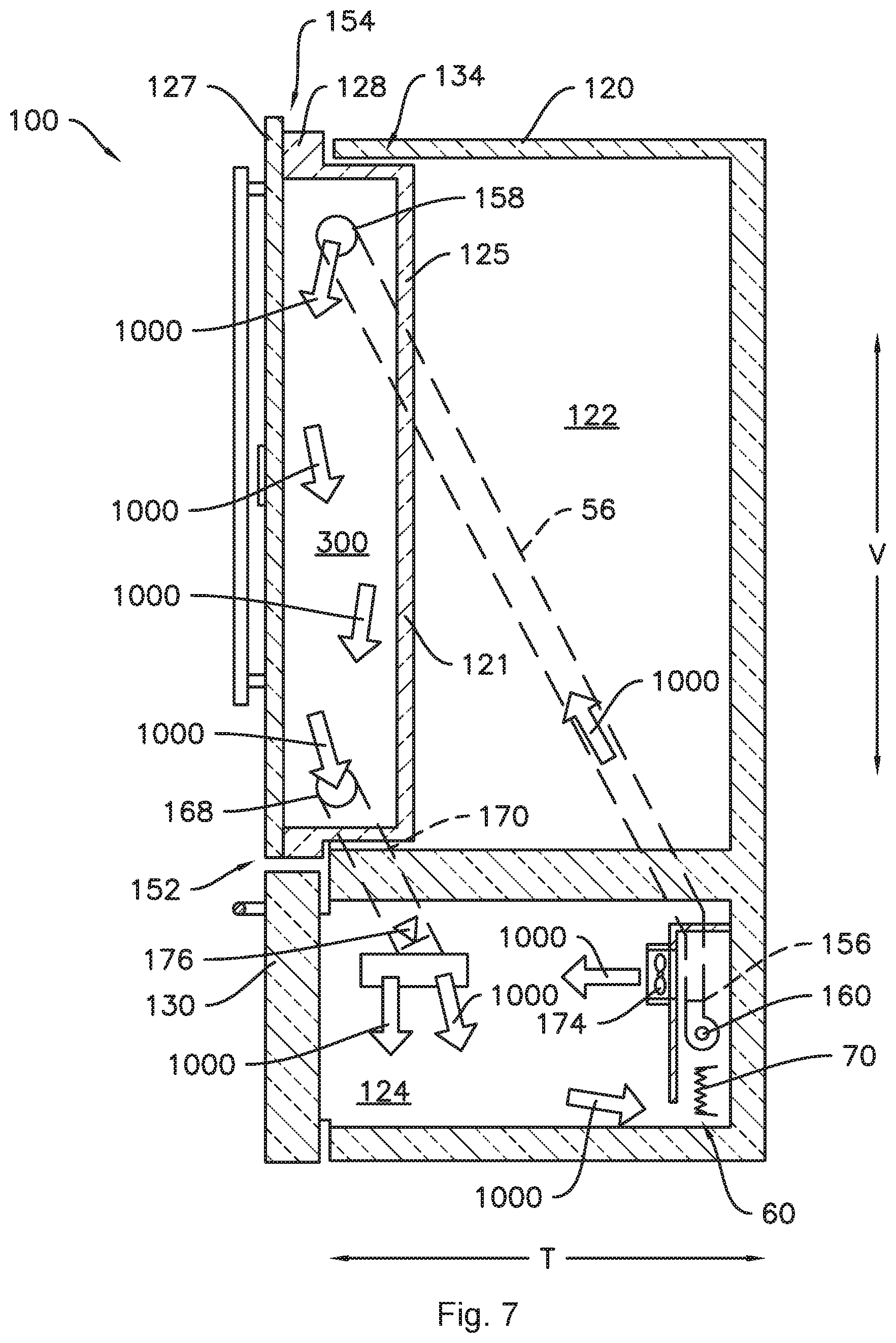
[0017] FIG. 7 provides a schematic view of a chilled air supply for an in-door chamber of a refrigerator appliance according to one or more additional embodiments of the present subject matter.
DETAILED DESCRIPTION
[0018] Reference now will be made in detail to embodiments of the invention, one or more examples of which are illustrated in the drawings. Each example is provided by way of explanation of the invention, not limitation of the invention. In fact, it will be apparent to those skilled in the art that various modifications and variations can be made in the present invention without departing from the scope or spirit of the invention. For instance, features illustrated or described as part of one embodiment can be used with another embodiment to yield a still further embodiment. Thus, it is intended that the present invention covers such modifications and variations as come within the scope of the appended claims and their equivalents.
[0019] As used herein, the terms "first," "second," and "third" may be used interchangeably to distinguish one component from another and are not intended to signify location or importance of the individual components. Terms such as "inner" and "outer" refer to relative directions with respect to the interior and exterior of the refrigerator appliance, and in particular the food storage chamber(s) defined therein. For example, "inner" or "inward" refers to the direction towards the interior of the refrigerator appliance. Terms such as "left," "right," "front," "back," "top," or "bottom" are used with reference to the perspective of a user accessing the refrigerator appliance. For example, a user stands in front of the refrigerator to open the doors and reaches into the food storage chamber(s) to access items therein.
[0020] As used herein, terms of approximation such as "generally," "about," or "approximately" include values within ten percent greater or less than the stated value. When used in the context of an angle or direction, such terms include within ten degrees greater or less than the stated angle or direction, e.g., "generally vertical" includes forming an angle of up to ten degrees either clockwise or counterclockwise with the vertical direction V.
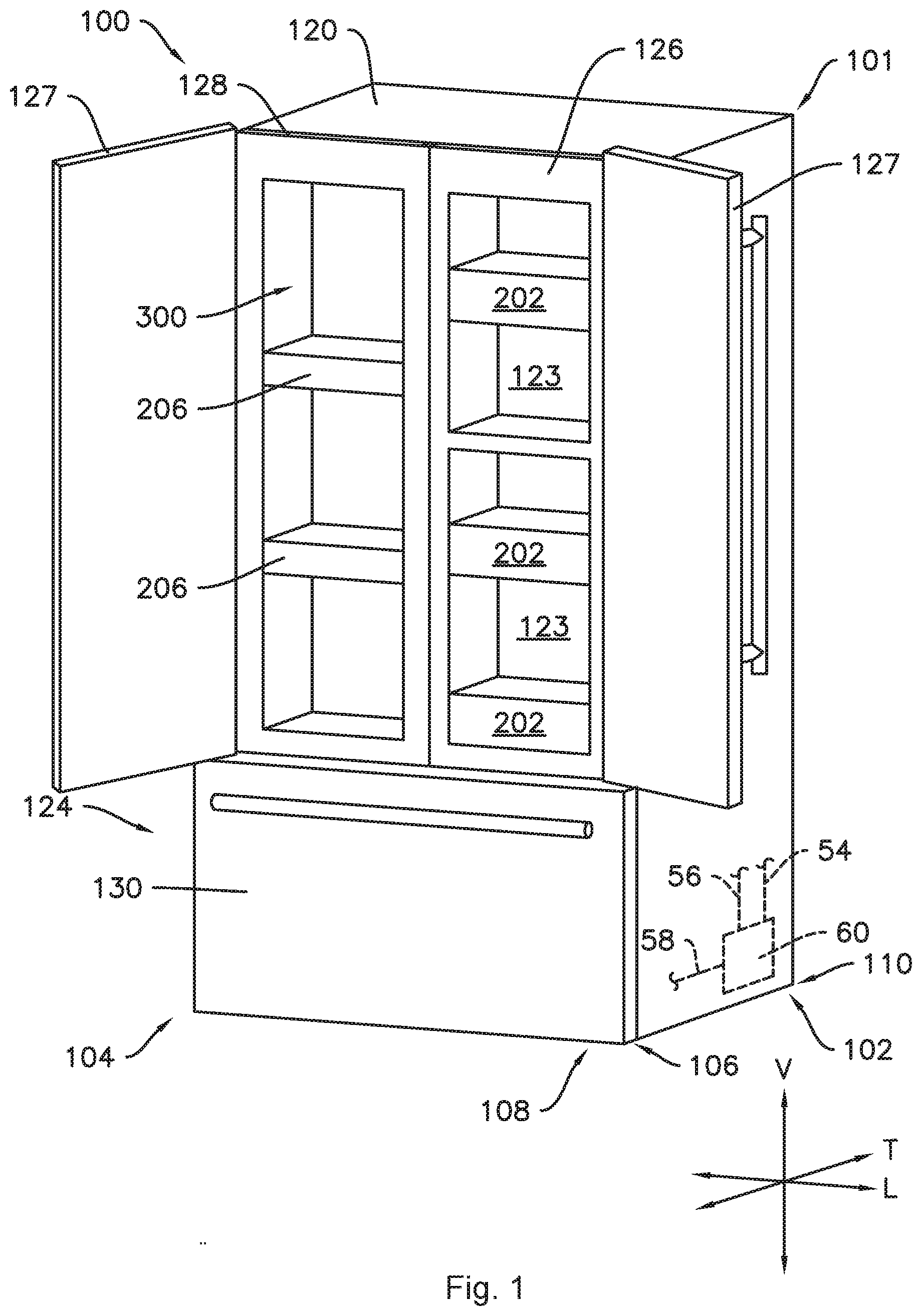
[0021] FIGS. 1 and 2 provide perspective views of an exemplary refrigerator appliance 100 according to one or more embodiments of the present subject matter. Refrigerator appliance 100 defines a vertical direction V, a lateral direction L, and a transverse direction T, each mutually perpendicular to one another. As may be seen in, e.g., FIG. 1, refrigerator appliance 100 includes a cabinet or housing 120 that extends between a top 101 and a bottom 102 along a vertical direction V, between a left side 104 and a right side 106 along the lateral direction L, and between a front 108 and a rear 110 along the transverse direction T. Cabinet 120 defines chilled chambers for receipt of food items for storage. As used herein, a chamber may be "chilled" in that the chamber is operable at temperatures below room temperature, e.g., less than about seventy-five degrees Fahrenheit (75.degree. F.). In the exemplary embodiment, cabinet 120 also defines a mechanical compartment at or near the bottom 102 of the cabinet 120 for receipt of a sealed cooling system 60. One or more conduits or ducts, e.g., ducts 54, 56, and 58 as illustrated for example in FIG. 1 may extend between the sealed cooling system 60 and the chilled chambers to provide fluid communication therebetween, e.g., to provide chilled air from the sealed cooling system to one or more of the chilled chambers, whereby the chilled chamber(s) may be operable at temperatures below room temperature.
[0022] In particular, cabinet 120 defines a fresh food chamber 122 (FIG. 2) and a freezer chamber 124 spaced apart from the fresh food chamber 122 along the vertical direction V. For example, in the illustrated embodiment of FIGS. 1 and 2, fresh food chamber 122 is positioned at or adjacent top 101 of cabinet 120 and freezer chamber 124 is arranged at or adjacent bottom 102 of cabinet 120. As such, refrigerator appliance 100 is generally referred to as a bottom mount refrigerator. It is recognized, however, that the benefits of the present disclosure may apply to other types and styles of refrigerator appliances such as, e.g., a top mount refrigerator appliance, or a side-by-side style refrigerator appliance. Consequently, the description set forth herein is for illustrative purposes only and is not intended to be limiting in any aspect to any particular refrigerator chamber configuration.
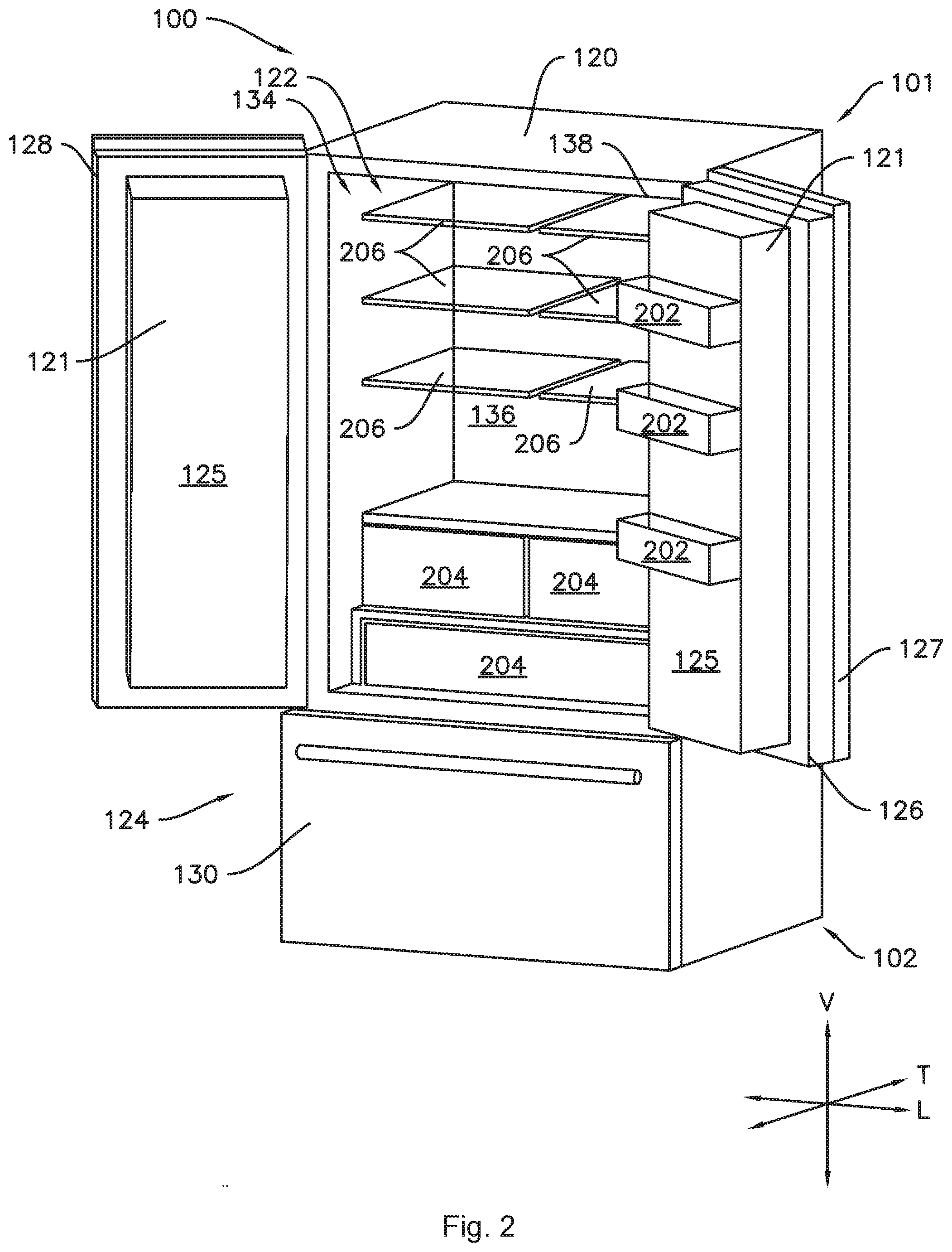
[0023] As may be seen in FIG. 2, the fresh food chamber 122 extends along the vertical direction V between the top 101 and the bottom 102 of the cabinet 120 and along the lateral direction L between the left side 104 and the right side 106 of the cabinet 120. For example, the fresh food chamber 122 may extend along the vertical direction V from the top 101 to the bottom 102 of the cabinet 120 (such as in a side-by-side configuration), or may extend from one of the top 101 or the bottom 102 to the freezer chamber 124 (such as in a top or bottom mount configuration), for example, in the illustrated bottom-mount embodiment, the fresh food chamber 122 extends along the vertical direction V from the top 101 of the cabinet 120 to the freezer chamber 124. The fresh food chamber 122 also extends along the transverse direction T from a front portion 134 to a back portion 136. The front portion 134 of the fresh food storage chamber 122 defines an opening 138 for receipt of food items.
[0024] Refrigerator doors 126 and 128 are rotatably mounted, e.g., hinged, to an edge of cabinet 120 for selectively accessing fresh food chamber 122. Since refrigerator doors 126 and 128 correspond to the fresh food chamber 122, the refrigerator doors 126 and 128 may also be referred to as fresh food chamber doors. Refrigerator doors 126 and 128 may be mounted to the cabinet 120 at or near the front portion 134 of the fresh food storage chamber 122 such that the doors 126 and 128 rotate between a closed position (FIG. 1) where the doors 126 and 128 cooperatively sealingly enclose the fresh food storage chamber 122 and an open position (FIG. 2) to permit access to the fresh food chamber 122. The doors 126 and 128 may be generally mirrored, e.g., the overall shape and size of each door 126, 128 may be the same as the other door 126, 128, with possible internal variations. In addition, a freezer door 130 is arranged below refrigerator doors 126 and 128 for selectively accessing freezer chamber 124. Freezer door 130 is coupled to a freezer drawer 132 (FIGS. 4 and 5) slidably mounted within freezer chamber 124. Refrigerator doors 126, 128 and freezer door 130 are shown in the closed configuration in FIG. 1.
[0025] As shown for example in FIGS. 1 and 2, various storage components are mounted within the chilled chambers to facilitate storage of food items therein as will be understood by those skilled in the art. In particular, the storage components may include various combinations of bins 202, drawers 204, and shelves 206 mounted within one or more of the chilled chambers. Bins 202, drawers 204, and shelves 206 are configured for receipt of food items (e.g., beverages and/or solid food items) and may assist with organizing such food items.
[0026] In addition to the fresh food chamber 122 and the freezer chamber 124, one or more chilled chambers may be defined in one or both of the doors 126 and 128. For example, one or both of the refrigerator doors, e.g., both right door 126 and left door 128 as in the illustrated example, may include an outer casing 121 (FIG. 2) comprising a thermally insulated wall 125 (FIG. 2) that defines one or more chilled chambers therein. For example, the right door 126 may include one or more fresh food storage chambers 123 (FIGS. 1 and 4) and the left door 128 may include at least one chilled chamber 300. In some embodiments, the chamber 300 in the door 128 may be, e.g., a first freezer chamber 300. The freezer chamber 300 may be referred to as an in-door freezer chamber because the chamber 300 may be provided within one or both of the doors 126 and 128, e.g., left door 128 in the illustrated example, such that the in-door freezer chamber 300 may be accessible without opening the respective door. As shown, each door 126 and 128 may include a front panel 127 rotatably mounted to the outer casing 121 of each door 126 and 128 such that the front panel 127 permits access to the chilled chamber(s) within the respective door, e.g., the fresh food storage chambers 123 in right door 126 and the chamber 300 in left door 128, when the door 126 or 128 is in the closed position, as shown for example in FIG. 1. In other embodiments, the chamber 300 may be provided in either one of the right door 126 or the left door 128, separately or in combination with another in-door chamber, e.g., the in-door chambers 123, in the other of the right door 126 or the left door 128.
[0027] In various embodiments, the fresh food storage chambers 122 and 123 may be selectively operable within a first temperature range and the freezer chamber 300 may be selectively operable within a second temperature range including lower temperatures than the first temperature range. For example, the chamber 300 may be an in-door freezer chamber in that the chamber 300 is operable at a temperature lower than the temperature of the fresh food storage chambers 122 or 123, including temperatures at or below the freezing point of water. Additionally, where the in-door freezer chamber 300 is directly fluidly connected to the sealed cooling system 60, the in-door freezer chamber 300 may be operable independently of the freezer chamber 124, including at temperatures lower than a temperature of the freezer chamber 124.
[0028] For example, the first temperature range of the fresh food chamber 122 may be between approximately thirty-three degrees Fahrenheit (33.degree. F.) and approximately forty (40.degree. F.) degrees Fahrenheit, such as between approximately thirty-five degrees Fahrenheit (35.degree. F.) and approximately thirty-eight degrees Fahrenheit (38.degree. F.). Also by way of example, the second temperature range may include temperatures less than thirty-two degrees Fahrenheit (32.degree. F.), such as about ten degrees Fahrenheit (10.degree. F.), such as about zero degrees Fahrenheit (0.degree. F.), and temperatures greater than forty degrees Fahrenheit (40.degree. F.), such as about forty-five degrees Fahrenheit (45.degree. F.) or higher, such as about sixty degrees Fahrenheit (60.degree. F.) or higher, such as about seventy degrees Fahrenheit (70.degree. F.). Still further, it should be understood that fresh food storage chambers 122 and 123 and freezer chamber 300 may be selectively operable at any number of various temperatures and/or temperature ranges as desired or required per application. For example, the in-door chamber 300 may also or instead be a flexible chamber or a fresh food chamber.
[0029] The sealed system 60 may be in fluid communication with the various chilled chambers to provide the chilled air to the chambers separately or in various combinations. In particular, the sealed system 60 may be directly in fluid communication with the in-door chamber 300. For example, a first duct 54 may extend between and provide fluid communication from the sealed system 60 to one or both of the fresh food storage chambers 122 and 123, a second duct 56 may extend between the sealed system 60 and the in-door chamber 300 to provide direct fluid communication from the sealed system 60 to the in-door chamber 300, and a third duct 58 may extend between and provide fluid communication from the sealed system 60 to the freezer chamber 124.
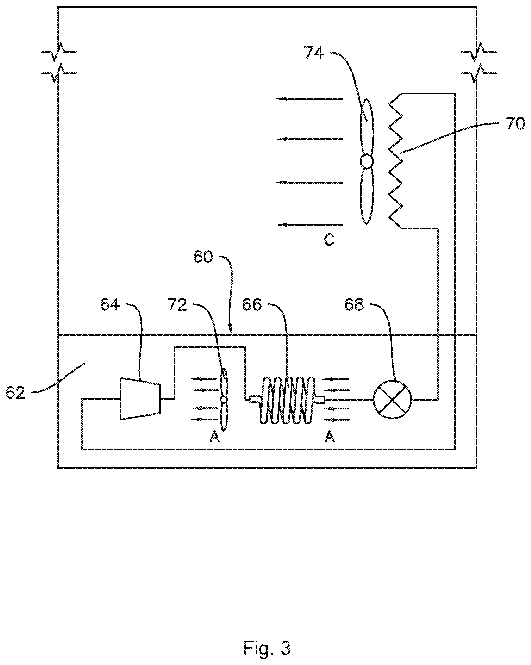
[0030] FIG. 3 provides a schematic view of the refrigerator appliance 100, in particular the sealed cooling system 60 thereof. As illustrated in FIG. 3, refrigerator appliance 100 includes a machinery compartment 62 that at least partially contains components for executing a known vapor compression cycle for cooling air. The components include a compressor 64, a heat exchanger or condenser 66, an expansion device 68, and an evaporator 70 connected in series and charged with a refrigerant. Evaporator 70 is also a type of heat exchanger which transfers heat from air passing over the evaporator to a refrigerant flowing through evaporator 70 thereby causing the refrigerant to vaporize. As such, cooled air C is produced and configured to refrigerate chambers 122, 123, 124, and 300 of refrigerator appliance 100. The cooled air C may be directed to the food storage chambers 122, 123, 124, and 300 by a fan 74.
[0031] From evaporator 70, vaporized refrigerant flows to compressor 64, which operates to increase the pressure of the refrigerant. This compression of the refrigerant raises its temperature, which is lowered by passing the gaseous refrigerant through condenser 66 where heat exchange with ambient air takes place so as to cool the refrigerant. A fan 72 is used to pull air across condenser 66, as illustrated by arrows A, so as to provide forced convection for a more rapid and efficient heat exchange between the refrigerant and the ambient air.
[0032] Expansion device 68 further reduces the pressure of refrigerant leaving condenser 66 before being fed as a liquid to evaporator 70. Collectively, the vapor compression cycle components in a refrigeration circuit, associated fans, and associated compartments are sometimes referred to as a sealed refrigeration system operable to force cold air through refrigeration chambers 122, 123, 124, and 300. The refrigeration system 60 depicted in FIG. 3 is provided by way of example only. It is within the scope of the present invention for other configurations of the refrigeration system to be used as well. For example, fan 74 may be repositioned so as to push air across evaporator 70, dual evaporators may be used with one or more fans, and numerous other configurations may be applied as well.
[0033] As may be seen in FIG. 4, the in-door fresh food storage chamber 123 and the door 126 may be generally coextensive. For example, as seen in FIG. 6, the chamber 123 and the door 126 may be generally coextensive along the vertical direction V, e.g. a vertical height of the in-door chamber 123 may be about the same (excepting the thickness of the thermally insulated walls defining the chamber 123) as a vertical height of the door 126. Referring back to FIG. 4, the in-door fresh food storage chamber 123 may extend along the vertical direction V from a bottom 152 of the door 126 to a top 154 of the door 126. The in-door fresh food storage chamber 123 and the door 126 may also be generally coextensive along a direction perpendicular to the vertical direction V, e.g., at least one of the lateral direction L and the transverse direction T, e.g., depending on the orientation of the door 126, e.g. whether the door 126 is in the closed position or the open position. For example, the door 126 may extend between a left side and a right side, e.g., along the lateral direction L when the door 126 is in the closed position, as illustrated in FIG. 1. In such embodiments, the flexible chamber 123 may extend from the left side of the door 126 to the right side of the door 126 such that the flexible chamber 123 is generally coextensive with the door 126 along a direction perpendicular to the vertical direction V, e.g., the lateral direction L.
[0034] FIG. 5 provides a section view taken through second fresh food chamber door 128, including food storage chamber 300 (which, as noted above may be but is not necessarily a freezer chamber) defined within the door 128. The in-door chamber 300 may be generally coextensive with the door 128, similarly to the chamber 123 and door 126 described above. In the illustrated example embodiment of FIG. 5, the in-door chamber 300 includes a plurality of shelves 206 therein. In other embodiments, various additional storage components may be mounted within the freezer chamber 300, e.g., various combinations of bins 202 and/or drawers 204, as well as or instead of shelves 206.
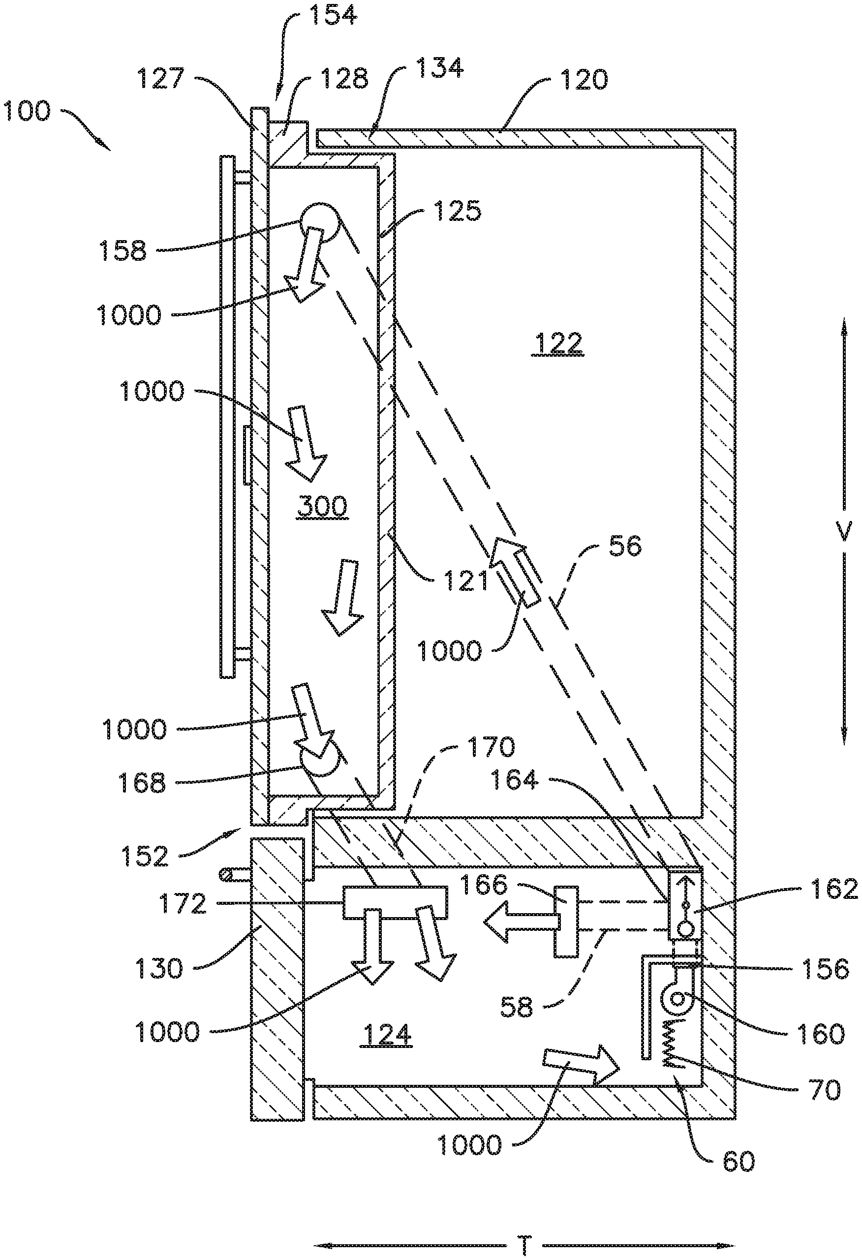
[0035] FIG. 6 provides a schematic view of a chilled air supply for the in-door chamber 300 according to one example embodiment of the present disclosure. As shown in FIG. 6, the chilled air supply includes a direct fluid connection from the sealed system 60, e.g., the evaporator 70 thereof, to the in-door chamber 300 via duct 56. For example, chilled air from the sealed system 60 may travel to the in-door chamber 300 without passing through the freezer chamber 124 due to the direct connection from the sealed system 60 to the in-door chamber 300. In some embodiments, e.g., as illustrated in FIG. 6, a blower fan 160 may be provided proximate the evaporator 70. The blower fan 160 may be operable to urge chilled air 1000 from the evaporator 70 into the duct 56 at an inlet 156 of the duct 56. In some embodiments, the blower fan 160 may be a variable speed blower fan 160, where the speed of the variable speed blower fan 160 may be adjusted based on a temperature setting or set point for the in-door chamber 300. In other embodiments, the blower fan 160 may be a single-speed or fixed-speed blower fan. As illustrated, the second duct 56 extends from the inlet 156 to an outlet 158 in the in-door chamber 300 and a switching device or valve, for example, a two-way shuttle valve 162, is located in the duct 56.
[0036] Still referring to FIG. 6, the two-way shuttle valve 162 selectively diverts a portion (which portion may be as little as zero percent (0%)) of the air flow from the second duct 56 to the third duct 58. For example, as illustrated in FIG. 6, the two-way shuttle valve 162 may be connected to an inlet 164 of the third duct 58. As shown, the third duct 58 extends from the inlet 164 to an outlet 166 in the freezer chamber 124. The shuttle valve 162 may thereby direct airflow from the blower fan 160 in any proportion to one or both of the freezer chambers 124 and 300, including directing all, e.g., one hundred percent (100%), of the chilled air to the freezer chamber 124, all, e.g., one hundred percent (100%), of the chilled air to the in-door chamber 300, or any split or proportion therebetween.
[0037] Also shown in FIG. 6 is a fourth duct 170 which extends the in-door chamber 300 to the freezer chamber 124, e.g., from an inlet 168 in the in-door chamber 300 to an outlet 172 in the freezer chamber 124. Thus, chilled air 1000 may flow from the in-door chamber 300 back to the sealed system 60 via the freezer chamber 124. For example, when the shuttle valve 162 is set to direct one hundred percent (100%) of the chilled air from the blower fan 160 to the in-door chamber 300, the freezer chamber 124 may be cooled secondarily, e.g., the freezer chamber 124 may be downstream of the in-door chamber 300 and may be cooled by the chilled air 1000 from the in-door chamber 300. The freezer chamber 124 may be secondarily cooled when, for example, a temperature set point of the in-door chamber 300 is the same as or lower than a temperature set point of the freezer chamber 124. In other cases, e.g., when the temperature set point of the freezer chamber 124 is less than the temperature set point of the in-door chamber 300, the shuttle valve 162 may divert a portion or all of the chilled air from the blower fan 160 into the third duct 58. In various situations, the position of the shuttle valve 162, e.g., the proportion of chilled air 1000 directed to each chamber 124 and 300, may be adjusted based on the temperature set points of the chambers 124 and 300 and based on temperature measurements from one or more temperature sensors, e.g., thermistors, in each of the chambers 124 and 300. It should be understood that the various ducts described herein, e.g., the second duct 56, the third duct 58, and the fourth duct 170 may be foamed-in-place, e.g., the cabinet 120 of the refrigerator appliance 100 may be insulated with a foamed insulation, and the ducts 56, 58, and/or 170 may be embedded within the insulation whereby the ducts will not intrude into the usable food storage space of the various chambers 122, 124, and/or 300. Thus, the cabinet 120 may include a plurality of thermally insulated walls and the ducts 56, 58, and/or 170 may extend through the thermal insulation of at least one of the plurality of thermally insulated walls.
[0038] FIG. 7 provides a schematic view of a chilled air supply for the in-door chamber 300 according to one or more additional embodiments of the present disclosure. In some embodiments, such as the example embodiment illustrated in FIG. 7, the blower fan 160, which may be a variable speed blower fan, as described above with respect to FIG. 6, may be directly connected to the inlet 156 of the second duct 56. In such embodiments, an axial fan 174 may be provided to urge air directly from the sealed system 60 into the freezer chamber 124. Thus, the flow of chilled air 1000 may be apportioned between the in-door chamber 300 and the freezer chamber 124 by cycling the axial fan 174. In an example embodiment, the axial fan 174 may be a single-speed axial fan, such that cycling the axial fan 174 includes turning the axial fan 174 on or off, depending on the temperature set points of the chambers 124 and 300 and/or temperatures monitored by various temperature sensors therein. As mentioned, the blower fan 160 may be a variable speed blower fan, where the speed of the variable blower fan 160 may be adjusted based on the temperature set points and/or monitored temperatures. In some cases, e.g., when the temperature set point of the freezer chamber 124 is lower than the temperature set point of the in-door chamber 300, the axial fan 174 may be activated to directly cool the freezer chamber 124. Additionally, a check valve 176 may be provided in the fourth duct 170 which extends from the in-door chamber 300 to the freezer chamber 124. The check valve 176 may be oriented and configured to permit air flow from the in-door chamber 300 to the freezer chamber 124 while obstructing or preventing air flow in the opposite direction, e.g., from the freezer chamber 124 to the in-door chamber 300. Thus, backflow of chilled air 1000 from the freezer chamber 124 to the in-door chamber 300 may be prevented or limited, e.g., when the axial fan 174 is activated, e.g., when the temperature setting of the freezer chamber 124 is less than the temperature setting of the in-door chamber 300.
[0039] Providing access to the chamber 300 via the front panel 127 of the door 128 may advantageously increase accessibility of food items stored in the chamber 300. For example, when the in-door chamber 300 is a freezer chamber, smaller food items such as a bag of frozen vegetables may be stored in the freezer chamber 300 to prevent or reduce such items from being obscured under or behind larger items such as a frozen turkey, frozen pizza, etc., as compared to when only a single chamber or portion of the refrigerator appliance 100 is provided for storing frozen items. Additionally, reducing the number of times the door 130 is opened may also advantageously reduce the energy consumption of the refrigerator appliance, where the relatively smaller volume of the in-door chamber 300 can be more readily chilled after opening the front panel 127 only as compared to chilling the entire freezer chamber 124 after opening the door 130.
[0040] Direct fluid communication from the sealed system 60 to the in-door chamber 300, such as described in the context of various example embodiments above, provides numerous advantages. For example, when the in-door chamber 300 is in direct fluid communication with the sealed system 60 as opposed to being downstream of the freezer chamber 124 with respect to the flow of chilled air 1000, the in-door chamber 300 may be operable at a wider range of temperatures. For example, the in-door chamber 300 may be operable at a temperature lower than that of the freezer chamber 124. As another example, the in-door chamber 300 may be operable at a temperature higher than that of the freezer chamber 124, e.g., by adjusting the shuttle valve 162 (FIG. 6) or cycling the axial fan 174 (FIG. 7).
[0041] This written description uses examples to disclose the invention, including the best mode, and also to enable any person skilled in the art to practice the invention, including making and using any devices or systems and performing any incorporated methods. The patentable scope of the invention is defined by the claims, and may include other examples that occur to those skilled in the art. Such other examples are intended to be within the scope of the claims if they include structural elements that do not differ from the literal language of the claims, or if they include equivalent structural elements with insubstantial differences from the literal languages of the claims.
* * * * *
D00000
D00001
D00002
D00003
D00004
D00005
D00006
D00007
XML
uspto.report is an independent third-party trademark research tool that is not affiliated, endorsed, or sponsored by the United States Patent and Trademark Office (USPTO) or any other governmental organization. The information provided by uspto.report is based on publicly available data at the time of writing and is intended for informational purposes only.
While we strive to provide accurate and up-to-date information, we do not guarantee the accuracy, completeness, reliability, or suitability of the information displayed on this site. The use of this site is at your own risk. Any reliance you place on such information is therefore strictly at your own risk.
All official trademark data, including owner information, should be verified by visiting the official USPTO website at www.uspto.gov. This site is not intended to replace professional legal advice and should not be used as a substitute for consulting with a legal professional who is knowledgeable about trademark law.