Air Conditioner Oil Separator, Condenser and Air Conditioner
Kind Code
U.S. patent application number 16/652781 was filed with the patent office on 2020-08-06 for air conditioner oil separator, condenser and air conditioner. The applicant listed for this patent is Gree Electric Appliances (Wuhan) Co., Ltd Gree Electric Appliances, Inc. of Zhuhai. Invention is credited to Dongbing HU, Haili HU, Hua LIU, Xufeng YANG.
| Application Number | 20200248940 16/652781 |
| Document ID | / |
| Family ID | 1000004796001 |
| Filed Date | 2020-08-06 |


| United States Patent Application | 20200248940 |
| Kind Code | A1 |
| LIU; Hua ; et al. | August 6, 2020 |
Air Conditioner Oil Separator, Condenser and Air Conditioner
Abstract
Some embodiments of the present disclosure provide an air conditioner oil separator, a condenser, and an air conditioner. The air conditioner oil separator includes: a gas inlet for introducing a refrigerant to be separated, a gas outlet for outputting a separated refrigerant, and a filter component disposed at the gas outlet. The filter component includes: a first filter area; a second filter area, which is closer to the gas inlet than the first filter area; and a third filter area, which is closer to the gas inlet than the second filter region. A separation efficiency of the first filter area for the refrigerant is lower than a separation efficiency of the second filter area for the refrigerant; and/or, a refrigerant separation efficiency of the third filter area for the refrigerant is lower than the separation efficiency of the second filter area for the refrigerant.
| Inventors: | LIU; Hua; (Zhuhai, Guangdong, CN) ; HU; Haili; (Zhuhai, Guangdong, CN) ; HU; Dongbing; (Zhuhai, Guangdong, CN) ; YANG; Xufeng; (Zhuhai, Guangdong, CN) | ||||||||||
| Applicant: |
|
||||||||||
|---|---|---|---|---|---|---|---|---|---|---|---|
| Family ID: | 1000004796001 | ||||||||||
| Appl. No.: | 16/652781 | ||||||||||
| Filed: | August 20, 2018 | ||||||||||
| PCT Filed: | August 20, 2018 | ||||||||||
| PCT NO: | PCT/CN2018/101326 | ||||||||||
| 371 Date: | April 1, 2020 |
| Current U.S. Class: | 1/1 |
| Current CPC Class: | F25B 2400/23 20130101; F25B 43/003 20130101 |
| International Class: | F25B 43/00 20060101 F25B043/00 |
Foreign Application Data
| Date | Code | Application Number |
|---|---|---|
| Dec 21, 2017 | CN | 201711391600.5 |
Claims
1. An air conditioner oil separator, comprising: a gas inlet for introducing a refrigerant to be separated, a gas outlet for outputting a separated refrigerant, and a filter component disposed at the gas outlet; the filter component comprises: a first filter area; a second filter area, which is closer to the gas inlet than the first filter area; and a third filter area, which is closer to the gas inlet than the second filter area; wherein a separation efficiency of the first filter area for the refrigerant is lower than a separation efficiency of the second filter area for the refrigerant; and, a separation efficiency of the third filter area for the refrigerant is lower than the separation efficiency of the second filter area for the refrigerant; or, wherein a refrigerant separation efficiency of the first filter area is lower than a refrigerant separation efficiency of the second filler area; or, wherein a refrigerant separation efficiency of the third filter area is lower than a refrigerant separation efficiency of the second filter area.
2. The air conditioner oil separator as claimed in claim 1, wherein the separation efficiency of the third filter area for the refrigerant is higher than a separation efficiency of the first filter area for the refrigerant.
3. The air conditioner oil separator as claimed in claim 1, wherein a thickness or a density of a filter component of the second filter area is greater than that of a filter component of the first filter area; the thickness or the density of the filter component of the second filter area is greater than that of a filter component of the third filter area; and the thickness or the density of the filter component of the third filter area is greater than that of the filter component of the first filter area.
4. The air conditioner oil separator as claimed in claim 1, wherein a material of the second filter area is different from a material of the first filter area, so that a separation efficiency of the second filter area is greater than a separation efficiency of the first filter area; a material of the second filter area is different from a material of the third filter area, so that the separation efficiency of the second filter area is greater than a separation efficiency of the third filter area; and the material of the third filter area is different from the material of the first filter area, so that the separation efficiency of the third filter area is greater than the separation efficiency of the first filter area.
5. The air conditioner oil separator as claimed in claim 1, wherein the gas outlet comprises a first gas outlet and a second gas outlet respectively at two sides of the gas inlet.
6. The air conditioner oil separator as claimed in claim 1, wherein both the gas inlet and the gas outlet are disposed on a top of the air conditioner oil separator.
7. The air conditioner oil separator as claimed in claim 1, wherein the first filter area, the second filter area and the third filter area are arranged side by side in a direction close to the gas inlet.
8. A condenser, comprising: a housing; the air conditioner oil separator as claimed in claim 1 being disposed in the housing, and the gas outlet communicating with an inner cavity of the housing; and a pipeline, which is disposed in the housing and is used for a medium for heat exchange with a refrigerant discharged from the gas outlet to flow.
9. The condenser as claimed in claim 8, wherein the pipeline comprises: a first pipeline, a first end of the first pipeline being used for introducing the medium for heat exchange with the refrigerant; and a second pipeline, a first end of the second pipeline being used for outputting a medium after heat exchange with the refrigerant; a second end of the second pipeline communicates with a second end of the first pipeline.
10. The condenser as claimed in claim 9, wherein the first pipeline and the second pipeline are respectively disposed at two sides of the air conditioner oil separator.
11. An air conditioner, comprising: a compressor, which is provided with a gas outlet for outputting compressed refrigerant; and the air conditioner oil separator as claimed in claim 1, wherein the gas inlet of the air conditioner oil separator communicates with an exhaust port of the compressor.
12. The condenser as claimed in claim 8, wherein the separation efficiency of the third filter area for the refrigerant is higher than a separation efficiency of the first filter area for the refrigerant.
13. The condenser as claimed in claim 8, wherein a thickness or a density of a filter component of the second filter area is greater than that of a filter component of the first filter area; the thickness or the density of the filter component of the second filter area is greater than that of a filter component of the third filter area; and the thickness or the density of the filter component of the third filter area is greater than that of the filter component of the first filter area.
14. The condenser as claimed in claim 8, wherein a material of the second filter area is different from a material of the first filter area, so that a separation efficiency of the second filter area is greater than a separation efficiency of the first filter area; a material of the second filter area is different from a material of the third filter area, so that the separation efficiency of the second filter area is greater than a separation efficiency of the third filter area; and the material of the third filter area is different from the material of the first filter area, so that the separation efficiency of the third filter area is greater than the separation efficiency of the first filter area.
15. The condenser as claimed in claim 8, wherein the gas outlet comprises a first gas outlet and a second gas outlet respectively at two sides of the gas inlet.
16. The condenser as claimed in claim 8, wherein both the gas inlet and the gas outlet are disposed on a top of the air conditioner oil separator.
17. The condenser as claimed in claim 8, wherein the first filter area, the second filter area and the third filter area are arranged side by side in a direction close to the gas inlet.
18. The air conditioner as claimed in claim 11, wherein the separation efficiency of the third filter area for the refrigerant is higher than a separation efficiency of the first filter area for the refrigerant.
19. The air conditioner as claimed in claim 11, wherein a thickness or a density of a filter component of the second filter area is greater than that of a filter component of the first filter area; the thickness or the density of the filter component of the second filter area is greater than that of a filter component of the third filter area; and the thickness or the density of the filter component of the third filter area is greater than that of the filter component of the first filter area.
20. The air conditioner as claimed in claim 11, wherein a material of the second filter area is different from a material of the first filter area, so that a separation efficiency of the second filter area is greater than a separation efficiency of the first filter area; a material of the second filter area is different from a material of the third filter area, so that the separation efficiency of the second filter area is greater than a separation efficiency of the third filter area; and the material of the third filter area is different from the material of the first filter area, so that the separation efficiency of the third filter area is greater than the separation efficiency of the first filter area.
Description
TECHNICAL FIELD
[0001] The disclosure relates to a field of refrigeration technology, in particular to an air conditioner oil separator, a condenser, and an air conditioner.
BACKGROUND
[0002] With a development of air conditioning condenser unit, in order to simplify connection pipelines outside of a unit and beautify an appearance of the unit, external independent oil separators of many condenser units are canceled, and a component with an oil-gas separation function is disposed on an inner top of a housing of the condenser, to make full use of a top space of the housing of the condenser.
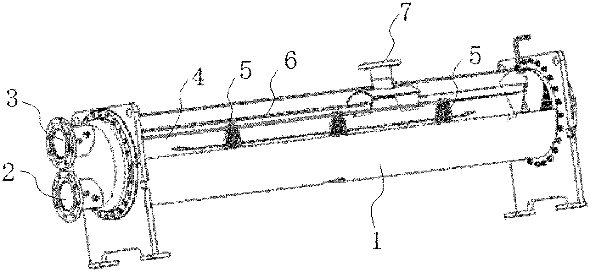
[0003] FIG. 1 shows a structure diagram of a condenser known to the inventors. As shown in FIG. 1, an air conditioner condenser known to the inventors includes a housing 1, and an inlet 2 and an outlet 3 disposed on the housing 1. Both the inlet 2 and the outlet 3 are disposed on a first end of the housing 1. The condenser further includes a first pipeline and a second pipeline disposed in the housing 1. A first end of the first pipeline communicates with the inlet 2, a first end of the second pipeline communicates with the outlet, and a second end of the second pipeline communicates with a second end of the first pipeline.
[0004] There is also a support plate 5 for supporting the first pipeline and the second pipeline arranged in the housing 1. A first hole matching with the first pipeline and a second hole matching with the second pipeline are disposed on the support plate 5. The first pipeline is disposed in the first hole in a penetrating manner, and the second pipeline is disposed in the second hole in a penetrating manner.
[0005] There are a plurality of first pipelines, and all the first ends of the plurality of first pipelines communicate with the inlet 2. There are a plurality of second pipelines, and all the first ends of the plurality of second pipelines communicate with the outlet 3.
[0006] There is also an oil separator 4 arranged in the housing 1. The oil separator 4 is on the inner top of the housing 1 of the condenser.
[0007] FIG. 2 shows a structure diagram of a oil separator known to the inventors. As shown in FIG. 2, the oil separator includes a chamber. A gas inlet 7 for introducing a refrigerant to be separated and a gas outlet 6 for outputting the separated refrigerant are disposed on the chamber. The gas inlet 7 and the gas outlet 6 are arranged on a same side face of the chamber. In some embodiments, both the gas inlet 7 and the gas outlet 6 are disposed on an upper end of the chamber.
[0008] An exhaust port of a compressor communicates with the gas inlet 7 of the oil separator 4. The refrigerant separated by the oil separator 4 is discharged from gas outlet 6 to the inner cavity of the housing 1 of the condenser, and performs heat exchange with a medium in the first pipeline and the second pipeline.
[0009] As shown in FIG. 2, a width of the chamber shrinks along the direction away from the gas outlet 6. An end, away from the gas outlet 6, of the chamber is provided with an oil drainage port 9 for draining an oil separated from the refrigerant.
[0010] The refrigerant changes a flow direction after entering the chamber through the gas inlet 7, and finally flows out from the chamber of the oil separator 4 through the gas outlet 6. In a process of the refrigerant changing the flow direction, the oil is separated from the refrigerant under the inertia effect. In order to further improve a separation efficiency of the oil separator 4, there is a filter component 8 disposed at the gas outlet 6, to further separate the oil in the refrigerant.
[0011] Pressures of airflow in areas at different distances from the gas outlet 6 and the gas inlet 7 are different too. In order to ensure that the separation efficiencies of the refrigerants output from all the areas of the gas outlet 6 achieve a predetermined effect, filtering performance of the filter component 8 is designed by the standard of a requirement of the area with the maximum pressure of airflow. Therefore, in the area with the relatively low pressure of airflow, the performance of the filter component 8 causes an unnecessary waste, and the filter component in the area produces unnecessary resistance to airflow. Therefore, the filter component 8 with single performance arranged at the outlet of the oil separator 4 is an unnecessary waste for the area with relatively low pressure of airflow, and causes an airflow blockage to the area with relatively low pressure of airflow.
SUMMARY
[0012] Some embodiments of the disclosure provide an air conditioner oil separator, a condenser and an air conditioner, to alleviate a problem in an air conditioner oil separator known to inventors that a filter component with single performance is not adaptable to requirements of areas at different distances from an inlet.
[0013] Some embodiments of the disclosure provide an air conditioner oil separator. The air conditioner oil separator includes a gas inlet for introducing a refrigerant to be separated, a gas outlet for outputting a separated refrigerant, and a filter component disposed at the gas outlet. The filter component includes:
[0014] a first filter area;
[0015] a second filter area, which is closer to the gas inlet than the first filter area; and
[0016] a third filter area, which is closer to the gas inlet than the second filter region; wherein a refrigerant separation efficiency of the first filter area is lower than a refrigerant separation efficiency of the second filter area; and/or, a refrigerant separation efficiency of the third filter area is lower than the refrigerant separation efficiency of the second filter area.
[0017] In an exemplary embodiment, the separation efficiency of the third filter area for the refrigerant is higher than a separation efficiency of the first filter area for the refrigerant.
[0018] In an exemplary embodiment,
[0019] a thickness or a density of a filter component of the second filter area is greater than that of a filter component of the first filter area;
[0020] the thickness or the density of the filter component of the second filter area is greater than that of a filter component of the third filter area; and
[0021] the thickness or the density of the filter component of the third filter area is greater than that of the filter component of the first filter area.
[0022] In an exemplary embodiment,
[0023] a material of the second filter area is different from a material of the first filter area, so that a separation efficiency of the second filter area is greater than a separation efficiency of the first filter area;
[0024] a material of the second filter area is different from a material of the third filter area, so that the separation efficiency of the second filter area is greater than a separation efficiency of the third filter area; and
[0025] the material of the third filter area is different from the material of the first filter area, so that the separation efficiency of the third filter area is greater than the separation efficiency of the first filter area.
[0026] In an exemplary embodiment, the gas outlet includes a first gas outlet and a second gas outlet respectively at two sides of the gas inlet.
[0027] In an exemplary embodiment, both the gas inlet and the gas outlet are disposed on a top of the air conditioner oil separator.
[0028] In an exemplary embodiment, the first filter area, the second filter area and the third filter area are arranged side by side in a direction close to the gas inlet.
[0029] Some embodiments of the present disclosure provide a condenser. The condenser includes:
[0030] a housing,
[0031] the air conditioner oil separator being disposed in the housing, and the gas outlet communicating with an inner cavity of the housing; and
[0032] a pipeline, which is disposed in the housing and is used for a medium for heat exchange with the refrigerant discharged from the gas outlet to flow.
[0033] In an exemplary embodiment, the pipeline includes:
[0034] a first pipeline, a first end of the first pipeline being used for introducing the medium for heat exchange with the refrigerant; and
[0035] a second pipeline, a first end of the second pipeline being used for outputting a medium after heat exchange with the refrigerant; a second end of the second pipeline communicates with a second end of the first pipeline.
[0036] In an exemplary embodiment, the first pipeline and the second pipeline are respectively disposed at two sides of the air conditioner oil separator.
[0037] Some embodiments of the present disclosure provide an air conditioner, the air conditioner includes:
[0038] a compressor, which is provided with a gas outlet for outputting compressed refrigerant; and
[0039] the air conditioner oil separator, wherein the gas inlet of the air conditioner oil separator communicates with an exhaust port of the compressor.
[0040] According to some embodiments of the present disclosure, by setting corresponding filter areas according to the pressures of airflow of different positions, the problem of waste caused by excess capacity of the filter component is alleviated, and it is beneficial to uniformity of gas pressures in different areas of the gas outlet.
[0041] Other characteristics and advantages of the disclosure will become clear by describing the exemplary embodiments of the disclosure in detail with reference to the following accompanying drawings.
BRIEF DESCRIPTION OF THE DRAWINGS
[0042] In order to more clearly illustrate technical solutions in the embodiments of the disclosure or the technology known to inventors, the accompanying drawings needed in description of the embodiments or the technology known to inventors are simply introduced below. It is apparent that the accompanying drawings in the following description are only some embodiments of the disclosure, for the ordinary skill in the art, some other accompanying drawings are also obtained according to these on the premise of not contributing creative effort.
[0043] FIG. 1 illustrates a structure diagram of a condenser of an air conditioner known to inventors.
[0044] FIG. 2 illustrates a structure diagram of an oil separator in a condenser of an air conditioner known to inventors.
[0045] FIG. 3 illustrates a structure diagram of an air conditioner oil separator according to an embodiment of the disclosure.
[0046] FIG. 4 illustrates a partial enlarged drawing of FIG. 3.
[0047] The above accompanying drawings include the following reference numbers:
[0048] 1, chamber; 2, gas inlet; 3, filter component; 31, first filter area; 32, second filter area; 33, third filter area; 4, baffle.
DETAILED DESCRIPTION OF THE EMBODIMENTS
[0049] The technical solutions in the embodiments of the disclosure will be clearly and fully described below in combination with the drawings in the embodiments of the disclosure. It is apparent that the described embodiments are not all embodiments but part of embodiments of the disclosure. The description of at least one exemplary embodiment below is actually just illustrative, and is never seen as any limit to the disclosure and its application or use. Based on the embodiments of the disclosure, all the other embodiments obtained by those of ordinary skill in the art on the premise of not contributing creative effort should belong to the protection scope of the disclosure.
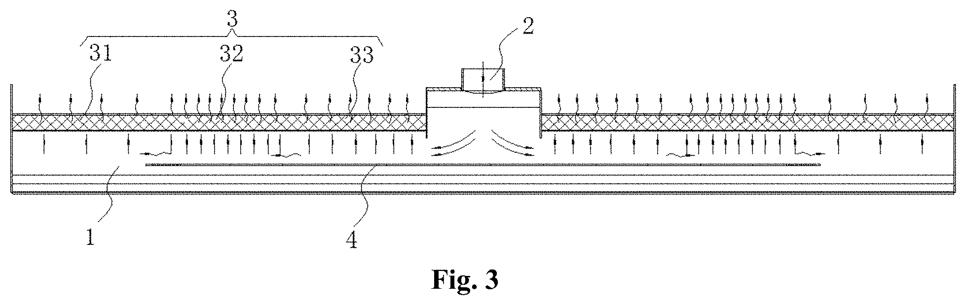
[0050] FIG. 3 illustrates a structure diagram of an air conditioner oil separator according to an embodiment. FIG. 4 illustrates a partial enlarged drawing of an air conditioner oil separator according to an embodiment.
[0051] In combination with FIG. 3 and FIG. 4, the air conditioner oil separator of some embodiments includes a chamber 1, a gas inlet 2 disposed on the chamber 1 and a gas outlet disposed on the chamber 1. The gas inlet 2 and the gas outlet are arranged on a same side face of the chamber 1. The gas outlet is provided with a filter component 3. The filter component 3 is configured to filter oil mixed in a refrigerant.
[0052] The gas outlet extends in a length direction of the oil separator. In some embodiments, the gas outlet includes a first gas outlet and a second gas outlet respectively disposed at two sides of the gas inlet 2, to shorten a length of each gas outlet, thus a pressure difference of airflow between the two gas outlets is reduced.
[0053] In some embodiments, the air conditioner oil separator further includes a baffle 4 disposed in the chamber 1. The baffle 4 is opposite to the gas inlet 2. After entering the chamber 1, the refrigerant to be separated first impacts with the baffle 4. After the refrigerant to be separated impacts with the baffle 4, because oil and gaseous refrigerant have different inertias, the oil and the gaseous refrigerant are separated for the first time.
[0054] After the first separation, the refrigerant mixed with less oil moves to the two sides of the gas inlet 2, and then enters the condenser after being filtered by the filter component 3, and performs heat exchanger with other media in the condenser.
[0055] Because of an inertia effect of airflow, pressures of airflow of various areas in a direction away from the gas inlet 2 in the chamber 1 are different. If the filter component 3 with single performance is adopted, because the pressures of the airflows passing through the various areas of the filter component 3 are different, correspondingly the pressures of the airflows after passing through the filter component 3 are not uniform.
[0056] In some embodiments, the performance of the filter component 3 is a separation efficiency of the filter component, namely a ratio between oil content of the refrigerant before passing through the filter component 3 and oil content of the refrigerant after passing through the filter component 3. Generally, the greater a thickness of the filter component 3, the higher the separation efficiency, correspondingly, the greater the resistance to the refrigerant; the greater the density of the filter component 3, the higher the separation efficiency, correspondingly, the greater the resistance to the refrigerant. In some embodiments, the separation efficiency of the filter component 3 is also related to the material of the filter component 3.
[0057] In order to ensure that a filtering effect of the filter component 3 on the refrigerant at any position achieves a predetermined requirement, the performance of the filter component 3 with single performance is often designed to the highest requirements. The better the filtering performance of the filter component 3, the greater the resistance to the airflow of the refrigerant, so the resistance of the filter component 3 to the refrigerant in an area with relatively low pressure of airflow is too great.
[0058] To solve the above problem, the filter component 3 of some embodiments includes a first filter area 31, a second filter area 32 and a third filter area 33 sequentially disposed in a direction close to the gas inlet 2. The third filter area 33 is close to the gas inlet 2. The third filter area 33 is also a filter area closest to the gas inlet 2 of multiple filter areas.
[0059] At a position close to the gas inlet 2, most refrigerants flow towards the direction away from the gas inlet 2, and the rest refrigerants flow out from the oil separator through the third filter area 33. As the refrigerant flows away from the gas inlet 2, more refrigerants flow out from the oil separator through the second filter area 32; therefore, a pressure of airflow of the refrigerant in the third filter area 33 is lower than that in the second filter area 32. As the refrigerant flows away from the gas inlet 2, the pressure of airflow of the refrigerant gets lower and lower; therefore, the pressure of airflow of the refrigerant in the first filter area 31 is lower than that in the second filter area 32.
[0060] In order to adapt the separation efficiency of each filter area to the pressure of airflow of the refrigerant, in some embodiments, a separation efficiency of the first filter area 31 for a refrigerant is lower than that of the second filter area 32 for a refrigerant, and the separation efficiency of the third filter area 33 for a refrigerant is lower than that of the second filter area 32 for a refrigerant.
[0061] In some embodiments, the separation efficiency of the third filter area 33 for the refrigerant is higher than that of the first filter area 31 for the refrigerant.
[0062] In some embodiments, by setting the filter components with corresponding performances according to the pressures of airflow of various areas in the direction away from the gas inlet 2, the performance of the filter component is fully used, and it is beneficial to ensuring the uniformity of the pressures of airflow output by various areas of the gas outlet.
[0063] As shown in FIG. 4, in some embodiments, the gas outlet with a length L is divided into the first filter area 31, the second filter area 32 and the third filter area 33. All the sizes, in the direction away from the gas inlet 2, of the first filter area 31, the second filter area 32 and the third filter area 33 are 1/3L.
[0064] The thicknesses and the materials of the filter components of the first filter area 31, the second filter area 32 and the third filter area 33 are the same. The densities of the first filter area 31, the second filter area 32 and the third filter area 33 are respectively H.sub.1, H.sub.2 and H.sub.3. The separation efficiencies of the first filter area 31, the second filter area 32 and the third filter area 33 are respectively E.sub.1, E.sub.2 and E.sub.3. Wherein, H.sub.2>H.sub.3>H.sub.1, and E.sub.2>E.sub.3>E.sub.1. The filter component made of the material with a higher separation efficiency or a greater density is disposed at the position bearing a larger impact of airflow or close to the gas inlet 2, and the filter component made of the material with a lower separation efficiency or a less density is disposed at the position bearing a smaller impact of airflow or away from the gas inlet. Thus, improves the degree of uniform distribution of airflow and reduces the pressure drop.
[0065] In some embodiments, the thicknesses of the filter components of the first filter area 31, the second filter area 32 and the third filter area 33 are the same, but the materials are different, so that E.sub.2>E.sub.3>E.sub.1.
[0066] In some embodiments, the densities and materials of the filter components of the first filter area 31, the second filter area 32 and the third filter area 33 are the same, but the thicknesses are different, so that E.sub.2>E.sub.3>E.sub.1.
[0067] In some embodiments, a width of the chamber 1 shrinks along the direction away from the filter component 3. An end, away from the filter component 3, of the chamber 1 is provided with an oil drainage port. The filter component 3 is disposed on a top of the chamber 1. The oil separated by the oil separator gathers at a bottom of the chamber 1, and the gathered oil is drained through the oil drainage port.
[0068] According to another aspect of the disclosure, some embodiments also provide a condenser. The condenser includes a housing and the air conditioner oil separator. The air conditioner oil separator is disposed in the housing. There is also a pipeline for the medium for heat exchange to flow arranged in the housing. The refrigerant discharged from the oil separator flows in an inner cavity of the housing, and performs heat exchange with the medium for heat exchange in the pipeline.
[0069] In some embodiments, the pipeline includes a first pipeline and a second pipeline. A first end of the first pipeline is used for introducing the medium for heat exchange with the refrigerant, and a first end of the second pipeline is used for outputting the medium after heat exchange with the refrigerant. A second end of the second pipeline communicates with a second end of the first pipeline.
[0070] There are a plurality of first pipelines and a plurality of second pipelines. A first end of a housing of the condenser is provided with a medium inlet and a medium outlet. The first ends of the plurality of first pipelines communicate with the medium inlet, and the second ends of the plurality of second pipelines communicate with the medium outlet.
[0071] In some embodiments the first pipeline and the second pipeline are respectively arranged at two sides of the air conditioner oil separator.
[0072] Some embodiments of the present disclosure also provide an air conditioner. The air conditioner includes a compressor and the condenser. An exhaust port of the compressor communicates with the gas inlet 2 of the air conditioner oil separator.
[0073] The above is only some embodiments of the disclosure and not intended to limit the disclosure. Any modifications, equivalent replacements, improvements and the like made within the spirit and principle of the disclosure shall fall within the scope of protection of the disclosure.
* * * * *
D00000
D00001
D00002
D00003
D00004
XML
uspto.report is an independent third-party trademark research tool that is not affiliated, endorsed, or sponsored by the United States Patent and Trademark Office (USPTO) or any other governmental organization. The information provided by uspto.report is based on publicly available data at the time of writing and is intended for informational purposes only.
While we strive to provide accurate and up-to-date information, we do not guarantee the accuracy, completeness, reliability, or suitability of the information displayed on this site. The use of this site is at your own risk. Any reliance you place on such information is therefore strictly at your own risk.
All official trademark data, including owner information, should be verified by visiting the official USPTO website at www.uspto.gov. This site is not intended to replace professional legal advice and should not be used as a substitute for consulting with a legal professional who is knowledgeable about trademark law.