Scroll Compressor
Kind Code
U.S. patent application number 16/776937 was filed with the patent office on 2020-08-06 for scroll compressor. This patent application is currently assigned to LG ELECTRONICS INC.. The applicant listed for this patent is LG ELECTRONICS INC.. Invention is credited to Yicheol CHOI, Sang Hyun JOO, Junyoung LIM, IL Young PARK.
| Application Number | 20200248691 16/776937 |
| Document ID | / |
| Family ID | 1000004645089 |
| Filed Date | 2020-08-06 |


| United States Patent Application | 20200248691 |
| Kind Code | A1 |
| PARK; IL Young ; et al. | August 6, 2020 |
SCROLL COMPRESSOR
Abstract
A scroll compressor includes a main housing. A driving part configured to generate torque and a compression part driven by the driving part are accommodated in the main housing. The compression part includes a fixed scroll and an orbiting scroll that engages with the fixed scroll to form a compression chamber in which a refrigerant is compressed. The torque of the driving part is transmitted to the compression part by a driving shaft. The driving shaft is rotatably supported by a main bearing positioned in a low pressure region adjacent to the driving part. Accordingly, since the main bearing is disposed in a low pressure region, a load applied to the main bearing may be decreased.
| Inventors: | PARK; IL Young; (Seoul, KR) ; CHOI; Yicheol; (Seoul, KR) ; JOO; Sang Hyun; (Seoul, KR) ; LIM; Junyoung; (Seoul, KR) | ||||||||||
| Applicant: |
|
||||||||||
|---|---|---|---|---|---|---|---|---|---|---|---|
| Assignee: | LG ELECTRONICS INC. Seoul KR |
||||||||||
| Family ID: | 1000004645089 | ||||||||||
| Appl. No.: | 16/776937 | ||||||||||
| Filed: | January 30, 2020 |
| Current U.S. Class: | 1/1 |
| Current CPC Class: | F04C 29/0057 20130101; F04C 2240/56 20130101; F04C 25/00 20130101; F04C 18/0215 20130101; F04C 27/009 20130101; F04C 2210/261 20130101 |
| International Class: | F04C 27/00 20060101 F04C027/00; F04C 25/00 20060101 F04C025/00; F04C 29/00 20060101 F04C029/00; F04C 18/02 20060101 F04C018/02 |
Foreign Application Data
| Date | Code | Application Number |
|---|---|---|
| Feb 1, 2019 | KR | 10-2019-0014114 |
Claims
1. A scroll compressor comprising: a main housing including an accommodation space and a refrigerant suction hole configured to introduce a low pressure refrigerant into the accommodation space; a driving part including a driving motor accommodated in the main housing; a driving shaft coupled to the driving motor; a compression part including a fixed scroll accommodated in the main housing and an orbiting scroll engaged with the fixed scroll to form a high pressure compression chamber; a main frame disposed between the driving part and the compression part and configured to divide an interior of the main housing into a low pressure region and a high pressure region, the driving part being disposed in the low pressure region and the compression part being disposed in the high pressure region; and a main bearing attached to the main frame in the low pressure region and configured to rotatably support the driving shaft.
2. The scroll compressor of claim 1, further including: a medium pressure chamber (MR) disposed between the compression part and the main frame, such that the main bearing is disposed outside the medium pressure chamber (MR).
3. The scroll compressor of claim 2, wherein the main frame includes: a circular plate portion disposed between the driving part and the compression part; and a bearing accommodation portion disposed between the circular plate portion and the driving part and coupled to the main bearing.
4. The scroll compressor of claim 3, wherein: the medium pressure chamber (MR) is formed in the circular plate portion; and the bearing accommodation portion protrudes from the circular plate portion toward the driving part and is disposed in the low pressure region.
5. The scroll compressor of claim 4, wherein: the bearing accommodation portion includes a seat groove; the main bearing is disposed in the seat groove, and a sealing member is disposed between the medium pressure chamber (MR) and the main bearing and configured to prevent a refrigerant from flowing between the medium pressure chamber (MR) and the main bearing.
6. The scroll compressor of claim 5, wherein the bearing accommodation portion includes an opening having one end connected to the low pressure region adjacent to the driving motor and an opposite end connected to the medium pressure chamber (MR) separated from low pressure region by the sealing member.
7. The scroll compressor of claim 5, wherein an inner circumferential surface of the opening includes a groove, and the sealing member is seated in the groove.
8. The scroll compressor of claim 7, wherein the seat groove includes a generally concave inner surface along a direction from adjacent to the driving part towards the compression part.
9. The scroll compressor of claim 7, wherein: the groove is disposed between the circular plate portion and the seat groove; and a diameter of the seat groove is greater than a diameter of the groove.
10. The scroll compressor of claim 1, wherein the main frame includes: a circular plate portion disposed between the driving part and the compression part; and a bearing accommodation portion disposed between the circular plate portion and the driving part.
11. The scroll compressor of claim 10, wherein: an interior of the bearing accommodation portion is connected to the low pressure region; and the main bearing is accommodated in the bearing accommodation portion.
12. The scroll compressor of claim 11, wherein: the bearing accommodation portion protrudes from the circular plate portion toward the driving part; and the interior of the bearing accommodation portion is open toward the driving part and is connected to the low pressure region.
13. The scroll compressor of claim 12, further comprising: a medium pressure chamber (MR) disposed between the bearing accommodation portion and the compression part; and a sealing member disposed in the bearing accommodation portion between the medium pressure chamber (MR) from the low pressure region, wherein the main bearing is disposed in a portion of the bearing accommodation portion connected to the low pressure region.
14. The scroll compressor of claim 1, wherein: a medium pressure chamber (MR) is formed in the main frame; and the main bearing is disposed outside the medium pressure chamber (MR) and between the medium pressure chamber (MR) and the driving part.
15. The scroll compressor of claim 1, wherein the refrigerant includes a carbon dioxide refrigerant.
16. A scroll compressor comprising: a main housing; a driving motor disposed in the main housing; a driving shaft coupled to the driving motor; a fixed scroll attached to the main housing; an orbiting scroll connected to the driving shaft, the orbiting scroll forming a high pressure compression chamber with the fixed scroll; a main frame disposed between the driving motor and the orbiting scroll and configured to divide an interior of the main housing into a low pressure region and a high pressure region, the main frame including a seat groove disposed in the low pressure region; and a main bearing disposed in the seat groove and configured to rotatably support the driving shaft.
17. The scroll compressor of claim 16, wherein the main frame includes: a circular plate portion; and a bearing accommodation portion protruding from the circular plate portion towards the driving motor.
18. The scroll compressor of claim 17, wherein the circular plate portion includes a medium pressure chamber, the bearing accommodation portion includes an opening extending from the seat groove to the medium pressure chamber, and the driving shaft extends through the opening.
19. The scroll compressor of claim 18, further including a sealing member disposed in the bearing accommodation portion between the seat groove and the medium pressure chamber.
20. The scroll compressor of claim 18, further including a groove extending radially from an inner circumferential surface of the opening into the bearing accommodation portion, the groove being configured to receive the sealing member.
Description
CROSS-REFERENCE TO RELATED APPLICATION
[0001] This application claims priority to and the benefit of Korean Patent Application No. 2019-0014114, filed on Feb. 1, 2019, the disclosure of which is incorporated herein by reference in its entirety.
BACKGROUND
1. Field of the Invention
[0002] The present invention relates to a scroll compressor.
2. Discussion of Related Art
[0003] Compressors refer to apparatuses configured to compress refrigerants. The compressors may be divided into reciprocating type, centrifugal type, vane type, and scroll type compressors.
[0004] Among them, the scroll type compressor (hereinafter, scroll compressor) includes a fixed scroll and an orbiting scroll. The fixed scroll is fixed in an inner space of a sealed container and the orbiting scroll is engaged with the fixed scroll and performs an orbital movement. A fixed wrap protruding toward the orbiting scroll is provided to the fixed scroll. An orbiting wrap protruding toward the fixed scroll is provided to the orbiting scroll. A compression chamber may be formed in the scroll compressor. The compression chamber may be formed between the fixed wrap and the orbiting wrap when the orbiting scroll orbits the fixed scroll, and a refrigerant may be compressed in the compression chamber.
[0005] The scroll compressor may obtain a relatively higher compression ratio than other kinds of compressors. In addition, the scroll compressor has an advantage of obtaining stable torque because refrigerant suction, refrigerant compression, and refrigerant discharge strokes are serially performed smoothly. Accordingly, the scroll compressor is being widely used to compress the refrigerant in various fields.
[0006] One example of the scroll compressor is disclosed in Korean Patent Registration No. 10-0937919 (Registration date, Jan. 13, 2010, hereinafter, numerals for illustrating a scroll compressor of the related art are numerals disclosed in the patent which only correspond to description for the related art).
[0007] A conventional scroll compressor includes a driving part configured to generate torque and a scroll compression part configured to compress a refrigerant.
[0008] The driving part includes a driving motor including a stator 210 and a rotor 220 which are provided in a housing H, and a driving shaft 200 inserted into a central portion of the driving motor to rotate. A main bearing 240 and a sub-bearing 250 are installed at one side of the driving shaft 200, and a rear bearing 730 is installed at the other side thereof to rotatably support the driving shaft 200. The main bearing 240 is inserted into a main frame 860.
[0009] The scroll compression part includes an orbiting scroll 400 and a fixed scroll 500. The fixed scroll 500 is fixed to the main frame 860. The fixed scroll 500 includes a scroll wrap 510 for compressing a refrigerant. The orbiting scroll 400 is coupled to the fixed scroll 500. The orbiting scroll 400 includes a scroll wrap 410 coupled to the scroll wrap 510 to compress the refrigerant. The orbiting scroll 400 rotates due to the driving shaft 200 and compresses the refrigerant while orbiting.
[0010] A back pressure chamber BAC is formed between the orbiting scroll 400 and the main frame 860. A back pressure is generated in the back pressure chamber BAC so that the orbiting scroll 400 is pressed against the fixed scroll 500.
[0011] A discharge chamber 610 to which the compressed refrigerant is discharged is formed in the front of the housing H. In addition, a suction chamber 710 into which the refrigerant is suctioned is formed in the rear of the housing H. The refrigerant suctioned into the suction chamber 710 is compressed while passing through the driving part and the scroll compression part and is discharged to the discharge chamber 610. Among pressures in the housing H, a pressure in the suction chamber 710 is lowest, a pressure in the discharge chamber 610 is highest, and a pressure in the back pressure chamber BAC is about medium.
[0012] The above-described conventional scroll compressor is a compressor which is applied to an air conditioning system of a vehicle and typically uses R134a or R1234yf refrigerant (a kind of a chemical refrigerant). Such a chemical refrigerant is a refrigerant for generating an internal pressure ranging from a minimum of 2 bars to a maximum of 30 bars of a scroll compressor. In the case of the scroll compressor using a lower pressure refrigerant, even when a main bearing is positioned at a side of a back pressure chamber like the above-described related patent document, a pressure applied to the main bearing is not high. Accordingly, it may satisfy an endurance lifespan of the bearing based on industry standards.
[0013] However, a demand for a natural refrigerant or eco-friendly refrigerant is increasing due to a change in awareness of environmental pollution, and various regulations on exhaust gas are being introduced. According to such a trend, an interest in an eco-friendly refrigerant using carbon dioxide as a refrigerant is increasing.
[0014] In the case of carbon dioxide, carbon dioxide is used in an environment in which a minimum pressure of 35 bars increases to a maximum operating pressure of 130 bars in a scroll compressor. Accordingly, components such as a main bearing are exposed to an environment at a higher pressure than a conventional environment in which the low pressure refrigerant is used. Accordingly, a load applied to the main bearing increases, and thus there is a problem in that a lifespan of the main bearing is significantly decreased.
[0015] Accordingly, since it is difficult to satisfy a required durability lifespan based on industry regulations, the durability of the main bearing should be further improved. As an example, there is a method of improving the durability of the main bearing by increasing a size of the main bearing or performing a specific treatment on the main bearing. However, due to interference with a periphery thereof, it is not easy to increase the size of the main bearing. In addition, in the case in which the specific treatment is performed on the main bearing, a manufacturing cost is increased.
[0016] In addition, there is a method of increasing the durability lifespan of the main bearing by decreasing a temperature of the periphery. However, since the main bearing is disposed in a medium pressure chamber, it is difficult to form a cooling structure around the main bearing.
SUMMARY OF THE INVENTION
[0017] The present invention is directed to providing a scroll compressor with an improved structure capable of improving the durability of a main bearing by reducing a load applied to a main bearing in a high pressure refrigerant compressing environment.
[0018] In addition, the present invention is directed to providing a scroll compressor with an improved structure capable of improving the durability of a main bearing by increasing a size of the main bearing.
[0019] In addition, the present invention is directed to providing a scroll compressor with an improved structure capable of improving the durability of main bearing by decreasing a temperature of a periphery of the main bearing.
[0020] Objectives of the present invention are not limited to the above described objectives, and other objectives, which are not described above, and advantages of the present invention may be more clearly understood through the following descriptions and clearly understood through embodiments of the present invention. In addition, it may be easily seen that the objectives and the advantages of the present invention may be easily realized using means and combinations thereof described in the appended claims.
[0021] A scroll compressor according to one embodiment of the present invention for achieving the above-described purposes includes a main frame which divides an interior of a main housing into a low pressure region in which a driving part is disposed and a high pressure region in which a compression part is disposed and a main bearing which is installed in the main frame, rotatably supports a driving shaft, and is disposed in the low pressure region.
[0022] Since the main bearing is disposed in the low pressure region as described above, a load applied to the main bearing can be decreased, and thus an increase in durability lifespan of the main bearing can be expected.
[0023] In addition, according to another embodiment of the present invention, a main bearing is disposed outside a medium pressure chamber.
[0024] In addition, according to another embodiment of the present invention, the main bearing is disposed in a bearing accommodation portion, and a sealing member is disposed between the main bearing and the medium pressure chamber to block the medium pressure chamber from a low pressure region.
[0025] In addition, according to another embodiment of the present invention, the main bearing is disposed in the bearing accommodation portion and is disposed in a space blocked from the medium pressure chamber by a sealing member.
[0026] In addition, according to another embodiment of the present invention, the main bearing is disposed outside the medium pressure chamber and is disposed in a space between the medium pressure chamber and a driving part.
[0027] Accordingly, the main bearing may be disposed in the low pressure region having a relatively wider space than a region of the medium pressure chamber. Therefore, since a size of the main bearing can be increased easily, the main bearing having high durability even in a high pressure environment can be provided.
[0028] According to an aspect of the present invention, there is provided a scroll compressor including a main housing forming an accommodation space and including a refrigerant suction hole through which a low pressure refrigerant is introduced, a driving part including a driving motor accommodated in the main housing and configured to generate torque and a driving shaft coupled to the driving motor to rotate, a compression part including a fixed scroll accommodated in the main housing and an orbiting scroll engaged with the fixed scroll to form a high pressure compression chamber, a main frame which is disposed between the driving part and the compression part and divides an interior of the main housing into a low pressure region in which the driving part is disposed and a high pressure region in which the compression part is disposed, and a main bearing which is installed in the main frame, rotatably supports the driving shaft, and is disposed in the low pressure region.
[0029] A medium pressure chamber may be disposed between the compression part and the main frame, and the main bearing may be disposed outside the medium pressure chamber.
[0030] The main frame may include a circular plate portion disposed between the driving part and the compression part, and a bearing accommodation portion disposed between the circular plate portion and the driving part and coupled to the main bearing.
[0031] The medium pressure chamber may be formed in the circular plate portion, and the bearing accommodation portion may protrude from the circular plate portion toward the driving part and may be disposed in the low pressure region.
[0032] An opening connected to the medium pressure chamber may be formed in the bearing accommodation portion, the main bearing may be disposed in the opening of the bearing accommodation portion, and a sealing member configured to prevent a refrigerant from moving between the medium pressure chamber and the main bearing may be formed between the medium pressure chamber and the main bearing.
[0033] The sealing member may be disposed in the opening of the bearing accommodation portion to seal an inner space of the bearing accommodation portion, and an inner space, which is close to the medium pressure chamber with respect to the sealing member, of the bearing accommodation portion may be connected to the medium pressure chamber and an inner space, which is close to the driving motor with respect to the sealing member, of the bearing accommodation portion may be connected to the low pressure region.
[0034] A seat groove in which the main bearing is seated and a groove in which the sealing member is seated may be formed in an inner circumferential surface of the bearing accommodation portion in the main housing.
[0035] The seat groove may be concavely formed in a direction from one side, which faces the driving part, of the bearing accommodation portion toward the compression part.
[0036] The seat groove may be concavely formed in the bearing accommodation portion to be open toward the driving part, the groove may be disposed between the circular plate portion and the seat groove, and a diameter of the seat groove may be greater than a diameter of the groove.
[0037] The main frame may include a circular plate portion disposed between the driving part and the compression part, and a bearing accommodation portion disposed between the circular plate portion and the driving part and coupled to the main bearing.
[0038] In addition, an interior of the bearing accommodation portion may be connected to the low pressure region, and the main bearing may be accommodated in the bearing accommodation portion.
[0039] The bearing accommodation portion may protrude from the circular plate portion toward the driving part, and the interior of the bearing accommodation portion may be open toward the driving part and may be connected to the low pressure region.
[0040] The scroll compressor may further include a medium pressure chamber disposed between the bearing accommodation portion and the compression part and a sealing member disposed in the bearing accommodation portion to block the medium pressure chamber from the low pressure region, wherein the main bearing may be disposed in a space blocked from the medium pressure chamber.
[0041] A medium pressure chamber may be formed in the main frame, and the main bearing may be disposed outside the medium pressure chamber and disposed in a space between the medium pressure chamber and the driving part.
[0042] The refrigerant may be a carbon dioxide refrigerant.
BRIEF DESCRIPTION OF THE DRAWINGS
[0043] The above and other objects, features and advantages of the present invention will become more apparent to those of ordinary skill in the art by describing exemplary embodiments thereof in detail with reference to the accompanying drawings, in which:
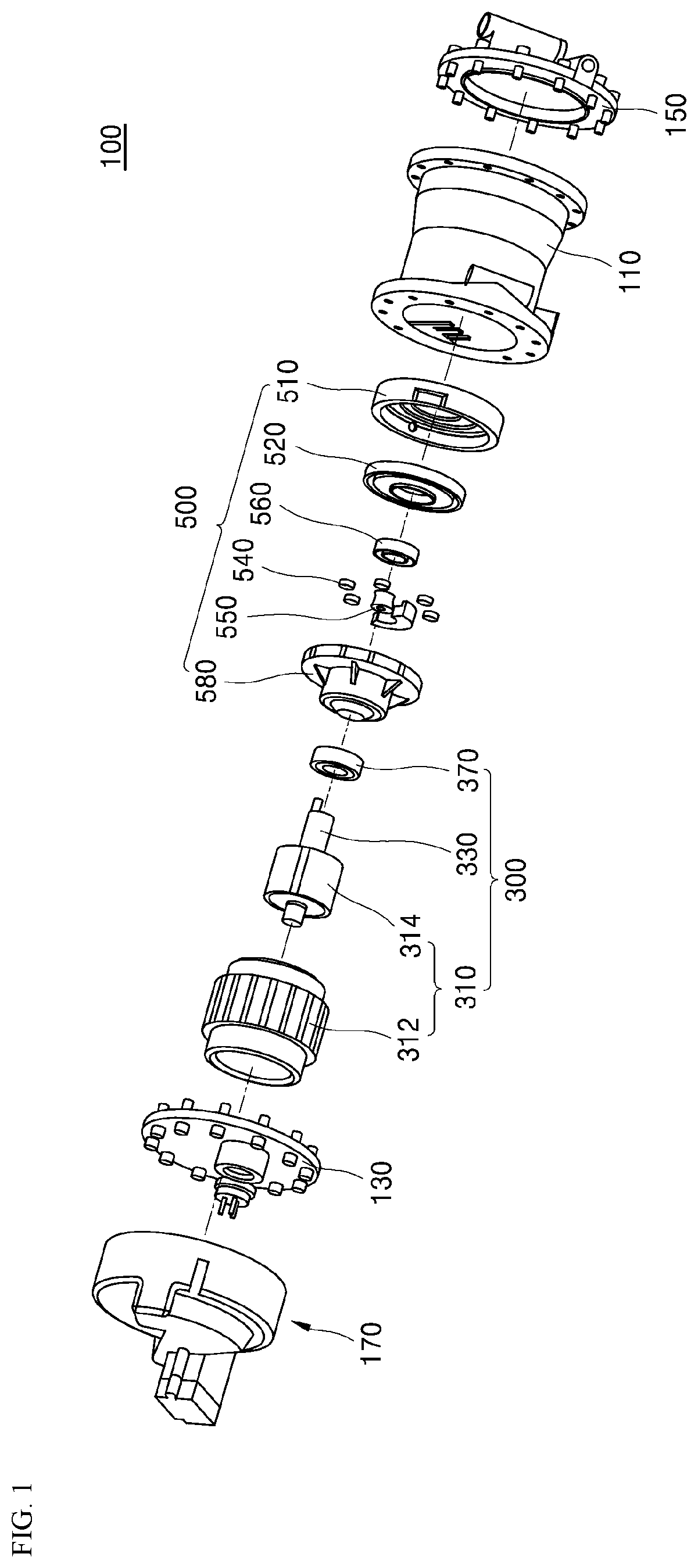
[0044] FIG. 1 is an exploded perspective view illustrating a scroll compressor according to one embodiment of the present invention;
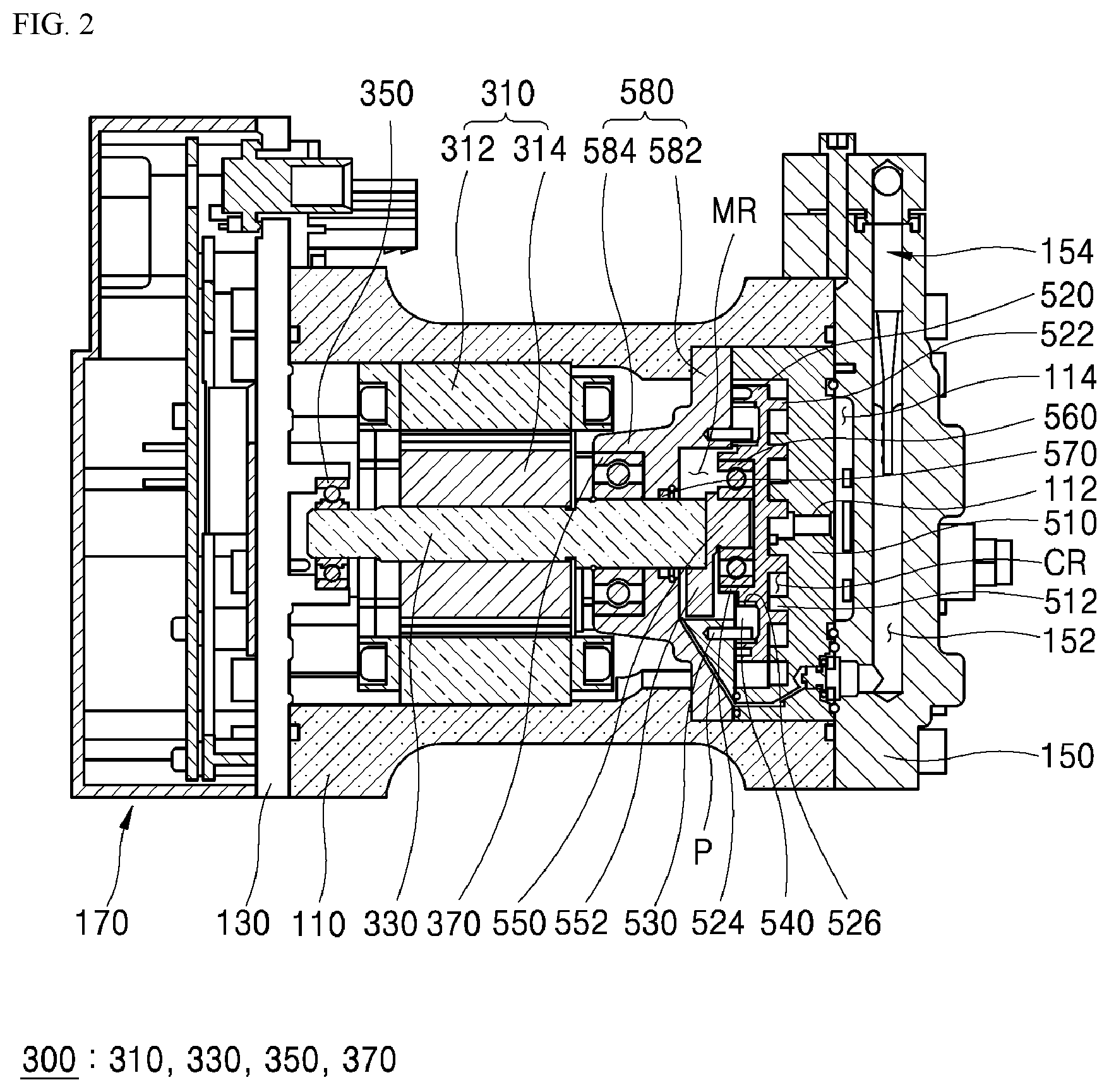
[0045] FIG. 2 is a cross-sectional view illustrating the scroll compressor according to FIG. 1;
[0046] FIG. 3 is an enlarged cross-sectional view illustrating an installation state of a main bearing according to FIG. 2;
[0047] FIG. 4 is a schematic view illustrating a main bearing and a sealing position of a conventional scroll compressor; and
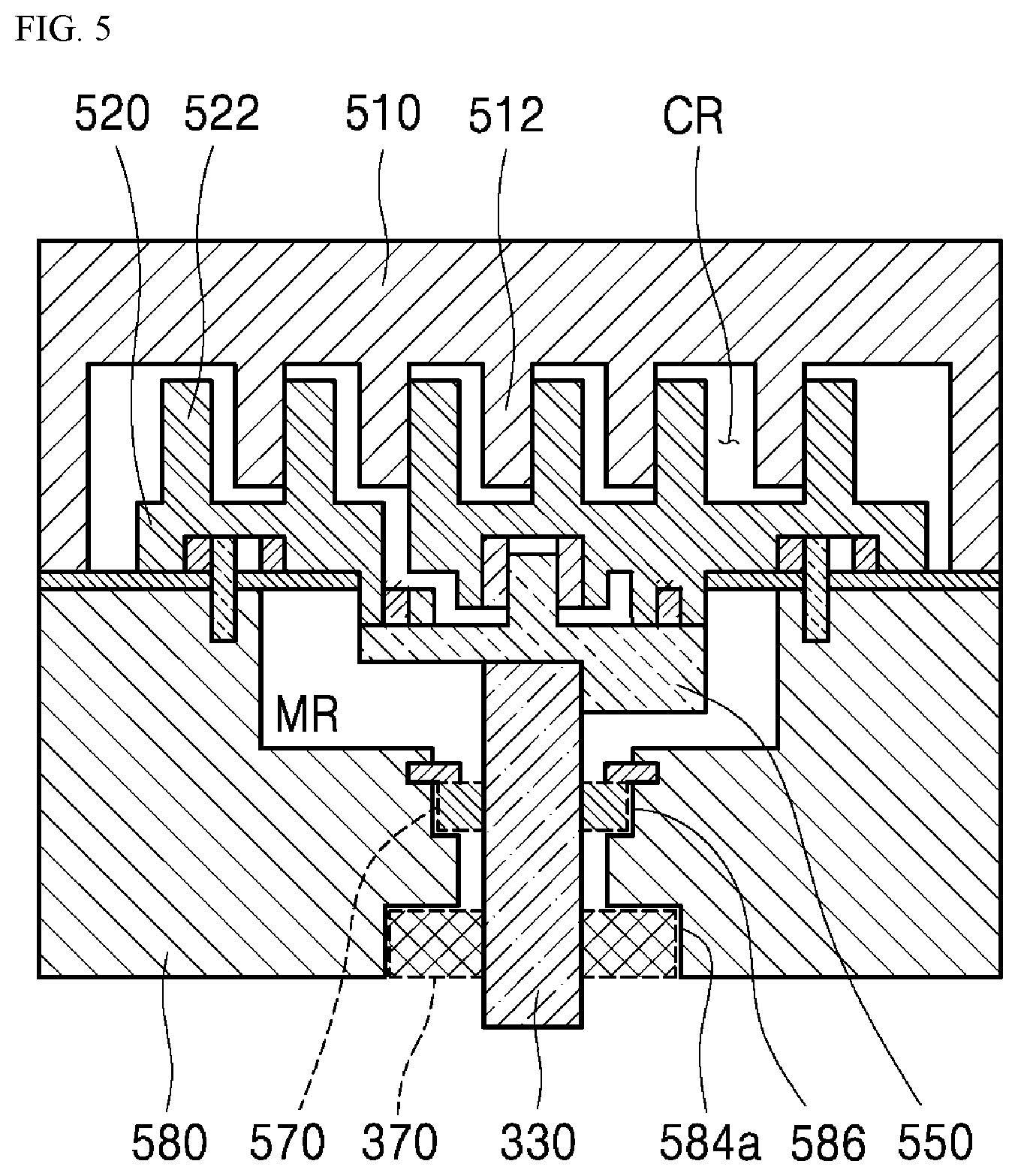
[0048] FIG. 5 is a schematic view illustrating the main bearing and a sealing position of the scroll compressor of the present invention.
DETAILED DESCRIPTION OF EXEMPLARY EMBODIMENTS
[0049] The above-described purposes, features, and advantages will be described in detail with reference to the accompanying drawings, and thus the technical spirit of the present invention may be easily executed by those skilled in the art. When it is determined that the detailed descriptions of related well-known technologies unnecessarily obscure the gist of the invention, the detailed descriptions will be omitted. Hereinafter, exemplary embodiments of the present invention will be described in detail with reference to the accompanying drawings. The same or similar elements are denoted by the same reference numerals in the drawings throughout this specification.
[0050] Although terms such as first, second, or the like may be used for describing various elements, the elements are not limited to the terms. The terms are only used to distinguish one element from another element, and unless otherwise specifically described, a first element may also be a second element.
[0051] Hereinafter, a case in which an arbitrary element is disposed "above (or under)" or "on (or below)" an element may include a case in which the arbitrary element is disposed to be in contact with an upper (or lower) surface of the element, or a case in which still another element may be interposed between the element and the arbitrary element disposed above (or under) the element.
[0052] It should be understood that, when an element is referred to as being "connected or coupled" to another element, the element may be directly connected or coupled to another element, still another element may be interposed therebetween, or the elements may be connected or coupled through still another element.
[0053] Throughout the specification, unless specifically described otherwise, the number of elements may be one or a plurality.
[0054] The singular forms "a," "an," and "the" used in the present specification are intended to include the plural forms as well, unless the context clearly indicates otherwise. It should be interpreted that the terms "comprises," "comprising," "includes," and/or "including," when used herein, do not necessarily include all components or various operations stated in the specification and may not include some components and operations therein or may further include additional components and operations.
[0055] Throughout the specification, unless otherwise specifically described, "A and/or B" refers to "A, B, or A and B," and "C to D" refers to "more than or equal to C and less than or equal to D"
[0056] FIG. 1 is an exploded perspective view illustrating a scroll compressor according to one embodiment of the present invention. FIG. 2 is a cross-sectional view illustrating the scroll compressor according to FIG. 1. FIG. 3 is an enlarged cross-sectional view illustrating an installation state of a main bearing according to FIG. 2.
[0057] As illustrated in FIGS. 1 and 2, a scroll compressor 10 according to one embodiment of the present invention includes a main housing 110 forming an accommodation space, and a front head 130 and a rear head 150 coupled to the front and the rear of the main housing 110 to cover the accommodation space. An inverter assembly 170 is coupled to the front of the front head 130. A driving part 300 and a compression part 500 are accommodated in the accommodation space (hereinafter, a direction toward the front head is defined as a forward direction and a direction toward the rear head is defined as a rearward direction. Accordingly, a surface positioned toward the front head of each component is a front surface thereof, and a surface positioned toward the rear head of each component is a rear surface thereof).
[0058] The main housing 110 has an exterior having a substantially cylindrical shape. In addition, the main housing 110 has a shape in which both ends are open in a longitudinal direction. The front head 130 and the rear head 150 are coupled to the both open ends. The front head 130 and rear head 150 have substantially circular plate shapes corresponding to shapes of end portions of the main housing 110.
[0059] A refrigerant suction hole (not shown) configured to suction a refrigerant and a refrigerant suction chamber (not shown) are formed at one front side of the main housing 110. A refrigerant discharge hole 112, through which a refrigerant compressed by the compression part 500 is discharged, and a refrigerant discharge chamber 114 are formed between the rear of the main housing 110 and the rear head 150. An oil storage portion 152 is formed in the rear head 150. An oil separator 154 configured to separate oil from the discharged refrigerant is installed in the oil storage portion 152.
[0060] The low temperature and low pressure refrigerant introduced through the refrigerant suction hole cools the driving part 300 while passing through a refrigerant suction chamber and moving from a front portion in the main housing toward a rear portion therein and is introduced into the compression part 500. The refrigerant introduced into the compression part 500 is compressed into a high temperature and high pressure state and discharged to the refrigerant discharge chamber 114 through the refrigerant discharge hole 112. The discharged refrigerant is separated from the oil in the oil separator 154 and discharged to the outside of the rear head 150. The oil separated in the oil separator 154 is supplied to a medium pressure chamber MR, which will be described below, from the oil storage portion 152 through an oil path P. The oil supplied to the medium pressure chamber MR lubricates portions of the compression part 500.
[0061] Among the above-described components included in the scroll compressor 100, the driving part 300 and the compression part 500 will be described in detail.
[0062] As illustrated in FIGS. 1 to 3, the driving part 300 includes a driving motor 310 configured to generate torque and a driving shaft 330 rotated by the driving motor 310.
[0063] The driving motor 310 includes a stator 312 fixedly installed in the main housing 110 and a rotor 314 which is inserted into the stator 312 and is rotated. The stator 312 may be formed to have a cylindrical shape. The stator 312 includes a plurality of slots around which coils are wound. The rotor 314 is rotated due to an electromotive force of a magnetic field generated by the stator 312. The driving shaft 330 is inserted into and passes through an inside of the rotor 314. The driving shaft 330 is rotated due to rotation of the rotor 314.
[0064] One side of the driving shaft 330 is fixed to the rotor 314, and the other side of the driving shaft 330 extends toward the compression part 500. One side of the driving shaft 330 may be rotatably supported by a front bearing 350. The other side of the driving shaft 330 may be rotatably supported by a main bearing 370.
[0065] The front bearing 350 is coupled to the front head 130 and rotatably supports the driving shaft 330. The main bearing 370 is coupled to the main housing 110 of the compression part 500, which will be described below, and rotatably supports the driving shaft 330 (the main bearing will be described below).
[0066] The compression part 500 may include a fixed scroll 510 fixed to the main housing 110 and an orbiting scroll 520 coupled to perform an orbital movement on the fixed scroll 510. In addition, the compression part 500 may further include a plurality of pins 530 and rings 540 configured to restrict rotation of the orbiting scroll 520. In addition, the compression part 500 may further include an eccentric bush 550, which causes the orbiting scroll 520 to orbit, and a sub-bearing 560 which rotatably supports the eccentric bush 550. In addition, the compression part 500 may further include a main frame 580 disposed between and coupled to the orbiting scroll 520 and the driving part 300 to support the driving shaft 330.
[0067] The fixed scroll 510 may be disposed close to the rear head 150. A rear surface of the fixed scroll 510 may be coupled to the rear head 150. The fixed scroll 510 may be formed to have a cylindrical shape in which a side toward the front head 130 is open. The fixed scroll 510 may include a fixed wrap 512 formed to protrude toward the front head 130.
[0068] The fixed wrap 512 may protrude from a front surface of the fixed scroll 510 to have a vortex shape. The fixed wrap 512 is coupled to the orbiting scroll 520 to form a compression chamber CR. An orbiting wrap 522 of the orbiting scroll 520, which will be described below, may be engaged with and coupled to the fixed wrap 512.
[0069] The orbiting scroll 520 may be formed to have a size less than a size of the fixed scroll 510 and coupled to the fixed scroll 510. The orbiting scroll 520 may be inserted into the fixed scroll 510 through the open side of the fixed scroll 510 to be coupled to the fixed scroll 510. The orbiting scroll 520 may be formed to have a circular plate shape having a predetermined thickness. The orbiting scroll 520 may include the orbiting wrap 522 protruding from a rear surface of the orbiting scroll 520, which faces the fixed wrap 512, of the orbiting scroll 520. A coupling portion 524 is formed to protrude from a front surface of the orbiting scroll 520, and the sub-bearing 560 may be coupled to the coupling portion 524. In addition, a plurality of pin and ring grooves 526 may be formed in the front surface of the orbiting scroll 520. The pins 530 and the rings 540 may be inserted into the pin and ring grooves 526.
[0070] The orbiting wrap 522 may protrude from the rear surface of the orbiting scroll 520 to have a vortex shape. The orbiting wrap 522 may be coupled to the fixed wrap 512 to form the compression chamber CR. The fixed wrap 512 may be engaged with and coupled to the orbiting wrap 522, and the compression chamber CR may be formed between the fixed wrap 512 and the orbiting wrap 522.
[0071] The bearing coupling portion 524 may protrude from a center of the front surface of the orbiting scroll 520. The bearing coupling portion 524 protrudes to have a cylindrical shape such that the sub-bearing 560 is inserted into the bearing coupling portion 524. The sub-bearing 560 may be inserted into and supported by the bearing coupling portion 524. An opening may be formed in the sub-bearing 560. The eccentric bush 550 may be inserted into the opening so that the eccentric bush 550 may be rotatably supported by the sub-bearing 560.
[0072] The plurality of pin and ring grooves 526 may be disposed in the front surface of the orbiting scroll 520 in a circumferential direction. The plurality of rings 540 may be inserted into the pin and ring grooves 526. The cylindrical pins 530 may be inserted into the rings 540. The pins 530 may be coupled to the main frame 580. The pins 530 come into contact with the rings 540 to restrict movement of the rings 540.
[0073] The eccentric bush 550 may be inserted into the front of the orbiting scroll 520. The eccentric bush 550 may be rotatably supported by the sub-bearing 560. The eccentric bush 550 may be formed to have a shape in which a weight 552 having an arc shape is connected to one side of a cylinder. Accordingly, the eccentric bush 550 has an eccentric rotating weight. The driving shaft 330 may be coupled to a central portion of the eccentric bush 550, and the sub-bearing 560 may be coupled to an outer circumferential surface of the eccentric bush 550. In this case, the outer circumferential surface of the eccentric bush 550 may be in contact with an inner circumferential surface of the sub-bearing 560. When the driving shaft 330 rotates, the eccentric bush 550 rotates together with the driving shaft 330. In this case, the eccentric bush 550 rotates in a state in which a center of gravity is eccentrically applied toward the weight 552. The orbiting scroll 520 may be prevented from self-orbiting by the eccentric bush 550, the pins 530, and the rings 540, and the orbiting scroll 520 may orbit the fixed scroll 510.
[0074] The main frame 580 may be disposed in front of the orbiting scroll 520 and coupled to an inner circumferential surface of the main housing 110. To this end, a circular plate portion 582 may be formed at one side, which faces the orbiting scroll 520, of the main frame 580. The circular plate portion 582 may be formed to have a circular plate shape having an outer diameter corresponding to an inner diameter of the main housing 110. The above-described pins 530 may be fixed to a rear surface of the circular plate portion 582. In addition, the driving shaft 330 passes through the circular plate portion 582 by passing through a center of the circular plate portion 582. In addition, the circular plate portion 582 should not interfere with the eccentric bush 550 when the eccentric bush 550 rotates. Accordingly, a space should be formed at a central portion of the circular plate portion 582 so as to not hinder the rotation of the eccentric bush 550. The eccentric bush 550 rotates in the space formed as described above, and a refrigerant may be introduced into the space. The space is defined as the medium pressure chamber MR.
[0075] A refrigerant introduced into the main housing 110 is in a low temperature and low pressure state. When the refrigerant passes through the driving part 300 and cools the driving part 300, the refrigerant is heated by heat of the driving part 300 so that a temperature and a pressure of the refrigerant are increased. In this state, the refrigerant introduced into the medium pressure chamber MR is in a medium temperature and medium pressure state. When the medium temperature and medium pressure refrigerant is compressed in the compression chamber CR, the refrigerant is in a high temperature and high pressure state and is discharged to the refrigerant discharge chamber 114. In addition, due to a pressure generated in the medium pressure chamber MR, the orbiting scroll 520 may be pressed against the fixed scroll 510 to compress the refrigerant.
[0076] In addition, as is well known, some of the refrigerant being compressed in the compression chamber CR is introduced into the medium pressure chamber MR, and a medium pressure may be generated in the medium pressure chamber MR due to the refrigerant introduced into the medium pressure chamber MR as described above.
[0077] To this end, a back pressure hole (not shown) may be formed in the orbiting scroll 520. The back pressure hole may be formed to pass through the orbiting scroll 520, one side of the back pressure hole may be open toward the compression chamber.
[0078] CR, and the other side of the back pressure hole may be open toward the medium pressure chamber MR. That is, the back pressure hole may form a path disposed between the compression chamber CR and the medium pressure chamber MR to connect them.
[0079] Some of the refrigerant compressed to have an approximately medium pressure in the compression chamber CR may be introduced into the medium pressure chamber MR through the back pressure hole. The refrigerant introduced into the medium pressure chamber MR as described above may generate a medium pressure in the medium pressure chamber MR. Due to the pressure generated in the medium pressure chamber MR as described above, a contact degree between the orbiting scroll 520 and the fixed scroll 510 may be improved.
[0080] In this case, a low temperature, a medium temperature, a high temperature, a low pressure, a medium pressure, and a high pressure are terms of relative concepts and are for describing temperatures and pressures in the scroll compressor 100 as relatively low, medium, and high temperatures and pressures.
[0081] In the scroll compressor 100 of the present invention, a portion in which the driving part 300 is positioned may be defined as a low pressure region. In addition, a portion between the main frame 580 and the orbiting scroll 520 may be defined as a medium pressure region, and a portion between the orbiting scroll 520 and the rear head 150 may be defined as a high pressure region.
[0082] In addition, the driving shaft 330 may pass through the main frame 580. The main bearing 370 supporting the driving shaft 330 is coupled to the main frame 580. A bearing accommodation portion 584 may be provided in the main frame 580. The bearing accommodation portion 584 may protrude from a front surface of the circular plate portion 582 toward the front head 130 to have a cylindrical shape. The main bearing 370 may be inserted into the bearing accommodation portion 584 and coupled to the main frame 580. The bearing accommodation portion 584 is separated from the medium pressure chamber MR by the sealing member 570. Accordingly, the bearing accommodation portion 584 is positioned in the low pressure region.
[0083] The sealing member 570, like the main bearing 370, may be disposed inside the main frame 580. Among the sealing member 570 and the main bearing 370, the sealing member 570 may be disposed at a position closer to the orbiting scroll 520. That is, the sealing member 570 may be disposed between the main bearing 370 and the orbiting scroll 520. As an example, the sealing member 570 may include a shaft seal, a snap ring, and the like. A groove 586 (see FIG. 5) may be formed inside the main frame 580. At least a part of the sealing member 570 may be inserted into the groove 586 so that the sealing member 570 may be inserted into the groove 586. Since the sealing member 570 is inserted into the groove 586, the sealing member 570 may be installed inside the main frame 580. The groove 586 may be formed to have a size less than a size of a seat groove 584a in which the main bearing 370 is seated.
[0084] The bearing accommodation portion 584 may be formed to have a cylindrical shape. An opening is formed in the bearing accommodation portion 584, and the driving shaft 330 passes through and is inserted into the main frame 580 through the opening. The seat groove 584a may be provided around the opening. The seat groove 584a may be formed to have a shape in which an inner circumferential surface of the bearing accommodation portion 584 is concavely machined. The main bearing 370 may be seated in the seat groove 584a. That is, the main bearing 370 may be seated in the seat groove 584a so that the main bearing 370 may be installed in the bearing accommodation portion 584, and the driving shaft 330 may be coupled to the main bearing 370 and may pass through the bearing accommodation portion 584. The driving shaft 330 may be rotatably supported by the main bearing 370.
[0085] One of important features of the scroll compressor is that the main bearing 370 is disposed in the low pressure region as illustrated in FIG. 3. As an example, the main bearing 370 may be disposed at a position close to the driving part 300. The main bearing 370 may rotatably support the driving shaft 330 in the low pressure region.
[0086] As regulations for reducing air pollutants are gradually tightened, carbon dioxide is attracting attention as an eco-friendly refrigerant to replace R134a or R1234yf which is a chemical refrigerant. In the case of the chemical refrigerant, the chemical refrigerant is used in a compressor at a pressure ranging from 2 to 30 bars.
[0087] However, in the case of a carbon dioxide refrigerant (R744 refrigerant), a high pressure operating environment is needed to maintain a stable refrigerant state of the carbon dioxide. Generally, the carbon dioxide refrigerant is used at a pressure ranging from 35 to 130 bars in a compressor. In a general scroll compressor, a suction pressure of a refrigerant is about 30 bars, and an internal pressure of a driving part which is a low pressure region is about 35 bars. A pressure in a medium pressure chamber ranges from about 70 to 80 bars, and a temperature of the medium pressure chamber is about 100.degree. C. Internal pressures of the compression chamber CR and the refrigerant discharge chamber 114 which are high pressure regions are maximum 130 bars.
[0088] A compressor applied to a vehicle should satisfy a condition of a "required durability lifespan" required for each component. A method of satisfying a required durability lifespan of the main bearing 370 may include a method of improving the durability of the main bearing 370 itself or a method of reducing a load applied to the main bearing 370.
[0089] The method of improving the durability of the main bearing 370 itself may include a method of increasing a size of the main bearing 370 or a method of performing a specific treatment, such as heat treatment, on the main bearing 370. In addition, the method of improving the durability of the main bearing 370 may also include a method of forming the main bearing 370 with a specific material.
[0090] However, when the main bearing 370 is formed of the specific material, a manufacturing cost of the main bearing 370 should be increased. Accordingly, the main bearing 370 is generally formed of a steel material. The steel material is sensitive to a temperature. Accordingly, in the case in which the main bearing 370 is formed of the steel material, there is a problem in that a durability lifespan is decreased when a temperature around the main bearing 370 is high.
[0091] In addition, since design requirements such as interference with nearby components therearound and a size limitation of the compressor should be satisfied, it is also difficult to arbitrarily increase the size of the main bearing 370.
[0092] Meanwhile, the method of reducing the load applied to the main bearing 370 may include a method of reducing a load applied to the main bearing 370 itself or a method of indirectly reducing a load of the main bearing 370 by decreasing a temperature around the main bearing 370. Since a durability lifespan of the main bearing 370 is decreased when a temperature of the main bearing 370 is high, when the temperature of the main bearing 370 is decreased, the durability lifespan of the main bearing 370 can be increased.
[0093] By considering such a point, in the present embodiment, the main bearing 370 is disposed in a low temperature and low pressure region. Since the main bearing 370 is disposed in the low temperature and low pressure region as described above, a pressure and a temperature applied to the main bearing 370 may be decreased. Referring to the related patent, a main bearing 240 is conventionally disposed in a back pressure chamber BAC which is a medium pressure region. Accordingly, in a case in which the same structure is applied to a compressor using a carbon dioxide refrigerant, since the main bearing 240 is exposed at a very high pressure and a very high temperature, it is difficult to satisfy a required durability lifespan of the main bearing 240.
[0094] In comparison thereto, in the present embodiment, the main bearing 370 is disposed in the low temperature and low pressure region. Accordingly, since the main bearing 370 is exposed at a pressure and a temperature which are much lower than those of the medium pressure chamber MR, and temperatures of the main bearing 370 and peripherals are decreased, a durability lifespan of the main bearing 370 can be increased. In addition, in the present embodiment, the main bearing 370 may not be disposed in the medium pressure chamber MR in the main frame 580 but may be disposed in a space which is the same as a space in which the driving part 300 is disposed. The space in which the driving part 300 is disposed, more specifically, a space between the medium pressure chamber MR and the driving part 300 may be relatively wider than the medium pressure chamber MR. Accordingly, since the size of the main bearing 370 may be increased as much as a space which is more widely secured than the medium pressure chamber MR, the method of increasing the size of the main bearing 370 may effectively increase the durability lifespan of the main bearing 370.
[0095] For example, the main bearing 370 should satisfy a required durability lifespan of 700 hours based on the Deutsches Institut fur Normung (DIN) standard which is a German industry standard.
[0096] As a result of a predictive modeling of a durability lifespan of the main bearing 370, a durability lifespan of the main bearing 370 is only about 270 hours when a temperature around the main bearing 370 is 100.degree. C. However, when the temperature around the main bearing 370 is decreased, a durability lifespan of the main bearing 370 is increased by about 60 hours when the temperature around the main bearing 370 is decreased by 10.degree. C. Accordingly, when the temperature around the main bearing 370 is 100.degree. C., the temperature around the main bearing 370 should be decreased to under 30.degree. C. to satisfy the DIN standard.
[0097] In addition, when a diameter of the main bearing 370 is increased, a durability lifespan of the main bearing 370 may be increased as much as the increase. For example, when the diameter of the main bearing 370 is increased from 47 phi to 52 phi, in the condition of a temperature of 100.degree. C., the durability lifespan of the main bearing 370 may be increased two or more times from 270 hours to 611 hours.
[0098] Accordingly, when the size of the main bearing 370 is increased and a temperature around the main bearing 370 is decreased, the DIN standard may be more effectively satisfied. For example, when the size of the main bearing 370 is increased by 5 phi and the temperature around the main bearing 370 is decreased by 20.degree. C., a durability lifespan of the main bearing 370 is increased to 720 hours or more so that a required durability lifespan required on the DIN standard may be satisfied. In this case, when the temperature around the main bearing 370 is further decreased, the durability lifespan of the main bearing 370 is significantly increased so that a required lifespan greater than or equal to a required durability lifespan required in the DIN standard may be obtained. In the scroll compressor 100 of the present embodiment, a temperature of the low pressure region in which the main compressor 100 is disposed ranges from about 25 to 30.degree. C.
[0099] A layout of the main bearing 370 according to the present embodiment may provide an effect superior to a conventional structure in terms of machinability of the scroll compressor 100.
[0100] FIG. 4 is a schematic view illustrating a main bearing and a sealing position of a conventional scroll compressor. FIG. 5 is a schematic view illustrating the main bearing and a sealing position of the scroll compressor of the present invention.
[0101] As illustrated in FIG. 4, in a conventional scroll compressor 100', a main bearing 370' is disposed in a main frame 580'. The shaft seal 570' is inserted into the main frame 580' spaced apart from the main bearing 370'. The shaft seal 570' prevents a refrigerant introduced into a medium pressure chamber MR', in which the main bearing 370' is installed, from flowing back to a low pressure region at which a driving part 300' is positioned. Accordingly, the shaft seal 570' is disposed between the main bearing 370' and the driving part 300' to be closer to the driving part 300' than to the main bearing 370'.
[0102] A seat groove 584a' corresponding to a size and a shape of the main bearing 370' should be formed in a part of the main frame 580', more specifically, in a part into which the main bearing 370' is inserted. The seat groove 584a' may be formed in an inner circumferential surface of the main frame 580'. In addition, a groove 586' corresponding to a size and a shape of the shaft seal 570' should also be formed in the inner circumferential surface of the main frame 580'. In this case, the seat groove 584a' is disposed at a side further away from the driving part 300' than from the groove 586', in other words, is disposed at a side close to a rear side of the main frame 580'. However, since the size of the main bearing 370' is greater than the size of the shaft seal 570', when the seat groove 584a' is disposed closer to the rear side of the main frame 580' than the groove 586', a degree of difficulty of a process of machining the seat groove 584a' performed from a front side of the main frame 580' is increased. Accordingly, concerns about an increase in tolerance of the seat groove 584' are high.
[0103] In addition, since the main frame 580' is formed of an aluminum material and the main bearing 370' is formed of a steel material, a coefficient of thermal expansion of the main frame 580' is different from a coefficient of thermal expansion of the main bearing 370'. That is, thermal expansion of the main frame 580' that occurs is greater than thermal expansion of the main bearing 370'. Accordingly, when a tolerance of the seat groove 584a' is greater than an allowable value, the main bearing 370' may be separated from the seat groove 584a'. Accordingly, a stacking or cogging process machining is additionally required to prevent the main bearing 370' from being separated from the seat groove 584a'.
[0104] In comparison thereto, in the present embodiment, as illustrated in FIG. 5, the main bearing 370 is disposed at a side closer to the driving part 300 than the sealing member 570, that is, in other words, is disposed at a side close to the front of the main frame 580. In addition, the sealing member 570 is disposed at a side closer to the rear of the main frame 580 than the main bearing 370. As the result, the above-described problems can be removed.
[0105] That is, when the groove 586 for the sealing member 570 is first machined in the rear of the main frame 580, and the seat groove 584a for the main bearing 370 is machined in the front of the main frame 580, machinability for the seat groove 584a and the groove 586 may be improved. Since the groove 586 is a very small groove when compared to the seat groove 584a, even when the groove 586 is positioned at the rear side of the main frame 580, the groove 586 can be easily machined from a front side of the main frame 580. Then, when the seat groove 584a is machined in the front side of the main frame 580, the seat groove 584a can be easily machined.
[0106] In addition, since the main bearing 370 is disposed in the low temperature and low pressure region which is not the medium pressure chamber MR, a possibility that a problem occurs due to thermal expansion of the main housing 110 is significantly decreased. Accordingly, a possibility that the main bearing 370 is separated from the seat groove 584a is also significantly decreased. Accordingly, since an additional process such as a stacking or cogging process is not necessary, effects in which a period of a manufacturing process is decreased and an additional cost is saved can be provided.
[0107] In the above-described embodiment, the structure in which the main frame is formed to be separated from the main housing so as to support the orbiting scroll has been described. However, the installation structure of the main bearing can be similarly applied to a scroll compressor in which a main frame and a main housing are integrally formed.
[0108] As described above, in a scroll compressor according to the present invention, since an installation position of a main bearing is moved to a low pressure region so that the main bearing can operate in a low pressure environment, there are effects in that a load of the main bearing is decreased and durability is improved.
[0109] In addition, in the scroll compressor according to the present invention, since the installation position of the main bearing is moved to the low pressure region so that an installation space is relatively increased, a size of the main bearing can be increased, and thus there is an effect in that the durability of the main bearing itself is improved.
[0110] In addition, in the scroll compressor according to the present invention, since the installation position of the main bearing is moved to the low pressure region so that the main bearing operates at a relatively low temperature, there is an effect in that the durability of the main bearing is improved due to a decrease in temperature.
[0111] Specific effects and the above-described effects of the present invention have been described while the specific embodiments for realizing the present invention are described in the detailed description.
[0112] Although the present invention has been described with reference to the accompanying drawings as described above, the present invention is not limited by the embodiments and drawings illustrated in the present specification, and it is clear that the present invention is variously modified by those skilled in the art within a range of the technical spirit of the present invention. In addition, while the embodiments of the present invention have been described, although the operational effects according to the structure of the present invention have not been clearly described, predictable effects according to the corresponding structure should also be recognized.
* * * * *
D00000
D00001
D00002
D00003
D00004
D00005
XML
uspto.report is an independent third-party trademark research tool that is not affiliated, endorsed, or sponsored by the United States Patent and Trademark Office (USPTO) or any other governmental organization. The information provided by uspto.report is based on publicly available data at the time of writing and is intended for informational purposes only.
While we strive to provide accurate and up-to-date information, we do not guarantee the accuracy, completeness, reliability, or suitability of the information displayed on this site. The use of this site is at your own risk. Any reliance you place on such information is therefore strictly at your own risk.
All official trademark data, including owner information, should be verified by visiting the official USPTO website at www.uspto.gov. This site is not intended to replace professional legal advice and should not be used as a substitute for consulting with a legal professional who is knowledgeable about trademark law.