Modular Clutch Assembly For A Window Covering
Kind Code
U.S. patent application number 16/269310 was filed with the patent office on 2020-08-06 for modular clutch assembly for a window covering. The applicant listed for this patent is Draper, Inc.. Invention is credited to Kenneth M. Risher.
| Application Number | 20200248504 16/269310 |
| Document ID | / |
| Family ID | 1000004000339 |
| Filed Date | 2020-08-06 |


View All Diagrams
| United States Patent Application | 20200248504 |
| Kind Code | A1 |
| Risher; Kenneth M. | August 6, 2020 |
MODULAR CLUTCH ASSEMBLY FOR A WINDOW COVERING
Abstract
The present disclosure relates to a system for supporting a roller clutch assembly for a fabric covering. The system includes a housing assembly with a first side, a second side, a third side, and a fourth side. At least one of the first, second, third, and fourth sides defines a mounting interface of the housing assembly within a depth of the housing assembly. The system also includes a bracket received within the depth of the housing assembly and which is removably coupled to the mounting interface.
| Inventors: | Risher; Kenneth M.; (Indianapolis, IN) | ||||||||||
| Applicant: |
|
||||||||||
|---|---|---|---|---|---|---|---|---|---|---|---|
| Family ID: | 1000004000339 | ||||||||||
| Appl. No.: | 16/269310 | ||||||||||
| Filed: | February 6, 2019 |
| Current U.S. Class: | 1/1 |
| Current CPC Class: | E06B 9/42 20130101; E06B 2009/587 20130101; E06B 2009/801 20130101; E06B 2009/905 20130101; E06B 9/56 20130101; F16D 41/206 20130101 |
| International Class: | E06B 9/42 20060101 E06B009/42; E06B 9/56 20060101 E06B009/56; F16D 41/20 20060101 F16D041/20 |
Claims
1. A system for supporting a roller clutch assembly for a fabric covering configured to rotate about an axis, the system comprising: a housing assembly having a first side, a second side, a third side, and a fourth side, and at least one of the first, second, third, and fourth sides defines a mounting interface of the housing assembly within a depth of the housing assembly; and a bracket received within the depth of the housing assembly and removably coupled to the mounting interface.
2. The system of claim 1, wherein a first portion of the bracket is received within the depth of the housing assembly and a second portion of the bracket extends outwardly from the housing assembly.
3. The system of claim 1, wherein the housing assembly includes slots positioned along at least one of the first, second, third, and fourth sides which are configured to receive a portion of the bracket.
4. The system of claim 3, wherein the bracket includes a tab configured to be received within the slot.
5. The system of claim 4, wherein the tab is coupled to the mounting interface of the housing assembly with a removable fastener.
6. The system of claim 1, wherein a portion of the bracket has a surface generally complementary to a portion of the roller clutch assembly.
7. The system of claim 1, wherein the bracket is positioned completely to a first side of the axis.
8. The system of claim 1, wherein the housing assembly includes a first cover and a second cover coupled together, and a portion of the bracket assembly is positioned intermediate the first and second covers.
9. The system of claim 8, further comprising a fastener configured to couple the bracket to the housing assembly, and the fastener extends through the inner housing and the bracket, and the fastener is received within an opening of the outer cover.
10. The system of claim 9, wherein the fastener terminates within the opening of the outer cover.
11. A system for supporting a fabric covering, the system comprising: a first housing assembly configured to support a first roller clutch assembly; a bracket configured to be removably coupled within a first portion of the first housing assembly and configured to support the first housing assembly on an external structure; and a joining member configured to be removably coupled within a second portion of the first housing assembly.
12. The system of claim 11, wherein the bracket and the joining member are positioned on opposite sides of an axis of the first roller clutch assembly.
13. The system of claim 11, wherein the bracket includes a first tab received within the first portion of the first housing assembly and the joining member includes a second tab received within the second portion of the first housing assembly.
14. The system of claim 14, wherein the first and second tabs are offset from the axis of the first roller clutch assembly.
15. The system of claim 14, wherein the first and second tabs are laterally offset from the axis of the first roller clutch assembly.
16. The system of claim 14, wherein the first and second tabs are vertically offset from the axis of the first roller clutch assembly.
17. The system of claim 14, wherein each of the first and second tabs includes a surface having a shape complementary to a shape of the first roller clutch assembly.
18. The system of claim 11, further comprising a second housing assembly for supporting a second roller clutch assembly, and the joining member is removably coupled to a portion of the second housing assembly.
19. The system of claim 18, wherein the joining member is positioned laterally intermediate axes of rotation of the first and second roller clutch assemblies.
20. A method of mounting a roller clutch assembly to an external structure, the method comprising: providing a first housing assembly; supporting the roller clutch assembly with the first housing assembly; coupling a first portion of a bracket within a portion of the first housing assembly; coupling a second portion of the bracket to the external structure; and coupling the housing assembly to the external structure.
21. The method of claim 20, further comprising: providing an idler housing assembly; coupling the idler housing assembly to the external structure; moving a distal end of the roller clutch assembly within at least one of a plurality of channels of the idler housing assembly; contacting the distal end of the roller clutch assembly with a guide member of the idler housing assembly; and supporting the distal end of the roller clutch assembly within a retention channel of the idler housing assembly.
22. The method of claim 20, further comprising: providing a second housing assembly; supporting a second roller clutch assembly on the second housing assembly; and coupling the second housing assembly to the first housing assembly with a joining member which is received within a portion of both the first and second housing assemblies.
23. The method of claim 22, wherein coupling the second housing assembly to the first housing assembly includes positioning the joining member intermediate an axis of rotation of the first roller clutch assembly and an axis of rotation of the second roller clutch assembly.
24. The method of claim 23, wherein the joining member spans a vertical extent of the first and second roller clutch assemblies.
25. The method of claim 23, wherein positioning the joining member includes coupling the joining member to an opposing side of the first housing assembly from the bracket.
26. The method of claim 25, wherein the bracket and the joining member each includes a surface complementary to a shape of the first roller clutch assembly.
27. The method of claim 26, wherein the first housing assembly includes an outer cover and an inner cover, and a distance between the outer and inner covers defines a depth of the housing assembly, and coupling the first portion of the bracket within the portion of the first housing assembly includes positioning the first portion of the bracket intermediate the outer and inner covers.
28. The method of claim 27, wherein positioning the first portion of the bracket includes positioning the first portion of the bracket in vertical alignment with a portion of the roller clutch assembly.
29. The method of claim 28, wherein positioning the first portion of the bracket in vertical alignment with the portion of the roller clutch assembly includes positioning the first portion of the bracket to be laterally offset from an axis of rotation of the roller clutch assembly.
Description
FIELD OF THE DISCLOSURE
[0001] The present disclosure relates to a window covering and, more particularly, to mounting a roller clutch assembly of the window covering to a wall, window casing, or other similar structure.
BACKGROUND
[0002] Window coverings are typically provided to block ambient light from entering a room. Some window coverings have rollers about which the fabric cover is wound and which allow for the fabric cover to be positioned at any level with respect to the window. The roller may have a clutch assembly supported on the wall or window casing that allows for movement of the fabric cover.
[0003] The configuration of a window, wall, or other similar structure may make it difficult to mount the roller clutch assembly of the window covering. As such, there is a need for a system and method of mounting a roller clutch assembly which can accommodate various wall and window orientations and configurations.
SUMMARY
[0004] According to an embodiment of the present disclosure, a system for supporting a roller clutch assembly for a fabric covering and which is configured to rotate about an axis is disclosed. The system comprises a housing assembly having a first side, a second side, a third side, and a fourth side, and at least one of the first, second, third, and fourth sides defines a mounting interface of the housing assembly within a depth of the housing assembly. The system further comprises a bracket received within the depth of the housing assembly and removably coupled to the mounting interface.
[0005] In another embodiment of the present disclosure, a system for supporting a fabric covering comprises a first housing assembly configured to support a first roller clutch assembly. The system also comprises a bracket configured to be removably coupled within a first portion of the first housing assembly and configured to support the first housing assembly on an external structure. Additionally, the system comprises a joining member configured to be removably coupled within a second portion of the first housing assembly.
[0006] In a further embodiment of the present disclosure, a method of mounting a roller clutch assembly to an external structure comprises providing a first housing assembly, supporting the roller clutch assembly on the first housing assembly, coupling a first portion of a bracket within a portion of the first housing assembly, coupling a second portion of the bracket to the external structure, and coupling the housing assembly to the external structure.
[0007] Additional features and advantages will become apparent to those skilled in the art upon consideration of the following detailed description.
BRIEF DESCRIPTION OF THE DRAWINGS
[0008] Advantages and features of the embodiments of this disclosure will become more apparent from the following detailed description of exemplary embodiments when viewed in conjunction with the accompanying drawings, wherein:
[0009] FIG. 1 is a front perspective view of a housing assembly and a roller clutch assembly of the present disclosure;
[0010] FIG. 2 is a front exploded view of the housing assembly and the roller clutch assembly of FIG. 1;
[0011] FIG. 3 is a rear exploded view of the housing assembly of FIG. 1;
[0012] FIG. 4 is a cross-sectional view of the housing and roller clutch assemblies of FIG. 1, taken along line 4-4 of FIG. 1;
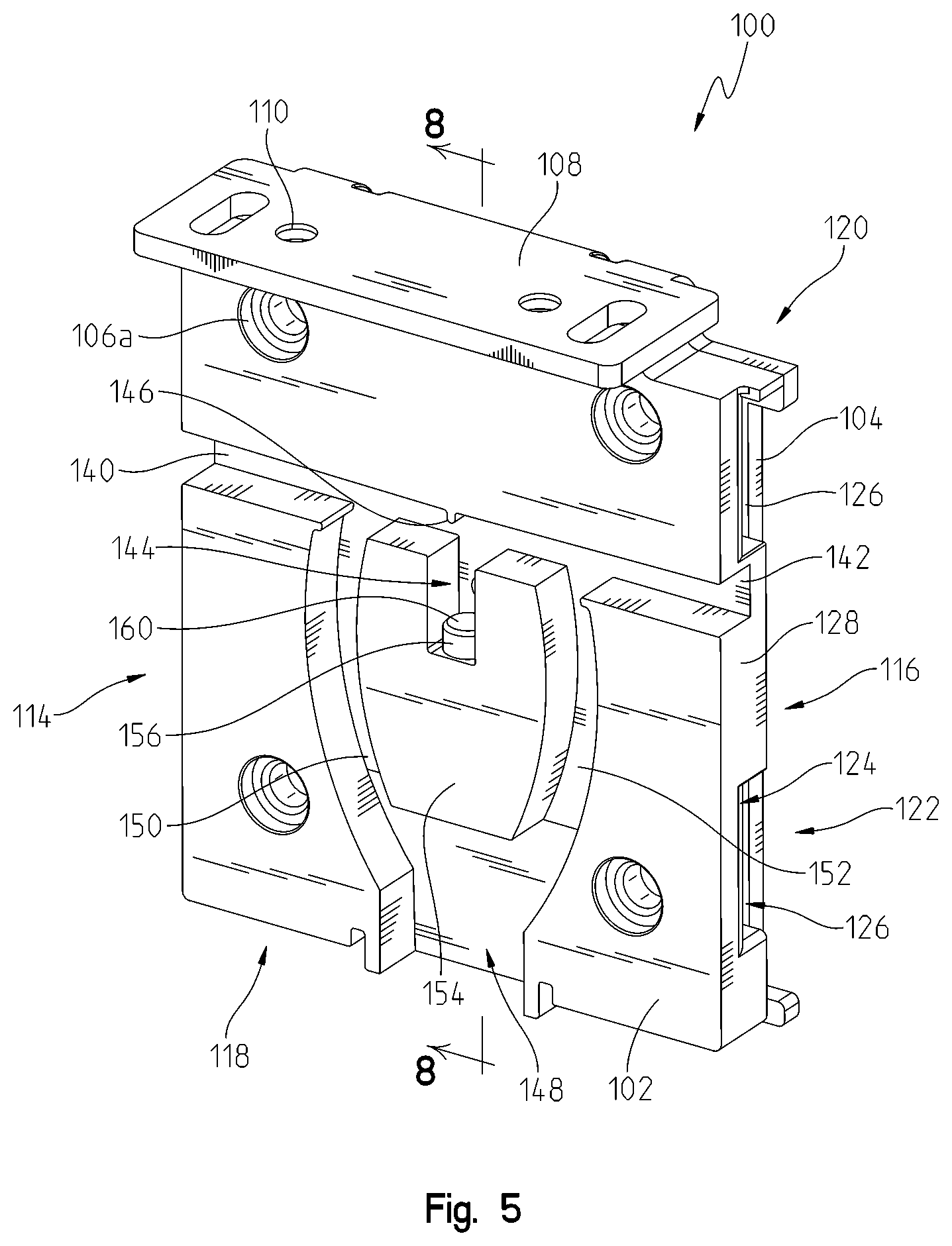
[0013] FIG. 5 is a front perspective view of a second housing assembly configured to receive a portion of a roller tube supported by the roller clutch assembly of FIG. 1;
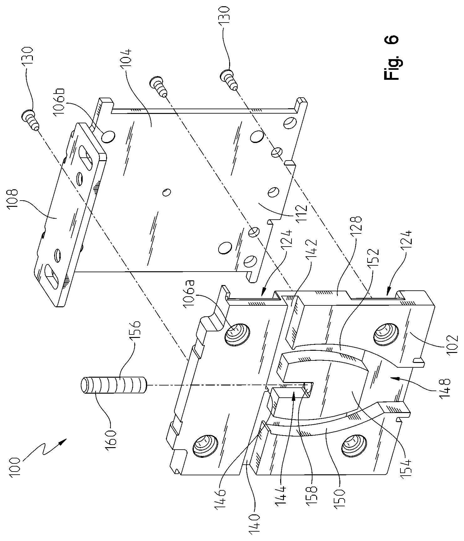
[0014] FIG. 6 is a front exploded view of the second housing assembly of FIG. 5;
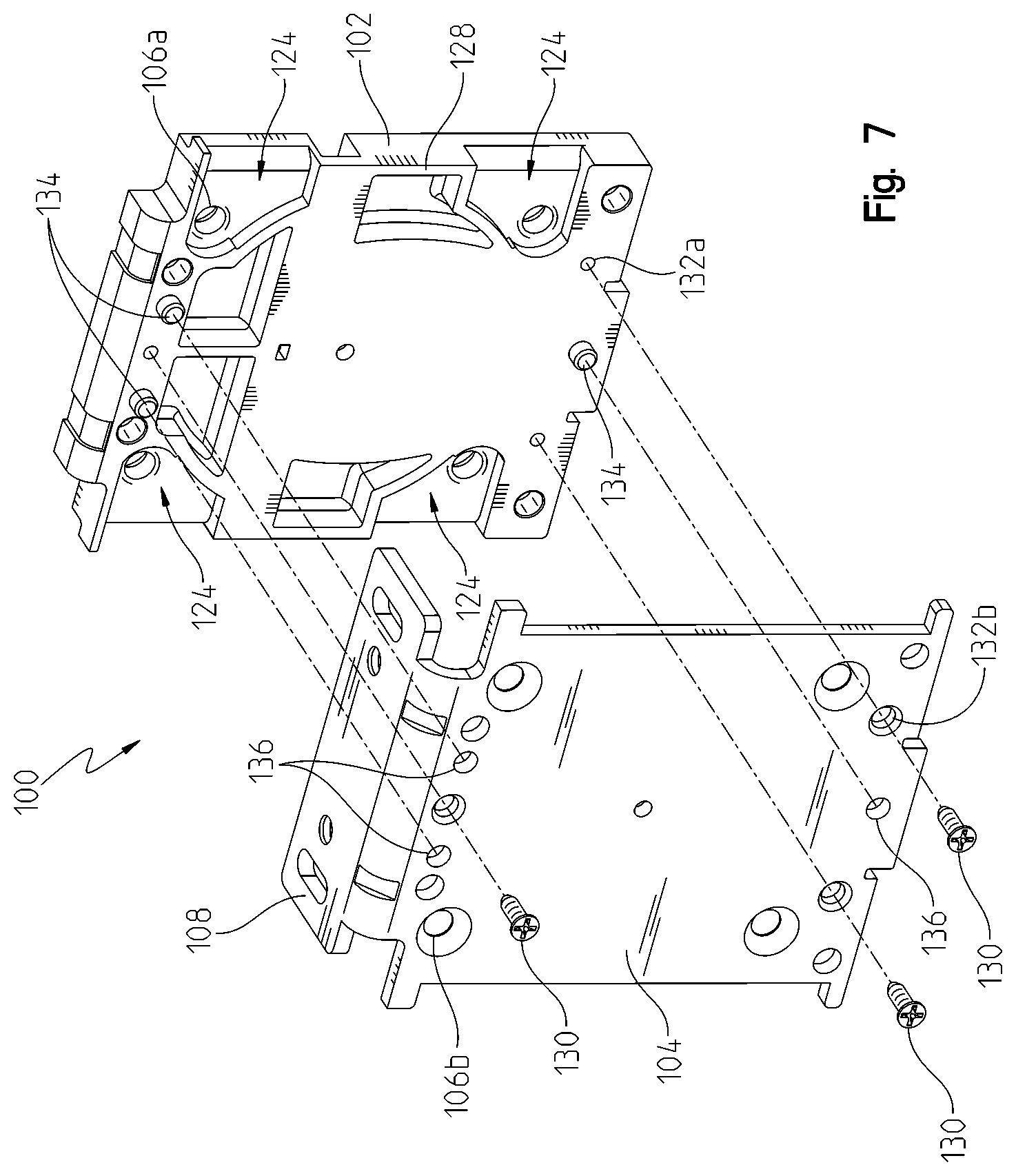
[0015] FIG. 7 is a rear exploded view of the second housing assembly of FIG. 5;
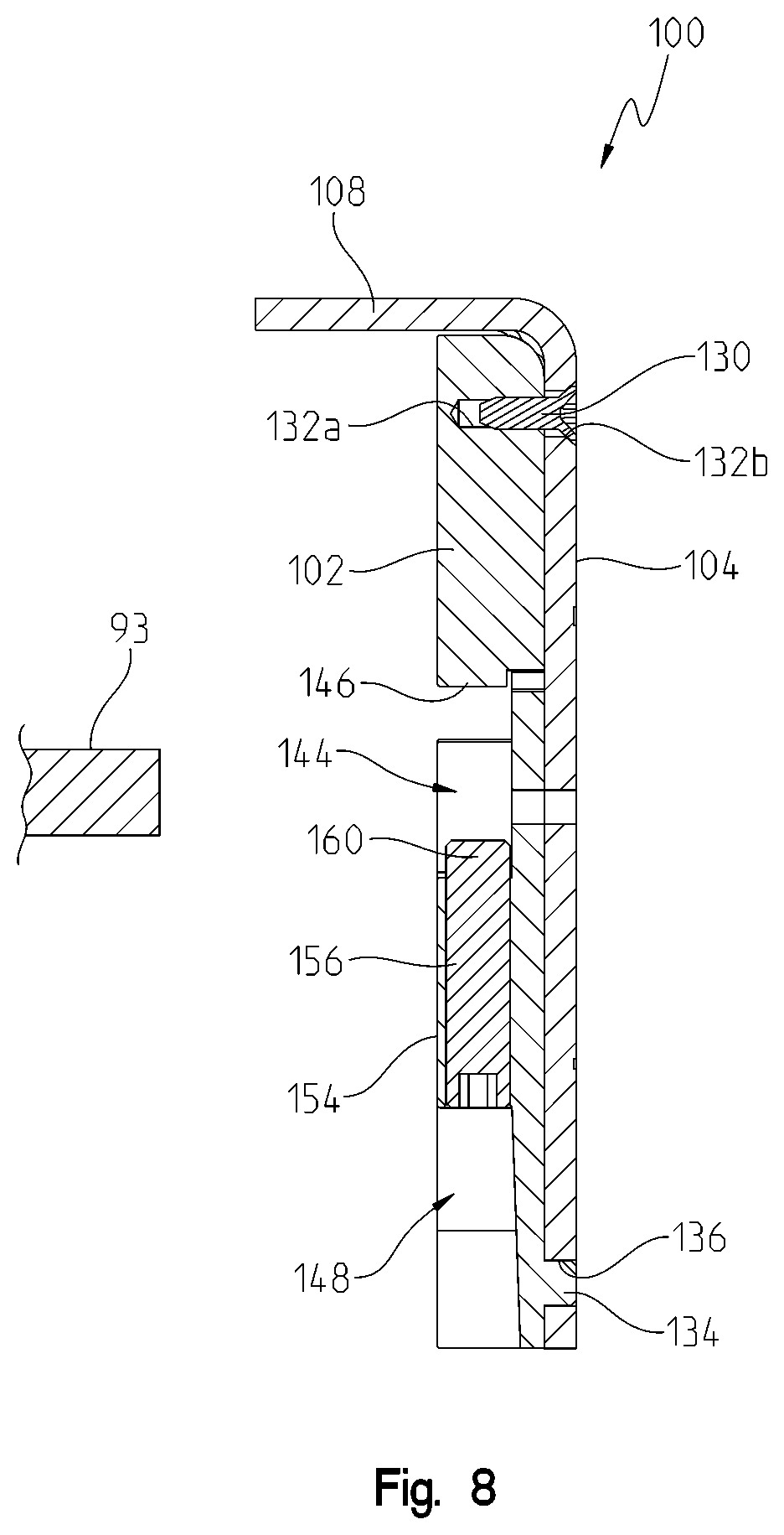
[0016] FIG. 8 is a cross-sectional view of the second housing assembly of FIG. 5, taken along line 8-8 of FIG. 5;
[0017] FIG. 9 is a front perspective view of the housing and roller clutch assemblies of FIG. 1, where the housing assembly is coupled with a removable bracket on a first lateral side;
[0018] FIG. 10 is a front exploded view of the housing and roller clutch assemblies of FIG. 9;
[0019] FIG. 11 is a cross-sectional view of the housing and roller clutch assemblies of FIG. 9, taken along line 11-11 of FIG. 9;
[0020] FIG. 12 is a front perspective view of the housing and roller clutch assemblies of FIG. 9, which is coupled to the removable bracket on the opposing lateral side thereof;
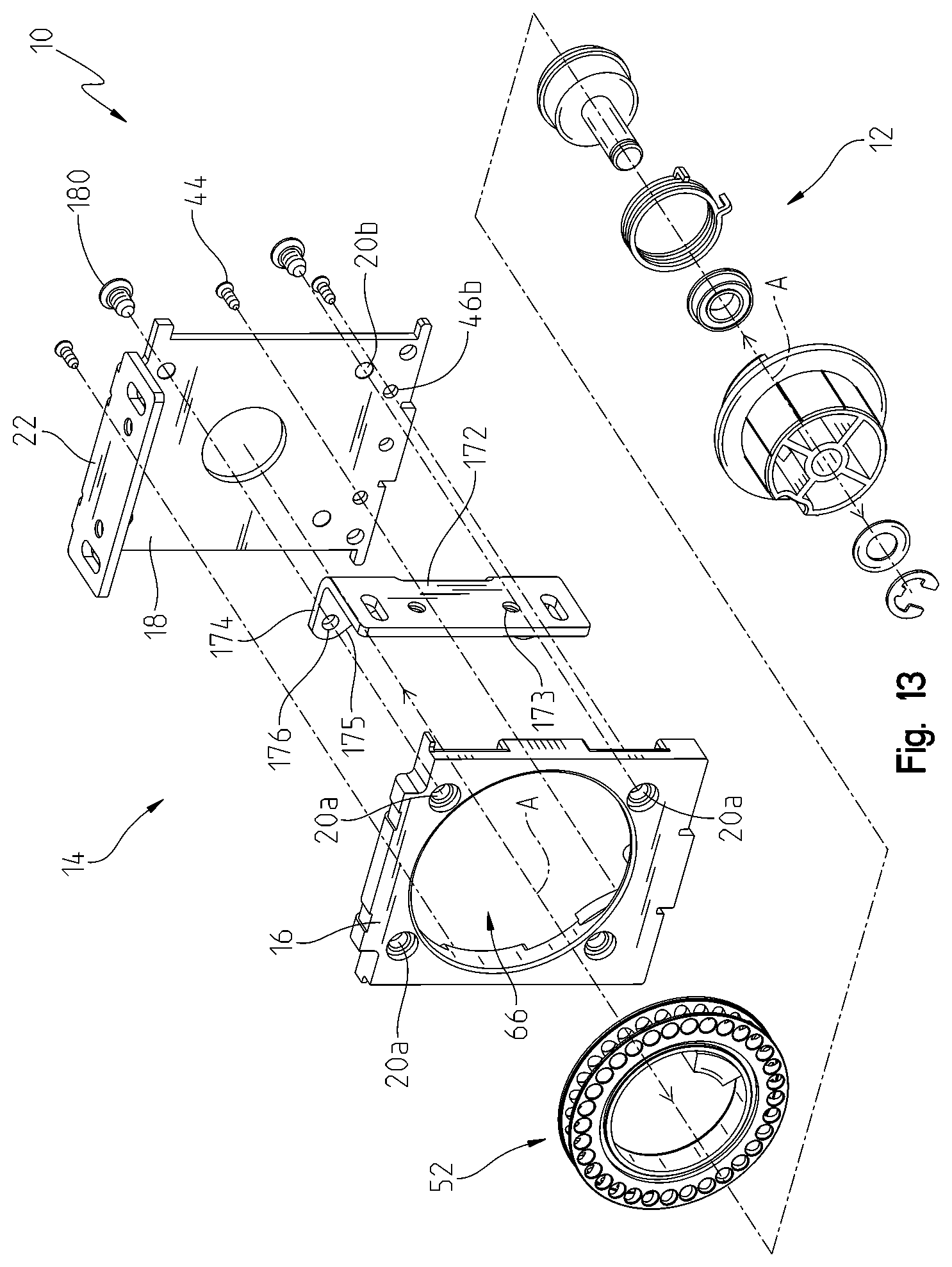
[0021] FIG. 13 is a front exploded view of the housing and roller clutch assemblies of FIG. 12;
[0022] FIG. 14 is a cross-sectional view of the housing and roller clutch assemblies of FIG. 12, taken along line 14-14 of FIG. 12;
[0023] FIG. 15 is a front perspective view of the second housing assembly of FIG. 5 coupled with the removable bracket on a first lateral side;
[0024] FIG. 16 is a front exploded view of the second housing assembly of FIG. 15;
[0025] FIG. 17 is a cross-sectional view of the second housing assembly of FIG. 15, taken along line 17-17 of FIG. 15;
[0026] FIG. 18 is a front perspective view of the second housing assembly of FIG. 5 coupled with the removable bracket on the opposing lateral side thereof;
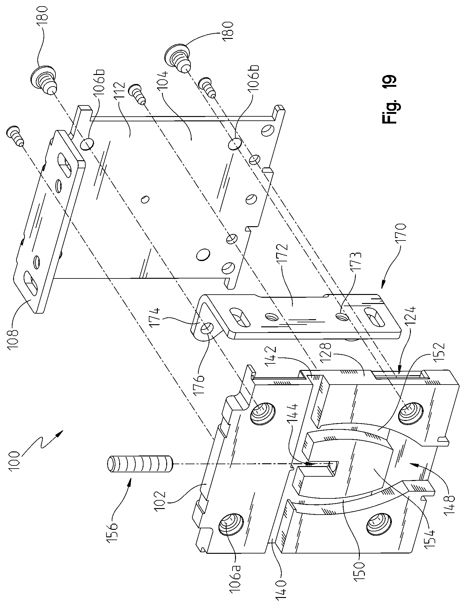
[0027] FIG. 19 is a front exploded view of the second housing assembly of FIG. 18;
[0028] FIG. 20 is a cross-sectional view of the second housing assembly of FIG. 18, taken along line 20-20 of FIG. 18;
[0029] FIG. 21 is a front perspective view of multiple housing and roller clutch assemblies of FIG. 1 coupled together;
[0030] FIG. 22 is a front exploded view of the housing and roller clutch assemblies of FIG. 21;
[0031] FIG. 23 is a front view of the housing and roller clutch assemblies of FIG. 21, with outer covers removed to expose a mounting bracket;
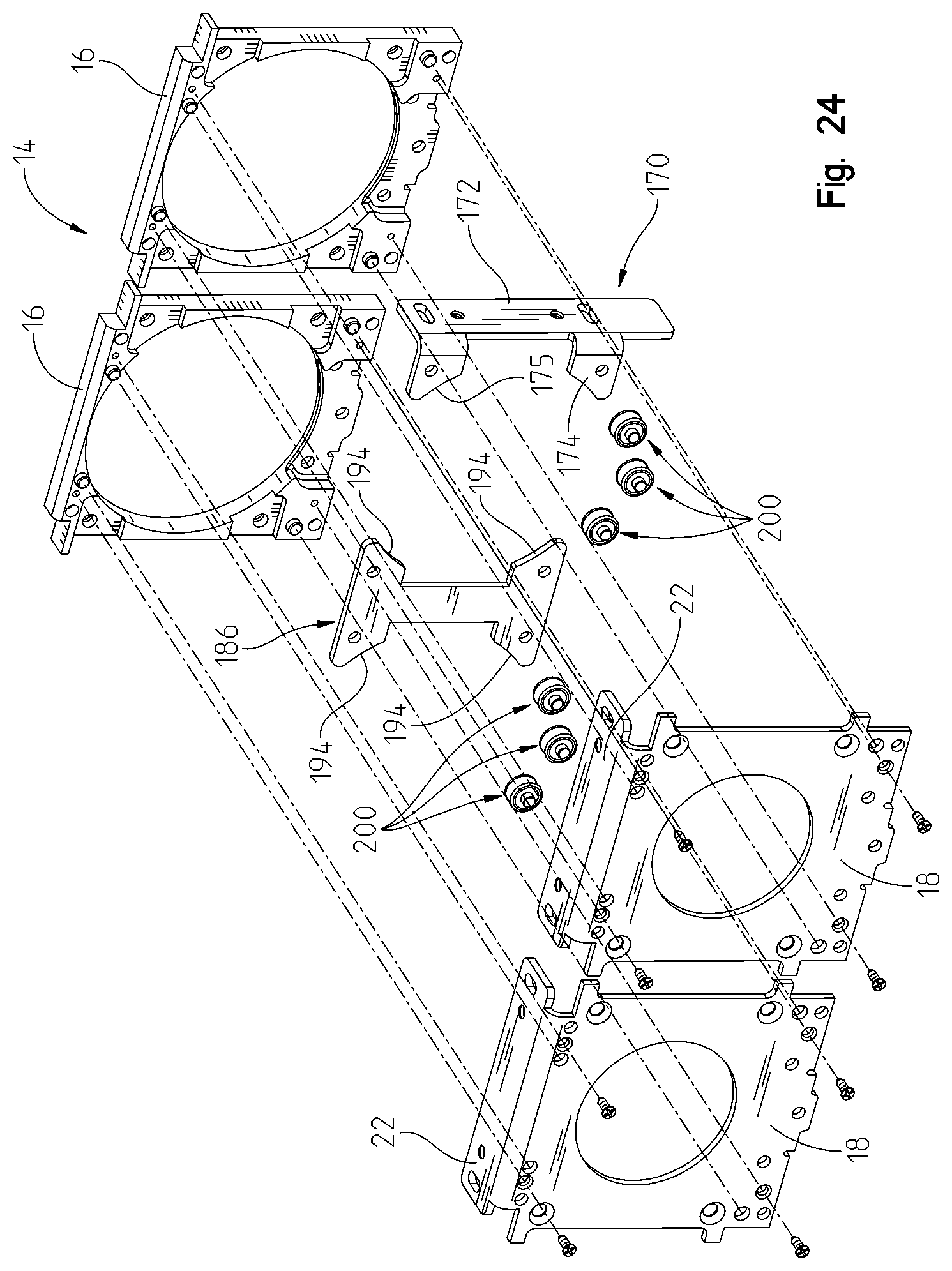
[0032] FIG. 24 is a rear exploded view of housing assemblies of FIG. 21;
[0033] FIG. 25 is a cross-sectional view of the housing and roller clutch assemblies of FIG. 21, taken along line 25-25 of FIG. 21; and
[0034] FIG. 26 is a further cross-sectional view of the housing and roller clutch assemblies of FIG. 21, taken along line 26-26 of FIG. 21.
[0035] Corresponding reference characters indicate corresponding parts throughout the several views. Although the drawings represent embodiments of the present disclosure, the drawings are not necessarily to scale and certain features may be exaggerated in order to better illustrate and explain the present disclosure. The exemplifications set out herein illustrate embodiments of the disclosure, in one form, and such exemplifications are not to be construed as limiting the scope of the disclosure in any manner.
DETAILED DESCRIPTION OF THE DRAWINGS
[0036] Referring to FIGS. 1-4, a roller clutch and housing assembly 10 for a fabric covering includes a roller clutch assembly 12 and a housing assembly 14. Housing assembly 14 includes an outer cover 16 and an inner cover 18 removably coupled together. Housing assembly 14 is configured to be coupled to a wall, window casing, or other similar structure (not shown) by receiving removable fasteners (e.g., screws) through apertures 20 which extend through outer and inner covers 16, 18. Additionally, inner cover 18 includes a fixed bracket portion 22 configured to be removably coupled to a second portion of the wall or window casing. For example, outer and inner covers 16, 18 may receive fasteners through respective apertures 20a, 20b to couple housing assembly 14 to a vertical portion of a window casing while fixed bracket portion 22 may receive fasteners through apertures 24 to couple housing assembly 14 to a horizontal portion of the window casing. Fixed bracket portion 22 may be integrally formed with a main portion 26 of inner cover 18 or may be separate therefrom but fixedly coupled thereto such that fixed bracket portion 22 has a fixed position relative to main portion 26. Housing assembly 14 may be comprised of a rigid material, such as a rigid polymeric and/or metallic material.
[0037] As shown in FIGS. 1-4, housing assembly 14 extends laterally between a first side 28 and a second side 30 and vertically between a third side 32 and a fourth side 34 such that housing assembly 14 generally defines a rectangular shape. Any of sides 28, 30, 32, 34 may include one or more fixed bracket portions 22 and, illustratively, fourth side 34 is integrally formed with fixed bracket portion 22. The distance between first and second sides 28, 30 defines a width W of housing assembly 14, the distance between third and fourth sides 32, 34 defines a height H of housing assembly 14, and a distance between the exterior faces of outer and inner covers 16, 18 defines a depth D of housing assembly 14.
[0038] Additionally, any of sides 28, 30, 32, 34 may be configured to couple with a removable bracket, as disclosed further herein. More particularly, outer and inner covers 16, 18 cooperate with each other when coupled together to form a receiving portion 36 for joining with the removable bracket. Illustratively, as shown in FIGS. 1 and 2, receiving portion 36 is defined by recesses 38 on outer cover 16 which, when outer cover 16 is coupled with inner cover 18, define slots 42. In one embodiment, housing assembly 14 includes two slots 42 along any of sides 28, 30, 32, 34 and slots 42 are spaced apart by a protrusion 40 on outer cover 16 which extends towards inner cover 18. In this way, when outer cover 16 is coupled to inner cover 18, protrusion 40 may contact inner cover 18 while recesses 38 of outer cover 16 are spaced apart therefrom to define slots 42. Slots 42 are configured to receive at least a portion of a removable bracket, as disclosed further hereinafter. In one embodiment, one or more of sides 28, 30, 32, 34 includes a single slot 42.
[0039] As shown in FIG. 3, outer and inner covers 16, 18 are coupled together with removable fasteners 44 (e.g., screws) which are received through openings 46b of inner cover 18 and into openings 46a of outer cover 16. In this way, the head of fasteners 44 is positioned along the innermost surface of inner cover 18 such that they are not visible when housing assembly 14 is mounted to a wall, window casing, or other similar surface. Outer cover 16 also is retained on inner cover 18 using pins 48 projecting from outer cover 16 towards inner cover 18. More particularly, pins 48 are received within openings 50 on inner cover 18. As such, outer and inner covers 16, 18 are coupled together through fasteners 44 and pins 48.
[0040] Referring still to FIGS. 1-4, housing assembly 14 supports clutch assembly 12 thereon, which allows a beaded chain or other similar member to raise and lower a fabric covering 90 (FIG. 4) between a raised position and a lowered position. Fabric covering 90 is wound about a roller tube 91. Clutch assembly 12 also may be configured to maintain the position of fabric covering 90 at a position set by the user. Clutch assembly 12 is configured to rotate about an axis A.
[0041] Referring to FIG. 2, clutch assembly 12 includes a beaded chain wheel 52, a clutch spring driver 54, a drive adapter 56, a spring 58, a guide member 60, a washer 62, and a retention member 64. Beaded chain wheel 52 is supported within an opening 66 of outer cover 16 and is configured to receive at least a portion of drive adapter 56 along an inner radial surface 68. Inner radial surface 68 of beaded chain wheel 52 includes a protrusion 70 extending radially inward therefrom and is configured to engage drive adapter 56 during operation of clutch assembly 12. Further, as known in the art, beaded chain wheel 52 includes a circumferential portion 69 (see FIG. 2) which receives a bead chain 53 (representative portions shown in FIG. 2). Bead chain 53 is guided through channels 71 (see FIG. 3) when clutch assembly 12 is assembled to housing assembly 14.
[0042] Drive adapter 56 includes a support surface 72 which retains drive adapter 56 along inner radial surface 68 of beaded chain wheel 52. Drive adapter 56 also includes a nose 74 which extends outward from support surface 72. Nose 74 includes an internal channel 76 configured to receive a portion of clutch spring driver 54. More particularly, a shaft 78 of clutch spring driver 54 is received through channel 76 when drive adapter 56 and clutch spring driver 54 are coupled together. Clutch spring driver 54 also includes a recessed portion 80 configured to receive spring 58 and a retention portion 82 configured to cooperate with an opening 84 of inner cover 18 for supporting clutch spring driver 54 on inner cover 18. Guide member 60 also is received on shaft 78 of clutch spring driver 54 for aligning and coupling clutch spring driver 54 with drive adapter 56. Shaft 78 extends through nose 74 and clutch spring driver 54 and drive adapter 56 are further coupled together with washer 62 and retention member 64. In one embodiment, retention member 64 is a C-clip frictionally retained within a groove 86 on shaft 78 to prevent axial movement of clutch spring driver 54 relative to drive adapter 56.
[0043] In operation, when a roller 91 (see FIG. 4), which supports fabric covering 90, is coupled to roller clutch and housing assembly 10, one end (e.g., a first or proximal end) of roller 91 receives at least nose 74 of drive adapter 56 of clutch assembly 12 to allow fabric covering 90 to move between the raised and lowered positions and also allow fabric covering 90 to be maintained at a position desired by the user. It may be appreciated that the proximal end of the roller may receive the entirety of nose 74 such that the roller and fabric covering 90 are positioned close to housing assembly 14. In this way, any light gap 92, defined as the distance between fabric covering 90 and housing assembly 14, is minimized, as shown best in FIG. 4.
[0044] To further support the roller and fabric covering 90, a second or idler housing assembly 100 is configured to receive the second or distal end of roller 91. For example, second housing assembly 100 is positioned at an opposing end of a window casing, wall, or similar structure at a distance from housing assembly 14 that allows the roller to be supported on both housings 14, 100. Referring now to FIGS. 5-8, second housing assembly 100 includes an outer cover 102 and an inner cover 104 removably coupled together. Second housing assembly 100 is configured to be coupled to the wall, window casing, or other similar structure (not shown) by receiving removable fasteners (e.g., screws) through apertures 106 which extend through outer and inner covers 102, 104. Additionally, inner cover 104 includes a fixed bracket portion 108 configured to be removably coupled to a second portion of the wall or window casing. For example, outer and inner covers 102, 104 may receive fasteners through respective apertures 106a, 106b to couple second housing assembly 100 to a vertical portion of a window casing while fixed bracket portion 108 may receive fasteners through apertures 110 to couple inner cover 104 to a horizontal portion of the window casing. Fixed bracket portion 108 may be integrally formed with a main portion 112 of inner cover 104 or may be separate therefrom but fixedly coupled thereto. It may be appreciated that fixed bracket portion 108 has a fixed position relative to main portion 112. Second housing assembly 100 may be comprised of a rigid material, such as a rigid polymeric and/or metallic material.
[0045] As shown in FIGS. 5-8, second housing assembly 100 extends laterally between a first side 114 and a second side 116 and vertically between a third side 118 and a fourth side 120 such that second housing assembly 100 generally defines a rectangular shape. Any of sides 114, 116, 118, 120 may include one or more fixed bracket portions 108 and, illustratively, fourth side 120 is integrally formed with fixed bracket portion 108.
[0046] Additionally, any of sides 114, 116, 118, 120 may be configured to couple with a removable bracket, as disclosed further herein. More particularly, outer and inner covers 102, 104 cooperate with each other when coupled together to form a receiving portion 122 for joining with the removable bracket. Illustratively, as shown in FIGS. 5-7, receiving portion 122 is defined by recesses 124 on outer cover 102 which, when outer cover 102 is coupled with inner cover 104, define slots 126. In one embodiment, second housing assembly 100 includes two slots 126 along any of sides 114, 116, 118, 120 and slots 126 are spaced apart by a protrusion 128 on outer cover 102 which extends towards inner cover 104. In this way, when outer cover 102 is coupled to inner cover 104, protrusion 128 may contact inner cover 104 while recesses 124 of outer cover 102 are spaced apart therefrom to define slots 126. Slots 126 are configured to receive at least a portion of a removable bracket, as disclosed further hereinafter. In one embodiment, one or more of sides 114, 116, 118, 120 includes a single slot 126.
[0047] As shown in FIGS. 7 and 8, outer and inner covers 102, 104 are coupled together with removable fasteners 130 (e.g., screws) which are received through openings 132b of inner cover 104 and into openings 132a of outer cover 102. In this way, the head of fasteners 130 is positioned along the innermost surface of inner cover 104 such that they are not visible when second housing assembly 100 is mounted to a wall, window casing, or other similar surface. Outer cover 102 also is retained on inner cover 104 using locators, illustratively pins 134, projecting from outer cover 102 towards inner cover 104. More particularly, pins 134 are received within openings 136 on inner cover 104. As such, outer and inner covers 102, 104 are coupled together through fasteners 130 and pins 134.
[0048] Referring still to FIGS. 5 and 6, outer cover 102 includes a plurality of channels configured to receive the distal end 93 (see FIG. 8, illustratively the distal end is a round pin) of roller 91. Illustratively, outer cover 102 includes a first channel 140 extending inwardly from first side 114 of second housing assembly 100 and a second channel 142 extending inwardly from second side 116 of second housing assembly 100. In this way, the distal end of the roller may be positioned in either of first or second channels 140, 142, depending on the position of second housing 100 relative to the window casing, wall, etc. The distal end of the roller can be positioned at the laterally outer opening of either of channels 140, 142 to move or slide inwardly towards a retention channel 144 configured to maintain the position of the roller thereon. In one embodiment, retention channel 144 extends vertically and generally perpendicularly to first and second channels 140, 142, however, in other embodiments, retention channel 144 may have a different orientation or configuration. Once the distal end of the roller slides inwardly towards retention channel 144, the distal end of the roller is positioned over retention channel 144 when the distal end contacts detent 146 (see FIG. 8), which is generally vertically aligned with retention channel 144. Detent 146 allows the user or installer to guide the distal end of the roller towards retention channel 144 even if retention channel 144 is not visible to the user or installer.
[0049] Additionally, and still referring to FIGS. 5 and 6, depending on the position of second housing assembly 100 relative to the window casing, wall, or other structure, it may be necessary to join the distal end of the roller with second housing assembly 100 from third end 118. More particularly, third end 118 may include an opening 148 which feeds into a third channel 150 and a fourth channel 152. In one embodiment, third and fourth channels 150, 152 extend in a generally vertical direction and open into first and second channels 140, 142, respectively. Third and fourth channels 150, 152 are defined by a protrusion or guide member 154, which also defines retention channel 144. Illustratively, guide member 154 is positioned laterally intermediate third and fourth channels 150, 152 and vertically intermediate opening 148 and first and second channels 140, 142.
[0050] If the user or installer chooses to assemble the roller with second housing assembly 100 using opening 148, the distal end of the roller may move through opening 148 and into either third or fourth channel 150, 152 before being received within respective first or second channel 140, 142. Again, once the distal end of the roller moves within first or second channel 140, 142 and contacts detent 146, the distal end can be moved downwardly into retention channel 144 to secure the distal end to second housing assembly 100.
[0051] Once the distal end of the roller is received within retention channel 144, the distal end is supported by a pin 156 positioned within retention channel 144. As shown best in FIG. 6, pin 156 is received within an aperture 158 of guide member 154 and an upper extent 160 of pin 156 is exposed within retention channel 144 while the remainder of pin 156 is concealed by guide member 154. Pin 156 may be removably coupled to, or otherwise support, the distal end of the roller for coupling the roller to second housing assembly 100. In embodiments, pin 156 includes a threaded exterior 155 which is threaded into an aperture 157 of guide member 154 such that a top surface 159 of pin 156 may be raised or lowered relative to guide member 154. An advantage, among others, of this adjustability is to assist in raising or lowering one end of roller 91 to level roller 91 relative to the environment. In other embodiments, pin 156 is not threaded, but is one of a plurality of pins 156 that may be selected for insertion into aperture 157, each of the plurality of pins 156 having a different height.
[0052] Referring to FIGS. 9-14, housing assembly 14 is shown coupled with a removable bracket 170. Illustratively, as shown in FIGS. 9-11, removable bracket 170 may be coupled to housing assembly 14 along first side 28 and/or, as shown in FIGS. 12-14, removable bracket 170 may be coupled to housing assembly 14 along second side 30. Removable bracket 170 may be comprised of a rigid polymeric material and includes a body portion 172 and at least one tab 174. Body portion 172 includes apertures 173 which are configured to receive removable fasteners (e.g., screws) to couple removable bracket 170 and housing assembly 14 to the window casing, wall, or other similar structure.
[0053] In one embodiment, and referring still to FIGS. 9-14, removable bracket 170 includes two tabs 174, each of which includes an aperture 176, and tabs 174 are spaced apart by a distance 178. Illustratively, distance 178 between tabs 174 may be approximately equal to the distance between apertures 173 on body portion 172. Tabs 174 are generally perpendicular to body portion 172 and are configured to be received within slots 42 along first and second sides 28, 30 of housing assembly 14. In this way, tabs 174 are generally parallel to outer and inner covers 16, 18 and, when removable bracket 170 is coupled to housing assembly 14, body portion 172 is positioned generally perpendicularly to outer and inner covers 16, 18.
[0054] Additionally, and as shown best in FIGS. 10 and 13, tabs 174 are configured to generally straddle a portion of clutch assembly 12. More particularly, the upper tab 174 of removable bracket 170 aligns with the upper apertures 20a, 20b of outer and inner covers 16, 18, respectively, while the lower tab 174 of removable bracket 170 aligns with the lower apertures 20a, 20b, of outer and inner covers 16, 18, respectively. Opening 66 of outer cover 16, which is configured to receive a portion of clutch assembly 12, at least partially extends between the upper and lower apertures 20a on outer cover 16 such that a portion of clutch assembly 12 is vertically aligned with and vertically intermediate apertures 20a. Further, a portion of clutch assembly 12 is positioned between apertures 20 and one of a side of housing assembly 14. In this way, tabs 174 are positioned at least partially above and at least partially below a portion of clutch assembly 12 but do not interfere with clutch assembly 12 when removable bracket 170 is coupled to housing assembly 14. Tabs 174 also are laterally and vertically offset from axis A of clutch assembly 12 such that tabs 174 are not aligned with axis A. Illustratively, tabs 174 may have a curved surface 175 which generally follows the circular shape of opening 66 and beaded chain wheel 52 to allow tabs 174 to couple with housing assembly 14 without interference to clutch assembly 12.
[0055] Removable bracket 170 is removably coupled to housing assembly 14 with removable fasteners 180 (e.g., screws) which are received through apertures 20b of inner cover 18, through apertures 176 of tabs 174, and terminate within a portion of apertures 20a of outer cover 16. In this way, one set of fasteners 180 may be used to couple together outer and inner covers 16, 18 of housing assembly 14 and simultaneously couple removable bracket 170 to housing assembly 14. To couple housing assembly 14 and removable bracket 170 with the window casing, wall, or other structure, fasteners 180 couple removable bracket 170 along one side of housing 14, leaving at least two of apertures 20 available for receiving additional fasteners configured to couple housing assembly 14 to the casing or wall. Additionally, fasteners are received through apertures 173 of removable bracket 170 for coupling to the wall or casing.
[0056] Referring to FIGS. 15-20, second housing assembly 100 also is configured to couple with removable bracket 170 along either of first or second sides 114, 116. Illustratively, as shown in FIGS. 15-17, removable bracket 170 may be coupled to second housing assembly 100 along first side 114 and/or, as shown in FIGS. 18-20, removable bracket 170 may be coupled to second housing assembly 100 along second side 116. More particularly, removable bracket 170 is removably coupled to second housing assembly 100 with removable fasteners 180 (e.g., screws) which are received through apertures 106b of inner cover 104, through apertures 176 of tabs 174, and terminate within a portion of apertures 106a of outer cover 102. In this way, one set of fasteners 180 may be used to couple together outer and inner covers 102, 104 of second housing assembly 100 and simultaneously couple removable bracket 170 to second housing assembly 100. To couple second housing assembly 100 and removable bracket 170 with the window casing, wall, or other structure, fasteners 180 couple removable bracket 170 along one side of second housing assembly 100, leaving at least two of apertures 106 available for receiving additional fasteners configured to couple second housing assembly 100 to the casing or wall. Additionally, fasteners are received through apertures 173 of removable bracket 170 for coupling to the wall or casing.
[0057] By using removable bracket 170 to couple housing assemblies 14, 100 to the window casing, wall, or other similar structure, the user or installer is able to support clutch assembly 12, roller 91, and fabric covering 90 (FIG. 4) on two surfaces because housing assemblies 14, 100 may be coupled to a first surface and removable bracket 170 may be coupled to a second surface. In this way, regardless of the configuration of the wall, window casing, etc., removable bracket 170 can be positioned to either side of housing assemblies 14, 100 for coupling to the wall, window, etc.
[0058] Referring now to FIGS. 21-26, it is possible to couple together multiple housing assemblies 14. In this way, multiple rollers and fabric coverings 90 (FIG. 4) may be positioned in parallel (i.e. axes A of adjacent clutch assemblies 12 are parallel) to accommodate various options for providing covering to a window or wall area. Illustratively, two housing assemblies 14 are aligned such that first side 28 of one of housing assemblies 14 is positioned adjacent second side 30 of the other housing assembly 14. In this configuration, clutch assemblies 12 of housing assemblies 14 are parallel to each other and can accommodate parallel rollers. To maintain alignment of housing assemblies 14, each housing assembly 14 may be coupled to a mounting plate 182 through pins 184 which are received through various openings on inner cover 18. Additionally, mounting plates 182 may be configured to be coupled to a wall, window casing, etc. with removable fasteners (not shown).
[0059] Mounting plates 182 may be coupled together or separate from each other. In one embodiment, housing assemblies 14 may be removably coupled together through mounting plates 182 and/or through a joining member 186. More particularly, when second side 30 of one housing assembly 14 is positioned adjacent first side 28 of the other housing assembly 14, slots 42 of these adjacent housing assemblies 14 face each other. It is these slots 42 which face each other which are configured to receive joining member 186 for aligning and coupling together housing assemblies 14.
[0060] As shown in FIGS. 21-24, joining member 186 generally defines an "I" shape and includes a center portion 188, an upper portion 190, and a lower portion 192. Portions 188, 190, 192 of joining member 186 are integrally formed together and may be comprised of a metallic and/or polymeric material. Upper and lower portions 190, 192 each includes curved surfaces 194, as disclosed further herein, and also each includes apertures 196 for coupling to housing assemblies 14 with removable fasteners received therethrough.
[0061] As shown, upper and lower portions 190, 192 are received within slots 42 of housing assemblies 14 and are configured to generally straddle a portion of clutch assembly 12. Illustratively, curved surfaces 194 of upper and lower portions 190, 192 of joining member 186, are generally complementary to the curve of opening 66 of outer cover 16 and beaded chain wheel 52 such that upper and lower portions 190, 192 are configured to extend around and adjacent a portion of beaded chain wheel 52 and do not interfere with beaded chain wheel 52. In this way, a portion of beaded chain wheel 52 is positioned vertically intermediate upper and lower portions 190, 192.
[0062] Advantages, among others, of using joining member 186, as well as the using of removable bracket(s) 170, is to allow for interchangeability of housing assemblies 14, the reduction in the number of stock components due to removable brackets 170 being coupled to the housing assemblies in different locations, and different mounting configurations for housing assemblies 14. For example, because joining member 186 and removable bracket 170 are removable from housing assembly 14, joining member 186 and/or any number of removable brackets 170 may be coupled with or removed from housing assembly 14 in order to achieve the desired position, orientation, and alignment of the roller and fabric covering 90 (FIG. 4). In this way, housing assemblies 14 may be used to support one or more rollers and fabric coverings 90 (FIG. 4) in various locations and regardless of the orientation and configuration of a window or wall area. Additionally, because tabs 174 of removable bracket 170 and upper and lower portions 190, 192 of joining member 186 are laterally and vertically offset from axis A of clutch assembly 12, removable bracket 170 and joining member 186 do not interfere with any portion of clutch assembly 12.
[0063] Joining member 186 may have any suitable shape to locate a second roller 91 relative to a first roller 91. In the illustrated embodiment, joining member 186 would locate a second roller 91 such that its axis A is generally horizontally aligned with the axis A of a first roller 91. In other embodiments, joining member 186 may locate the second roller 91 relative to first roller 91 such there axes A are vertically offset.
[0064] Referring to FIGS. 23 and 24, in embodiments, housing assembly 14 includes rollers 200 which are captured between outer cover 14 and inner cover 16. Rollers 200 assist in guiding the bead chain 53 of clutch assembly 12 and in reducing resistance to the movement of the bead chain 53 of clutch assembly 12.
[0065] While various embodiments of the disclosure have been shown and described, it is understood that these embodiments are not limited thereto. The embodiments may be changed, modified and further applied by those skilled in the art. Therefore, these embodiments are not limited to the detail shown and described previously, but also include all such changes and modifications.
* * * * *
D00000
D00001
D00002
D00003
D00004
D00005
D00006
D00007
D00008
D00009
D00010
D00011
D00012

D00013
D00014

D00015

D00016

D00017

D00018

D00019
D00020

D00021

D00022

D00023

D00024
D00025

D00026

XML
uspto.report is an independent third-party trademark research tool that is not affiliated, endorsed, or sponsored by the United States Patent and Trademark Office (USPTO) or any other governmental organization. The information provided by uspto.report is based on publicly available data at the time of writing and is intended for informational purposes only.
While we strive to provide accurate and up-to-date information, we do not guarantee the accuracy, completeness, reliability, or suitability of the information displayed on this site. The use of this site is at your own risk. Any reliance you place on such information is therefore strictly at your own risk.
All official trademark data, including owner information, should be verified by visiting the official USPTO website at www.uspto.gov. This site is not intended to replace professional legal advice and should not be used as a substitute for consulting with a legal professional who is knowledgeable about trademark law.