Method and Device for Ascertaining Required Construction Material
Kind Code
U.S. patent application number 15/776262 was filed with the patent office on 2020-08-06 for method and device for ascertaining required construction material. This patent application is currently assigned to EOS GmbH Electro Optical Systems. The applicant listed for this patent is EOS GmbH Electro Optical Systems. Invention is credited to Markus Frohnmaier, Oliver Putz.
| Application Number | 20200247059 15/776262 |
| Document ID | 20200247059 / US20200247059 |
| Family ID | 1000004810237 |
| Filed Date | 2020-08-06 |
| Patent Application | download [pdf] |


| United States Patent Application | 20200247059 |
| Kind Code | A1 |
| Frohnmaier; Markus ; et al. | August 6, 2020 |
Method and Device for Ascertaining Required Construction Material
Abstract
The invention relates to a method for providing required construction material information in the context of producing at least one three-dimensional object using a generative layer construction device, having the following steps: accessing data of a layer to be applied in a first data set in which for each layer to be applied during the production process, it is indicated whether construction material is to be solidified selectively in the layer and if so, at which locations in said layer the construction material is to be solidified; dividing the area of the layer to be applied into sub-regions; assigning weighting factors to the sub-regions, and ascertaining a construction material quantity to be supplied to the coating device in order to apply the layer, wherein the construction material quantity is ascertained using the weighting factors assigned to individual sub-regions and is provided as required construction material information.
| Inventors: | Frohnmaier; Markus; (Hengersberg, DE) ; Putz; Oliver; (Munchen, DE) | ||||||||||
| Applicant: |
|
||||||||||
|---|---|---|---|---|---|---|---|---|---|---|---|
| Assignee: | EOS GmbH Electro Optical
Systems Krailling OT |
||||||||||
| Family ID: | 1000004810237 | ||||||||||
| Appl. No.: | 15/776262 | ||||||||||
| Filed: | November 25, 2016 | ||||||||||
| PCT Filed: | November 25, 2016 | ||||||||||
| PCT NO: | PCT/EP2016/078814 | ||||||||||
| 371 Date: | May 15, 2018 |
| Current U.S. Class: | 1/1 |
| Current CPC Class: | B22F 2003/1057 20130101; B33Y 10/00 20141201; B33Y 30/00 20141201; B33Y 50/02 20141201; B29C 64/393 20170801; B22F 3/1055 20130101; B29C 64/153 20170801 |
| International Class: | B29C 64/393 20060101 B29C064/393; B29C 64/153 20060101 B29C064/153; B22F 3/105 20060101 B22F003/105; B33Y 10/00 20060101 B33Y010/00; B33Y 30/00 20060101 B33Y030/00; B33Y 50/02 20060101 B33Y050/02 |
Foreign Application Data
| Date | Code | Application Number |
|---|---|---|
| Nov 30, 2015 | DE | 10 2015 223 719.2 |
Claims
1. A method of providing a building material consumption information in the context of a manufacturing of at least one three-dimensional object by means of a layer-wise additive manufacturing device, wherein in the layer-wise additive manufacturing device the at least one object is manufactured layer by layer by applying a layer of a building material in powder form layer-wise on a support or an already existing layer of the building material by means of a recoater and by solidifying the building material in parts by a supply of heat to those positions of the layer that correspond to the cross-section of an object by selectively scanning the layer with energy radiation, wherein the method comprises at least the following steps: a step of accessing data of a layer to be applied in a first dataset, in which first dataset for each layer to be applied during the manufacturing it is indicated, whether in such layer there shall be a selective solidification of building material and, if that is the case, at which positions in such layer building material shall be solidified, a step of dividing the area of the layer to be applied into subareas, a step of assigning weighting factors to the subareas, a step of specifying an amount of building material to be supplied to the recoater for the application of the layer, wherein the amount of building material is determined based on the weighting factors assigned to the individual subareas and is provided as building material consumption information.
2. The method according to claim 1, in which the amount of building material is specified depending on a sum of the weighting factors of all subareas.
3. The method according to claim 1, in which the subareas cover the area of the layer to be applied by forming an array of rows and columns.
4. The method according to claim lone of the preceding claims, in which the weighting factors assigned to the subareas are assigned such that they are monotonically increasing, in the direction of movement of the recoater.
5. The method according to claim 1, in which the positions and shapes of regions to be solidified in at least one previous layer are determined and in case in at least one previous layer, there exists a solidified region, those subareas of the layer to be applied that are located at least partially above of a solidified region are assigned a higher weighting factor as compared to the case, in which a subarea is not located at least partially above of a solidified region.
6. The method according to claim 5, in which the subareas are arranged such that the area of the layer to be applied is divided into rows running in parallel to the direction of movement of the recoater and columns running orthogonally thereto, wherein in each row the sum of the weighting factors of all subareas in that row is calculated and afterwards the row having the maximum sum is determined, wherein all subareas in a column are assigned a value of the weighting factor of such subarea in this column that lies in the row having the maximum sum.
7. The method according to claim, in which the positions and shapes of solidified regions in at least one previous layer are simulated with respect to a state after a solidification thereof by means of energy radiation, wherein for the assignment of weighting factors to subareas it is taken into consideration, whether a subarea lies at least partially above of a solidified region provided by the simulation.
8. The method according to claim 7, in which in the simulation of positions and shapes of solidified regions in at least one previous layer, an image of a solidified region is computed referring to a state after a solidification of such region.
9. The method according to claim 1, in which the subareas are stripes running in parallel to the direction of movement of the recoater across the whole layer to be applied.
10. The method according to claims 1, in which in the assignment of values of weighting factors to the subareas the type of building material that is used is taken into consideration.
11. A method of providing a control command set for the manufacturing of at least one three-dimensional object by means of a layer-wise additive manufacturing device, wherein in the layer-wise additive manufacturing device the at least one object is manufactured layer by layer by applying a layer of a building material in powder form layer-wise on a support or an already existing layer of the building material by means of a recoater and by solidifying the building material in parts by a supply of heat to those positions of the layer that correspond to the cross-section of an object by selectively scanning the layer with energy radiation, wherein the method comprises at least the following steps: providing the building material consumption information by means of a method according to claim 1, generating the control command set for the layer-wise additive manufacturing device, wherein in the control command set for at least one layer to be applied the amount of powder to be supplied to the recoater for the application of this layer is specified.
12. A method of manufacturing at least one three-dimensional object by means of a layer-wise additive manufacturing device that is controlled by a control command set generated by means of a method according to claim 11, wherein in the layer-wise additive manufacturing device the at least one object is manufactured layer by layer by applying a layer of a building material in powder form layer-wise on a support or an already existing layer of the building material by means of a recoater and by solidifying the building material in parts by a supply of heat to those positions of the layer that correspond to the cross-section of an object by selectively scanning the layer with energy radiation and the method comprises at least the following steps: a powder application step of providing a layer of a building material in powder form on a support or an already existing layer of the building material in powder form, a solidification step of solidifying the applied layer by means of electromagnetic radiation or particle radiation, in which solidification step the radiation acts on all positions of the layer to be solidified, so that the powder grains at these positions are partially or completely melted by the heat energy introduced by the radiation, so that after a cooling they exist connected to each other as solid state body, wherein the powder application step and the solidification step are successively repeated until all cross-sections of the at least one three-dimensional object to be manufactured are solidified.
13. A provision unit for providing a building material consumption information in the context of a manufacturing of at least one three-dimensional object by means of a layer-wise additive manufacturing device, wherein in the layer-wise additive manufacturing device the at least one object is manufactured layer by layer by applying a layer of a building material in powder form layer-wise on a support or an already existing layer of the building material by means of a recoater and by solidifying the building material in parts by a supply of heat to those positions of the layer that correspond to the cross-section of an object by selectively scanning the layer with energy radiation, wherein the provision unit comprises at least: an access unit designed to access the data of a layer to be applied in a first dataset, in which first dataset for each layer to be applied during the manufacturing it is indicated, whether in such layer there shall be a selective solidification of building material and, if that is the case, at which positions in such layer building material shall be solidified, a division unit, which in operation divides the area of the layer to be applied into subareas, an assignment unit, which in operation assigns weighting factors to the subareas, a specification unit for specifying an amount of building material to be supplied to the recoater for the application of the layer, wherein the provision unit is designed to determine the amount of building material based on the weighting factors assigned to the individual subareas and to provide the same as building material consumption information.
14. A layer-wise additive manufacturing device for manufacturing at least one three-dimensional object from a building material in powder form layer by layer by applying a layer of a building material in powder form layer-wise on a support or an already existing layer of the building material by means of a recoater and by solidifying the building material in parts by a supply of heat to those positions of the layer that correspond to the cross-section of an object by selectively scanning the layer with energy radiation, wherein the device comprises: a support for supporting the object to be formed; a recoater for applying a layer of the building material in powder form on the surface of the support or an already existing layer, an irradiation device that emits electromagnetic radiation or particle radiation and is able to irradiate all positions to be solidified in a layer such that the powder grains at these positions are melted partially or completely by the heat energy introduced by means of the radiation, so that after a cooling the powder grains at these positions exist connected to each other as solid state body, wherein the layer-wise additive manufacturing device comprises and/or is connected to a provision unit according to claim 13 in terms of signaling.
15. Computer program that is able to be loaded into a provision unit and has program code means for carrying out all steps of a method according to claim 1, when the computer program is executed in the provision unit.
Description
[0001] The present invention refers to a method and a provision unit for providing a building material consumption information in the context of a manufacturing of at least one three-dimensional object by means of a layer-wise additive manufacturing device as well as to a method of providing a control command set for a layer-wise additive manufacturing device, which control command set is generated taking into consideration the building material consumption information, as well as to a layer-wise additive manufacturing device and a respective method for manufacturing at least one three-dimensional object by means of a layer-wise additive manufacturing device. In particular, the present invention refers to devices and methods, in which the building material is in powder form.
[0002] DE 10 2011 121 568 A1 describes a layer-wise additive manufacturing method, in which a metal material in powder form is selectively solidified by means of electromagnetic radiation or electron radiation. In the process, a layer of building material is applied onto a support movable in height within a building chamber and is selectively solidified. This process is continued by repetitively applying and solidifying layers until the three-dimensional object has been completed by a selective solidification of the layers stacked upon each other.
[0003] In particular, DE 10 2011 121 568 A1 deals with the problem that the powder usually is always applied on the whole area of the existing building chamber. On the one hand, this leads to a prolonged manufacturing time as a large-area layer is applied, even if only a small fraction of this layer is actually solidified. Furthermore, there is also the disadvantage that large amounts of powder are consumed though only a fraction of the powder is actually solidified.
[0004] A high powder consumption is disadvantageous out of several reasons. Disregarding the higher building material costs that will result, there is also the disadvantage that further resources such as the powder handling systems (sieves, feed systems) will be subjected to an increased wear due to more frequent usage. In particular, when very high objects are built, the time for completion may be prolonged due to powder re-filling processes that become necessary. In an extreme case the total height of the object to be manufactured is limited, if a powder re-filling process is inappropriate. A re-use of non-solidified powder that has already been used in a device for a layerwise additive manufacturing has the disadvantage that the powder deteriorates in the device.
[0005] In order to solve the mentioned problems, DE 10 2011 121 568 A1 suggests constructing within the building chamber a building cell that tightly surrounds the object to be built. In particular, the building cell wall is successively built from the building material used for the building process by a selective solidification. This makes it possible to vary the position of the building cell wall from layer to layer and to adapt the position of the building cell wall to the respective object cross-section in a layer.
[0006] Even though the method described in DE 10 2011 121 568 A1 may definitely lead to a powder saving, the presence of additional walls of solidified building material leads to the result that the unpacking process for the completed objects (removing from the objects non-solidified powder surrounding the same) is impeded. Therefore, the object of the present invention is to provide a method and a device that allow for an alternative optimization of the powder dosage.
[0007] The object is achieved by a method according to claim 1 and claim 11, respectively, a method of manufacturing at least one three-dimensional object by means of a layerwise additive manufacturing device according to claim 12, a provision unit for providing a building material consumption information according to claim 13, a layerwise additive manufacturing device according to claim 14 and a computer program according to claim 15. Further developments of the invention are described in the dependent claims. Here, the methods and the computer program may also be developed further by features of the devices mentioned below and in the dependent claims, respectively.
[0008] According to the invention a method of providing a building material consumption information in the context of a manufacturing of at least one three-dimensional object by means of a layer-wise additive manufacturing device is provided. In the layer-wise additive manufacturing device the at least one object is manufactured layer by layer by applying a layer of a building material in powder form layer-wise on a support or an already existing layer of the building material by means of a recoater and by solidifying the building material in parts by a supply of heat to those positions of the layer that correspond to the cross-section of an object by selectively scanning the layer with energy radiation. The method according to the invention comprises at least the following steps: [0009] a step of accessing data of a layer to be applied in a first dataset, in which first dataset for each layer to be applied during the manufacturing it is indicated, whether in such layer there shall be a selective solidification of building material and, if that is the case, at which positions in such layer building material shall be solidified, a step of dividing the area of the layer to be applied into subareas, a step of assigning weighting factors to the subareas and a step of specifying an amount of building material to be supplied to the recoater for the application of the layer. in particular, the amount of building material is determined based on the weighting factors assigned to the individual subareas and is provided as building material consumption information.
[0010] By the method according to the invention it is taken into account that the building material requirements may be different at different positions: For example, if the building field that is laterally defined by the building chamber and the process chamber, respectively, is circular, however, the recoater moving across the building field is rectangular, at the margin of the building field, meaning where the building field across which the recoater moves has a small extent in the direction of movement of the recoater, there will be needed less building material than in the center. Here, the approach according to the invention can precisely determine the building material requirements particularly in those cases, in which the amount of building material is tightly rated, so that the risk of a premature depletion of the building material during the layer application is counteracted. Subareas of a layer to be applied over which the center (with respect to a direction perpendicular to the direction of movement of the same) of the recoater passes when a layer is applied, in the mentioned case would be for example assigned a higher weighting factor in order to guarantee that the amount of building material is at least so large that a complete recoating is made possible in these subareas. In contrast, subareas over which the margin (with respect to a direction perpendicular to the direction of movement of the same) of the recoater passes when a layer is applied, would be assigned a lower weighting factor as an insufficient powder layer application would not have such severe effects there.
[0011] The provision of the building material consumption information according to the invention makes it possible to dose the building material for a manufacturing process as economically as possible, which leads to cost savings. Furthermore, if necessary, information on the presumably needed total building material need during the manufacturing process may be provided already before the start of a manufacturing process (the total building material need is determined from the building material need for all layers). Then, by means of this information, if necessary, the objects to be manufactured can be arranged in a different way in the building field or a different shape of the building field may be chosen in order to keep the necessary building material amount for the manufacturing of the desired object as small as possible. After all, the method may provide the building material consumption information already at such an early time that based on this information it could be decided to carry out the building process on a differently dimensioned additive manufacturing device than the one originally scheduled therefore in order to minimize the building material consumption, if necessary. In summary, it can be stated that due to the very precise building material consumption information provided according to the invention, an optimization potential may be achieved that may be used for example by appropriate means with respect to an arrangement and/or a design of the manufactured objects on a building field and/or a design of the building field itself.
[0012] Preferably, the amount of building material is specified depending on a sum of the weighting factors of all subareas. If in such a case the amount of building material to be supplied to a subarea to which the weighting factor 1 is assigned is regarded as standard building material amount, the amount of building material that is needed in total for the application of a layer may be determined in a simple way by a summation of the weighting factors of all subareas and a subsequent multiplication with the standard building material amount. Here, by the individual weighting factors also different sizes of the subareas can be taken into consideration.
[0013] Further preferably, the subareas cover the area of the layer to be applied by forming an array of rows and columns. In such a way differing building material needs parallel to a recoating direction and perpendicular thereto may be taken into consideration in a very simple way. Here, subareas result in the form of cells and (enlarged) pixels, respectively, that are defined by the rows and columns and can be individually weighted with the help of weighting factors.
[0014] Preferably, the weighting factors assigned to the subareas are assigned such that they are monotonically increasing, preferably strictly monotonically increasing, in the direction of movement of the recoater. Here, the inventors have recognized that when the building material in the recoater is running low, this need not happen abruptly but may happen gradually. In other words, a building material supply in the recoater that is running low during a layer application may lead to the situation that the predefined thickness of the applied layer is underrun more and more towards the end of the recoating process. In case an object is positioned in an area of the building field that is traversed at the start of the recoating process, the risk of an insufficient layer application for such an object is lower than in an area of the building field that is recoated only towards the end of the recoating process. Therefore, if an object is positioned in an area of the building field that is recoated only towards the end of the recoating process, for such an object the amount of building material to be stored for a layer application has to be increased. This can be taken into consideration by assigning a higher weighting factor to subareas of the layer over which the recoater passes at a later time during a recoating process.
[0015] In a variation of the method according to the invention the positions and shapes of regions to be solidified in at least one previous layer, preferably the immediately preceding layer, are determined, and in case in at least one previous layer, preferably the immediately preceding layer, there exists a solidified region, those subareas of the layer to be applied that are located at least partially above of a solidified region are assigned a higher weighting factor as compared to the case, in which the subarea is not located at least partially above of a solidified region.
[0016] By this variation of the method according to the invention, when determining the building material need for a layer, it is taken into account that in addition to the necessary amount of building material for the application of a layer with a predefined thickness d an additional amount of building material is needed, which additional amount of building material serves for levelling impressions in the immediately preceding building material layer. Impressions in the immediately preceding building material layer result from a compaction of the building material at the solidified positions in the immediately preceding layer or in layers thereunder. In the approach according to the invention, also the position of a solidified region may be taken into account. Namely, depending on the position of this solidified region the building material need may be different. If for example the solidified region is recoated only towards the end of the recoating process, it is more important to store enough additional building material for this region, so that at this position there is sufficient building material available for the application with the predefined layer thickness.
[0017] In a modification of the just described variation of the method according to the invention the subareas are arranged such that the area of the layer to be applied is divided into rows running in parallel to the direction of movement of the recoater and columns running orthogonally thereto, wherein at first in each row the sum of the weighting factors of all subareas in that row is calculated and afterwards the row having the maximum sum is determined. Afterwards, all subareas in a column are assigned a value of the weighting factor of such subarea in this column that lies in the row having the maximum sum. Thus, in this approach at first the row with the maximum building material need is identified and afterwards the required building material amount is specified under the assumption that also in all other rows this maximum amount would be required. Such an approach will lead to an identified building material need that is slightly too high, however, by such an approach one may guard against unexpected building material losses or unintended building material losses during a layer application.
[0018] In a further modification of the described variation of the method according to the invention the positions and shapes of solidified regions in at least one previous layer, preferably the immediately preceding layer, are simulated with respect to a state after a solidification thereof by means of energy radiation, wherein for the assignment of weighting factors to subareas it is taken into consideration, whether a subarea lies at least partially above of a solidified region provided by the simulation. Such an approach makes a more accurate determination of the building material need possible, as it is taken into account that the extent of a region to be solidified in a layer may deviate from the actual extent of a region after its solidification as a result of the manner of the solidification process. Here, according to the invention in the simulation of the extent of the solidified region also volume reduction occurrences due to the solidification process of the building material may be simulated, if necessary.
[0019] In the simulation of positions and shapes of solidified regions in at least one previous layer, preferably the immediately preceding layer, an image of a solidified region is computed referring to a state after a solidification of such region. thereby, the extent of a solidified region may be determined in a particularly accurate way.
[0020] Preferably, the subareas are stripes running in parallel to the direction of movement of the recoater across the whole layer to be applied. Thereby, the assignment of weighting factors is simplified as a waiting factor is assigned only to each stripe.
[0021] In this way in particular the extent in the recoating direction of the region to be solidified after the layer application and/or the extent in the recoating direction of an already solidified region in previous layers may be taken as a basis for the assignment of the weighting factors.
[0022] Preferably, in the assignment of values of weighting factors to the subareas the type of building material that is used is taken into consideration. The reason is that usually the influence of the position and orientation of already solidified regions or regions still to be solidified after a layer application will be different for different powder materials. According to the just described approach this circumstance is automatically taken into account in the assignment of weighting factors.
[0023] An inventive method of providing a control command set for the manufacturing of at least one three-dimensional object by means of a layer-wise additive manufacturing device, wherein in the layer-wise additive manufacturing device the at least one object is manufactured layer by layer by applying a layer of a building material in powder form layer-wise on a support or an already existing layer of the building material by means of a recoater and by solidifying the building material in parts by a supply of heat to those positions of the layer that correspond to the cross-section of an object by selectively scanning the layer with energy radiation, comprises at least the following steps:
[0024] Apart from the provision of the building material consumption information by means of an inventive method described above, a control command set for the layer-wise additive manufacturing device is generated, wherein in the control command set for at least one, preferably several, especially preferably for each, layer to be applied the amount of powder to be supplied to the recoater for the application of this layer is specified.
[0025] Thus, in the just described method a control command set for a layer-wise additive manufacturing device may be obtained, which automatically and very precisely determines the building material need for the application of a layer and controls the layer-wise additive manufacturing device correspondingly.
[0026] In an inventive method at least one three-dimensional object is manufactured by means of a layer-wise additive manufacturing device that is controlled by a control command set generated by means of a the inventive method, wherein in the layer-wise additive manufacturing device (1) the at least one object is manufactured layer by layer by applying a layer of a building material in powder form layer-wise on a support or an already existing layer of the building material by means of a recoater and by solidifying the building material in parts by a supply of heat to those positions of the layer that correspond to the cross-section of an object by selectively scanning the layer with energy radiation and the method comprises at least the following steps: [0027] a powder application step of providing a layer of a building material in powder form on a support or an already existing layer of the building material in powder form, [0028] a solidification step of solidifying the applied layer by means of electromagnetic radiation or particle radiation, in which solidification step the radiation acts on all positions of the layer to be solidified, so that the powder grains at these positions are partially or completely melted by the heat energy introduced by the radiation, so that after a cooling they exist connected to each other as solid state body, [0029] wherein the powder application step and the solidification step are successively repeated until all cross-sections of the at least one three-dimensional object to be manufactured are solidified. A just described method of manufacturing of objects by means of a layer-wise additive manufacturing device may use the available building material in a particularly effective way. In the end, due to the economical use of the building material the costs for the manufacturing of objects may be lowered.
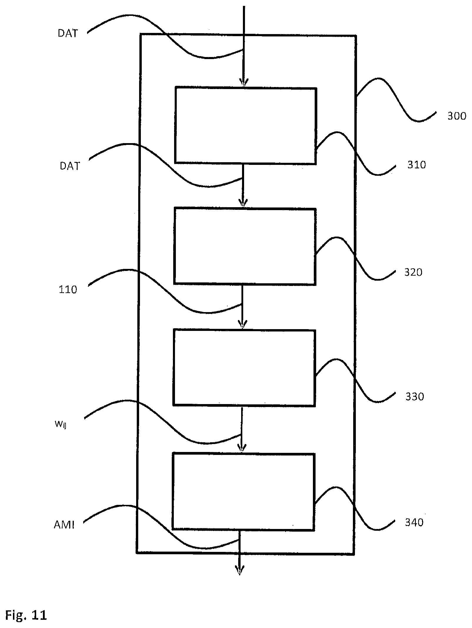
[0030] An inventive provision unit for providing a building material consumption information (AMI) in the context of a manufacturing of at least one three-dimensional object by means of a layer-wise additive manufacturing device, wherein in the layer-wise additive manufacturing device the at least one object is manufactured layer by layer by applying a layer of a building material in powder form layer-wise on a support or an already existing layer of the building material by means of a recoater and by solidifying the building material in parts by a supply of heat to those positions of the layer that correspond to the cross-section of an object by selectively scanning the layer with energy radiation, wherein the provision unit comprises at least: [0031] an access unit designed to access the data of a layer to be applied in a first dataset, in which first dataset for each layer to be applied during the manufacturing it is indicated, whether in such layer there shall be a selective solidification of building material and, if that is the case, at which positions in such layer building material shall be solidified, [0032] a division unit, which in operation divides the area of the layer to be applied into subareas, [0033] an assignment unit, which in operation assigns weighting factors to the subareas, [0034] a specification unit for specifying an amount of building material to be supplied to the recoater for the application of the layer, [0035] wherein the provision unit is designed to determine the amount of building material based on the weighting factors assigned to the individual subareas and to provide the same as building material consumption information.
[0036] The provision unit may be implemented as separate unit, however, it may also be integrated into a layer-wise additive manufacturing device. Interfaces in the provision unit need not necessarily be configured as hardware components. They can also be implemented as software modules, for example when information and data, respectively, need to be passed to a following component of the provision unit and to an external component, respectively, only by means of software. Also, the interfaces may consist of hardware and software components such as a standard hardware interface that is specifically configured by means of software for the particular application. Furthermore, several interfaces may be combined to one common interface such as an input-output interface.
[0037] All in all, a large part of the components for implementing the provision unit in the inventive way, in particular the access unit, the division unit, the assignment unit and the specification unit may be implemented completely or in part in the form of software modules on a processor.
[0038] An inventive provision unit enables the building material need determination remote from a layer-wise additive manufacturing device on which the building process shall run in the end. Thereby, the provision unit can be used for example already at the design stage of objects in order to determine the manufacturing costs of an object, which manufacturing costs depend on the required powder need for a building process.
[0039] An inventive layer-wise additive manufacturing device for manufacturing at least one three-dimensional object from a building material in powder form layer by layer by applying a layer of a building material in powder form layer-wise on a support or an already existing layer of the building material by means of a recoater and by solidifying the building material in parts by a supply of heat to those positions of the layer that correspond to the cross-section of an object by selectively scanning the layer with energy radiation, comprises: [0040] a support for supporting the object to be formed; [0041] a recoater for applying a layer of the building material in powder form on the surface of the support or an already existing layer, [0042] an irradiation device that emits electromagnetic radiation or particle radiation and is able to irradiate all positions to be solidified in a layer such that the powder grains at these positions are melted partially or completely by the heat energy introduced by means of the radiation, so that after a cooling the powder grains at these positions exist connected to each other as solid state body, wherein the layer-wise additive manufacturing device comprises a provision unit according to the invention and/or is connected to a provision unit according to the invention in terms of signalling. Thereby, a layer-wise additive manufacturing device according to the invention makes it possible to carry out manufacturing processes of objects with a particularly effective use of the building material.
[0043] An inventive computer program is able to be loaded into a provision unit and has program code means for carrying out all steps of a method of providing a building material consumption information according to the invention, when the computer program is executed in the provision unit.
[0044] Features and practicalities of the invention will be described in the following by means of embodiments making reference to the drawings, wherein the figures show:
[0045] FIG. 1 is a representation of an example of a layer-wise additive manufacturing device according to the invention,
[0046] FIG. 2 is a cross-sectional view for illustrating the application of a powder layer in a layer-wise additive manufacturing method.
[0047] FIG. 3 shows an exemplary inventive division of the area of a layer to be applied into subareas and the assignment of weighting factors to the subareas.
[0048] FIG. 4 shows a top view of the recoating area in a case, in which the building field has a shape deviating from the recoating region.
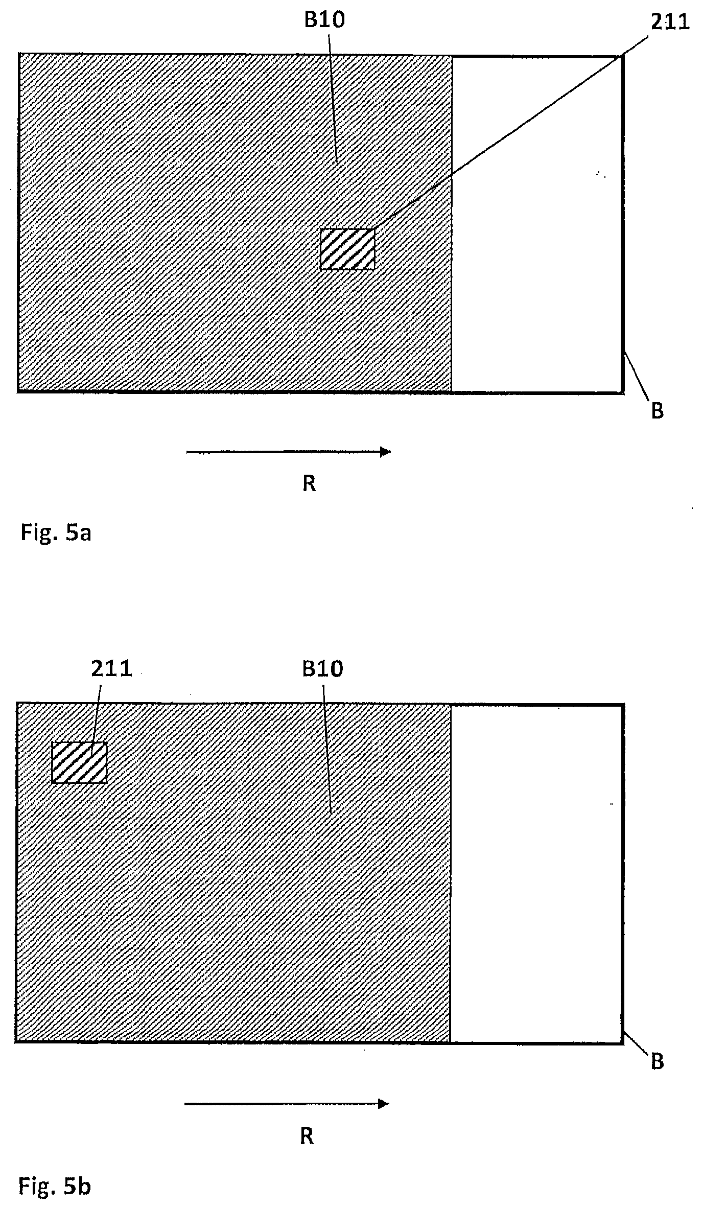
[0049] FIGS. 5a and 5b serve for an explanation of the influence of the position of a cross-section to be solidified in the building field on the powder consumption.
[0050] FIG. 6 shows an exemplary assignment of weighting factors in a building situation represented in FIGS. 5a and 5b.
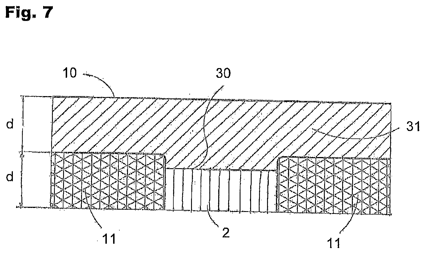
[0051] FIG. 7 is a cross-sectional view for illustrating the influence of solidified regions on the building material need.
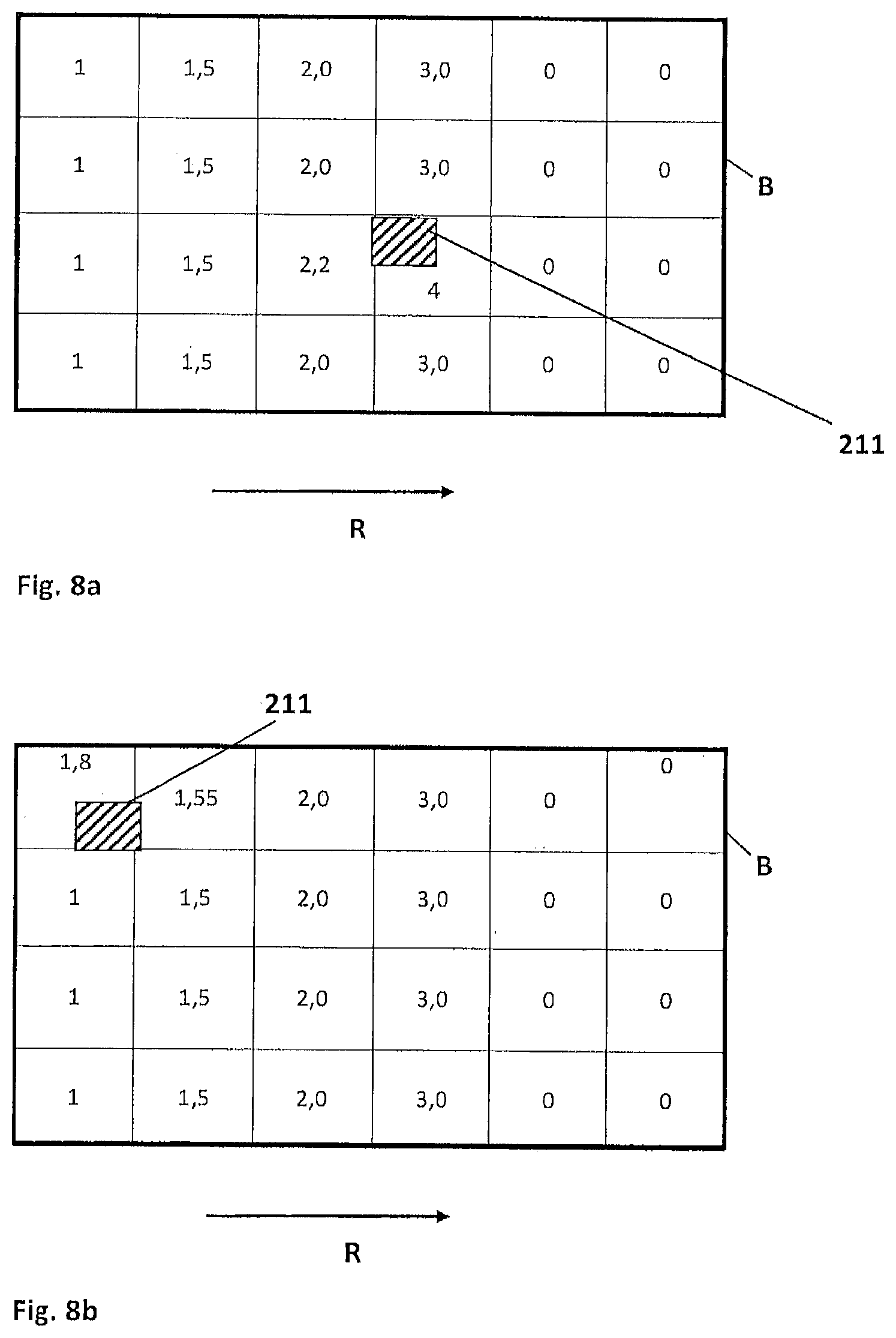
[0052] FIGS. 8a and 8b show an exemplary assignment of weighting factors in a building situation shown in FIGS. 5a and 5b taking additionally into account solidification processes in previous layers.
[0053] FIGS. 9a and 9b show an exemplary assignment of weighting for illustrating the influence of the orientation of an object to be manufactured on the building material need.
[0054] FIG. 10 shows a top view of a cross-section of an object to be manufactured, which cross-section is currently being manufactured in order to illustrate a possible approach for the simulation of the actually solidified region.
[0055] FIG. 11 shows a schematic block diagram for illustrating an embodiment of a provision unit according to the invention.
[0056] In the following, an example of a layerwise additive manufacturing device 1 according to the invention is described with reference to FIG. 1. The device shown in FIG. 1 is a laser sintering or laser melting device 1. In order to build an object 2, the device comprises a process chamber 3 having a chamber wall 4.
[0057] A container 5, which is open to the top and has a wall 6, is arranged in the process chamber 3. A support 7 that is movable in a vertical direction V is arranged in the container 5. A base plate 8 is arranged at the support 7 and forms the bottom end of the container 5 and thereby forms its bottom. The base plate 8 may be a plate formed separately from the support 7, which is attached to the support 7, or it may be formed integrally with the support 7. Depending on the powder and the process that are used, a building platform 9 may be additionally attached on the base plate 8, on which building platform 9 the object 2 is built. However, the object 2 may also be built on the base plate 8 itself, which base plate 8 then serves as building platform. In FIG. 1, the object 2 to be formed on the building platform 9 in the container 5 is shown below a working plane 10 defined by the upper edge of the wall 6 in an intermediate state with several solidified layers that are surrounded by building material 11 that remained unsolidified.
[0058] Furthermore, the laser sintering device 1 comprises a storage container 12 for a building material 13 in powder form that is solidifiable by electromagnetic radiation and a recoater 14 that can be moved in a horizontal direction H for applying the building material 13 on the working plane 10. A work plate 15 that surrounds the container 5 on all sides and is preferably thermally insulated from the container, is arranged such that its upper surface lies within the working plane 10. In the work plate 15 an overflow slit 16 is arranged at the side opposed to the storage container 12. Surplus powder 17 may fall through the overflow slit 16 into an overflow container 18. Furthermore, a radiative heating 19 for heating the building material 13 applied on the working plane 10 is arranged in the process chamber.
[0059] Furthermore, the laser sintering device 1 comprises an exposure device 20 having a laser 21 that generates a laser beam 22, which can be deflected via a deflection device 23 and can be focused by a focusing device 24 through a coupling window 25 arranged in the top side of the wall 4 of the process chamber 3 onto the working plane 10.
[0060] Moreover, the laser sintering device 1 comprises a control unit 29, by which the individual components of the device 1 are controlled in a coordinated way for carrying out the building process. The control unit may comprise a CPU, the operation of which is controlled by a computer program (software). The computer program can be stored separately from the device on a storage medium, from which it can be loaded into the device, in particular into the control unit.
[0061] In operation, at first the support 7 is lowered by an amount that corresponds to the desired layer thickness in order to apply a powder layer. Then, by moving the recoater 14 across the working plane 10, a layer of the building material 13 in powder form is applied. Here, a designated recoating area B is defined as that region of the working plane 10 within which the recoater 14 is able to apply powder in an intended use, thus, in which its recoating function is possible. In the laser sintering device shown in FIG. 1, the designated recoating area B extends from the location at which the recoater 14 takes up building material in powder form from the storage container 12 up to the overflow slit 16 through which the surplus powder 17, which still remained in the recoater 14 at that position, falls into the overflow container 18. Beyond that position there is no recoating function possible.
[0062] The designated recoating area B covers the building field B1, meaning the region of the working plane 10 that lies within the upper opening of the container 5, and a margin region B2 surrounding the building field B1. Here, the building field B1 is the region in which the object 2 can be built and in which the applied and selectively solidified powder layers may be lowered before the application of a new powder layer.
[0063] The applied powder layer is pre-heated by the radiant heating 19 that is designed to heat the whole building field B1. Also a part of the work plate 15 is heated by the radiant heating 19. However, the work plate 15 may in addition also be heated by a dedicated heating element (not shown in the figure) attached to it.
[0064] Subsequently, the cross-section of the object 2 to be manufactured is scanned by the laser beam 22, so that the building material 13 in powder form is solidified at the positions that correspond to the cross-section of the object 2 to be manufactured. These steps are repeated until the object is completed and can be removed from the building space.
[0065] FIG. 2 shows schematically enlarged a detail A, which is surrounded by a dashed line in FIG. 1.
[0066] After the application and solidification of a powder layer 30 the solidified part of the object 2 to be manufactured therein is surrounded by powder 11 that remained unsolidified. Then, by means of a movement of the recoater 14 in a recoating direction R a further powder layer 31 of the building material 13 is applied on this previously applied and selectively solidified powder layer 30.
[0067] As shown in FIG. 2, the recoater 14 comprises a recoating unit having a blade positioned forward facing in the recoating direction R (front blade 14a) and a blade positioned backward facing in the recoating direction B (rear blade 14b). These two blades at least partially delimit an intermediate space 14c in the recoating direction B and in the opposite direction to the recoating direction. This intermediate space 14c defined by the two blades 14a, 14b is designed to accommodate a supply of building material 13 in powder form. Perpendicular to the drawing plane the two blades 14a, 14b and thus also the intermediate space 14c defined by them extend across the whole width of the area to be recoated.
[0068] When moving the recoater 14 in the recoating direction R, a portion of this building material 13 in powder form remains on the immediately preceding layer 30 and is drawn out to a uniform thin powder layer 31 having the thickness d by the rear blade 14b. The applied layer thickness is defined by the difference in height between the lower edge of the rear blade 14b and the previously applied layer 30.
[0069] In order to apply the new powder layer 31, the recoating unit 14a-c of the recoater 14 at first moves to the storage container 12 and takes up there a predetermined amount of the building material 13 in powder form. This predetermined amount of powder is preferably larger than the amount of powder necessary for applying a layer of the building material 13 in powder form. Then, the recoating unit 14a-c moves over the working plane 10 and applies the new powder layer 31. When the recoating unit 14a-c reaches the overflow slit 16, surplus powder 17 having still remained in the recoater 14 falls there into the overflow container 18.
[0070] As already mentioned in the introduction, the costs of a manufacturing process by means of a layerwise additive manufacturing device are affected very much by the amount of building material that must be used for the manufacturing process. in this respect, the inventors have found that the expected material consumption in the manufacturing of one or several objects depends on the position and orientation of the objects in the building space. In order to be able to determine the expected powder need as precisely as possible and be able to take into account the just described dependency of the powder need on the position and orientation of the objects to be manufactured, the inventive method for determining the powder need proceeds as follows:
[0071] Before the application of a layer of a building material in a layerwise additive manufacturing method all information for this layer and the previous layers, meaning in particular the layer thickness and the position, extent and orientation of the regions to be solidified, exist in a dataset.
[0072] In a first approximation, the building material needed for one layer depends on the area of the designated recoating area B as well as on the thickness d of the layer to be newly applied. A compaction of the powder material generated by the layer application, which compaction leads to the fact that powder has to be applied with a larger layer thickness than the intended thickness d, is known to the skilled person and is not explained here in detail. Whether such a compaction by the layer application is taken into account or not has no influence on the applicability of the present invention.
[0073] According to the invention the powder need for a layer is determined more precisely by dividing the area of the layer to be applied, meaning in particular the designated recoating area B, into subareas and assigning weighting factors to these subareas, which weighting factors express the extent of the powder need for a subarea. In the following, the approach is explained by referring to FIG. 3:
[0074] FIG. 3 shows a top view of the designated recoating area B. The recoating direction, meaning the direction in which a recoater 14 moves across the recoating area B for applying a powder layer, is indicated by an arrow R. it can be seen that the recoating area is divided into 4.times.6 subareas 110. A weighting factor w.sub.ij is assigned to each of the subareas 110, which weighting factor embodies the powder need in a powder application in this area. Here, according to the invention it is assumed that there exists a standard powder need per unit area, which standard powder need per unit area can be determined based on the above described first approximation taking into account the layer thickness d and which standard powder need per unit area depends on the building material that is used. For example, a weighting factor having the value 1 could be assigned to a subarea 110 having the size of a unit area. The weighting factors w.sub.ij then could for example be chosen the larger the larger the areas of the respective subareas 110. However, in FIG. 3 such an approach would not yet lead to different weighting factors as the areas of all subareas 110 are chosen to be of the same size.
[0075] Due to the introduction of weighting factors, the powder need for the application of a layer can be determined by summing the weighting factors of all subareas 110 and subsequently multiplying the sum with the standard powder need per unit area. The result obtained then corresponds to the amount of powder needed for the application of the current layer or at least is proportional to the same.
[0076] When assigning weighting factors to the subareas 110, there exist different approaches. Exemplary criteria that may be followed when doing so will be described in the following within the context of different embodiments of the invention. Here, each of the embodiments shall only describe an example for a possible approach. In particular, it is also possible to combine the approaches described in the individual embodiments in order to arrive thereby at (thus possibly more refined, i.e. more accurate) weighting factors that are a consequence of several criteria. Furthermore, specifically shown numerical values for the weighting factors are only examples for explaining the approach. The skilled person may choose other numerical values in a particular case depending on the significance for the building material
* * * * *
D00000
D00001
D00002
D00003
D00004
D00005
D00006
D00007
D00008
D00009
D00010
XML
uspto.report is an independent third-party trademark research tool that is not affiliated, endorsed, or sponsored by the United States Patent and Trademark Office (USPTO) or any other governmental organization. The information provided by uspto.report is based on publicly available data at the time of writing and is intended for informational purposes only.
While we strive to provide accurate and up-to-date information, we do not guarantee the accuracy, completeness, reliability, or suitability of the information displayed on this site. The use of this site is at your own risk. Any reliance you place on such information is therefore strictly at your own risk.
All official trademark data, including owner information, should be verified by visiting the official USPTO website at www.uspto.gov. This site is not intended to replace professional legal advice and should not be used as a substitute for consulting with a legal professional who is knowledgeable about trademark law.