Optic scalpel
Kind Code
U.S. patent application number 16/350933 was filed with the patent office on 2020-08-06 for optic scalpel. The applicant listed for this patent is Joshua Tyson. Invention is credited to Joshua Tyson.
| Application Number | 20200246037 16/350933 |
| Document ID | / |
| Family ID | 1000003879467 |
| Filed Date | 2020-08-06 |


| United States Patent Application | 20200246037 |
| Kind Code | A1 |
| Tyson; Joshua | August 6, 2020 |
Optic scalpel
Abstract
The optic scalpel is a scalpel available in various sizes and shapes that have circular led lights surrounding the base of the knife blade. When activated the lights provide additional lighting for surgical procedures. The optic scalpel optimizes lighting conditions for accurate incisions or dissections. The optic scalpel improves from its predecessor by intergrading led lights with a scalpel. The optic scalpel can be used independently to illuminate a local area for incisions or tissue cutting. The optic scalpel is powered by cell batteries that are located in the handle. The led lights are activated by a switch on the top of the handle.
| Inventors: | Tyson; Joshua; (New York, NY) | ||||||||||
| Applicant: |
|
||||||||||
|---|---|---|---|---|---|---|---|---|---|---|---|
| Family ID: | 1000003879467 | ||||||||||
| Appl. No.: | 16/350933 | ||||||||||
| Filed: | February 1, 2019 |
| Current U.S. Class: | 1/1 |
| Current CPC Class: | A61B 17/3211 20130101; A61B 2090/309 20160201; A61B 90/30 20160201; A61B 2017/00734 20130101 |
| International Class: | A61B 17/3211 20060101 A61B017/3211; A61B 90/30 20060101 A61B090/30 |
Claims
1. Surgical scalpel knife, comprising: a knife blade wherein a plurality of lights are deposed around the base of the blade to configured to radially emit light around the knife blade. a handle having at least one removable segment a handle with a top activation switch the knife activation switch is pushed forward for light activation and pushed back in opposite direction for light de-activation
2. the knife of claim 1 handle comprises a removable bottom end
3. the knife of claim 2, wherein the bottom end of the handle is configured to receive a power source a surgical scalpel knife comprising: a knife blade a knife handle a plurality of lights around the scalpel blade a handle with at least one removable segment a handle with a top light for a plurality of lights a handle with at least one removable segment, a removable bottom end and a removable body wherein an activation switch disposed on the top of the handle is configured to radially emit light around the blade wherein a plurality of lights are disposed around the blade base, configured to radially emit light around the blade wherein the bottom end of the handle is configured to receive a power source
Description
[0001] The optic scalpel is a surgical knife that has led lights surrounding the knife base. This invention the optic scalpel is designed to assist surgeons and medical personal during surgical procedures by illuminating a local area. The optic scalpel knife is designed and available in different sizes and shapes The optic scalpel can be used with it's own lighting independently for incisions and cutting soft tissue or simultaneously with hospital lights for surgical procedures. The lighting mechanism located in the handle of the optic scalpel is powered by cell batteries. The optic scalpel has a plurality of circular led lights surrounding the base of the knife blade that is activated by a switch on top of the handle. While using one hand to hold the optic scalpel, the thumb can be used to slide the switch forward for light activation and the switch is pushed back in place for light disbandment. When utilizing the optic scalpel for surgical procedures it minimizes shadow obstructions from the surgeon's hands or head. The optic scalpel is very effective in optimizing visibility in surgical incisions and anatomical dissections. The optic scalpel modernizes the use of the traditional scalpel by introducing led lights around the base of the knife blade that optimizes clarity and visibility for surgeons and medical teams. The optic scalpel can be used in arts and crafts for minute and precise cutting.
BACKGROUND
[0002] Surgical lighting has always been critical for performing accurate medical procedures. The optic scalpel enables surgeons and medical teams with additional lighting for minute and precise incisions. The optical scalpel reduces eye fatigue in surgeons and medical teams by illuminating and reducing shadow obstructions. The optic scalpel is a surgical scalpel with led lights surrounding the base of the knife blade. When activated the led lights produce direct light output to the designated local area improving visibility during operations. The optic scalpel is an additional light source that helps alleviate shadows and optimizes lighting and visibility for surgeons and medical teams. The optic scalpel can be utilized independently while illuminating local areas for minor surgical procedures. The optic scalpel minimizes glare and shadows allowing doctors and medical personal to focus with optimum visibility on performing incisions or tissue removal. A secondary use for the optic scalpel is that it can be utilized as a hobby knife for arts and crafts.
SUMMARY
[0003] Historically scalpels have been a relevant cutting instrument for performing surgical procedures and dissecting tissue. Scalpel blades are available in different sizes and shapes. The traditional surgical scalpel is a cutting instrument only. In contrast the optic scalpel is an improvement to the traditional scalpel by featuring attached led lights that illuminate and assist in visibility for surgical procedures. When activated lighting from the optic scalpel highlights the designated local area for incision or dissecting. The optic scalpel is distinguished from its predecessor by having circular led lights attached to the foremost tip of the handle. The optic scalpel is activated by a switch on top of the handle. The thumb is used to slide the switch forward for activation and back in place for light disbandment.
BRIEF DESCRIPTION OF DRAWINGS
[0004] FIG. 1 Drawing shows three dimensional view of the optic scalpel knife with partial view of led lights 2, around the base of the blade.
[0005] FIG. 2 This drawing is a three dimensional view of the optic scalpel showing activated led lights 2. The dots 1, protruding from the led lights around the blade represent light emissions from the led lights 2.
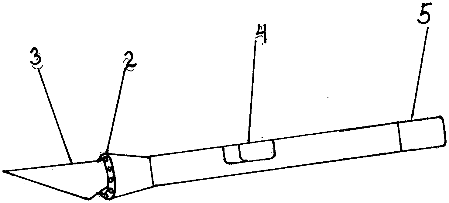
[0006] FIG. 3 Shows a three dimensional view of an angular shaped optic scalpel with led lights around the base of the blade.
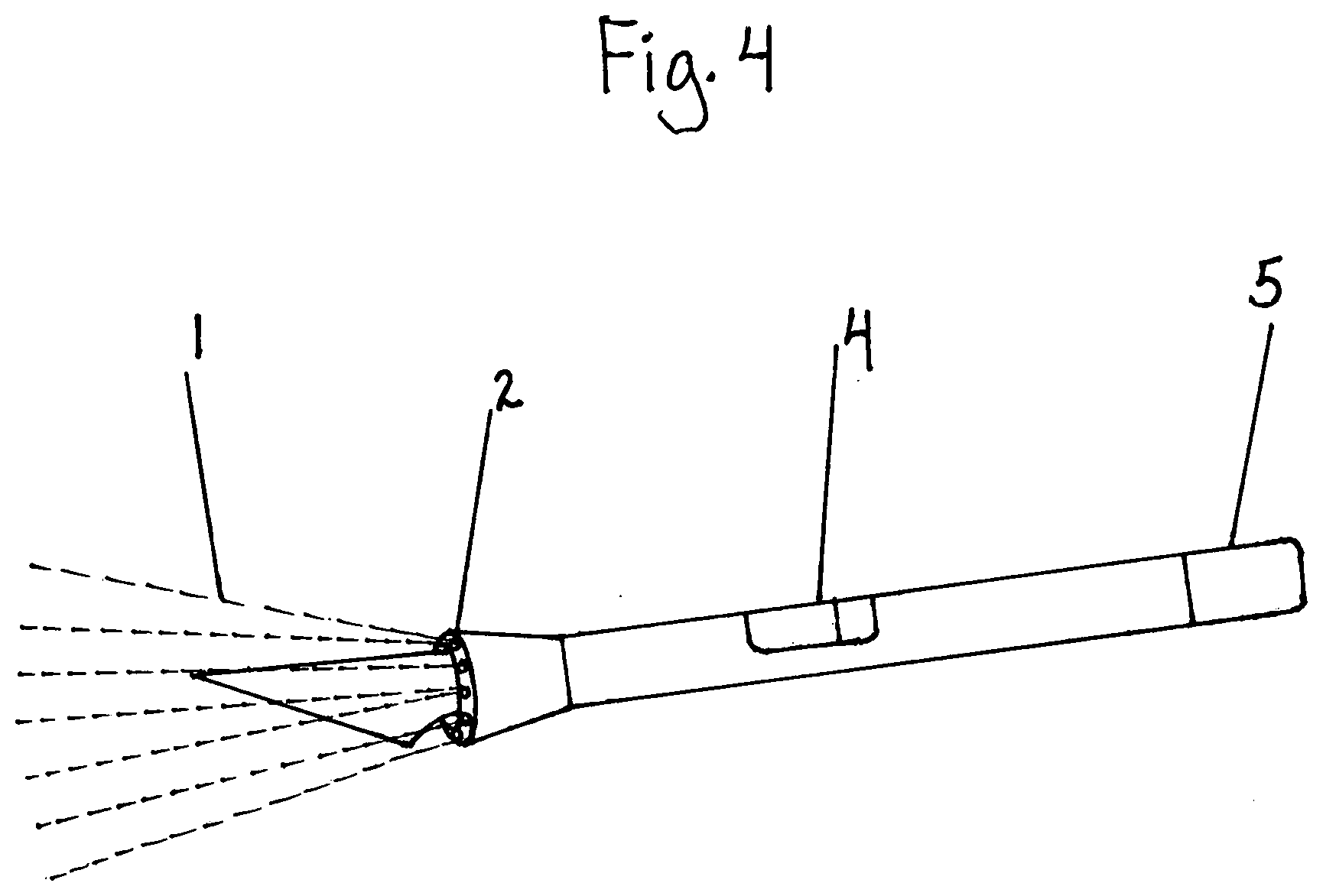
[0007] FIG. 4 Drawing shows a three dimensional view of an angular shaped optic scalpel knife with activated led lights 2. The dots 1, around the base of the blade represent light emissions from led lights 2. This drawing also shows the activation switch 4, pushed forward.
[0008] FIG. 5 This drawing shows the top view of the configuration of led lights encased in in handle tip frame around the optic scalpel blade.
[0009] FIG. 6 Is a three dimensional view of the optic scalpel showing the bottom tip 5, separated from the central handle. The bottom is screwed off for cell battery insertion or removal.
DETAILED DESCRIPTION OF THE EMBODIMENTS OF THE INVENTION
[0010] Below please see reference numbers used throughout the description to refer to elements in the drawings:
[0011] 1 Light emissions
[0012] 2 lights around the base
[0013] 3 Knife Blade
[0014] 4 Light Switch
[0015] 5 Bottom end of Handle
* * * * *
D00000
D00001
D00002
D00003
D00004
D00005
D00006
XML
uspto.report is an independent third-party trademark research tool that is not affiliated, endorsed, or sponsored by the United States Patent and Trademark Office (USPTO) or any other governmental organization. The information provided by uspto.report is based on publicly available data at the time of writing and is intended for informational purposes only.
While we strive to provide accurate and up-to-date information, we do not guarantee the accuracy, completeness, reliability, or suitability of the information displayed on this site. The use of this site is at your own risk. Any reliance you place on such information is therefore strictly at your own risk.
All official trademark data, including owner information, should be verified by visiting the official USPTO website at www.uspto.gov. This site is not intended to replace professional legal advice and should not be used as a substitute for consulting with a legal professional who is knowledgeable about trademark law.