Backpack
Kind Code
U.S. patent application number 16/781042 was filed with the patent office on 2020-08-06 for backpack. The applicant listed for this patent is Under Armour, Inc.. Invention is credited to Jennifer Smith.
| Application Number | 20200245746 16/781042 |
| Document ID | 20200245746 / US20200245746 |
| Family ID | 1000004640115 |
| Filed Date | 2020-08-06 |
| Patent Application | download [pdf] |


View All Diagrams
| United States Patent Application | 20200245746 |
| Kind Code | A1 |
| Smith; Jennifer | August 6, 2020 |
Backpack
Abstract
An accessory article adapted to be positioned on a user's body includes a compartment and at least one strap. The compartment includes a top side, a bottom panel, a front panel, a rear panel, and two side panels extending therebetween. The at least one strap may be coupled to the rear panel of the compartment to permit wearing of the accessory article by the user. The front panel of the accessory article may be shorter in length than the rear panel such that the bottom panel may be angled or slanted with respect to a horizontal plane when the front and rear panels are oriented to be parallel to a vertical plane. The angled bottom panel promotes items disposed within the compartment to be disposed low and toward the rear panel of the accessory article.
| Inventors: | Smith; Jennifer; (Baltimore, MD) | ||||||||||
| Applicant: |
|
||||||||||
|---|---|---|---|---|---|---|---|---|---|---|---|
| Family ID: | 1000004640115 | ||||||||||
| Appl. No.: | 16/781042 | ||||||||||
| Filed: | February 4, 2020 |
Related U.S. Patent Documents
| Application Number | Filing Date | Patent Number | ||
|---|---|---|---|---|
| 62800816 | Feb 4, 2019 | |||
| Current U.S. Class: | 1/1 |
| Current CPC Class: | A45C 13/06 20130101; A45F 3/04 20130101 |
| International Class: | A45F 3/04 20060101 A45F003/04; A45C 13/06 20060101 A45C013/06 |
Claims
1. A backpack comprising: a compartment including: a front panel, a rear panel, a first side panel, a second side panel, and a bottom panel disposed on a bottom side of the compart, the bottom panel being coupled to the front panel, the rear panel, the first side panel, and the second side panel, wherein the front panel has a first length and the rear panel has a second length, the second length being larger than the first length such that, when the front and rear panels are oriented parallel to a vertical plane, the bottom panel is offset from being parallel to a horizontal plane, thereby defining an inclining bottom surface within the compartment; and a shoulder strap coupled to the rear panel of the compartment.
2. The article of claim 1, wherein the bottom panel being offset from parallel to the horizontal plane orients objects disposed within the at least one cavity proximate to the rear panel.
3. The article of claim 1, where the rear panel has an upper end and a lower end, and the front panel has an upper end and a lower end, the upper end of the rear panel being disposed higher in height than the upper end of the front panel, and the lower end of the rear panel being disposed lower in height than the lower end of the front panel.
4. The article of claim 1, wherein the front panel, the rear panel, the first side panel, and the second side panel collectively define an opening to the cavity, the opening being disposed on a top side of the compartment, opposite the bottom panel.
5. The article of claim 4, wherein when the front and rear panels are oriented parallel to the vertical plane, the opening is offset from being parallel to the horizontal plane.
6. The article of claim 4, wherein a lid compartment is coupled to the rear panel proximate to the opening, the lid compartment being reconfigurable between a closed position, where the lid compartment covers the opening, and an open position, where the opening is exposed.
7. The article of claim 6, wherein a zipper mechanism secures the lid compartment in the closed position.
8. The article of claim 1, wherein extending downwardly from the bottom panel proximate to the front panel is a rigid extension member configured to at least partially support the article on a support surface.
9. An article adapted to be positioned on a back of a user, the article comprising: at least one compartment including: a front panel having a top edge and a bottom edge, a rear panel having a top edge and a bottom edge, a first side panel coupled to the front panel and the rear panel, a second side panel coupled to the front panel and the rear panel, and a bottom panel coupled to the first side panel, the second side panel, the bottom edge of the front panel, and the bottom edge of the rear panel, wherein the bottom panel slopes downwardly from the bottom edge of the front panel to the bottom edge of the rear panel when the front and rear panels are oriented parallel to a vertical plane; and at least one strap at least partially coupled to the rear panel of the at least one compartment.
10. The article of claim 9, wherein the bottom panel sloping downwardly orients objects disposed within the at least one compartment proximate to the rear panel.
11. The article of claim 9, wherein, when the bottom panel is placed flat on a support surface, the front panel and the rear panel are offset from being parallel to the vertical plane.
12. The article of claim 9, wherein the top edge of the front panel, the top edge of the rear panel, a top edge of the first side panel, and a top edge of the second side panel collectively define an opening of the at least one compartment.
13. The article of claim 12, wherein a lid is coupled to the top edge of the rear panel proximate to the opening, the lid being reconfigurable between a closed position, where the lid covers the opening, and an open position, where the opening exposes an interior of the at least one compartment.
14. The article of claim 13, wherein the at least one compartment is a first compartment, and the lid defines a second compartment of the article.
15. An article adapted to be positioned on a back of a user, the article comprising: at least one compartment including: a front panel having a top edge and a bottom edge, a rear panel having a top edge and a bottom edge, a pair of side panels coupled to the front panel and the rear panel, each of the side panels having a top edge and a bottom edge, the top edge of each of the side panels slopes downwardly from the top edge of the rear panel to the top edge of the front panel when the front and rear panels are oriented parallel to a vertical plane, and the bottom edge of each of the side panels slopes upwardly from the bottom edge of the rear panel to the bottom edge of the front panel when the front and rear panels are oriented parallel to the vertical plane, and a bottom panel coupled to the bottom edge of each of the side panels, the bottom edge of the front panel, and the bottom edge of the rear panel.
16. The article of claim 15, wherein the bottom panel being coupled to the bottom edge of each of the pair of side panels that slopes upwardly from the bottom edge of the rear panel to the bottom edge of the front panel causes the bottom panel to be offset from a horizontal plane when the front and rear panels are oriented parallel to the vertical plane, where the offset of the bottom panel orients objects disposed within the at least one compartment proximate to the rear panel.
17. The article of claim 15, wherein the top edge of the front panel, the top edge of the rear panel, and the top edge of each of the pair of side panels collectively define an opening of the at least one compartment.
18. The article of claim 17, wherein, when the front and rear panels are oriented parallel to the vertical plane, the opening slopes downwardly from the rear panel to the front panel.
19. The article of claim 18, wherein, when the bottom panel is placed flat on a support surface, the front panel and the rear panel are offset from being parallel to the vertical plane.
20. The article of claim 19, wherein, when the bottom panel is placed flat on the support surface, an interior of the at least one compartment is visible from a viewpoint that faces a front side of the at least one compartment at an angle that is perpendicular to the vertical plane.
Description
CROSS-REFERENCE TO RELATED APPLICATIONS
[0001] This application claims priority under 35 U.S.C. 119(e) to U.S. Provisional Patent Application Ser. No. 62/800,816, entitled "Article with Weight Distribution Features", filed Feb. 4, 2019, the disclosure of which is incorporated herein by reference in its entirety for all purposes.
FIELD OF THE INVENTION
[0002] The present invention relates to an accessory article and, in particular, an accessory article with straps that may be worn by a user where the accessory article is disposed against the back of the user.
BACKGROUND OF THE INVENTION
[0003] Conventional bags, especially backpacks, often include shoulder straps that enable the backpacks to be worn over the shoulder of a user such that the bags are disposed against the back of the user. When the conventional bags are packed with heavy objects (e.g., books, laptops, etc.), the heavy objects are randomly positioned within the bag, generating a weight imbalance that causes the user to carry the conventional bag with an improper posture, with the user's back is hunched over and their head is disposed forward of their torso (i.e., an extended neck). Prolonged exposure to improper postures can strain various parts of a user's body, resulting in back (both lower and upper), neck, shoulder, hip, and/or even knee pain. Thus, these conventional bags do not provide sufficient weight distribution features for objects disposed within the conventional bags.
[0004] It would be desirable to provide a configured to address the above described deficiencies.
SUMMARY OF THE INVENTION
[0005] The present invention is directed toward an article adapted to be positioned on a user's back. The article may include at least one compartment and at least one strap. The at least one compartment may include a front panel, a rear panel, a first side panel coupled to the front panel and the rear panel, a second side panel coupled to the front panel and the rear panel, and a bottom panel coupled to the front panel, the rear panel, the first side panel, and the second side panel. The front panel, the rear panel, the first side panel, the second side panel, and the bottom panel may collectively define at least one cavity. The front panel of the at least one compartment may have a first length, and the rear panel of the at least one compartment may have a second length. The second length may be larger than the first length. Thus, when the front and rear panels are oriented parallel to a vertical plane, the bottom panel may be offset from being parallel to a horizontal plane. In other words, the bottom panel may be angled or slanted with respect to the horizontal plane such that the bottom panel intersects the horizontal plane. The at least one strap may be at least partially coupled to the rear panel of the at least one compartment.
[0006] The above and still further features and advantages of the present invention will become apparent upon consideration of the following detailed description of specific embodiments thereof.
BRIEF DESCRIPTION OF THE DRAWINGS
[0007] FIG. 1A illustrates a front elevational view of an embodiment of a bag assembly according to the present invention.
[0008] FIG. 1B illustrates a rear elevational view of the embodiment of the bag assembly illustrated in FIG. 1A.
[0009] FIG. 1C illustrates a side elevational view of a first side of the embodiment of the bag assembly illustrated in FIG. 1A.
[0010] FIG. 1D illustrates a side elevational view of a second side of the embodiment of the bag assembly illustrated in FIG. 1A.
[0011] FIG. 1E illustrates a side elevational view of the second side of the embodiment of the bag assembly illustrated in FIG. 1A while the bag assembly is worn on the back of a user.
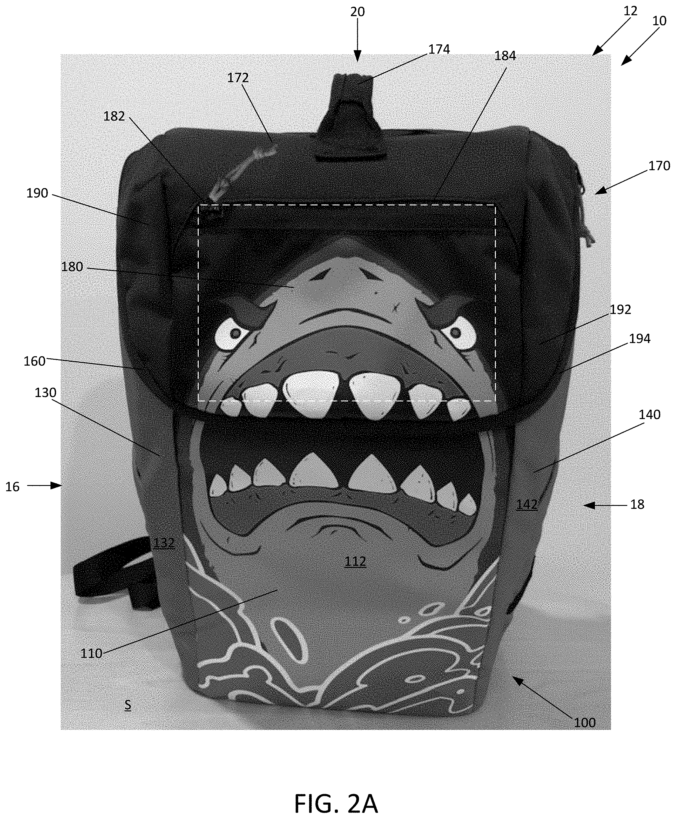
[0012] FIG. 2A illustrates a front elevational view of the embodiment of the bag assembly illustrated in FIG. 1A, the bag assembly being placed on a support surface and the lid compartment being oriented in the closed position.
[0013] FIG. 2B illustrates a side elevational view of the second side of the embodiment of the bag assembly illustrated in FIG. 1A, the bag assembly being placed on a support surface and the lid compartment being oriented in the closed position.
[0014] FIG. 3A illustrates a front elevational view of the embodiment of the bag assembly illustrated in FIG. 1A, the bag assembly being placed on a support surface and the lid compartment being oriented in the open position.
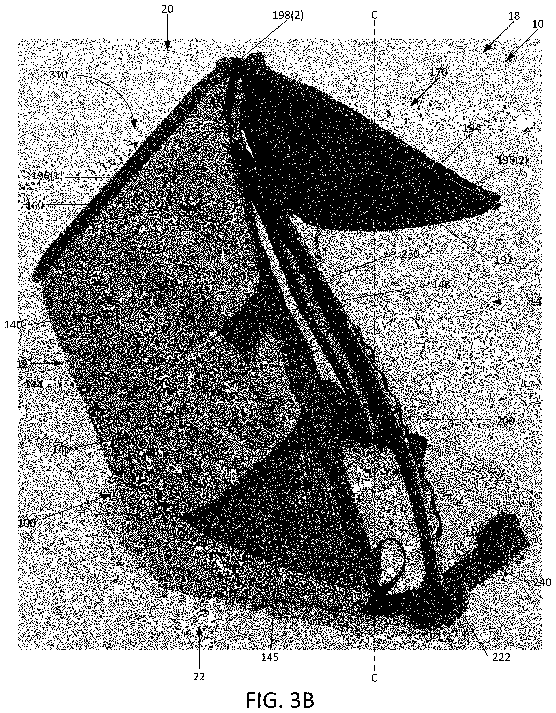
[0015] FIG. 3B illustrates a side elevational view of the second side of the embodiment of the bag assembly illustrated in FIG. 1A, the bag assembly being placed on a support surface and the lid compartment being oriented in the open position.
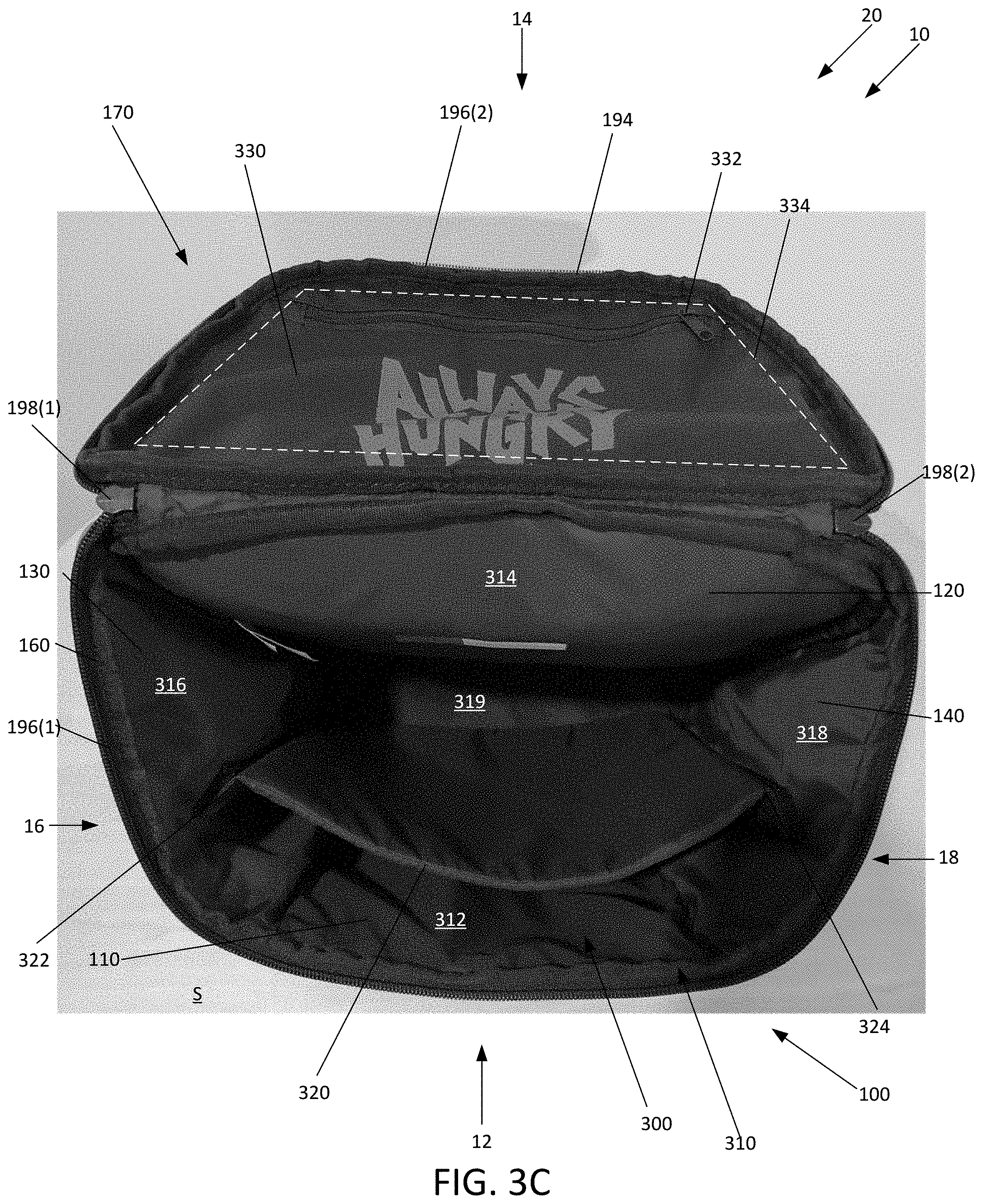
[0016] FIG. 3C illustrates a top view of the embodiment of the bag assembly illustrated in FIG. 1A, the bag assembly being placed on a support surface and the lid compartment being oriented in the open position.
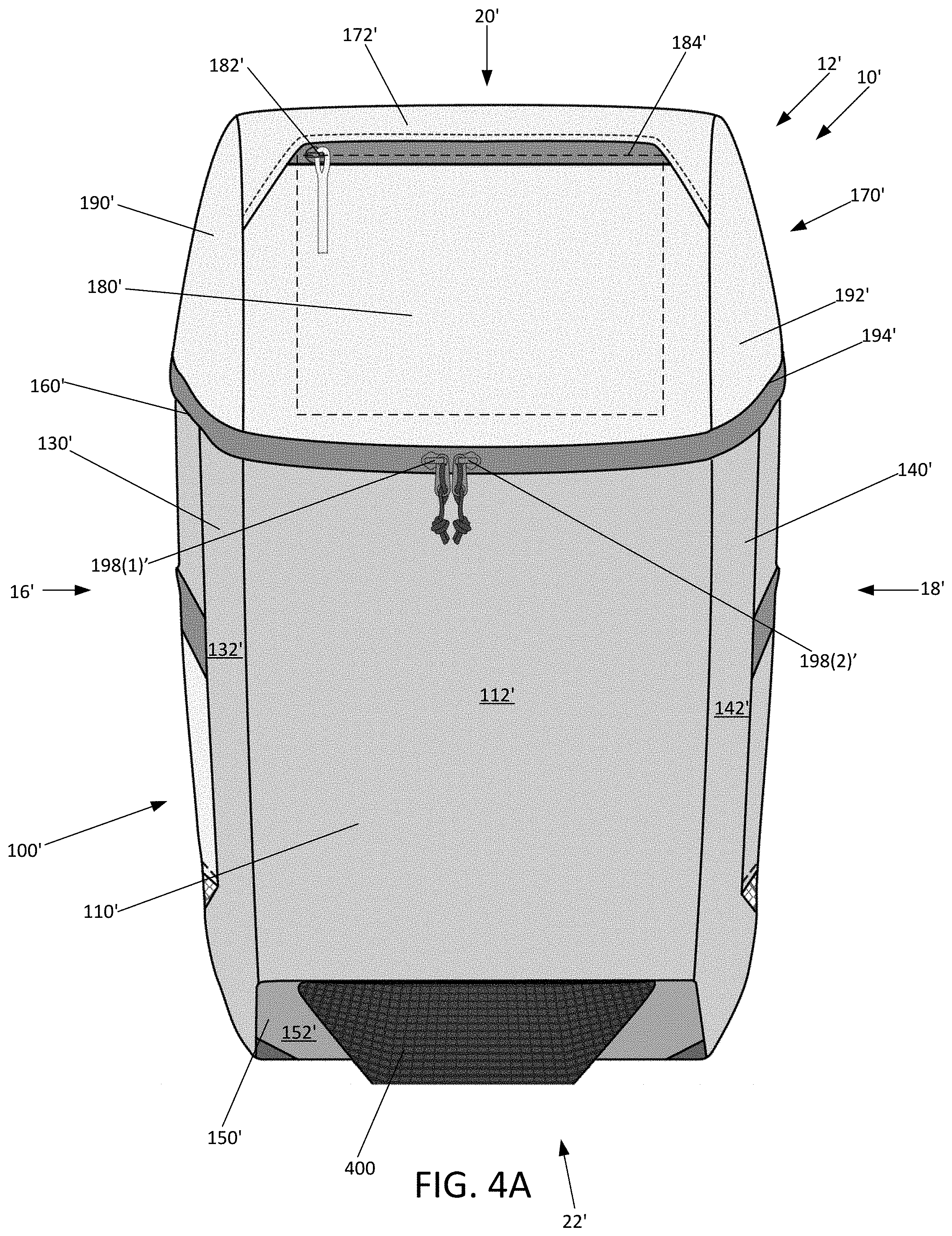
[0017] FIG. 4A illustrates a front elevational view of a second embodiment of a bag assembly according to the present invention.
[0018] FIG. 4B illustrates a side elevational view of a first side of the embodiment of the bag assembly illustrated in FIG. 4A.
[0019] FIG. 5A illustrates a front elevational view of a third embodiment of a bag assembly according to the present invention.
[0020] FIG. 5B illustrates a side elevational view of the first side of the embodiment of the bag assembly illustrated in FIG. 5A.
[0021] FIG. 6A illustrates a schematic drawing of the weight distribution of items disposed within one of the embodiments of the bag described herein.
[0022] FIG. 6B illustrates a schematic drawing of interior of the bag illustrated in FIG. 6A and the weight distribution of items disposed within the bag illustrated in FIG. 6A.
[0023] Like reference numerals have been used to identify like elements throughout this disclosure.
DETAILED DESCRIPTION OF THE INVENTION
[0024] The present invention relates to an accessory article adapted to be worn on the back of a user, where the article includes at least one strap. More specifically, the present invention relates to an accessory article, such as a backpack, where the bottom and/or top surface of the accessory article is slanted with respect to a horizontal plane (i.e., the bottom surface is angled with respect to the horizontal plane such that the bottom surface is not parallel to the horizontal plane). This promotes an efficient and effective weight distribution of objects disposed within the accessory article, where the slanted bottom surface positions objects low and against the back of the user when the accessory article is worn.
[0025] In the following detailed description, reference is made to the accompanying figures which form a part hereof wherein like numerals designate like parts throughout, and in which is shown, by way of illustration, embodiments that may be practiced. It is to be understood that other embodiments may be utilized, and structural or logical changes may be made without departing from the scope of the present disclosure. Therefore, the following detailed description is not to be taken in a limiting sense, and the scope of embodiments is defined by the appended claims and their equivalents.
[0026] Aspects of the disclosure are disclosed in the description herein. Alternate embodiments of the present disclosure and their equivalents may be devised without parting from the spirit or scope of the present disclosure. It should be noted that any discussion herein regarding "one embodiment", "an embodiment", "an exemplary embodiment", and the like indicate that the embodiment described may include a particular feature, structure, or characteristic, and that such particular feature, structure, or characteristic may not necessarily be included in every embodiment. In addition, references to the foregoing do not necessarily comprise a reference to the same embodiment. Finally, irrespective of whether it is explicitly described, one of ordinary skill in the art would readily appreciate that each of the particular features, structures, or characteristics of the given embodiments may be utilized in connection or combination with those of any other embodiment discussed herein.
[0027] Various operations may be described as multiple discrete actions or operations in turn, in a manner that is most helpful in understanding the claimed subject matter. However, the order of description should not be construed as to imply that these operations are necessarily order dependent. In particular, these operations may not be performed in the order of presentation. Operations described may be performed in a different order than the described embodiment. Various additional operations may be performed and/or described operations may be omitted in additional embodiments.
[0028] For the purposes of the present disclosure, the phrase "A and/or B" means (A), (B), or (A and B). For the purposes of the present disclosure, the phrase "A, B, and/or C" means (A), (B), (C), (A and B), (A and C), (B and C), or (A, B and C).
[0029] The terms "comprising," "including," "having," and the like, as used with respect to embodiments of the present disclosure, are synonymous.
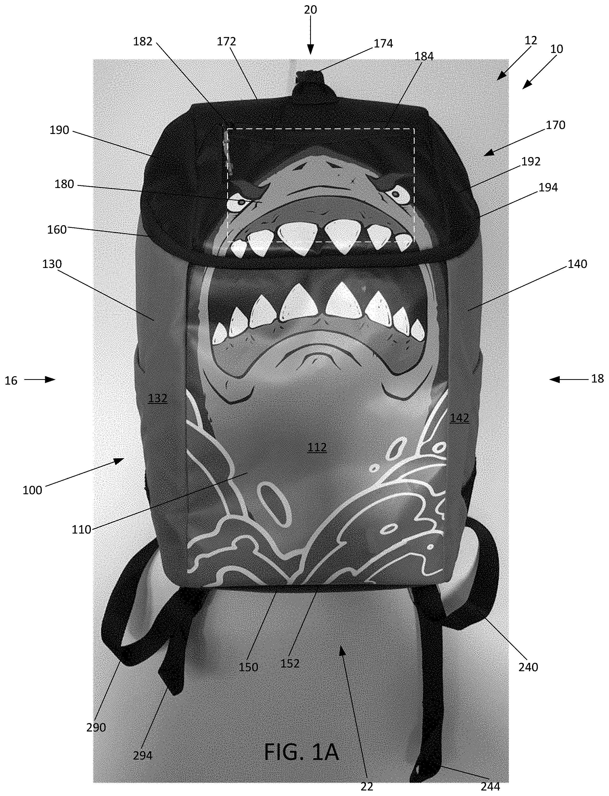
[0030] With general reference to FIGS. 1A, 1B, 1C, 1D, and 1E an article or bag assembly 10 to be worn or carried by a user is shown. The term bag assembly may refer to any type of bag, including, but not limited to, backpack, duffle bag, luggage, purse, gym bag, etc. The embodiment of the bag assembly 10 illustrated in FIGS. 1A, 1B, 1C, 1D, and 1E is a backpack configured to be worn across/on a user's back. The bag assembly 10 is generally a rectangular parallelpiped that includes a front side 12, a rear side 14 opposite the front side 12, a first lateral side 16 spanning from the front side 12 to the rear side 14, and a second lateral side 18 opposite the first lateral side spanning from the front side 12 to the rear side 14. The bag assembly 10 further includes a top side 20 spanning between the front and rear sides 12, 14 and the first and second sides 16, 18, and an opposite bottom side 22 that also spans between the front and rear sides 12, 14 and the first and second sides 16, 18.
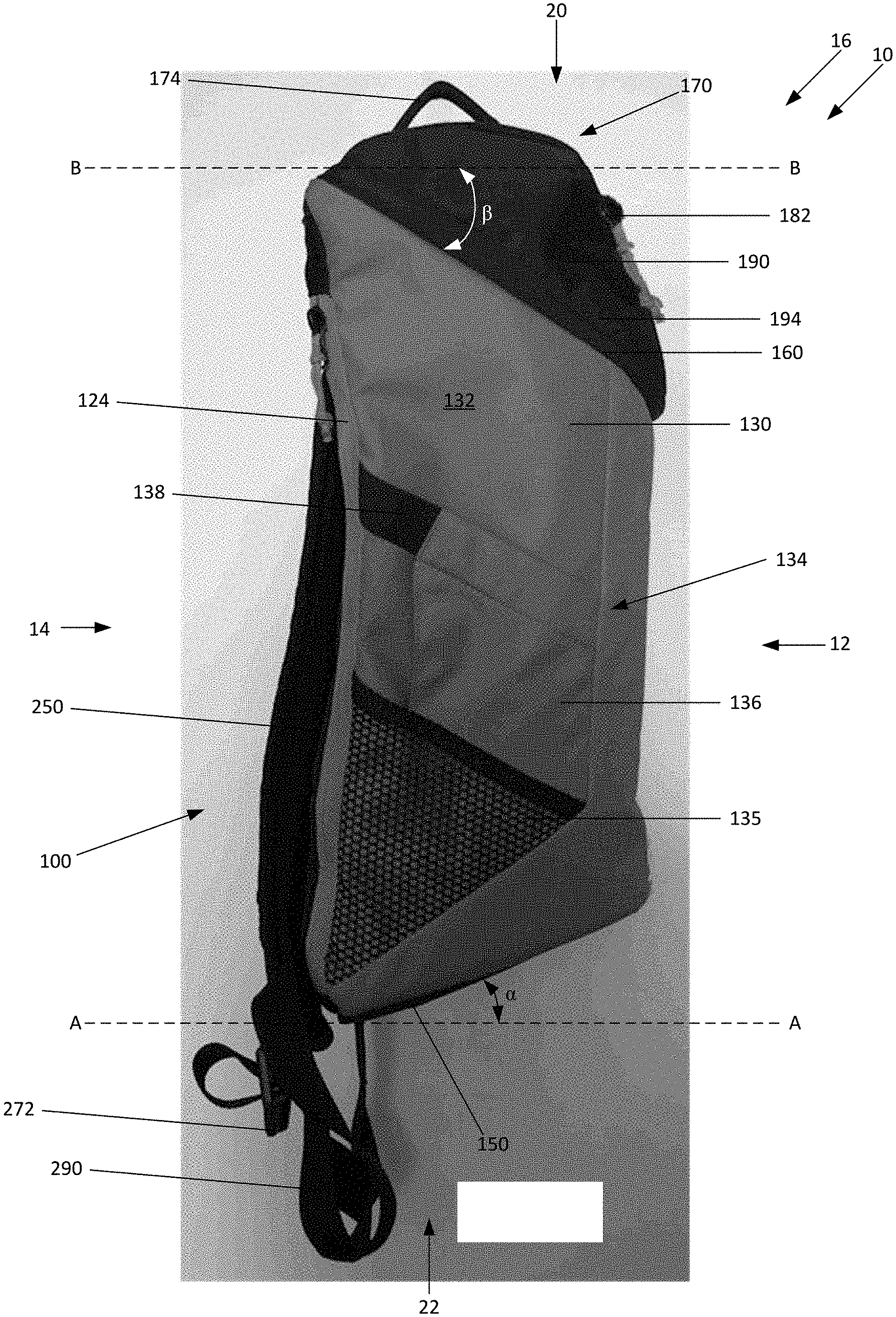
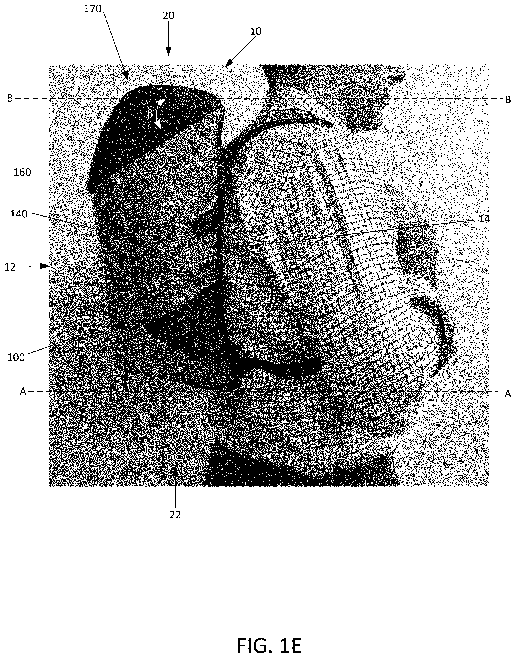
[0031] As illustrated in FIGS. 1A, 1B, 1C, 1D, and 1E, the bag assembly 10 includes a main compartment 100, a lid compartment 170 hingedly coupled to the main compartment 100, and a pair of straps 200, 250 coupled to the main compartment 100. The main compartment 100 may generally be a trapezoidal prism with a front panel 110 (see FIG. 1A), a rear panel 120 opposite the front panel 110 (see FIG. 1B), a first side panel 130 coupled to both of the front panel 110 and the rear panel 120 (see FIG. 1C), and a second side panel 140 opposite the first side panel 130 and coupled to both the front panel 110 and the rear panel 120 (see FIG. 1D). The main compartment 100 further includes a bottom panel 150 that is coupled to the front panel 110, the rear panel 120, the first side panel 130, and the second side panel 140. The front panel 110 may be shorter in both length and width than the rear panel 120. As best illustrated in FIGS. 1C and 1D, the bottom edge of the rear panel 120 is disposed lower in height than the bottom edge of the front panel 110, while the top edge of the rear panel 120 is disposed higher in height than the top edge of the front panel 110. Thus, the bottom edges of the first and second side panels 130, 140 are slanted/angled, such that, when the bag assembly 10 is oriented in a substantially vertical orientation (i.e., such as when worn on the back of the user as illustrated in FIG. 1E) at least the bottom panel 150 is offset from a horizontal plane A-A by an angle .alpha.. In other words, the bottom panel 150 is oriented in a plane that intersects the horizontal plane A-A at an angle .alpha., such that the bottom panel 150 is not parallel to the horizontal plane A-A. In some embodiments, the angle .alpha. may be approximately 45 degrees, plus or minus 20 degrees. FIGS. 1C and 1D further illustrate that the bottom panel 150 may be angled such that the bottom panel 150 slants downwardly from the front panel 110 to the rear panel 120, where the portion of the bottom panel 150 coupled to the front panel 110 may be higher in height than the portion of the bottom panel 150 coupled to the rear panel 120.
[0032] FIGS. 1A, 1B, 1C, 1D, and 1E further illustrate that the front panel 110, the rear panel 120, the first side panel 130, and the second side panel 140 of the main compartment 100 collectively define a top edge 160. As best illustrated in FIGS. 1C and 1D, the top edge 160 of the main compartment 100 may be offset from a horizontal plane B-B such that, when the bag assembly 10 is oriented in a substantially vertical orientation (i.e., such as when worn on the back of a user), the portion of the top edge 160 formed by the front panel 110 is disposed lower in height than the portion of the top edge 160 formed by the rear panel 120. In other words, the top edge 160 of the main compartment 100 is oriented in a plane that intersects the horizontal plane B-B at an angle .beta., such that the bottom panel 150 is not parallel to the horizontal plane B-B. Thus, the top edge 160 may be slanted or angled with respect to the horizontal plan B-B by an angle .beta.. In some embodiments, the angle .beta. may be approximately 45 degrees, plus or minus 20 degrees.
[0033] Turning to FIGS. 3A, and 3C, the front panel 110, the rear panel 120, the first side panel 130, the second side panel 140, and the rear panel 120 may collectively define an interior cavity 300. An opening 310 defined by the top edge 160 may provide access to the cavity 300. As best illustrated in FIGS. 1A and 3C, the front panel 110 may include an exterior surface 112 and an opposite interior surface 312. Similarly, as illustrated in FIGS. 1B, 3A, and 3C, the rear panel 120 may include an exterior surface 122 and an opposite interior surface 314. FIGS. 1C, 1D, 3A, and 3C further illustrate that the first side panel 130 may also include an exterior surface 132 and an opposite interior surface 316, and that the second side panel 140 may include an exterior surface 142 and an opposite interior surface 318. In addition, FIGS. 1A, 1C, 1D, and 3C illustrate that the bottom surface 150 also includes an exterior surface 152 and an opposite interior surface 319. The interior surfaces 312, 314, 316, 318, 319 of the panels 110, 120, 130, 140, 150 all face into the cavity 300.
[0034] With this configuration, the backpack is self-supporting, i.e., it stands without support. The backpack, moreover is pitched forward. The closed end of the bag defined by the flat bottom panel that inclines from back to front causes the entire backpack compartment (including the cavity) to tilt forward when the backpack is placed on a generally level (horizontal) surface. The open (top) side of the bag, moreover, declines from back to front. Accordingly, the opening is offset with the front of the opening being positioned below the rear of the opening. This configuration (slanted top and/or bottom sides) permits a user to easily load items into and/or unload items out of the compartment cavity 300.
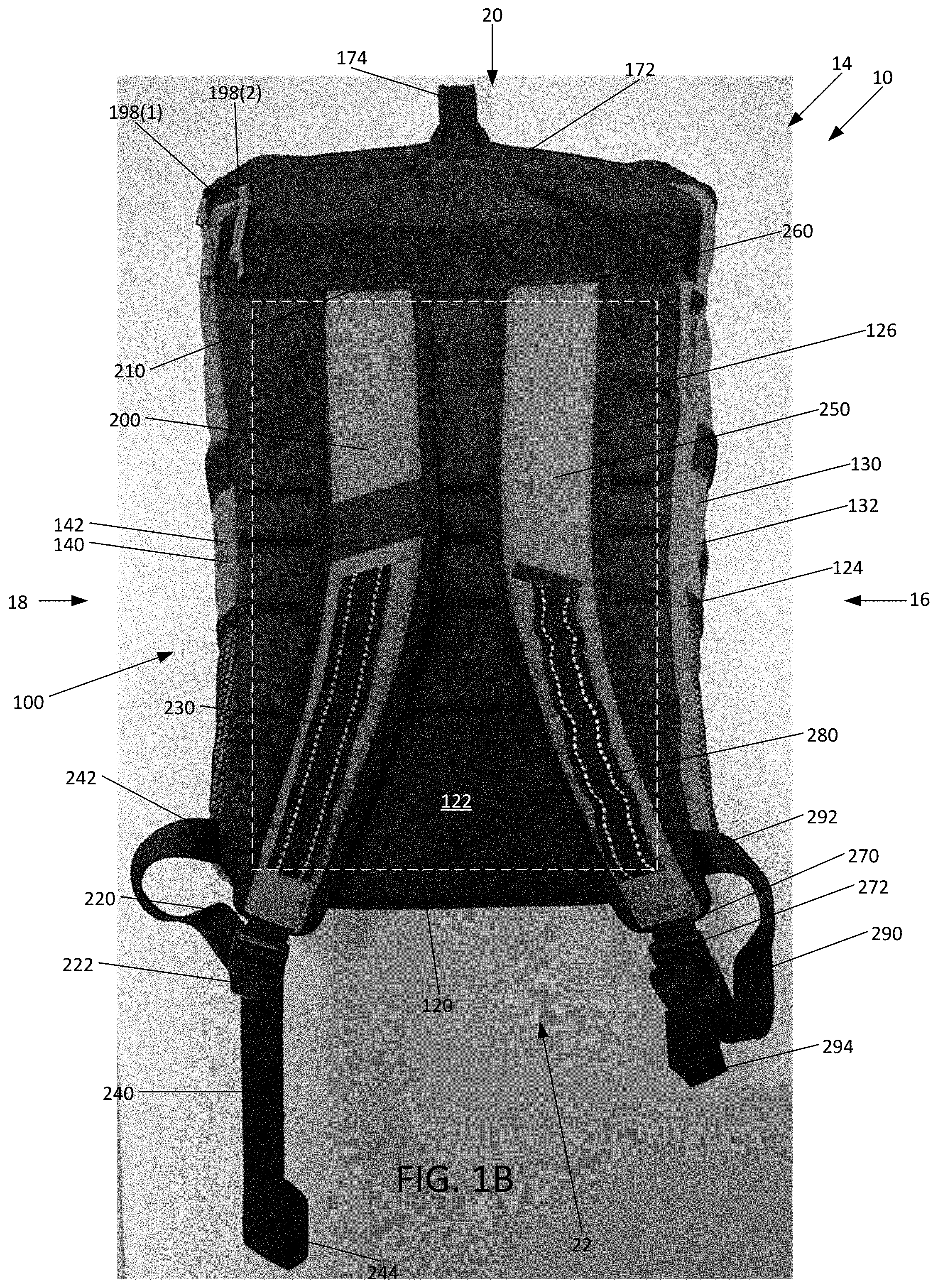
[0035] Returning to FIGS. 1B and 1C, the rear panel 120 includes a zipper 124 disposed in a vertical orientation proximate to the coupling of the first side panel 130 with the rear panel 120. The vertical zipper 124 may span from proximate to the bottom surface 150 to proximate to the top edge 160. The zipper 124 may provide access to a pocket 126 that is disposed between the exterior surface 122 of the rear panel 120 and the interior surface 314 of the rear panel 120. The pocket 126 may span the width and length of the rear panel 120. Furthermore, because the rear panel 120 is disposed against the user when the bag assembly 120 is worn by the user, the rear panel 120 may be constructed with a foam material disposed within the rear panel 120 (i.e., between the exterior surface 122 and the interior surface 314) that enables the bag assembly 10 to comfortably sit against the back of a user wearing the bag assembly 10 (as illustrated in FIG. 1E).
[0036] As illustrated in FIG. 1C, disposed on the exterior surface 132 of the first side panel 130 is a first side receptacle 134. The first side receptacle 134 may include a mesh portion 135, a fabric portion 136 coupled to the mesh portion 135, and a resilient member 138 coupled to the fabric portion 136. The mesh portion 135 may be coupled to the exterior surface 132 of the first side receptacle 134 proximate to the rear panel 120, the vertical zipper 124 of the rear panel 120, and the bottom panel 150. The fabric portion 136 may be at least partially coupled to the mesh portion 125 and the exterior surface 132, while the resilient member 138 may be coupled to the fabric portion 136 and to the coupling of the rear panel 120 to the first side panel 130. The mesh portion 135, fabric portion 136, and resilient member 138 of the first side pocket 132 may collectively define the first side receptacle 134 on the exterior surface 132 of the first side panel 130 for receiving and storing items (e.g., water bottles).
[0037] As illustrated in FIG. 1D, and similar to the first side panel 130, disposed on the exterior surface 142 of the second side panel 140 is a second side receptacle 144. The second side receptacle 144 may include a mesh portion 145, a fabric portion 146 coupled to the mesh portion 145, and a resilient member 148 coupled to the fabric portion 146. The mesh portion 145 may be coupled to the exterior surface 142 of the second side receptacle 144 proximate to the rear panel 120 and the bottom panel 150. The fabric portion 146 of the second side panel 140 may be at least partially coupled to the mesh portion 145 and the exterior surface 142 of the second side panel 140, while the resilient member 148 may be coupled to the fabric portion 146 and the coupling of the rear panel 120 to the second side panel 140. Like the first side receptacle 134, the mesh portion 145, fabric portion 146, and resilient member 148 of the second side pocket 142 may collectively define the second side receptacle 144 on the exterior surface 142 of the second side panel 140 for receiving and storing items (e.g., water bottles).
[0038] In some embodiments, the front panel 110, the rear panel 120, the first side panel 130, the second side panel 140, and the bottom panel 150 may each contain a rigid structure between the exterior surfaces 112, 122, 132, 142, 152, and the interior surfaces 312, 314, 316, 318, 319 of the panels 110, 120, 130, 140, 150 to enable the bag assembly to retain its shape, especially with respect to the angled orientation of the bottom panel 150 with respect to the horizontal plane A-A.
[0039] Continuing with FIGS. 1A, 1B, 1C, and 1D, the lid compartment 170 may be a generally triangular prism with a top panel 172, a front panel 180, a first side panel 190, and a second side panel 192. The top panel 172 and the front panel 180 may both be substantially rectangular, while the first and second side panels 190, 192 of the lid compartment 170 may be substantially triangular in shape. As best illustrated in FIGS. 1A, 1B, 1C, 1D and 3C, the top panel 172, the front panel 180, the first side panel 190, and the second side panel 192 of the lid compartment 170 may collectively define a bottom edge 194. The portion of the bottom edge 194 formed by the top panel 172 may be hingedly coupled to the portion of the top edge 160 formed by the rear panel 120 of the main compartment 100. Thus, the top panel 172 of the lid compartment 170 may be hingedly coupled to the rear panel 120 of the main compartment 100 to enable the lid compartment 170 to pivot with respect to the main compartment 100 about the coupling of the top panel 172 to the rear panel 120. The remaining portions of the top edge 160 (i.e., those portions formed by the front panel 110, the first side panel 130, and the second side panel 140) may by equipped with a first half of a zipper track 196(1), while the remaining portions of the bottom edge 194 (i.e., those portions formed by the front panel 180, the first side panel 190, and the second side panel 192) may be equipped with a second half of a zipper track 196(2). The first and second halves of the zipper track 196(1), 196(2) may interlock or intermesh with one another to secure the lid compartment 170 in the closed orientation (see FIGS. 1A, 1B, 1C, 1D, 2A, and 2B). One of two zipper sliders 198(1), 198(2) may slide along the zipper track halves 196(1), 196(2) to cause the zipper track halves 196(1), 196(2) to intermesh with one another, or unintermesh with one another (i.e., uncouple from one another), depending on the direction in which one of the two zipper sliders 198(1), 198(2) slides along the zipper track halves 196(1), 196(2).
[0040] As further illustrated in FIG. 1A, the top panel 172 of the lid compartment 170 may include a handle 174. The handle 174 may be disposed on the top panel 172 at a location that is equidistant from the first side panel 190 and the second side panel 192 of the lid compartment 170. The handle 174, moreover, may span across the top panel 172 from proximate the front panel 180 to proximate to the coupling of the top panel 172 of the lid compartment 170 to the rear panel 120 of the main compartment 100. The handle 174 may be utilized by a user of the bag assembly 10 to lift or pick up the bag assembly 10.
[0041] Continuing with FIG. 1A, the front panel 180 of the lid compartment 170 may include a zipper mechanism 182 that provides access to a front lid pocket 184 when the zipper mechanism 182 is oriented in the open position. The zipper mechanism 182 may be disposed on the front panel 180 in a generally horizontal orientation such that the zipper mechanism 182 spans across the front panel 180 from proximate to the first side panel 190 to proximate to the second side panel 192. As further illustrated in FIG. 1A, the zipper mechanism 182 may be further disposed on the front panel 180 of the lid compartment 170 such that the zipper mechanism 182 is disposed proximate to top panel 184.
[0042] Turning to FIG. 3C, the lid compartment 170 further includes a bottom panel 330 that is bordered by the bottom edge 194 of the lid compartment 170. Therefore, the bottom panel 330 may be coupled to the top panel 172, the front panel 180, the first side panel 190, and the second side panel 192. As illustrated in FIG. 3C, the bottom panel 330 may include a zipper mechanism 332 that may be opened or closed, and that, when opened, provides access to an interior pocket 334 disposed collectively defined by top panel 172, the front panel 180, the first side panel 190, the second side panel 192, and the bottom panel 330 of the lid compartment 170. This enables items to be stored in an interior space of the lid compartment 170 separate from the main compartment 100. In some embodiments, the interior pocket 334 may be the same as the front lid pocket 184, while in other embodiments, the two pockets 184, 334 may be isolated from one another (i.e., a panel or structure may separate the front lid pocket 184 from the interior pocket 334).
[0043] Turning back to FIG. 1B, coupled to the rear panel 120 of the main compartment 100 of the bag assembly 10 is a pair of shoulder straps 200, 250. The first shoulder strap 200 may contain a first end 210 and a second end 220, while the second shoulder strap 250 may also contain a first end 260 and a second end 270. The first ends 210, 260 of each shoulder strap 200, 250, respectively, may be coupled to the rear panel 120, while the second ends 220, 270 of each shoulder strap 200, 250 may be uncoupled from the rear panel 120. As illustrated, the first ends 210, 260 of the shoulder straps 200, 250 may be coupled to the rear panel 120 proximate to the top edge 160 (i.e., proximate to where the rear panel 120 of the main compartment 100 is coupled to the top panel 172 of the lid compartment 170), where the first end 210 of the first shoulder strap 200 may be disposed more proximate to the second side panel 140, and the first end 260 of the second shoulder strap 250 may be disposed more proximate to the first side panel 130. Each of the second ends 220, 270 of the straps 200, 250 may include a buckle 222, 272, respectively. In the embodiment illustrated, disposed on the shoulder straps 200, 250 between the first ends 210, 260 and the second ends 220, 270 are attachments loops 230, 280, respectively. The attachment loops 230, 280 facilitate the attachment of items or accessories (i.e., tags, keys, containers, etc.) to the shoulder straps 200, 250 to enable these items or accessories to be readily accessible to the user of the bag assembly 10.
[0044] As further illustrated in FIG. 1B, also attached to the rear panel 120 are a pair of tethers 240, 290. Like the shoulder straps 200, 250, the first tether 240 includes a first end 242 and a second end 244, while the second tether 290 includes a first end 292, and a second end 294. The first ends 242, 292 of each tether 240, 290, respectively, may be coupled to the rear panel 120, while the second ends 244, 294 of each tether 240, 290 may be uncoupled from the rear panel 120. More specifically, the first ends 242, 292 of the tethers 240, 290 may be coupled to the rear panel 120 proximate to the bottom panel 150, where the first end 242 of the first tether 240 may be disposed proximate to the coupling of the rear panel 120 to the second side panel 140, and the first end 292 of the second tether 290 may be disposed proximate to the coupling of the rear panel 120 to the first side panel 130. The tethers 240, 290 may be coupled to the second ends 220, 270 of the first and second shoulder straps 200, 250 by threading the second ends 242, 292 of the tethers 240, 290 through the buckles 222, 272 of the second ends 220, 270 of the first and second shoulder straps 200, 250. As illustrated, the second end 242 of the first tether 240 may be threaded through buckle 222 of the second end 220 of the first shoulder strap 200 such that the amount of the first tether 240 that is threaded through the buckle 222 may be adjusted to alter the distance the second end 220 of the shoulder strap 200 may be disposed away from the exterior surface 122 of the rear panel 120. Similarly, the second end 292 of the second tether 290 may be threaded through buckle 272 of the second end 270 of the second shoulder strap 250 such that the amount of the second tether 290 that is threaded through the buckle 272 may be adjusted to alter the distance the second end 270 of the second shoulder strap 250 may be disposed away from the exterior surface 122 of the rear panel 120. This enables the shoulder straps 200, 250 to be adjusted to a desired size or setting by the user for wearing the bag assembly 10. When the bag assembly 10 is worn by a user, the exterior surface 122 of the rear panel 120 of the bag assembly 10 may be disposed against the back of the user, the shoulder straps 200, 250 may extend over the user's shoulders and at least partially down the front of the user's torso, and the tethers 240, 290 may extend from the rear panel 120 under the user's arms to the second ends 220, 270 of the shoulder straps 200, 250 (as illustrated in FIG. 1E). The more each tether 240, 290 is threaded through the buckles 222, 272, respectively, the more limited the movement of the second ends 220, 270 of the straps 200, 250 is with respect to the rear panel 120.
[0045] Turning to FIGS. 2A, 2B, 3A, 3B, and 3C, because of the angled bottom panel 150, when the bag assembly 10 is placed on the support surface S (e.g., a table, desk, etc.), the bag assembly 10 is tilted forward such that the bag assembly 10, and specifically, the rear panel 120, is offset from a vertical plane C-C by an angle .gamma.. The structure of the front panel 110, the rear panel 120, the first side panel 130, the second side panel 140, and the bottom panel 150 enables the bag assembly 10 to retain its shape when placed on the support surface S with the bottom panel 150 placed against the support surface S. As illustrated best in FIGS. 2A and 2B, when the lid compartment 170 is in the closed position, the bottom panel 150 of the bag assembly 10 is disposed on a support surface S, and the bag assembly 10 is viewed from an angle that is perpendicular to the vertical plane C-C, the top panel 172 of the bag assembly 10 is visible to the viewer. Conversely, as best illustrated in FIGS. 3A and 3B, when the lid compartment 170 is in the open position, the bottom panel 150 of the bag assembly 10 is disposed on a support surface S, and the bag assembly is viewed from an angle that is perpendicular to the vertical plane C-C, the interior cavity 300 of the bag assembly 10 is visible to the view. The angled top edge 160 of the main compartment 100 further enables a user to view into the interior cavity 300 of the main compartment 100. Thus, the bag assembly 10 can be placed on a support surface S (e.g., a table, desk, etc.) in a bottom panel 150 down orientation and a user of the bag assembly 10 can reposition the lid compartment 170 to the open position and view any contents disposed within the interior cavity 300 of the main compartment 100 without having to reposition the bag assembly 10 or themselves to view inside the cavity 300.
[0046] As best illustrated in FIGS. 3A and 3C, the interior cavity 300 of the main compartment 100 may further include an internal divider panel 320. This internal divider panel 320 may be substantially planar with a first edge 322 and an opposite second edge 324. The internal divider panel 320 may be removably coupled within the interior cavity 300 of the main compartment 100. More specifically, the first edge 322 may be removably coupled to the interior surface 316 of the first side panel 130, and the second edge 324 may be removably coupled to the interior surface 318 of the second side panel 140. This enables the internal divider panel 320 to be installed within the interior cavity 300 when desired by the user of the bag assembly 10 to divide the interior cavity 300 into two compartments for storing items within the interior cavity 300. The internal divider panel 320 may also be removed whenever the user does not wish to divide the interior cavity 300 into compartments.
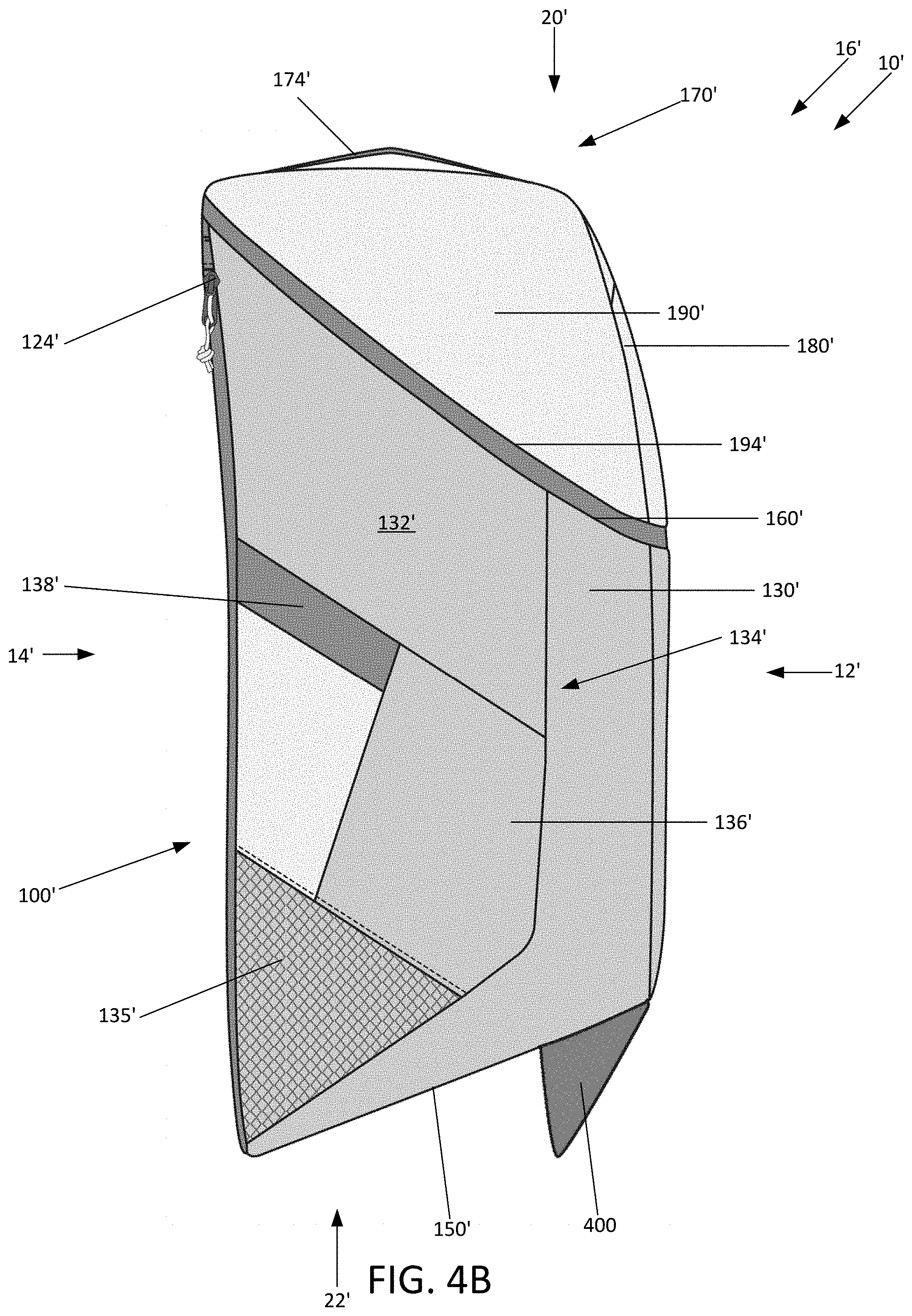
[0047] Turning to FIGS. 4A and 4B, a second embodiment of the bag assembly 10' may be substantially similar to the bag assembly 10 illustrated in FIGS. 1A, 1B, 1C, 1D, 2A, 2B, 3A, 3B, and 3C, except the second embodiment of the bag assembly 10' includes an extension member 400 (also called a kickstand) descending from the bottom panel 150' of the main compartment 100' of the bag assembly 10'. The extension member 400 may be disposed on the bottom panel 150 proximate to the coupling of the bottom panel 150 to the front panel 110' of the main compartment 100' of the bag assembly 10'. As further illustrated, the extension member 400 may span across the bottom panel 150' from proximate the first side panel 130' to proximate the second side panel 140'. The extension member 400 may be constructed from substantially rigid material such that the extension member supports the front side 12' of the second embodiment of the bag assembly 10' on a support surface S. In other words, when the second embodiment of the bag assembly 10' is placed bottom side 22 down, the extension member 400 and the portion of the bottom surface 150' that is coupled to the rear panel 120' collectively support the bag assembly 10' on the support surface S. Thus, the extension member 400 enables the bag assembly 10' to be placed on a support surface bottom panel 150' side down while maintaining the angled orientation of the bottom panel 150' (i.e., the bottom panel 150' being offset from a horizontal plane A-A by an angle .alpha.) and the front and rear panels 110', 120' being oriented in a substantially vertical orientation. The extension member 400 may further enable the bag assembly 10' to be more sturdily placed on a support surface S and reduces the likelihood the bag assembly 10' tips over or forward. In some embodiments, the extension member 400 may be reconfigurable between a deployed position, which is that shown in FIGS. 4A and 4B, and a stowed position, where the extension member is folded against the bottom surface 150', disposed within the bag assembly 10', or removed from the bag assembly 10' entirely.
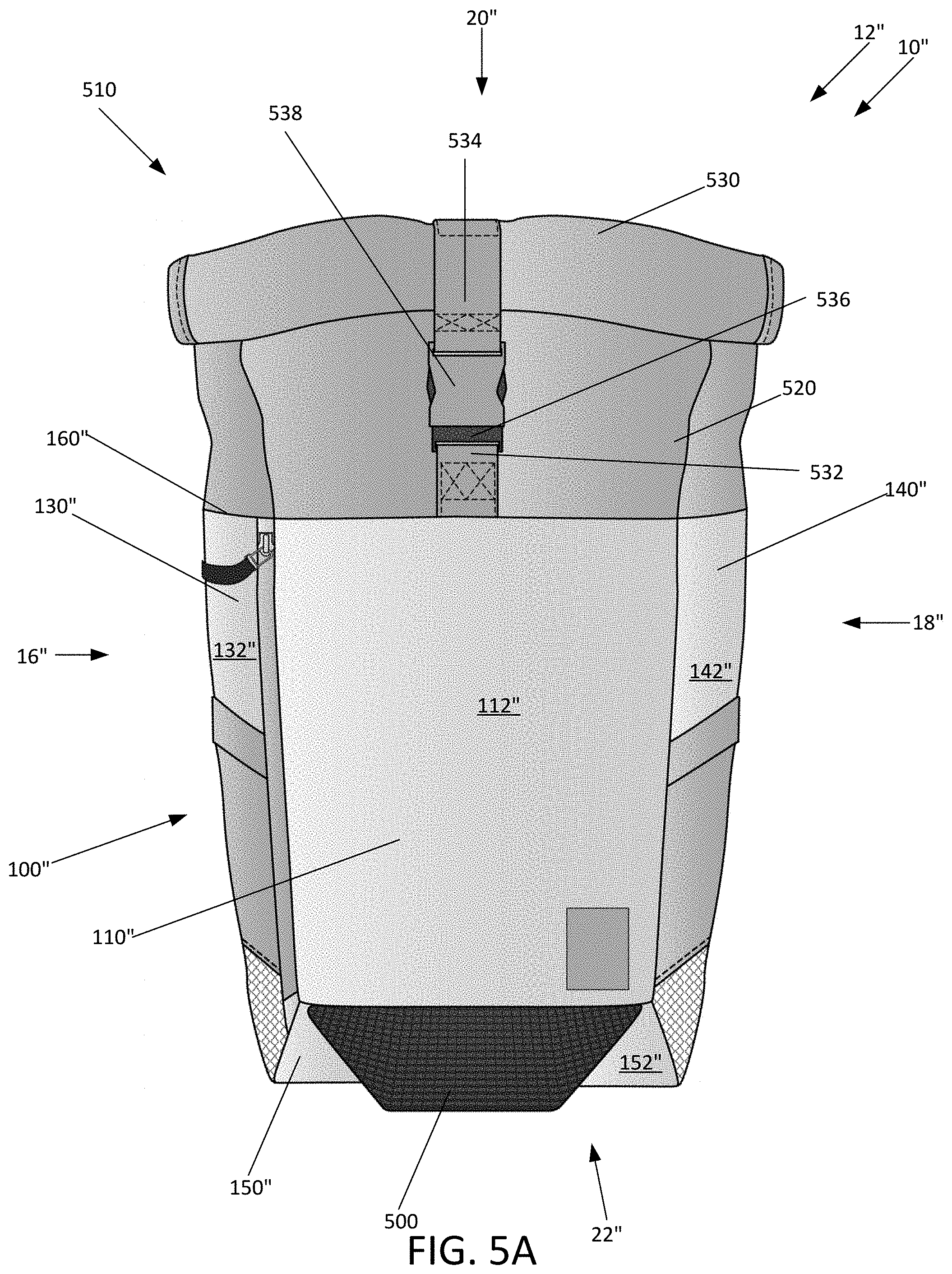
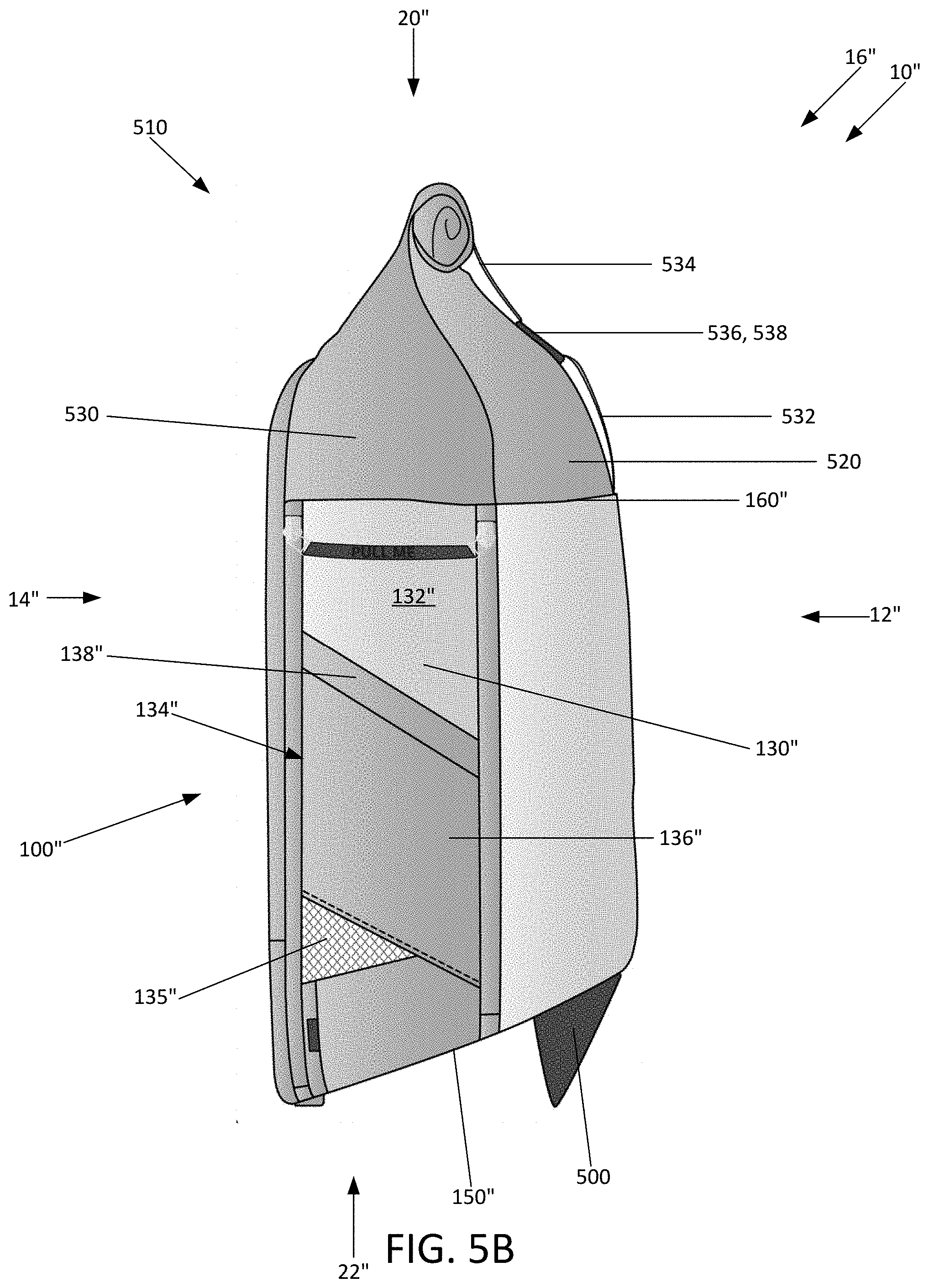
[0048] Turning to FIGS. 5A and 5B, a third embodiment of the bag assembly 10'' may be substantially similar to the second embodiment of the bag assembly 10' illustrated in FIGS. 4A and 4B (and thus substantially similar to the first embodiment of the bag assembly 10 illustrated in FIGS. 1A, 1B, 1C, 1D, 1E, 2A, 2B, 3A, 3B, and 3C), except the third embodiment of the bag assembly 10'' includes a roll top compartment 510 extending upwardly from the main compartment 100''. As illustrated, the top edge 160'' of the main compartment 10 may be aligned within a horizontal plane when the bag assembly 10'' is in a substantially vertical orientation (e.g., when supported by extension member 500 on a support surface or when worn on the back of a user). The roll top compartment 510 may include a first panel or portion 520 coupled to a second panel or portion 530. The first portion 520 of the roll top compartment 510 may be coupled to the front panel 110'', the first side panel 130'', and the second side panel 140'' of the main compartment 100'', while the second portion 530 of the roll top compartment 510 may be coupled to the rear panel 120'', the first side panel 130'', and the second side panel 140'' of the main compartment 100''. The first and second portions 520, 530 of the roll top compartment 510 may be uncoupled from one another at their top edges, which creates an opening when the first and second portions 520, 530 are in an unrolled state (not illustrated). This opening may provide access to the interior cavity 300'' of the main compartment 100''.
[0049] As further illustrated in FIGS. 5A and 5B, coupled to the first portion 520 is a lower strap 532 which contains a first buckle portion 536. The second portion 530 also includes an upper strap 534 which contains a second buckle portion 538. The first buckle portion 536 may be configured to mate with the second buckle portion 538. The first and second roll portions 520, 530 may be rolled together to close off access to the interior cavity 300'' of the main compartment 100'', where the first and second buckle portions 536, 538 may be mated with one another to secure the first and second roll portions 520, 530 in the rolled configuration shown. The roll top compartment 510 enables a user to adjust the volume of the interior cavity 300'' of the main compartment 100'' based on the amount the first and second roll portions 520, 530 are rolled toward the bottom side 22'' of the bag assembly 10''. The more the first and second portions 520, 530 are rolled, the smaller the volume of the interior cavity 300'' of the main compartment 100''. This enables the user to adjust the volume of the interior cavity 300'' to best accommodate the contents disposed within the interior cavity 300''. The roll top compartment 510 also provides a cost effective way of waterproofing the opening to the interior cavity 300''.
[0050] As explained above with respect to the second embodiment of the bag assembly 10', the extension member 500 may be disposed on the bottom panel 150'' of the main compartment 100'' to enable the third embodiment of the bag assembly 10'' to be placed on a support surface bottom panel 150'' side down while maintaining the angled orientation of the bottom panel 150'' (i.e., the bottom panel 150'' being offset from a horizontal plane A-A by an angle .alpha.) and the substantially vertical orientation of the front and rear panels 110'', 120''. Thus, the extension member 500 may enable the bag assembly 10'' to be more sturdily placed on a support surface S and reduces the likelihood the bag assembly 10'' tips over or forward. As previously explained, in some embodiments, the extension member 500 may be reconfigurable between a deployed position, which is that shown in FIGS. 5A and 5B, and a stowed position, where the extension member is folded against the bottom surface 150'', disposed within the bag assembly 10'', or removed from the bag assembly 10'' entirely.
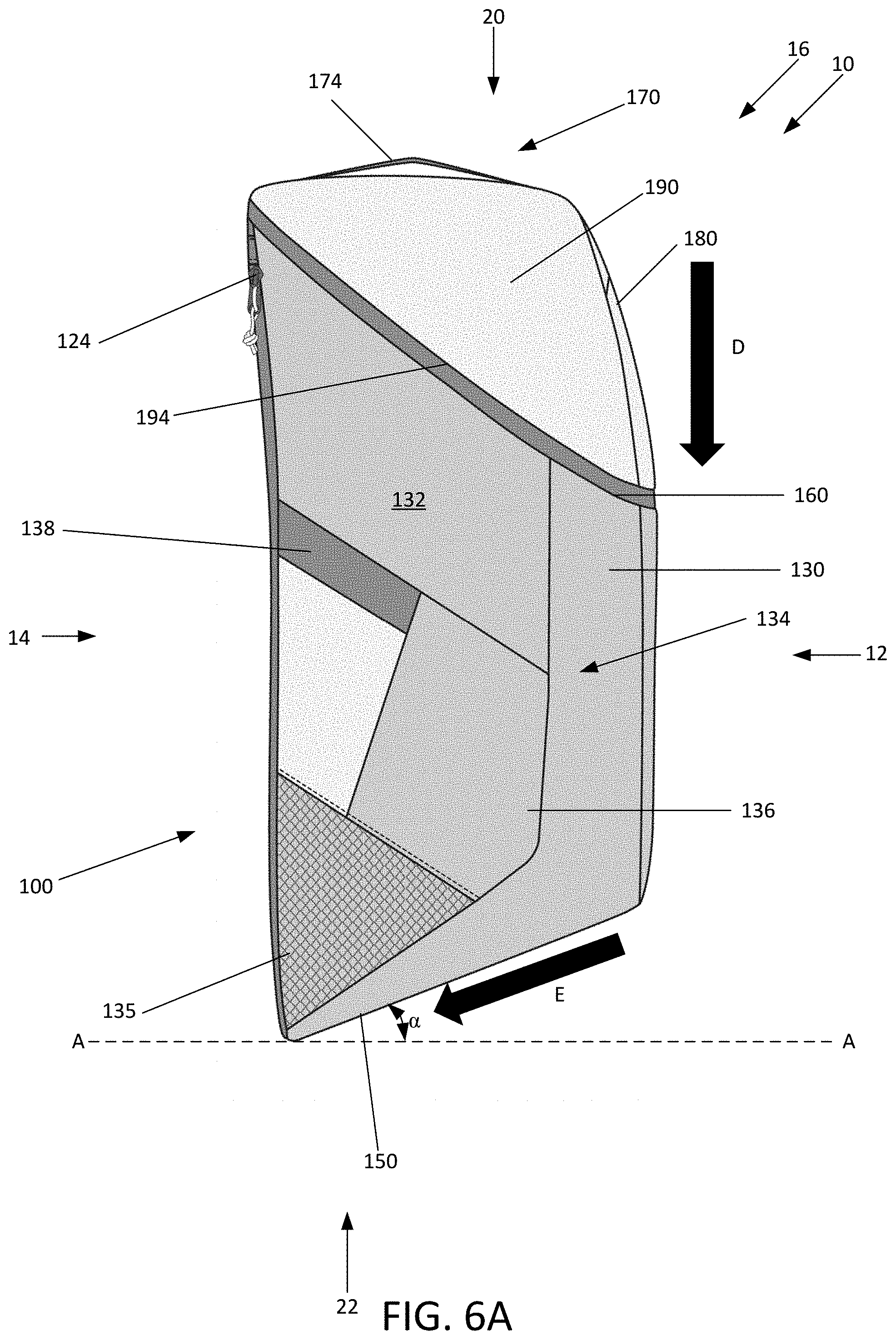
[0051] Turning to FIGS. 6A and 6B, the slanted or angled bottom panel 150 of the bag assembly 10 enables the bag assembly 10 to more effectively distribute the weight of the items or objects 600 disposed within the bag assembly 10 for a user wearing the bag assembly 10. While FIGS. 6A and 6B only illustrates the first embodiment of the bag assembly 10, the discussion of FIGS. 6A and 6B also pertains to the second and third embodiments 10', 10'' as their bottom panels 150', 150'', respectively, are also angled like that of the bottom panel 150 of the first embodiment of the bag assembly 10. Therefore, the second and third embodiments of the bag assembly 10', 10'' are configured to organize and distribute the weight of objects disposed within their respective cavities 300', 300'' like that described below for the first embodiment of the bag assembly 10.
[0052] As previously explained, because the bottom panel 150 of the main compartment 100 is slanted or angled, and because the bottom panel 150 forms the bottom of the interior cavity 300, the bottom of the interior cavity 300 is also angled with respect to a horizontal plane A-A. When placing an object 600 (e.g., books, laptops, etc.) within the interior cavity 300 of the main compartment 100, the object 600 is placed into the cavity 300 along direction D until the object 600 contacts the bottom panel 150, and more specifically, the interior surface 319 of the bottom surface 150. Because the bottom surface 150 is angled or slanted with respect to the horizontal plane A-A by an angle of a, once the object 600 contacts the bottom surface 150 within the interior cavity 300, the object 600 slides along the bottom surface 150 toward the rear panel 120. The angled bottom panel 150 retains the object 600 against the rear panel 120 as the bag assembly 10 is retained in the substantially vertical orientation (i.e., when worn on the back of the user as illustrated in FIG. 1E). By positioning and retaining the objects 600 against the rear panel 120 of the main compartment 100 of the bag assembly 10, heavy loads of the bag assembly 10 are disposed lower in the interior cavity 300 of the main compartment 100 of the bag assembly 10 and against the back of the user when the bag assembly 10 is worn by a user. Positioning heavy objects 600 with the bag assembly 10 low and towards the back of the user, reduces the likelihood that a user wearing the bag assembly 10 loaded with heavy objects 600 experiences back, neck, shoulder, and/or knee issues (i.e., pain, pulled muscles, etc.) because they are then able to maintain proper posture when wearing the bag assembly 10.
[0053] It is to be understood that terms such as "left," "right," "top," "bottom," "front," "rear," "side," "height," "length," "width," "upper," "lower," "interior," "exterior," "inner," "outer" and the like as may be used herein, merely describe points or portions of reference and do not limit the present invention to any particular orientation or configuration. Further, the term "exemplary" is used herein to describe an example or illustration. Any embodiment described herein as exemplary is not to be construed as a preferred or advantageous embodiment, but rather as one example or illustration of a possible embodiment of the invention.
[0054] Although the disclosed inventions are illustrated and described herein as embodied in one or more specific examples, it is nevertheless not intended to be limited to the details shown, since various modifications and structural changes may be made therein without departing from the scope of the inventions and within the scope and range of equivalents of the claims. In addition, various features from one of the embodiments may be incorporated into another of the embodiments. Accordingly, it is appropriate that the appended claims be construed broadly and in a manner consistent with the scope of the disclosure as set forth in the following claims.
* * * * *
D00000
D00001
D00002
D00003
D00004
D00005
D00006
D00007
D00008
D00009
D00010
D00011
D00012
D00013
D00014
D00015
D00016

XML
uspto.report is an independent third-party trademark research tool that is not affiliated, endorsed, or sponsored by the United States Patent and Trademark Office (USPTO) or any other governmental organization. The information provided by uspto.report is based on publicly available data at the time of writing and is intended for informational purposes only.
While we strive to provide accurate and up-to-date information, we do not guarantee the accuracy, completeness, reliability, or suitability of the information displayed on this site. The use of this site is at your own risk. Any reliance you place on such information is therefore strictly at your own risk.
All official trademark data, including owner information, should be verified by visiting the official USPTO website at www.uspto.gov. This site is not intended to replace professional legal advice and should not be used as a substitute for consulting with a legal professional who is knowledgeable about trademark law.