Hand-held Hair Styling Device
Kind Code
U.S. patent application number 15/758669 was filed with the patent office on 2020-08-06 for hand-held hair styling device. The applicant listed for this patent is WORLD WIDE DAILY HOLDING COMPANY LIMITED. Invention is credited to Chun Yuen To.
| Application Number | 20200245739 15/758669 |
| Document ID | 20200245739 / US20200245739 |
| Family ID | 1000004783488 |
| Filed Date | 2020-08-06 |
| Patent Application | download [pdf] |


View All Diagrams
| United States Patent Application | 20200245739 |
| Kind Code | A1 |
| To; Chun Yuen | August 6, 2020 |
HAND-HELD HAIR STYLING DEVICE
Abstract
A hand-held hair styling device has a body having a wider side between narrower sides. A rotatable base is mounted on the body for rotation relative to the body. The rotatable base has an exposed surface facing generally away from the body. An axis of rotation of the rotatable base extends substantially perpendicular to a longitudinal axis of the body. A plurality of hair styling elements extending generally away from the body are mounted on the exposed surface of the rotatable base for rotation relative to the body with the rotatable base. A method of styling hair includes rotating the rotatable base and the hair styling elements thereon while at least some of the hair styling elements are in contact with a person's hair.
| Inventors: | To; Chun Yuen; (New Territory, CN) | ||||||||||
| Applicant: |
|
||||||||||
|---|---|---|---|---|---|---|---|---|---|---|---|
| Family ID: | 1000004783488 | ||||||||||
| Appl. No.: | 15/758669 | ||||||||||
| Filed: | October 16, 2017 | ||||||||||
| PCT Filed: | October 16, 2017 | ||||||||||
| PCT NO: | PCT/CN2017/106352 | ||||||||||
| 371 Date: | March 8, 2018 |
| Current U.S. Class: | 1/1 |
| Current CPC Class: | A45D 2002/006 20130101; A45D 2/42 20130101; A45D 24/007 20130101; A45D 24/10 20130101; A45D 2/02 20130101 |
| International Class: | A45D 24/00 20060101 A45D024/00; A45D 2/02 20060101 A45D002/02; A45D 2/42 20060101 A45D002/42; A45D 24/10 20060101 A45D024/10 |
Foreign Application Data
| Date | Code | Application Number |
|---|---|---|
| Jun 7, 2017 | CN | PCT/CN2017/087427 |
Claims
1. A hand-held hair styling device, the hair styling device comprising: a body having a wider side between a pair of narrower sides on opposite sides of the wider side, the wider side of the body having a width that is wider than the narrower sides of the body; a rotatable base mounted between the narrower sides on the body for rotation relative to the body about an axis of rotation, the rotatable base having an exposed surface facing generally away from the body, the axis of rotation of the rotatable base extending substantially perpendicular to a longitudinal axis of the body; and a plurality of hair styling elements mounted on the exposed surface of the rotatable base for rotation relative to the body with the rotatable base, said plurality of hair styling elements extending generally away from the body.
2. A hand-held hair styling device as set forth in claim 1 further comprising a selectively activatable drive system for driving rotation of the rotatable base relative to the body.
3. A hand-held hair styling device as set forth in claim 2 wherein the selectively activatable drive system is configured to hold the rotatable base in a fixed position relative to the body when the selectively activatable drive system is not activated.
4. A hand-held hair styling device as set forth in claim 2 wherein the selectively activatable drive system comprises a set of gears and a manual actuator connected to the gears so that a user may drive rotation of the rotatable base by manually manipulating the manual actuator.
5. A hand-held hair styling device as set forth in claim 1 wherein at least some of the hair styling elements mounted on the rotatable base have a paddle-shaped configuration.
6. A hand-held hair styling device as set forth in claim 5 wherein said at least some of the hair styling elements having a paddle-shaped configuration have recesses formed in sides of the hair styling elements.
7. A hand-held hair styling device as set forth in claim 1 wherein each of the hair styling elements mounted on the rotatable base is spaced from each of the other hair styling elements.
8. A hand-held hair styling device as set forth in claim 1 wherein all of the hair styling elements are mounted on the rotatable base.
9. A hand-held hair styling device as set forth in claim 1 wherein the hair styling elements are substantially parallel to one another.
10. A hand-held hair styling device as set forth in claim 1 wherein the wider side of the body is substantially flat.
11. A hand-held hair styling device as set forth in claim 1 wherein the wider side of the body has a width that is at least about 2 inches.
12. A hand-held hair styling device as set forth in claim 1 wherein the body has a length that is at least about 4 inches.
13. A hand-held hair styling device as set forth in claim 1 wherein the rotatable base has a diameter of at least about 0.75 inches.
14. A method of styling a person's hair comprising: holding a body having a rotatable base thereon, the rotatable base being mounted on the body for rotation relative to the body and having a plurality of hair styling elements mounted thereon, the body having a wider side between a pair of narrower sides on opposite sides of the wider side, the rotatable base being mounted on the wider side; moving the body to place the hair styling elements in the person's hair; activating a selectively activatable drive system operably connected to the rotatable base to drive rotation of the rotatable base relative to the body about an axis of rotation and thereby rotate the rotatable base and the hair styling elements thereon while at least some of the hair styling elements are in contact with the person's hair, the axis of rotation of the rotatable base extending substantially perpendicular to a longitudinal axis of the body.
15. The method of claim 14 wherein activating the selectively activatable drive system comprises moving an actuator of the drive system from a first position to a second position.
16. The method of claim 15 further comprising removing the styling elements from contact with the person's hair while the actuator is in the second position.
17. The method of claim 16 further comprising biasing the drive system to the first position such that once the actuator is released the actuator automatically moves from the second position back to the first position.
18. A hand-held hair styling device, the hair styling device comprising: a body having a wider side between a pair of narrower sides on opposite sides of the wider side, the wider side of the body having a width that is wider than the narrower sides of the body; a rotatable base mounted between the narrower sides on the body for rotation relative to the body about an axis of rotation, the rotatable base having an exposed surface facing generally away from the body, the axis of rotation of the rotatable base extending substantially perpendicular to a longitudinal axis of the body; and at least one hair styling element mounted on the exposed surface of the rotatable base for rotation relative to the body with the rotatable base, said at least one hair styling element extending generally away from the body and having recesses therein opening radially outward from the axis of rotation of the rotatable base.
Description
CROSS REFERENCE TO RELATED APPLICATIONS
[0001] This application is a US National Stage Application of International Application No. PCT/CN2017/106352, filed Oct. 16, 2017 which claims the benefit of International Application No. PCT/CN2017/087427, filed Jun. 7, 2017, the entire contents of which are all hereby incorporated by reference.
FIELD OF INVENTION
[0002] The present invention relates generally to hand-held hair styling devices such as hair brushes and combs and more particularly to hand-held hair styling devices that are used to impart curls to a person's hair.
BACKGROUND
[0003] A conventional hand-held hair brush has a body and a handle extending from the body. A plurality of hair styling elements, such as bristles or teeth, extend away from the body of the brush. To use this conventional brush a person holds the handle in his or her hand and moves the brush so the hair styling elements pass through the hairs on a person's head.
[0004] A comb is similar to a brush. The hair styling elements on a comb are usually arranged in a more narrow configuration (e.g., a single row of teeth or a few closely spaced parallel rows of teeth) than the hair styling elements on a brush. However, there is no clear line between devices that are considered combs and devices that are considered brushes. Both combs and brushes operate by allowing a user to move a body carrying a plurality of hair styling elements that extend from the body so that the hair styling elements move through the hairs on a person's head.
[0005] The styling elements of the most common brushes and combs do not move relative to the body that carries them.
SUMMARY
[0006] One aspect of the invention is a hand-held hair styling device comprising a body having a wider side between a pair of narrower sides on opposite sides of the wider side. The wider side of the body has a width that is wider than the narrower sides of the body. A rotatable base is mounted between the narrower sides on the body for rotation relative to the body about an axis of rotation. The rotatable base has an exposed surface facing generally away from the body. The axis of rotation of the rotatable base extends substantially perpendicular to a longitudinal axis of the body. A plurality of hair styling elements are mounted on the exposed surface of the rotatable base for rotation relative to the body with the rotatable base. The plurality of hair styling elements extend generally away from the body.
[0007] Another aspect of the invention is a hand-held hair styling device having a body having a wider side between a pair of narrower sides on opposite sides of the wider side. The wider side of the body has a width that is wider than the narrower sides of the body. A plurality of rotatable bases are mounted between the narrower sides on the body for rotation relative to the body about axes of rotation. The rotatable bases each have an exposed surface facing generally away from the body. A plurality of hair styling elements are mounted on the exposed surface of each of the rotatable bases for rotation relative to the body with the respective rotatable base. The plurality of hair styling elements extend generally away from the body. A handle extends from the body in a direction that is substantially perpendicular to the axis of rotation of at least one of the rotatable bases.
[0008] Still another aspect of the invention is a hand-held hair styling device having a body that has a wider side between a pair of narrower sides on opposite sides of the wider side. The wider side of the body has a width that is wider than the narrower sides of the body. A plurality of rotatable bases are mounted between the narrower sides on the body for rotation relative to the body about axes of rotation. The rotatable bases each having an exposed surface facing generally away from the body. A plurality of hair styling elements are mounted on the exposed surface of each of the rotatable bases for rotation relative to the body with the respective rotatable base. The plurality of hair styling elements extend generally away from the body. Each of the hair styling elements mounted on the rotatable bases is spaced from each of the other hair styling elements.
[0009] Yet another aspect of the invention is a method of styling hair. The method includes holding a body having a rotatable base thereon. The rotatable base is mounted on the body for rotation relative to the body and has a plurality of hair styling elements mounted thereon. The body has a wider side between a pair of narrower sides on opposite sides of the wider side. The rotatable base is mounted on the wider side. The method includes moving the body to place the hair styling elements in the person's hair. Activating a selectively activatable drive system operably connected to the rotatable base to drive rotation of the rotatable base relative to the body about an axis of rotation and thereby rotate the rotatable base and the hair styling elements thereon while at least some of the hair styling elements are in contact with the person's hair. The axis of rotation of the rotatable base extends substantially perpendicular to a longitudinal axis of the body.
[0010] Still yet another aspect of the invention is a method of styling hair. The method includes holding a handle connected to a body having a plurality of rotatable bases thereon. Each of the rotatable bases is mounted on the body for rotation relative to the body and has a plurality of hair styling elements mounted thereon. The method includes moving the handle to place the hair styling elements in a person's hair. A selectively activatable drive system operably connected to the rotatable bases is activated to drive rotation of the rotatable bases relative to the body and thereby rotate the rotatable bases and the hair styling elements thereon while at least some of the hair styling elements are in contact with the person's hair.
[0011] In a further aspect of the present invention, a hand-held hair styling device generally comprises a body having a wider side between a pair of narrower sides on opposite sides of the wider side, the wider side of the body having a width that is wider than the narrower sides of the body. A rotatable base is mounted between the narrower sides on the body for rotation relative to the body about an axis of rotation. The rotatable base has an exposed surface facing generally away from the body, and the axis of rotation of the rotatable base extends substantially perpendicular to a longitudinal axis of the body. At least one hair styling element is mounted on the exposed surface of the rotatable base for rotation relative to the body with the rotatable base. The hair styling element extends generally away from the body and has recesses therein opening radially outward from the axis of rotation of the rotatable base.
[0012] Other objects and features will in part be apparent and in part pointed out hereinafter.
BRIEF DESCRIPTION OF THE DRAWINGS
[0013] FIG. 1 is a perspective of one embodiment of a hair styling device of the present invention;
[0014] FIGS. 2 and 3 are additional perspectives of the hair styling device illustrated in FIG. 1 taken from different vantage points;
[0015] FIG. 4 is a side elevation of the hair styling device illustrated in FIGS. 1-3;
[0016] FIG. 5 is a top plan of the hair styling device illustrated in FIGS. 1-4;
[0017] FIG. 6 is a bottom plan of the hair styling device illustrated in FIGS. 1-5;
[0018] FIG. 7 is an exploded perspective of the hair styling device illustrated in FIGS. 1-6;
[0019] FIG. 8 is a perspective of the hair styling device illustrated in FIGS. 1-7 with a portion of the device removed to show internal features;
[0020] FIG. 9 is a perspective of the hair styling device illustrated in FIGS. 1-8 similar to FIG. 8 but with an additional part of the device removed to show additional internal features;
[0021] FIG. 10. is a perspective of two different sets of interchangeable turntables having different styling elements configurations thereon for use with the hair styling device illustrated in FIGS. 1-9;
[0022] FIG. 11 is a perspective illustrating one method of using the device illustrated in FIGS. 1-9 to curl a person's hair;
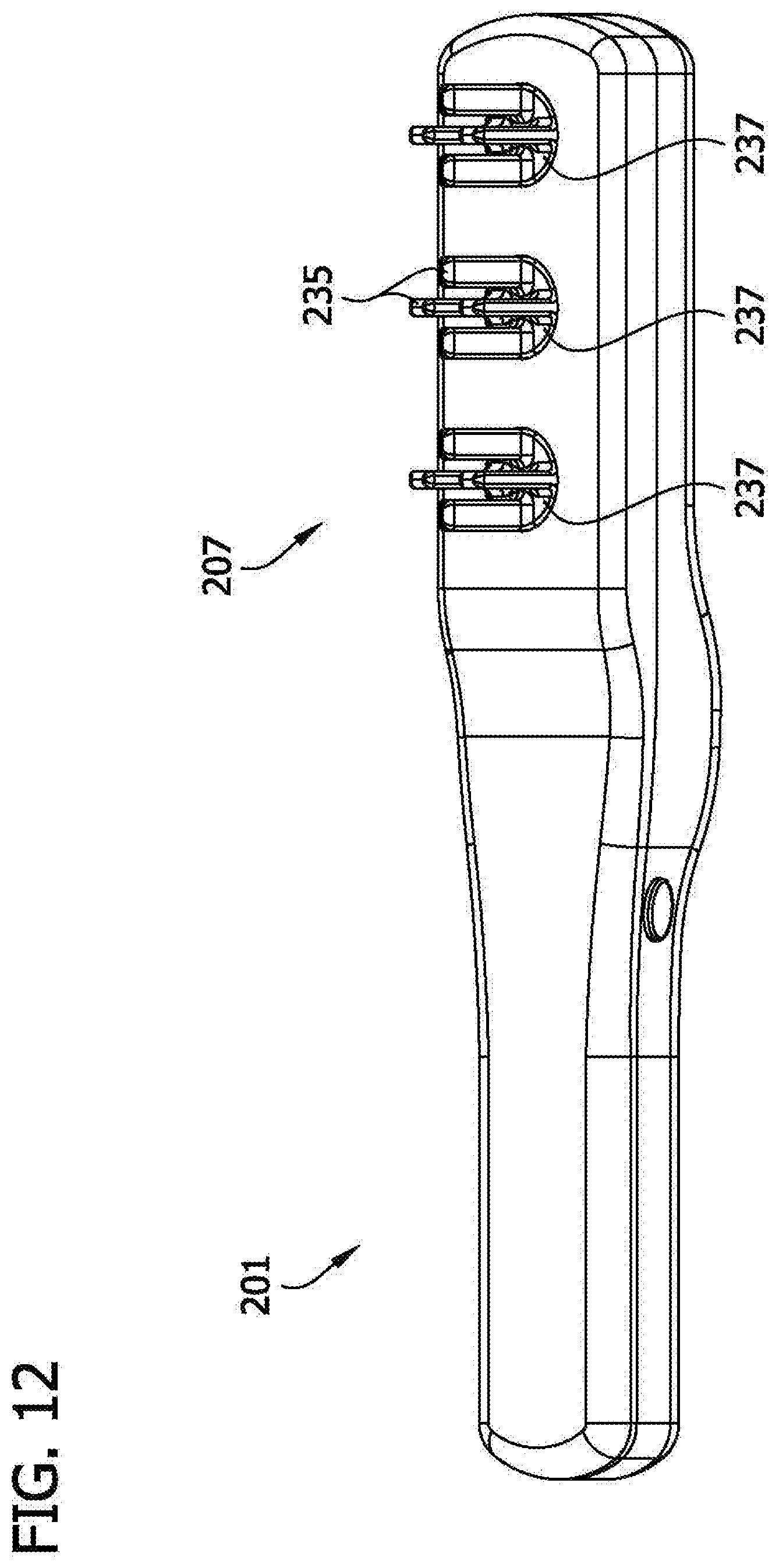
[0023] FIG. 12 is a perspective of another embodiment of a hair styling device of the present invention;
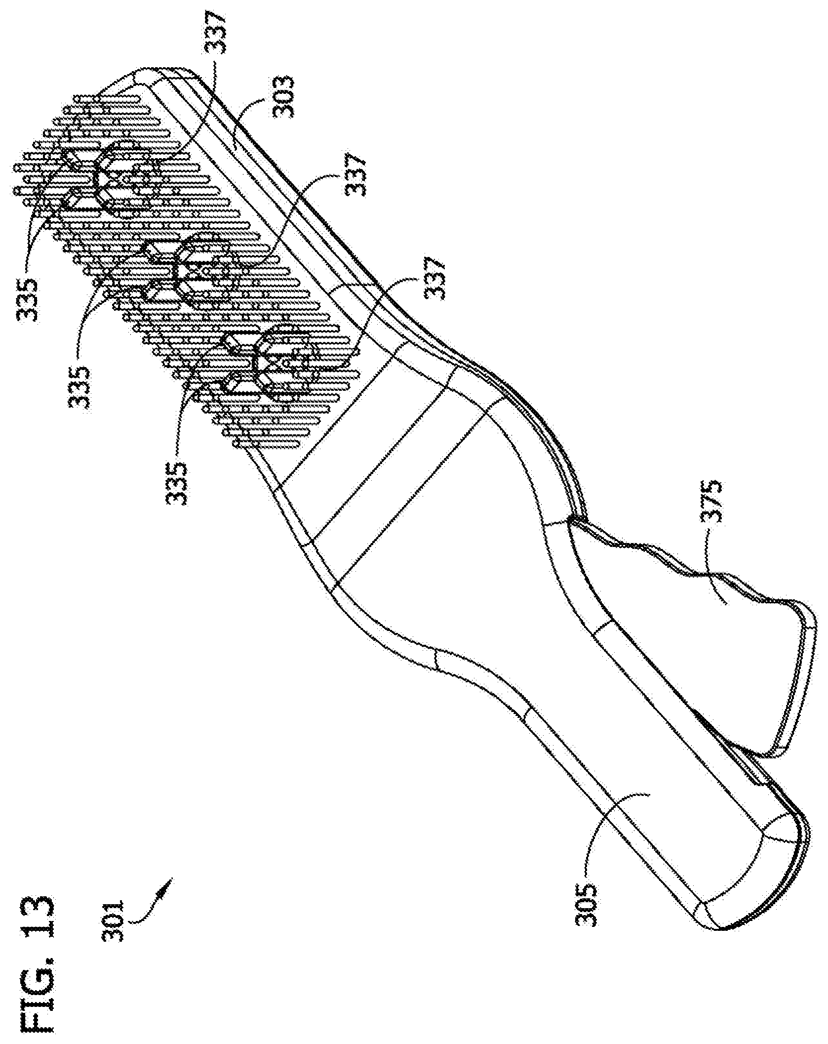
[0024] FIG. 13 is a perspective of another embodiment of a hair styling device of the present invention;
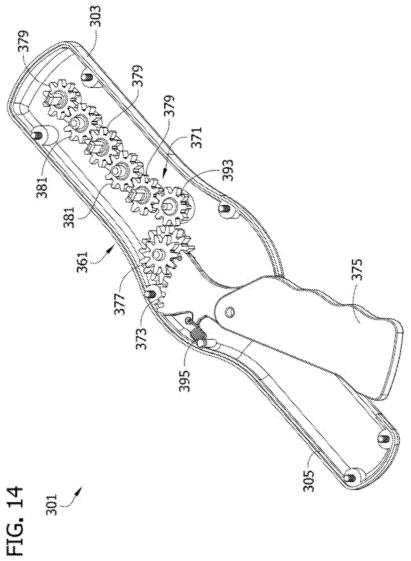
[0025] FIG. 14 is another perspective of the embodiment illustrated in FIG. 13 with portions of the device removed to show internal features;
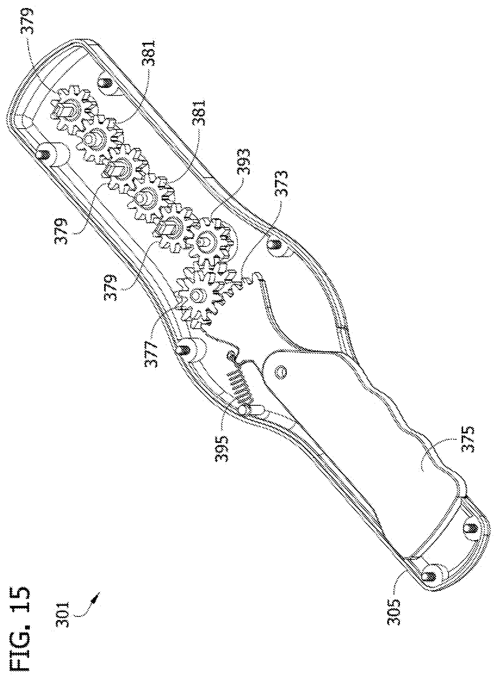
[0026] FIG. 15 is a perspective of the embodiment illustrated in FIGS. 13-14 showing a manually activatable drive lever in a depressed position;
[0027] FIG. 16 is a perspective of another embodiment of a hair styling device of the present invention;
[0028] FIG. 17 is another perspective of the embodiment illustrated in FIG. 16 with portions of the device removed to show internal features;
[0029] FIG. 17A is another perspective of the embodiment illustrated in FIG. 16 with portions of the device removed to show internal features;
[0030] FIG. 18 is a perspective of the embodiment illustrated in FIGS. 16-17 showing a manually activatable drive lever in a depressed position;
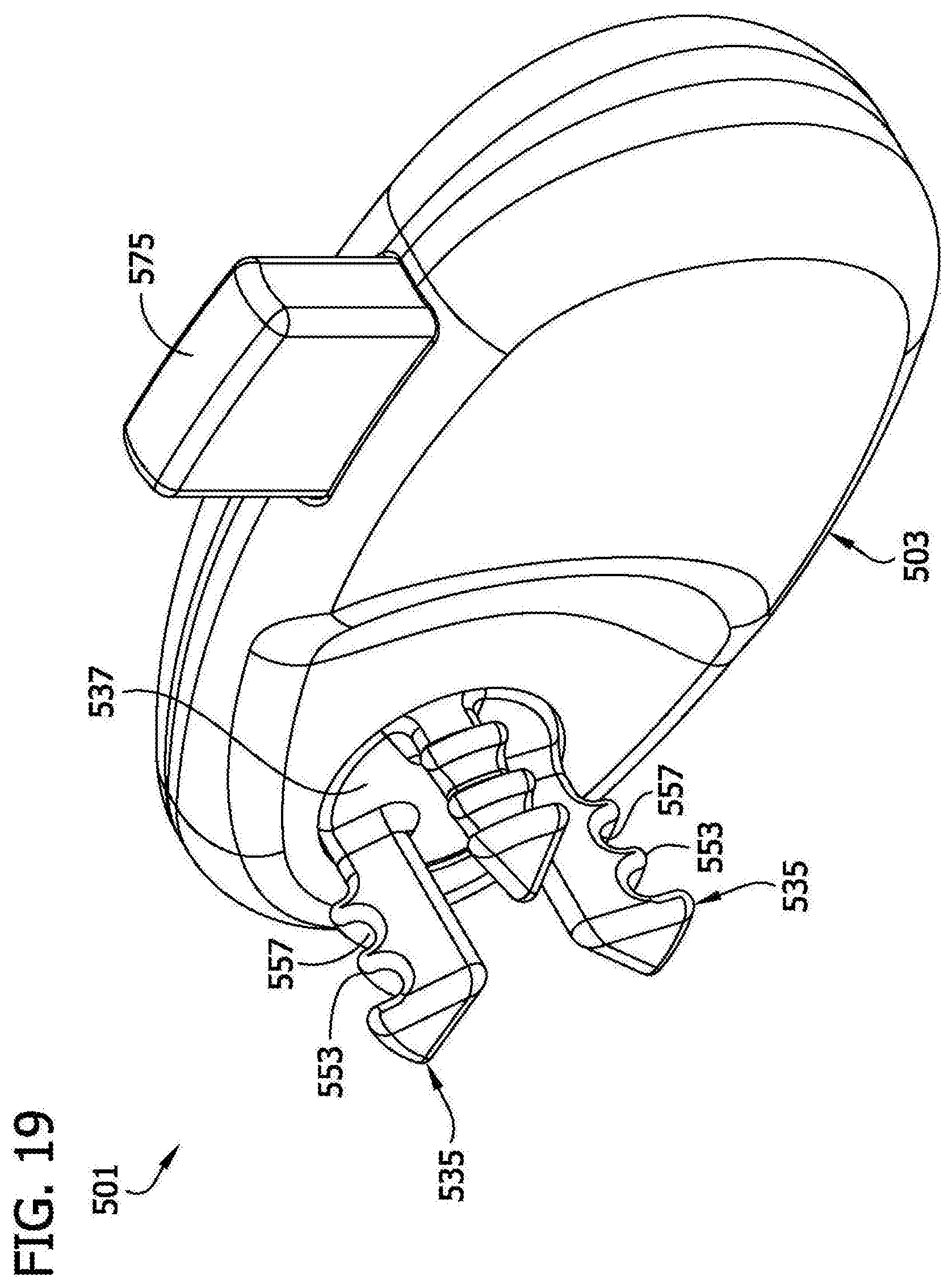
[0031] FIG. 19 is a perspective of another embodiment of a hair styling device of the present invention;
[0032] FIG. 20 is another perspective of the embodiment illustrated in FIG. 19 with portions of the device removed to show internal features;
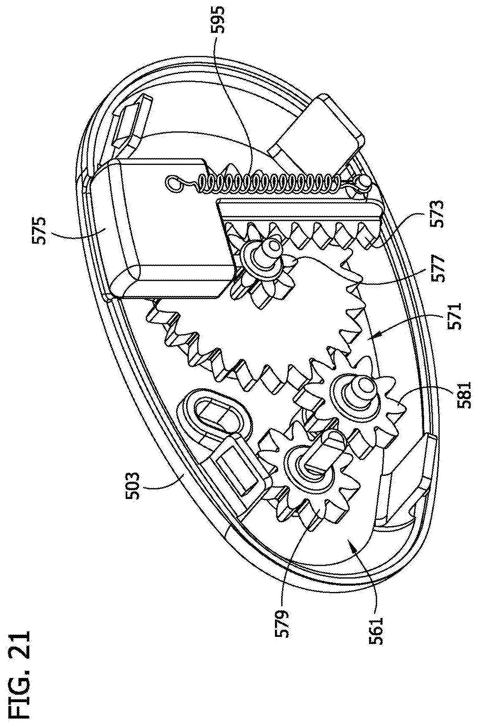
[0033] FIG. 21 is a perspective of the embodiment illustrated in FIGS. 19-20 showing a manually activatable drive lever in a depressed position;
[0034] FIG. 22 is a perspective of another embodiment of a hair styling device of the present invention;
[0035] FIG. 23 is another perspective of the embodiment illustrated in FIG. 22 with portions of the device removed to show internal features;
[0036] FIG. 24 is a perspective of the embodiment illustrated in FIGS. 22-23 showing a manually activatable drive lever in a depressed position
[0037] FIG. 25 is a perspective of another embodiment of a hair styling device of the present invention;
[0038] FIG. 26 is a perspective of another embodiment of a hair styling device of the present invention.
[0039] Corresponding reference characters indicate corresponding parts throughout the drawings.
DETAILED DESCRIPTION
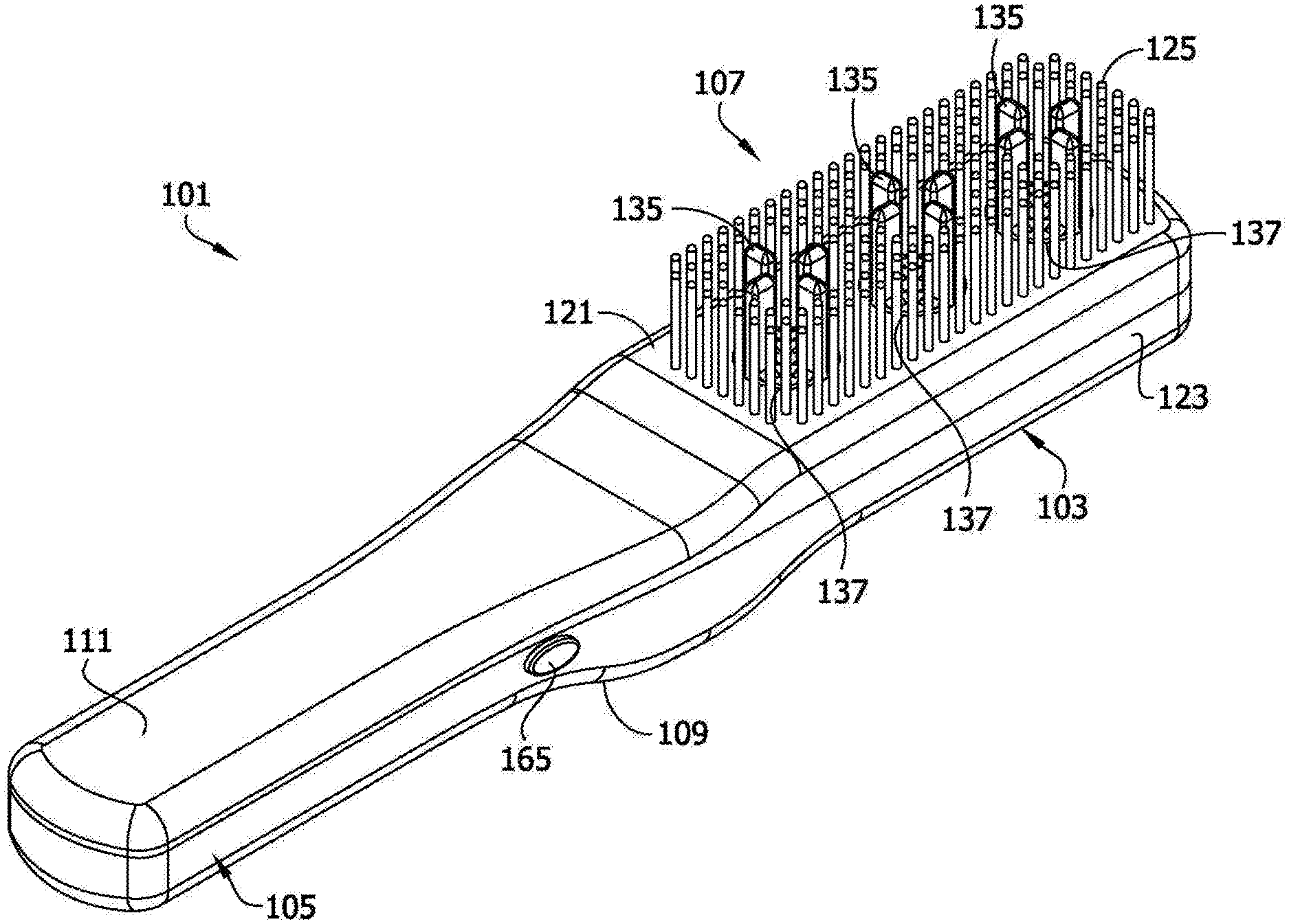
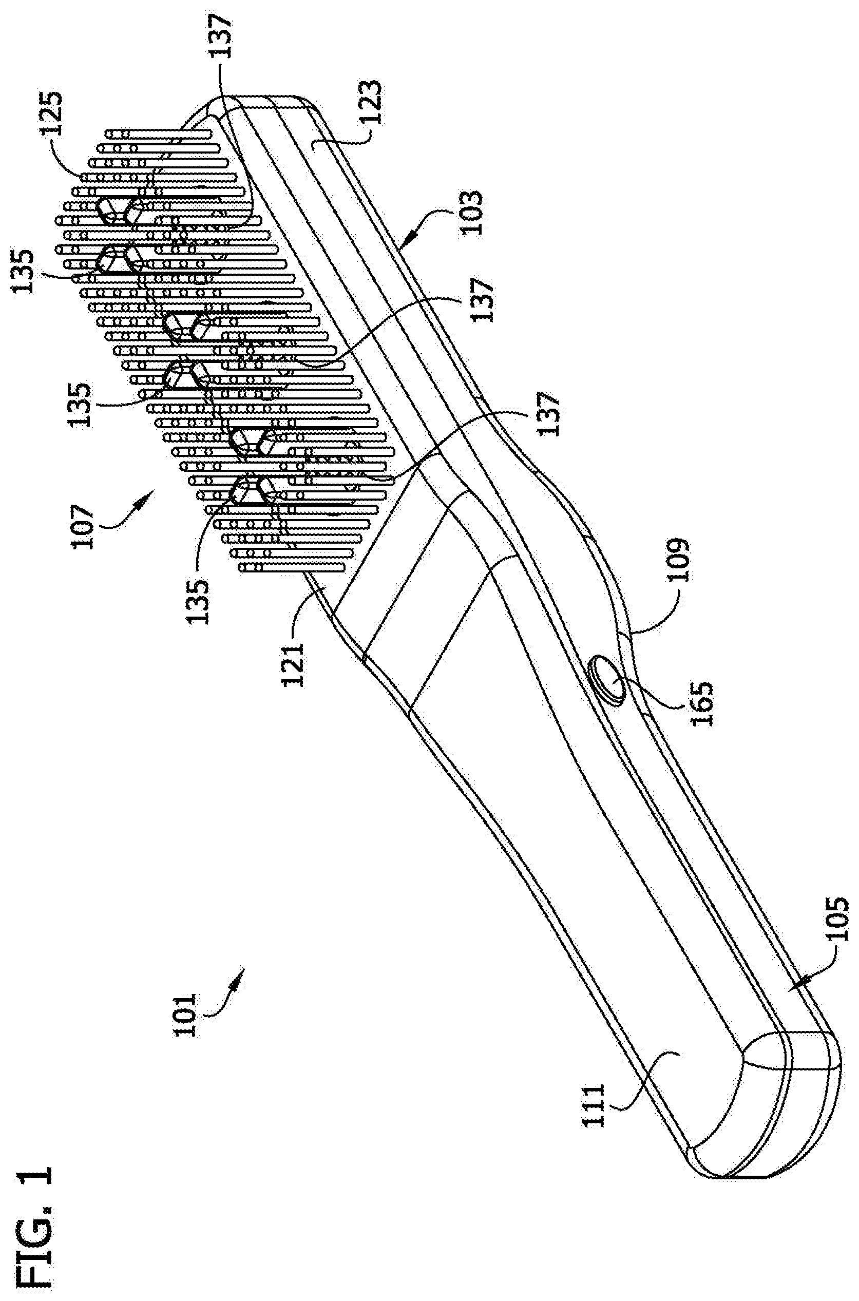
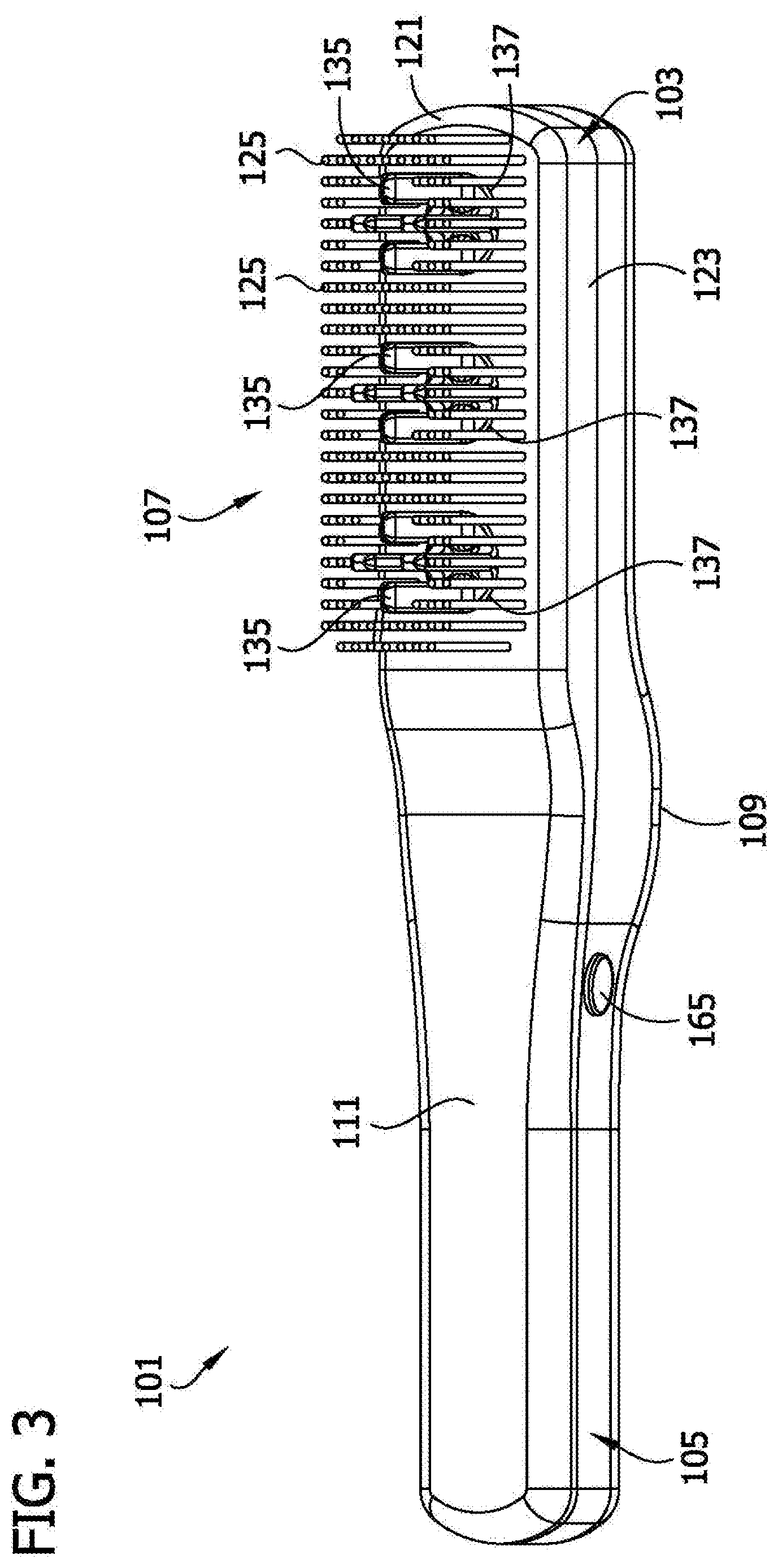
[0040] Referring now to the drawings, first to FIGS. 1-9, one embodiment of a hair styling device is generally designated 101. The device 101 can be used to brush hair in much the same way as a conventional hair brush. However, the device 101 can also be used to impart curls to a person's hair in a manner to be described in more detail below.
[0041] The device 101 has a body 103 and a handle 105 that extends from the body. The body 103 has one or more hair styling elements 107 secured thereto. The handle 105 is sized and shaped to fit in a person's hand so the person can move the body 103 and the hair styling elements 107 thereon relative to hair on that person's head or another person's head. The body 103 and handle 105 are suitably made of a moldable polymeric material, although other materials could be used instead. Referring to FIG. 7, the body 103 and handle 105 of the device 101 are each made of an upper shell 109 and a lower shell 111, which are so-named in reference to the orientation in FIG. 7. It is understood the lower shell 111 may be above the upper shell 109 and vice-versa, depending on how the device 101 is positioned. The upper shell 109 of the body 103 and handle 105 are suitably molded together as one-piece. Likewise, the lower shell 111 of the body 103 and handle 105 are also suitably molded together as one-piece. It is understood that the upper and lower shells 109, 111 can be made in greater or fewer pieces than in the illustrated embodiment and that the dividing lines between the multiple pieces of the shell can be varied. Also, if desired, the configuration of the shells can be varied from what is illustrated in FIGS. 1-9. The upper and lower shells 109, 111 are configured so they can be secured to one another (e.g., by screws 113 or other fasteners) to form the body 103 and handle 105. The body 103 and handle 105 suitably have a hollow interior space 115 for reasons that will become apparent.
[0042] Referring to FIGS. 4 and 5, the body 103 suitably has a wider side 121 extending between a pair of narrower sides 123 on opposite sides of the body 103. The narrower sides 123 are on opposite sides of the wider side 121. The width W1 of the wider side 121 is wider than the width W2 of the narrower sides 123. In the illustrated embodiment, the narrower sides 123 are about equal in width, but it is understood that this is not required. The width W1 of the wider side 121 of the body 103 is suitably at least about 2 inches. The length L1 of the body 103 is suitably at least about 4 inches. For purposes of measuring the length L1 of the body 103, the length L1 is defined as the distance between the end of the body opposite the handle 105 and the styling element 107 that is spaced farthest from that end. As illustrated in FIG. 1, the wider side 121 of the body 103 is suitably substantially flat.
[0043] A plurality of hair styling elements 107 are mounted on the wider side 121 of the body. In the embodiment illustrated in FIGS. 1-9, all of the styling elements 107 are on the wider side 121 of the body 103. Some of the hair styling elements 107 are suitably fixed styling elements 125 that are affixed to the body 103. For example, some or all of the fixed styling elements 125 are suitably affixed to the wider side 121 of the body 103. There are various ways to affix the fixed hair styling elements 125 to the body 103. Referring to FIG. 7, for instance, several or all of the fixed hair styling elements 125 are suitably mounted on a base 127 that supports multiple fixed hair styling elements. In the illustrated embodiment there are several bases 127, each of which carriers at least two fixed hair styling elements. The bases 127 are positioned inside the body 103 so that the fixed hair styling elements 125 extend through openings 129 in the lower shell 111. Thus, the distal ends of the fixed hair styling elements 125 extend away from the base 103 of the hair styling device 101. The bases 127 are captured inside the interior space 115 of the hair styling device 101 by the upper and lower shells 109, 111 and thereby retain the fixed hair styling elements on the base 103. Those skilled in the art of designing and/or manufacturing hair styling devices will be familiar with several other options for affixing fixed styling elements to the body of a hair styling device, any of which can be used instead of the arrangement in the illustrated embodiment.
[0044] At least some of the hair styling elements 107 are moveable hair styling elements 135 that are mounted on the body 103 for movement relative to the body. For example, the moveable hair styling elements 135 are suitably rotatable relative to the body 103. Referring to FIGS. 1, 3, 5, and 7, a plurality of turntables 137 (broadly, rotatable bases) are mounted on the body 103 for rotation of the turntables relative to the body about axes of rotation 139. Although the rotatable bases 137 in the illustrated embodiment are in the form of turntables, it is understood that the rotatable bases may have other shapes and configurations (e.g., dome-shaped or hemispherical) if desired. The turntables 137 are suitably mounted on the wider side 121 of the body 103 between its narrower sides 123. Referring to FIG. 5, the turntables 137 are suitably arranged in linear configuration extending generally along a longitudinal axis 143 of the body 103. For example, the turntables 137 are suitably mounted in series on the central longitudinal axis 143. Moreover, in the illustrated embodiment the central longitudinal axis 143 of the body 103 is aligned with the central longitudinal axis (also designated 143) of the handle 105 so the turntables 137 are also arranged in a linear configuration that extends along the longitudinal axis 143 of the handle. The turntables 137 are suitably mounted on the body 103 so the turntables have axes of rotation 139 that are substantially parallel to one another. In the illustrated embodiment the axes of rotation 139 of at least one of the turntables 137 (e.g., all of the turntables) is substantially perpendicular to the direction the handle 105 extends from the body 103. The axes of rotation 139 are suitably substantially perpendicular to the longitudinal axis 143 of the body 103 and handle 105.
[0045] The moveable hair styling elements 135 are mounted on the turntables 137 so the moveable hair styling elements move with the turntables. The turntables 137 are suitably received in openings 145 in the lower shell 111 so that some portions of the turntables are positioned inside the body 103. The turntables 137 also include an exposed surface 149 that is either positioned outside the body 103 or at least accessible from outside the body. The exposed surfaces 149 of the turntables 137 face generally away from the body 103. The moveable hair styling elements 135 are suitably secured to the exposed surfaces 149 of the turntables 137. The moveable styling elements 135 extend from the turntables 137 away from the body 103.
[0046] At least some of the moveable styling elements 135 are offset from the axes of rotation 143 of the turntable 137 that carries them. For example, in the embodiment illustrated in FIGS. 1-9, each of the moveable styling elements 135 is offset from the rotational axes 143 of the respective turntable 137. As illustrated in FIG. 5, some or all of the moveable styling elements 135 extend radially outward all the way to the outer perimeter of the respective turntable 137. The offset moveable styling elements 135 are positioned move in relatively wide circles when the turntables 137 are rotated due to their offset position. The turntables 137 suitably have a relatively large diameter D1, such as at least about 0.75 inches.
[0047] Referring to FIG. 4, the moveable styling elements 135 suitably extend about the same distance from the body 103 as the fixed styling elements 125. The distal ends of all of the hair styling elements suitably lie on the same plane P, as illustrated in FIG. 4. Alternatively, the distal ends of all of the hair styling elements may lie on a cylindrical or other smooth curved surface. When the hair styling device 101 is used to brush hair in the same way as a conventional brush, the fixed hair styling element 125 and the moveable hair styling elements 135 are both positioned to contact the hair and/or scalp and in the case the device 101 contacts the scalp there is not tendency for pressure to be concentrated in only a few of the hair styling elements 125, 135, as might occur if one set of hair styling elements is significantly longer than the other so that the ends do not all lie on the same plane or on a smoothly curved surface.
[0048] The configuration of the moveable styling elements 135 can vary within the broad scope of the invention. In the embodiment illustrated in FIGS. 1-9, at least some (e.g., all) of the moveable styling elements have a paddle-shaped configuration. Each of the paddle-shaped styling elements 135 has a broad side 151 oriented to face generally in the direction of rotation and narrow sides 153 oriented to face generally in a radial direction relative to the direction of rotation. The moveable hair styling elements 135 in this embodiment are suitably substantially parallel to one another. However, it is understood that the moveable styling elements may be oriented to angle toward or away from one another as they extend away from the base if desired. Also in this embodiment, each of the moveable styling elements 135 is spaced from each of the other moveable hair styling elements. This is in contrast to "tuft" style hair styling elements in which one or more bundles of styling elements are mounted in abutting relation to one another. However, it is understood that the moveable styling elements could include one or more tufts if desired.
[0049] The device 101 includes a drive system 161 for driving movement of the moveable styling elements 135, such as by driving rotation of the turntables 137. For example, the drive system 161 may be selectively activatable by user to rotate the turntables 137 and the moveable styling elements 135 thereon when desired. The drive system 161 is suitably also configured to hold the turntables 137 and the moveable styling elements 135 thereon stationary relative to the body 103 when desired.
[0050] Referring to FIGS. 7-9, the drive system 161 suitably includes a motor 163 (e.g., an electric motor) connected to the turntables 137 so the motor can rotate the turntables relative to the body 103. In the illustrated embodiment, the motor 163 is connected to the turntables 137 by a set of gears 171. The gears include a drive sprocket 173 mounted on the output shaft 175 of the motor 163 so the output shaft and drive sprocket rotate in unison. The drive sprocket 173 is in mesh with a speed changing gear 177, which is in mesh with the first of a set of turntable gears 179. The turntables 137 are mounted on the turntable gears 179 so the turntables rotate (e.g., in unison) with the turntable gears. In the illustrated embodiment, the speed changing gear 177 is configured to turn the first turntable gear 179 at a higher angular velocity than the angular velocity of the drive sprocket 173 and output shaft 175 of the motor 163. That is the speed changing gear 177 is configured to increase the speed as the power is transmitted from the motor to the turntables 137. However, the speed changing gear could be configured to reduce the speed of the turntable gear relative to the motor if desired.
[0051] Idler gears 181 are positioned between each of the turntable gears 179 so they are in mesh with the adjacent turntable gears. The gears 171 are thereby configured to rotate each of the turntables in the same direction. The gears 171 and drive system 161 are suitably configured to rotate each of the turntables 137 at substantially the same angular velocity. For example, the turntable gears 179 in the illustrated embodiment are all substantially equal in size and the idler gears 181 are also all substantially equal in size so that the turntable gears all rotate at about the same speed.
[0052] The turntables 137 can connected to the turntable gears 179 is various ways. In the illustrated embodiment, the turntables 137 are releasably secured to the turntable gears 177. Referring to FIGS. 7-9, for example, each of the turntable gears 177 has a spindle 185 extending along the rotational axis 139 (FIGS. 8 and 9). The spindles 185 are sized and shaped to be received in sockets 187 (FIG. 7) formed in the base of the turntables 137. The spindles 185 and sockets 187 each have a corresponding non-circular cross sectional shape so that the turntables 137 are rotationally locked with the spindles 185 and the turntable gears 179 when the spindles are in the sockets. The spindles 185 and sockets 187 are suitably dimensioned to result in a friction fit between the spindles and sockets that is strong enough to hold the turntables on the device 101 when in use for curling hair but weak enough that a user can pull the turntables 137 off the spindles 185 when desired. This facilitates exchanging one or more of the turntables 137 with a different turntable.
[0053] FIG. 10 illustrates two different sets of turntables 137, 137' that can be used interchangeably with the device 101. The first set of turntables 137 are the same turntables illustrated in FIGS. 1-9. The second set of turntables 137' is substantially identical to the first set of turntables 137 except that they have a different configuration of moveable hair styling elements 135'. Instead of paddle-shaped styling elements 135, the moveable styling elements 135' on the second set of turntables 137' are substantially cylindrical. Each of the substantially cylindrical styling elements 135' is spaced from each of the others. One of the styling elements 135' on each turntable 137' is located on the rotational axes 139. The other styling elements 135' are offset from the rotational axes 139. The styling elements 137's are all substantially parallel with one another and arranged in grid configuration (e.g., a 3.times.3 grid). Whenever a user would like to use a different type of moveable styling element with the device, he or she can pull the turntables off the device and replace them with a different set of turntables. Although there are only two types of turntables 137, 137' illustrated in FIG. 10, it is understood that there are numerous possible variations on the configuration of the moveable hair styling elements and that there could be a different set of turntables for any of the possible configurations that may be desired.
[0054] A switch 165 accessible on an external portion of the device 101 controls operation of the motor 163 and allows a user to selectively activate and deactivate the drive system 161. The switch 165 can be any suitable switch that is capable of selectively connecting and disconnecting the motor 163 to a power source (such as the internal batteries 167 in the illustrated embodiment).
[0055] For example, the switch 165 is suitably configured to energize the motor 163 and activate the drive system 161 when the switch is depressed by a user and de-energize the motor and turn off the drive system as soon as the user releases the switch. Thus, the user may activate and deactivate the drive system 161 with only one touch, with the duration of the touch defining the period that the drive system is active. IT may be desirable for some methods of using the device 101 to require active input by the user (such as requiring the user to continue pressing the switch 165) to continue operation of the drive system 161. For example, if a user is distracted while using the device and fails to maintain pressure on the switch 165, the device 101 automatically stops rotation of the turntables 137 and thereby minimizes the risk of tangled hair due to continued operation of the drive system while the user is distracted. Similarly, there is less risk of problems such as tangling hair that could result if a user tries to turn off the motor 163 off, but is delayed in doing so by a physical mistake (e.g., clumsiness) in the attempt to hit the switch 165.
[0056] The device 101 can be used in either of two modes: a fixed styling element mode and a moving (e.g., rotating) styling element mode. When used in fixed styling element mode, the device 101 operates in substantially the same way as a conventional hair brush. The user moves the handle 105 of the device 101 relative to the person's hair so that the fixed and moveable styling elements 125, 135 engage the person's hair and move relative to the person's hair (e.g., to untangle hair, distribute hair care products through the hair, straighten hair, curl hair, etc.)
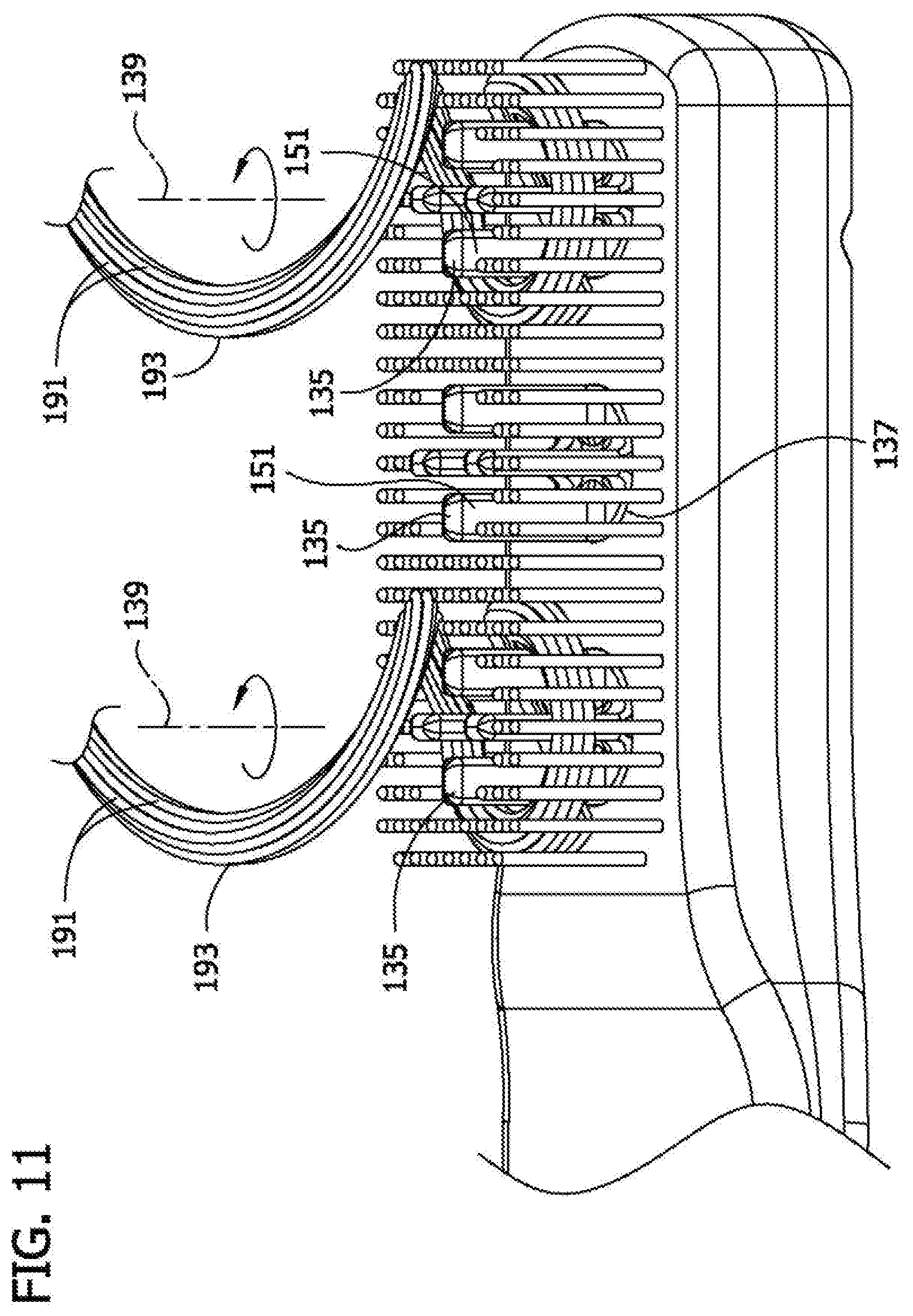
[0057] To use the device 101 in moving hair styling element mode, the user activates the drive system 161 (e.g., by pressing the switch 165) to drive movement of the moving styling elements 135. For example, referring to FIG. 11, the user suitably activates the drive system 161 to drive rotation of the turntables 137 relative to the body 103 and thereby rotate the turntables and the moveable hair styling elements 135 thereon while at least some of the hair styling elements are in contact with said person's hair. Various styling effects can be achieved using this method. For example, the rotating turntables 137 and moveable hair styling elements suitably form a twisted strand of hair 193 from a set of the hairs 191 on the person's head. In FIG. 11, the paddle-shaped moveable hair styling elements 135 are placed into contact with the strand of hair 193 at a location spaced from the person's head (e.g., near the end of the hairs in the strand). The wide faces 151 on the paddle-shaped styling elements 135 move the hairs in generally circular shape and thereby twist the strand of hair into a generally helical coil extending between the segment of the hairs in contact with the device and the person's head. The helical curvature applied to the strand 191 suitably has a central axis that is substantially parallel to the rotational axis 139 of the turntable 137 that has formed the helical coil in that strand. It is possible to form a first twisted strand using a first of the turntables while forming another twisted strand using another of the turntables. Because the device 101 has three turntables 137 it is also possible to twist three separate strands 193 of hair 191 into helical coils at the same time. However, it is not necessary to form multiple helical coils at the same time.
[0058] The method optionally includes holding the hairs 191 in the twisted strand for a period of time selected to impart a lasting helical curvature the strand. For example, the strand 193 may be sprayed with water or contacted with hairspray, mousse, gel, or other hair styling product while it is being held in the coiled shaped and held in the coiled shape while the water dries or the hair styling product dries and/or sets to help the hair hold the helical shape after the device 101 is removed from the hair.
[0059] The process can be repeated as much as desired to impart helical curls to additional strands 193 of hair 191.
[0060] This is just one example of how the device can be used to curl a person's hair. It is understood that the moveable hair styling elements can be used in different ways if desired.
[0061] FIG. 12 illustrated another embodiment of a hair styling device 201 of the present invention. This device 201 is substantially identical to the device 101 described above and illustrated in FIGS. 1-9, except that this device 201 does not have any fixed hair styling elements. Instead, all of the hair styling elements 207 are moveable hair styling elements 235 mounted on the turntables 237. The device 201 can be used to perform the same methods as the device 101 described above.
[0062] Another embodiment of a hair styling device, generally designated 301, is illustrated in FIGS. 13-15. This device 301 is substantially similar to the device 101 described above and illustrated in FIGS. 1-9, except that the drive system 161 described above has been replaced with a manually activatable drive system 361. There is no motor in this device 301. The drive system 361 has gears 371, which include turntable gears 379 and idler gears 381 corresponding to the turntable gears 179 and idler gears 181 described above. However, instead of a motor, the device 301 has a manual actuator 375, which in the illustrated embodiment is in the form of a lever mounted for pivoting movement so that one end of the lever extends outside the handle 305. A set of teeth 373 corresponding to a segment of a drive socket is formed on the opposite end of the lever 375. The teeth 373 are in mesh with a speed changing gear 377, which is in mesh with an auxiliary idler gear 393, which is in mesh with one of the turntable gears 379.
[0063] The lever 375 is moveable by a user between a first position (FIG. 14) in which lever protrudes farther from the handle 305 and a second position (FIG. 15) in which the lever protrudes less from the handle. A biasing member 395 (e.g., a spring) is positioned and arranged in the handle 305 to bias the lever 375 toward the first position. The lever 375 is positioned and arranged relative to the gears 371 so that movement of the lever between the first and second positions drives movement of the turntables 337 and the moveable styling elements 335 thereon through the gears. As was the case with the drive system 161 described above, the gears 371 are configured to drive each of the turntables 337 in the same direction and at about the same speed.
[0064] The device 301 can be used in substantially the same methods as described above in connection with the device 101 illustrated in FIGS. 1-9. However, in order to cause the moveable styling elements to move, a user manually activates the drive system 361 by manually manipulating the actuator 375 (e.g., lever) to move the actuator from the first position to the second position. The user then removes the device from the hair before releasing the actuator 375. Once the user releases the actuator 375 the biasing member 395 automatically moves the actuator back to the first position. This process may be repeated as many times as desired.
[0065] Another embodiment of a hair styling device, generally designated 401, is illustrated in FIGS. 16-18. This device 401 is similar to the device 301 described above and illustrated in FIGS. 13-15, except that body 403 has a generally oval shape and does not include an elongate handle extending from the body. Rather, the body 403 itself is intended to be grasped by a user for operating the device 401. Gripping surfaces 497 are also provided on the body 403 to facilitate grasping the body. As illustrated, the gripping surfaces 497 are a series of parallel channels in the body 403. However, it will be understood that the gripping surfaces may take on different forms, including without limitation, raised surfaces, bumps and high-friction material. As illustrated, the body 403 is formed in two halves that can be connected together. One half of the body has been removed in FIGS. 14 and 15 to show internal construction.
[0066] Additionally, only a single turntable 437 including a plurality of moveable styling elements 435 is mounted on the body 403. Similar to device 301, a drive system 461 has gears 471, which include a single turntable gear 479 and a single idler gear 481 corresponding to the turntable gear. A manual actuator 475, which in the illustrated embodiment is in the form of a lever mounted for pivoting movement so that one end of the lever extends outside the body 403. A set of teeth 473 corresponding to a segment of a drive socket is formed on the opposite end of the lever 475. The teeth 473 are in mesh with a speed changing gear 477, which is in mesh with the idler gear 481, which is in mesh with the turntable gear 479. The turntable 437 is connected to the turntable gear 479 for conjoint rotation with the turntable. In the illustrated embodiment, each moveable styling element 435 has a paddle shape with a pair of recesses 457 formed in a narrow side 453 of the element. The recesses 457 face radially outwardly of the hair styling element 435 and receive and retain many strands of hair during use, similar to the teeth of a comb. However, the configuration of the moveable styling elements 435 can vary within the broad scope of the invention. The overall size of body 403 is similar to that of body 103 such that a width of a wider side of the body 403 is suitably at least about 2 inches, and a length of the body 403 is suitably at least about 4 inches.
[0067] As described above for device 301, the lever 475 is moveable by a user between a first position (FIGS. 17 and 17A) and a second position (FIG. 18). A biasing member 495 (e.g., a spring) is positioned and arranged in the body 403 to bias the lever 475 toward the first position (FIG. 17A). The lever 475 is positioned and arranged relative to the gears 471 so that movement of the lever between the first and second positions drives movement of the turntable 437 and the moveable styling elements 435 thereon through the gears.
[0068] In order to cause the moveable styling element to move, a user manually activates the drive system 461 by manually manipulating the actuator 475 (e.g., lever) to move the actuator from the first position to the second position. The size of the gear 477 in relation to the gears 481 and 479 causes the causes the turntable 437 and hair styling elements mounted thereon to turn more rapidly through a greater angle of rotation than the gear 477. The user then removes the device from the hair before releasing the actuator 475. Once the user releases the actuator 475 the biasing member 495 automatically moves the actuator back to the first position. This process may be repeated as many times as desired.
[0069] Another embodiment of a hair styling device, generally designated 501, is illustrated in FIGS. 19-21. This device 501 is substantially similar to the device 401 described above and illustrated in FIGS. 16-18, except that actuator 575 comprises a depressible button on a side of body 503. The actuator 575 can be moved along a line, back and forth to actuate rotation of the hair styling elements 535. The body 503, including particularly the portion of the body removed in FIGS. 17 and 18, includes structure for guiding the movement of the actuator 575 along its linear, reciprocating path. The spring 595 is attached to and end of the actuator 575 opposite the portion forming the button. The other end of the spring 595 is attached to a post (not shown) on a portion of the body 503 which is removed in FIGS. 20 and 21. The post provides a fixed point against which the spring 595 acts to move the actuator 575. Additionally, each moveable styling element 535 is paddle-shaped with a generally triangular cross section. Recesses 557 are formed in sides 553 of the styling elements. In one embodiment, hair styling device 401 of the previous embodiment may use an actuator assembly including actuator 575 disclosed for device 501 of the current embodiment without departing from the scope of the invention.
[0070] Another embodiment of a hair styling device, generally designated 601, is illustrated in FIGS. 22-24. This device 601 is substantially similar to the device 501 described above and illustrated in FIGS. 19-21, except that actuator 675 comprises a depressible button on a bottom of body 603. Moreover, the actuator 675 is generally flush with the surface of the body 603 when not depressed as shown in FIGS. 22 and 23. As may be seen in FIGS. 23 and 24, the body 603 includes guide walls that guide the movement of the actuator 675. Similar guide walls (not shown) are also present on the portion of the body 603 removed from FIGS. 23 and 24. In this embodiment, two springs 695 are employed. The springs 695 are attached at ends of respective legs of the actuator 675. The other ends of the springs 695 are attached to posts (not shown) on the part of the body 603 that has been removed in FIGS. 23 and 24. One of the legs is formed with teeth 673 that engage the drive system 661. Additionally, each moveable styling element 635 is paddle-shaped and has a generally rectangular cross section. The hair styling elements 635 do not have recesses, but it will be understood that such recesses could be used.
[0071] Another embodiment of a hair styling device, generally designated 701, is illustrated in FIG. 25. This device 701 is substantially similar to the device 501 described above and illustrated in FIGS. 19-21, except a single styling element 735 is mounted on turntable 737. The styling element 735 has a triangular prism shape. Sides 759 of the styling element 735 are concave. Recesses 757 are formed in edges 753 of the styling element 735. The recesses 757 open radially outward from the hair styling element. The recesses 757 are arranged in groups. Different groups of recesses open in a different radial direction about the axis of rotation of the rotatable base 737.
[0072] Another embodiment of a hair styling device, generally designated 801, is illustrated in FIG. 26. This device 801 is substantially similar to the device 501 described above and illustrated in FIGS. 19-21, except styling elements 835 have a generally hexagonal prism shape. Recesses 857 are formed in sides 853 of the styling elements 835.
[0073] In view of the foregoing, it will be understood that the following has been developed:
[0074] A1. A hand-held hair styling device, the hair styling device comprising:
[0075] a body having a wider side between a pair of narrower sides on opposite sides of the wider side, the wide side of the body having a width that is wider than the narrower sides of the body;
[0076] a plurality of rotatable bases mounted between the narrower sides on the body for rotation relative to the body about axes of rotation, the rotatable bases each having an exposed surface facing generally away from the body;
[0077] a plurality of hair styling elements mounted on the exposed surface of each of the rotatable bases for rotation relative to the body with the respective rotatable base, said plurality of hair styling elements extending generally away from the body; and
[0078] a handle extending from the body in a direction that is substantially perpendicular to the axis of rotation of at least one of the rotatable bases.
[0079] A2. A hand-held hair styling device as set forth in A1 further comprising a selectively activatable drive system for driving rotation of the rotatable bases relative to the body.
[0080] A3. A hand-held hair styling device as set forth in claim A2 wherein the selectively activatable drive system is configured to hold the rotatable bases in a fixed position relative to the body when the selectively activatable drive system is not activated.
[0081] A4. A hand-held hair styling device as set forth in A2 wherein the selectively activatable drive system comprises a set of gears and a manual actuator connected to the gears so that a user may drive rotation of the rotatable bases by manually manipulating the manual actuator.
[0082] A5. A hand-held hair styling device as set forth in A2 wherein the selectively activatable drive system comprises an electric motor connected to the rotatable bases so the motor can rotate the rotatable bases relative to the body and a switch configured to selectively turn the electric motor on and off.
[0083] A6. A hand-held hair styling device as set forth in A1 further comprising a plurality of hair styling elements affixed to the wider side of the body.
[0084] A7. A hand-held hair styling device as set forth in A1 wherein at least some of the hair styling elements mounted on the rotatable bases have a paddle-shaped configuration.
[0085] A8. A hand-held hair styling device as set forth in A1 wherein each of the hair styling elements mounted on the rotatable bases is spaced from each of the other hair styling elements.
[0086] A9. A hand-held hair styling device as set forth in A1 wherein all of the hair styling elements are mounted on the rotatable bases.
[0087] A10. A hand-held hair styling device as set forth in A1 wherein the body has a longitudinal axis and the rotatable bases are mounted on the body in a linear configuration extending generally along the longitudinal axis of the body.
[0088] A11. A hand-held hair styling device as set forth in A1 wherein the rotatable bases have rotational axes that are substantially parallel to one another.
[0089] A12. A hand-held hair styling device as set forth in A1 wherein the hair styling elements are substantially parallel to one another.
[0090] A13. A hand-held hair styling device as set forth in A1 wherein the wider side of the body is substantially flat.
[0091] A14. A hand-held hair styling device as set forth in A1 wherein the wider side of the body has a width that is at least about 2 inches.
[0092] A15. A hand-held hair styling device as set forth in A1 wherein the body has a length that is at least about 3 inches.
[0093] A16. A hand-held hair styling device as set forth in A1 wherein at least one of the rotatable bases has a diameter that is at least about 2 inches in length.
[0094] A17. A hand-held hair styling device, the hair styling device comprising:
[0095] a body having a wider side between a pair of narrower sides on opposite sides of the wider side, the wide side of the body having a width that is wider than the narrower sides of the body;
[0096] a plurality of rotatable bases mounted between the narrower sides on the body for rotation relative to the body about axes of rotation, the rotatable bases each having an exposed surface facing generally away from the body; and
[0097] a plurality of hair styling elements mounted on the exposed surface of each of the rotatable bases for rotation relative to the body with the respective rotatable base, said plurality of hair styling elements extending generally away from body;
[0098] wherein each of the hair styling elements mounted on the rotatable bases is spaced from each of the other hair styling elements.
[0099] A18. A hand-held hair styling device as set forth in A17 wherein at least some of the hair styling elements mounted on the rotatable bases have a paddle-shaped configuration.
[0100] A19. A hand-held hair styling device as set forth in A17 wherein the body has a longitudinal axis and the rotatable bases are mounted on the body in a linear configuration extending generally along the longitudinal axis of the body.
[0101] A20. A hand-held hair styling device as set forth in A17 wherein the rotatable bases have rotational axes that are substantially parallel to one another.
[0102] A21. A hand-held hair styling device as set forth in A17 wherein the wider side of the body has a width that is at least about 2 inches.
[0103] A22. A hand-held hair styling device as set forth in A17 wherein the body has a length that is at least about 3 inches.
[0104] A23. A hand-held hair styling device as set forth in A17 wherein at least one of the rotatable bases has a diameter that is at least about 2 inches in length.
[0105] A24. A method of styling hair, the method comprising:
[0106] holding a handle connected to a body having a plurality of rotatable bases thereon, wherein each of the rotatable bases is mounted on the body for rotation relative to the body and has a plurality of hair styling elements mounted thereon;
[0107] moving the handle to place the hair styling elements in a person's hair; and
[0108] selectively activating a drive system operably connected to the rotatable bases to drive rotation of the rotatable bases relative to the body and thereby rotating the rotatable bases and the hair styling elements thereon while at least some of the hair styling elements are in contact with said person's hair.
[0109] A25. A method as set forth in A24 wherein rotating the rotatable bases and the hair styling elements thereon while at least some of the hair styling elements are in contact with said person's hair comprises forming a twisted strand of hair from a set of hairs on the person's head.
[0110] A26. A method as set forth in A25 further comprising holding the hairs in said set in the twisted strand for a period of time selected to impart a helical curvature to at least some of the hairs in said set.
[0111] A27. A method as set forth in A24 wherein rotating the rotatable bases and the hair styling elements thereon while at least some of the hair styling elements are in contact with said person's hair comprises imparting a helical curvature to at least some of the hair on the person's head.
[0112] A28. A method as set forth in A27 wherein the helical curvature applied to the hair has a central axis that is substantially parallel to an axis of rotation of at least one of the rotatable bases.
[0113] A29. A method as set forth in A24 wherein rotating the rotatable bases and the hair styling elements thereon while at least some of the hair styling elements are in contact with said person's hair comprises forming a first twisted strand of hair from a first set of hairs on the person's head using a first of the rotatable bases while forming a second twisted strand of hair from a second set of hairs on the person's head using a second of the rotatable bases.
[0114] When introducing elements of the present invention or the preferred embodiment(s) thereof, the articles "a", "an", "the" and "said" are intended to mean that there are one or more of the elements. The terms "comprising", "including" and "having" are intended to be inclusive and mean that there may be additional elements other than the listed elements.
[0115] As various changes could be made in the above apparatuses, systems, and methods without departing from the scope of the invention, it is intended that all matter contained in the above description and shown in the accompanying drawings shall be interpreted as illustrative and not in a limiting sense.
* * * * *
D00000
D00001
D00002
D00003
D00004
D00005
D00006
D00007
D00008
D00009
D00010
D00011
D00012
D00013
D00014
D00015
D00016

D00017

D00018

D00019

D00020
D00021

D00022
D00023

D00024

D00025

D00026

D00027

XML
uspto.report is an independent third-party trademark research tool that is not affiliated, endorsed, or sponsored by the United States Patent and Trademark Office (USPTO) or any other governmental organization. The information provided by uspto.report is based on publicly available data at the time of writing and is intended for informational purposes only.
While we strive to provide accurate and up-to-date information, we do not guarantee the accuracy, completeness, reliability, or suitability of the information displayed on this site. The use of this site is at your own risk. Any reliance you place on such information is therefore strictly at your own risk.
All official trademark data, including owner information, should be verified by visiting the official USPTO website at www.uspto.gov. This site is not intended to replace professional legal advice and should not be used as a substitute for consulting with a legal professional who is knowledgeable about trademark law.