Terminal Device And Method Of Controlling The Same
Kind Code
U.S. patent application number 16/561941 was filed with the patent office on 2020-07-30 for terminal device and method of controlling the same. This patent application is currently assigned to ORDOS YUANSHENG OPTOELECTRONICS CO., LTD.. The applicant listed for this patent is ORDOS YUANSHENG OPTOELECTRONICS CO., LTD. BOE TECHNOLOGY GROUP CO., LTD.. Invention is credited to Jigang SUN, Wei SUN, Jieqiong WANG, Shaolei ZONG.
| Application Number | 20200245120 16/561941 |
| Document ID | 20200245120 / US20200245120 |
| Family ID | 1000004334514 |
| Filed Date | 2020-07-30 |
| Patent Application | download [pdf] |


| United States Patent Application | 20200245120 |
| Kind Code | A1 |
| ZONG; Shaolei ; et al. | July 30, 2020 |
TERMINAL DEVICE AND METHOD OF CONTROLLING THE SAME
Abstract
A terminal device and a method of controlling the terminal device are provided. The terminal device includes: a terminal body; a pressure sensor arranged at a lateral side of the terminal body; and an execution circuit connected to an output end of the pressure sensor and configured to execute a predetermined operation when a pressure detected by the pressure sensor is not smaller than a predetermined pressure threshold.
| Inventors: | ZONG; Shaolei; (Beijing, CN) ; SUN; Wei; (Beijing, CN) ; WANG; Jieqiong; (Beijing, CN) ; SUN; Jigang; (Beijing, CN) | ||||||||||
| Applicant: |
|
||||||||||
|---|---|---|---|---|---|---|---|---|---|---|---|
| Assignee: | ORDOS YUANSHENG OPTOELECTRONICS
CO., LTD. Ordos CN BOE TECHNOLOGY GROUP CO., LTD. Beijing CN |
||||||||||
| Family ID: | 1000004334514 | ||||||||||
| Appl. No.: | 16/561941 | ||||||||||
| Filed: | September 5, 2019 |
| Current U.S. Class: | 1/1 |
| Current CPC Class: | H04W 4/90 20180201; G08B 6/00 20130101; H04M 1/0202 20130101; H04M 2250/12 20130101 |
| International Class: | H04W 4/90 20060101 H04W004/90; H04M 1/02 20060101 H04M001/02; G08B 6/00 20060101 G08B006/00 |
Foreign Application Data
| Date | Code | Application Number |
|---|---|---|
| Jan 25, 2019 | CN | 201910073445.5 |
Claims
1. A terminal device, comprising: a terminal body; a pressure sensor arranged at a lateral side of the terminal body; and an execution circuit connected to an output end of the pressure sensor and configured to execute a predetermined operation when a pressure detected by the pressure sensor is not smaller than a predetermined pressure threshold.
2. The terminal device according to claim 1, wherein there are at least two pressure sensors, and at least one pressure sensor is arranged at each of two opposite lateral sides of the terminal body.
3. The terminal device according to claim 2, wherein the execution circuit is further configured to execute the predetermined operation when the pressure detected by at least one pressure sensor at each of the two opposite lateral sides of the terminal body is not smaller than the predetermined pressure threshold.
4. The terminal device according to claim 1, further comprising a communication circuit connected to the execution circuit, wherein the execution circuit is further configured to control the communication circuit to send an alarm signal, and the communication circuit is configured to make an emergency call and/or send alarm information.
5. The terminal device according to claim 4, further comprising a feedback circuit connected to the communication circuit and the execution circuit, and configured to control the communication circuit to send the alarm signal continuously when the alarm signal has been sent but no input for interrupting the alarm signal has been detected.
6. The terminal device according to claim 4, further comprising a vibration circuit configured to send a vibration prompt signal after the communication circuit has sent the alarm signal.
7. The terminal device according to claim 1, wherein the pressure sensor comprises four strain gauges connected in an end-to-end manner to form a bridge, a connection end is formed between two adjacent strain gauges, the bridge comprises four connection ends, the four connection ends comprise a first connection end, a second connection end, a third connection end and a fourth connection end, the first connection end and the third connection end are connected to two ends of an excitation power source respectively, and the second connection end and the fourth connection end are connected to two output ends of the pressure sensor respectively.
8. The terminal device according to claim 1, further comprising a signal amplification circuit, an input end of which is connected to the output end of the pressure sensor, and an output end of which is connected to an input end of the execution circuit.
9. The terminal device according to claim 2, wherein the pressure sensor comprises four strain gauges connected in an end-to-end manner to form a bridge, a connection end is formed between two adjacent strain gauges, the bridge comprises four connection ends, the four connection ends comprise a first connection end, a second connection end, a third connection end and a fourth connection end, the first connection end and the third connection end are connected to two ends of an excitation power source respectively, and the second connection end and the fourth connection end are connected to two output ends of the pressure sensor respectively.
10. The terminal device according to claim 2, further comprising a signal amplification circuit, an input end of which is connected to the output end of the pressure sensor, and an output end of which is connected to an input end of the execution circuit.
11. The terminal device according to claim 8, wherein the signal amplification circuit comprises a first operational amplifier, a second operational amplifier, a third operational amplifier, a first resistor, a second resistor, a third resistor, a fourth resistor, a fifth resistor, a sixth resistor and a variable resistor, wherein an input end of the signal amplification circuit is connected to an in-phase input end of the first operational amplifier and an in-phase input end of the second operational amplifier, an output end of the first operational amplifier is connected to a first end of the first resistor and a first end of the second resistor, a reversed-phase input end of the first operational amplifier is connected to a second end of the second resistor, an output end of the second operational amplifier is connected to a first end of the third resistor and a first end of the fourth resistor, a reversed-phase input end of the second operational amplifier is connected to a second end of the fourth resistor, a first end of the variable resistor is connected to the second end of the second resistor, a second end of the variable resistor is connected to the second end of the fourth resistor, a second end of the first resistor forms a first output end of the signal amplification circuit, the second end of the first resistor is further connected to a first end of the fifth resistor, a second end of the fifth resistor is connected to a ground line, a second end of the third resistor forms a second output end of the signal amplification circuit, the second end of the third resistor is further connected to a first end of the sixth resistor, an in-phase input end of the third operational amplifier is connected to the first output end of the signal amplification circuit, a reversed-phase input end of the third operational amplifier is connected to the second output end of the signal amplification circuit, and an output end of the third operational amplifier is connected to a third output end of the signal amplification circuit.
12. A method of controlling the terminal device according to claim 1, comprising executing a predetermined operation when a pressure detected by the pressure sensor is not smaller than a predetermined pressure threshold.
13. The method according to claim 12, wherein when there are at least two pressure sensors and at least one pressure sensor is arranged at each of two opposite lateral sides of the terminal body, the performing the predetermined operation when the pressure detected by the pressure sensor is not smaller than the predetermined pressure threshold comprises: executing the predetermined operation when the pressure detected by the at least one pressure sensor at each of the two opposite lateral sides of the terminal body is not smaller than the predetermined pressure threshold.
14. The method according to claim 12, wherein when the terminal device further comprises a communication circuit connected to the execution circuit, the executing the predetermined operation comprises: controlling, by the execution circuit, the communication circuit to send an alarm signal, and the controlling, by the execution circuit, the communication circuit to send the alarm signal comprises controlling, by the execution circuit, the communication circuit to make an emergency call and/or send alarm information.
15. The method according to claim 14, wherein subsequent to controlling, by the execution circuit, the communication circuit to send the alarm signal, the method further comprises sending a vibration prompt signal.
16. The method according to claim 14, wherein when the terminal device further comprises a feedback circuit connected to the communication circuit and the execution circuit, subsequent to controlling, by the execution circuit, the communication circuit to send the alarm signal, the method further comprises: controlling, by the feedback circuit, the communication circuit to send the alarm signal continuously when the alarm signal has been sent but no input for interrupting the alarm signal has been detected.
17. The method according to claim 12, wherein the predetermined pressure threshold at least comprises a first pressure threshold and a second pressure threshold greater than the first pressure threshold, and the predetermined operation at least comprises a first predetermined operation and a second predetermined operation different from the first predetermined operation, wherein the executing the predetermined operation when the pressure detected by the pressure sensor is not smaller than the predetermined pressure threshold comprises: when the pressure detected by the pressure sensor is not smaller than the first pressure threshold and not greater than the second pressure threshold, executing the first predetermined operation; and when the pressure detected by the pressure sensor is not smaller than the second pressure threshold, executing the second predetermined operation.
18. The method according to claim 13, wherein the predetermined pressure threshold at least comprises a first pressure threshold and a second pressure threshold greater than the first pressure threshold, and the predetermined operation at least comprises a first predetermined operation and a second predetermined operation different from the first predetermined operation, wherein the executing the predetermined operation when the pressure detected by the pressure sensor is not smaller than the predetermined pressure threshold comprises: when the pressure detected by the pressure sensor is not smaller than the first pressure threshold and not greater than the second pressure threshold, executing the first predetermined operation; and when the pressure detected by the pressure sensor is not smaller than the second pressure threshold, executing the second predetermined operation.
19. A terminal device, comprising a processor, a memory, and a computer program stored in the memory and executed by the processor, wherein the processor is configured to execute the computer program so as to implement the method according to claim 12.
20. A non-transient computer-readable storage medium storing therein a computer program, wherein the computer program is executed by a processor so as to implement the method according to claim 12.
Description
CROSS-REFERENCE TO RELATED APPLICATION
[0001] This application claims priority of the Chinese Patent Application No. 201910073445.5 filed on Jan. 25, 2019, which is incorporated herein by reference in its entirety.
TECHNICAL FIELD
[0002] The present disclosure relates to the field of communication technology, in particular to a terminal device and a method of controlling the terminal device.
BACKGROUND
[0003] Along with the popularization of such terminal devices as mobile phones, the relationship between these terminal devices and the people's lives has become closer and closer. However, in use, usually the terminal devices, such as the mobile phones, need to be unlocked for calling various functions, so as to prevent the occurrence of accidentally touch. In some cases, e.g., when an emergency call is to be made, a user needs to perform many operations, so it is inconvenient for the user.
SUMMARY
[0004] In one aspect, the present disclosure provides in some embodiments a terminal device, including: a terminal body; a pressure sensor arranged at a lateral side of the terminal body; and an execution circuit connected to an output end of the pressure sensor and configured to execute a predetermined operation when a pressure detected by the pressure sensor is not smaller than a predetermined pressure threshold.
[0005] In a possible embodiment of the present disclosure, there are at least two pressure sensors, and at least one pressure sensor is arranged at each of two opposite lateral sides of the terminal body.
[0006] In a possible embodiment of the present disclosure, the execution circuit is further configured to execute the predetermined operation when the pressure detected by at least one pressure sensor at each of the two opposite lateral sides of the terminal body is not smaller than the predetermined pressure threshold.
[0007] In a possible embodiment of the present disclosure, the terminal device further includes a communication circuit connected to the execution circuit. The execution circuit is further configured to control the communication circuit to send an alarm signal. The communication circuit is configured to make an emergency call and/or send alarm information.
[0008] In a possible embodiment of the present disclosure, the terminal device further includes a feedback circuit connected to the communication circuit and the execution circuit, and configured to control the communication circuit to continue to send the alarm signal when the alarm signal has been sent but no input for interrupting the alarm signal has been detected.
[0009] In a possible embodiment of the present disclosure, the terminal device further includes a vibration circuit configured to send a vibration prompt signal after the communication circuit has sent the alarm signal.
[0010] In a possible embodiment of the present disclosure, the pressure sensor includes four strain gauges connected in an end-to-end manner to form a bridge. A connection end is formed between two adjacent strain gauges, and the bridge includes four connection ends. The four connection ends include a first connection end, a second connection end, a third connection end and a fourth connection end. The first connection end and the third connection end are connected to two ends of an excitation power source respectively, and the second connection end and the fourth connection end are connected to two output ends of the pressure sensor respectively.
[0011] In a possible embodiment of the present disclosure, the terminal device further includes a signal amplification circuit, an input end of which is connected to the output end of the pressure sensor, and an output end of which is connected to an input end of the execution circuit.
[0012] In a possible embodiment of the present disclosure, the signal amplification circuit includes a first operational amplifier, a second operational amplifier, a third operational amplifier, a first resistor, a second resistor, a third resistor, a fourth resistor, a fifth resistor, a sixth resistor and a variable resistor. An input end of the signal amplification circuit is connected to an in-phase input end of the first operational amplifier and an in-phase input end of the second operational amplifier, an output end of the first operational amplifier is connected to a first end of the first resistor and a first end of the second resistor, a reversed-phase input end of the first operational amplifier is connected to a second end of the second resistor, an output end of the second operational amplifier is connected to a first end of the third resistor and a first end of the fourth resistor, a reversed-phase input end of the second operational amplifier is connected to a second end of the fourth resistor, a first end of the variable resistor is connected to the second end of the second resistor, a second end of the variable resistor is connected to the second end of the fourth resistor, a second end of the first resistor forms a first output end of the signal amplification circuit, the second end of the first resistor is further connected to a first end of the fifth resistor, a second end of the fifth resistor is connected to a ground line, a second end of the third resistor forms a second output end of the signal amplification circuit, the second end of the third resistor is further connected to a first end of the sixth resistor, an in-phase input end of the third operational amplifier is connected to the first output end of the signal amplification circuit, a reversed-phase input end of the third operational amplifier is connected to the second output end of the signal amplification circuit, and an output end of the third operational amplifier is connected to a third output end of the signal amplification circuit.
[0013] In another aspect, the present disclosure provides in some embodiments a method for controlling the above-mentioned terminal device, including executing a predetermined operation when a pressure detected by the pressure sensor is not smaller than a predetermined pressure threshold.
[0014] In a possible embodiment of the present disclosure, when there are at least two pressure sensors and at least one pressure sensor is arranged at each of two opposite lateral sides of the terminal body, the performing the predetermined operation when the pressure detected by the pressure sensor is not smaller than the predetermined pressure threshold includes, when the pressure detected by the at least one pressure sensor at each of the two opposite lateral sides of the terminal body is not smaller than the predetermined pressure threshold, executing the predetermined operation.
[0015] In a possible embodiment of the present disclosure, when the terminal device further includes a communication circuit connected to the execution circuit, the executing the predetermined operation includes controlling, by the execution circuit, the communication circuit to send an alarm signal. The controlling, by the execution circuit, the communication circuit to send the alarm signal includes controlling, by the execution circuit, the communication circuit to make an emergency call and/or send alarm information.
[0016] In a possible embodiment of the present disclosure, subsequent to controlling, by the execution circuit, the communication circuit to send the alarm signal, the method further includes sending a vibration prompt signal.
[0017] In a possible embodiment of the present disclosure, when the terminal device further includes a feedback circuit connected to the communication circuit and the execution circuit, subsequent to controlling, by the execution circuit, the communication circuit to send the alarm signal, the method further includes controlling, by the feedback circuit, the communication circuit to continue to send the alarm signal when the alarm signal has been sent but no input for interrupting the alarm signal has been detected.
[0018] In a possible embodiment of the present disclosure, the predetermined pressure threshold at least includes a first pressure threshold and a second pressure threshold greater than the first pressure threshold, and the predetermined operation at least includes a first predetermined operation and a second predetermined operation different from the first predetermined operation. The executing the predetermined operation when the pressure detected by the pressure sensor is not smaller than the predetermined pressure threshold includes: when the pressure detected by the pressure sensor is not smaller than the first pressure threshold and not greater than the second pressure threshold, executing the first predetermined operation; and when the pressure detected by the pressure sensor is not smaller than the second pressure threshold, executing the second predetermined operation.
[0019] In yet another aspect, the present disclosure provides in some embodiments a terminal device, including a processor, a memory, and a computer program stored in the memory and executed by the processor. The processor is configured to execute the computer program so as to implement the above-mentioned method.
[0020] In still yet another aspect, the present disclosure provides in some embodiments a computer-readable storage medium storing therein a computer program. The computer program is executed by a processor so as to implement the above-mentioned method.
BRIEF DESCRIPTION OF THE DRAWINGS
[0021] In order to illustrate the technical solutions of the present disclosure or the related art in a clearer manner, the drawings desired for the present disclosure or the related art will be described hereinafter briefly. Obviously, the following drawings merely relate to some embodiments of the present disclosure, and based on these drawings, a person skilled in the art may obtain the other drawings without any creative effort.
[0022] FIG. 1 is a schematic view showing a terminal device according to one embodiment of the present disclosure;
[0023] FIG. 2 is another schematic view showing the terminal device according to one embodiment of the present disclosure;
[0024] FIG. 3 is a circuit diagram of a pressure sensor according to one embodiment of the present disclosure;
[0025] FIG. 4 is a circuit diagram of a signal amplification circuit according to one embodiment of the present disclosure;
[0026] FIG. 5 is a schematic view showing the pressure sensor according to one embodiment of the present disclosure;
[0027] FIG. 6 is yet another schematic view showing the terminal device according to one embodiment of the present disclosure;
[0028] FIG. 7 is a flow chart of a controlling method according to one embodiment of the present disclosure; and
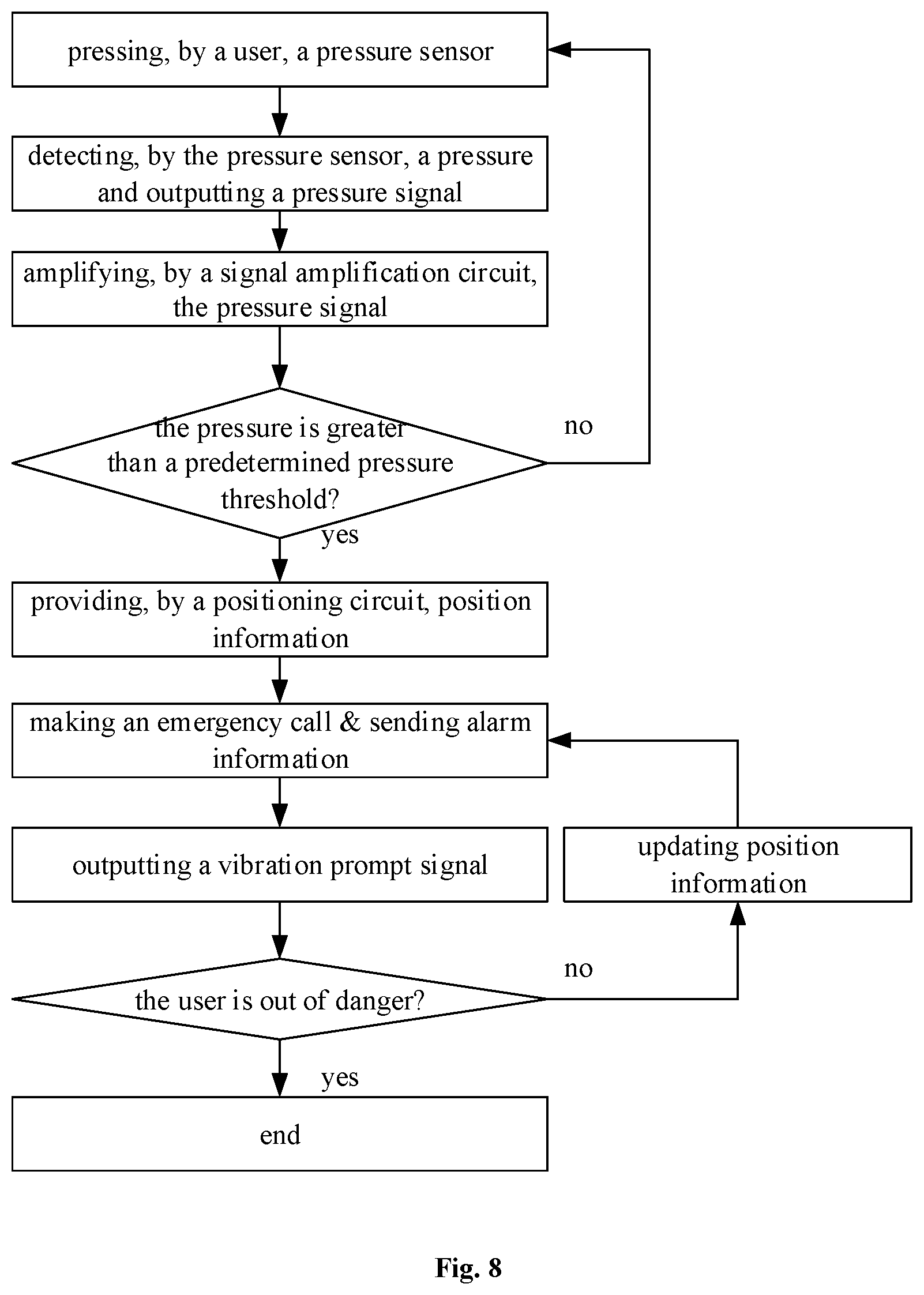
[0029] FIG. 8 is another flow chart of the controlling method according to one embodiment of the present disclosure.
DETAILED DESCRIPTION
[0030] In order to make the objects, the technical solutions and the advantages of the present disclosure more apparent, the present disclosure will be described hereinafter in a clear and complete manner in conjunction with the drawings and embodiments. Obviously, the following embodiments merely relate to a part of, rather than all of, the embodiments of the present disclosure, and based on these embodiments, a person skilled in the art may, without any creative effort, obtain the other embodiments, which also fall within the scope of the present disclosure.
[0031] The present disclosure provides in some embodiments a terminal device. As shown in FIG. 1, in a possible embodiment of the present disclosure, the terminal device may include a terminal body and a pressure sensor 110 arranged at a lateral side of the terminal body.
[0032] The terminal device may further include an execution circuit 620 connected to the pressure sensor 110 and configured to execute a predetermined operation when a pressure detected by the pressure sensor 110 is not smaller than a predetermined pressure threshold.
[0033] The terminal device may include, but not limited to, a mobile phone, a flat-panel computer, an eBook reader, an MP3 player, an MP4 player, a digital camera, a laptop computer, a wearable device or a remote controller.
[0034] The predetermined operation executed by the execution circuit 620 may be an operation set by the terminal device itself, or an operation set in accordance with an input made by a user. During the implementation, upon the detection of the pressure, the pressure sensor 110 may generate a corresponding pressure signal and transmit it to the execution circuit 620. Upon the receipt of the pressure signal from the pressure sensor 110, the execution circuit 620 may perform the predetermined operation.
[0035] The execution circuit 620 may include a microprocessor, a control chip or a control circuit.
[0036] When the execution circuit 620 includes the microprocessor, an output end of the pressure sensor 110 may be connected to the microprocessor. Upon the detection of the pressure signal from the pressure sensor 110, the microprocessor may generate a control signal corresponding to the predetermined operation, and control the terminal device to perform a corresponding operation.
[0037] When the execution circuit 620 includes the control chip or the control circuit, the execution circuit 620 may set a triggering level for the control chip or the control circuit in accordance with the predetermined pressure threshold.
[0038] For example, the control chip or the control circuit is configured to trigger and execute the predetermined operation when the triggering level is met. In addition, the triggering level may be a high level, and the control chip or control circuit may not be triggered at a low level. When the pressure detected by the pressure sensor 110 is smaller than the predetermined pressure threshold, a level of the pressure signal may not reach the triggering level. When the pressure detected by the pressure sensor 110 is not smaller than the predetermined pressure threshold, the level of the pressure signal may be greater than or equal to the triggering level, so the control chip or the control circuit may be triggered so as to execute the predetermined operation when the pressure detected by the pressure sensor 110 is greater than the predetermined pressure threshold.
[0039] When the terminal device is a mobile phone, the execution circuit is configured to perform the predetermined operation which includes, but not limited to, unlocking a screen of the mobile phone, activating a certain application, making a phone call, and sending a short message. Taking a phone call as an example, when the mobile phone is a screen-off or screen-on state and the pressure detected by the pressure sensor 110 is greater than the predetermined pressure threshold, the mobile phone may directly make a phone call.
[0040] For different terminal devices, corresponding predetermined operations may be set, and the predetermined operation may be directly executed through controlling the pressure sensor 110, so as to simplify a control procedure.
[0041] The predetermined pressure threshold may be set according to the practical need. Usually, the predetermined pressure threshold may be set in accordance with a pressure generated by a conventional operation. For example, for the terminal device such as the mobile phone or the flat-panel computer, the predetermined pressure threshold may be set in accordance with a pressure generated when the terminal device is held by a user's hand. Obviously, a range of the predetermined pressure threshold may be adjusted in some special cases.
[0042] According to the terminal device in the embodiments of the present disclosure, through the pressure sensor 110 and the execution circuit 620, when the pressure has been detected by the pressure sensor 110 and the corresponding predetermined operation has been configured, the execution circuit 620 may execute the predetermined operation. As a result, it is able to simplify the control procedure, and facilitate the use thereof.
[0043] In another possible embodiment of the present disclosure, as shown in FIG. 2, there may exist at least two pressure sensors 110, and each pressure sensor 110 may consist of one or more pressure sensing units. For example, each pressure sensing unit may be a strain gauge, or a piezoelectric ceramic sheet. Each pressure sensor 110 may merely include one pressure sensing unit. In order to improve the pressure detection accuracy, a plurality of pressure sensing units may be integrated into one pressure sensor 110.
[0044] At least one pressure sensor 110 may be arranged at each of two opposite lateral sides of the terminal body. It should be appreciated that, the terminal body may have two opposite lateral sides, e.g., a left lateral signal and a right lateral side. One or more pressure sensors 110 may be arranged at each of the lateral sides.
[0045] When the terminal device is the mobile phone, the mobile phone may include a display panel 121, and some buttons, e.g., a volume button 123 and an on/off button 124, may be arranged on a middle frame 122 of the mobile phone.
[0046] The lateral sides of the mobile phone may refer to the middle frame 122 in FIG. 2, and at least one pressure sensor 110 may be arranged at each of the two opposite lateral sides of the mobile phone. In this regard, during the implementation, the pressure signal may be detected through any of the pressure sensors 110, so as to facilitate the operation.
[0047] In a possible embodiment of the present disclosure, when at least two pressure sensors 110 are arranged on the terminal body of the terminal device and at least one pressure sensor 110 is arranged at each of the two opposite lateral sides of the terminal body, the execution circuit 620 is further configured to execute the predetermined operation when the pressure detected by at least one pressure sensor 110 at each of the two opposite lateral sides of the terminal body is not smaller than the predetermined pressure threshold.
[0048] It should be appreciated that, at this time, the predetermined operation may be executed merely when the pressure has been detected by the pressure sensor 110 at each of the two opposite lateral sides of the terminal body.
[0049] It should be appreciated that, in use, when the terminal device, e.g., the mobile phone, is placed into a bag, the pressure sensor 110 may be touched accidently. However, as compared with a situation where the pressure sensor 110 at one lateral side is touched accidently, the probability of touching the pressure sensors 110 at both the two lateral sides at a pressure greater than the predetermined pressure threshold is very small. Hence, the pressure detected by the pressure sensor 110 at a single lateral side may probably be generated due to the accident touch, but the pressures detected by the pressure sensors at both of the two lateral sides may probably be generated due to the user's operation.
[0050] Through executing the predetermined operation merely when the pressure detected by at least one pressure sensor 110 at each of the two opposite lateral sides of terminal body is not smaller than the predetermined pressure threshold, it is able to prevent the execution of the predetermined operation due to the accident touch, thereby to improve the accuracy during the use of the terminal device.
[0051] In a possible embodiment of the present disclosure, the terminal device may further include a communication circuit 640 connected to the execution circuit 620. The execution circuit 620 is further configured to control the communication circuit 640 to send an alarm signal. To be specific, the communication circuit 640 is configured to make an emergency call and/or send alarm information.
[0052] In the embodiments of the present disclosure, the terminal device is configured to rapidly send the alarm signal in accordance with the pressure detected by the pressure sensor 110. When the user needs to make an emergency call rapidly in the case of danger, it is merely necessary for the user to press the pressure sensor 110. The operation is relatively simple, so it is able to prevent the user from operating the terminal device not calmly in the case of a danger due to being nervous, or prevent the user's behavior of making the emergency call from being exposed.
[0053] To be specific, the user may make a local emergency call normally and then communicate with a receptionist. Also, the user may make the emergency call and then play a previously-recorded audio file including information about the user as well as information about a current position. The information about the current position may be acquired through calling positioning software or a positioning circuit 630, and then sent to the receptionist through voice. The positioning software may be known in the art, i.e., map software. The positioning circuit 630 may include a Beidou positioning system, or a Global Positioning System (GPS).
[0054] The alarm information may be sent to a warning platform via short messages or communication software, and the alarm information may also include the information about the user and the information about the current position. The information about the current position may be provided by the positioning software or the positioning circuit 630. Specifically, the desired information may be provided in the form of words or pictures.
[0055] During the implementation, the user may merely make the emergency call, or merely send the alarm information, or make the emergency call and send the alarm information simultaneously, so as to send the alarm signal rapidly.
[0056] In a possible embodiment of the present disclosure, the terminal device may further include a feedback circuit 650 connected to the communication circuit 640 and the execution circuit 620, and configured to control the communication circuit 640 to send the alarm signal continuously when the alarm signal has been sent but no input for interrupting the alarm signal has been detected.
[0057] After the user has sent the alarm signal in the case of danger, the user's position may change. For example, after the user has met a criminal and sent the alarm signal through the terminal device, the user may flee the scene. Hence, the information about the user's position carried in the alarm signal may not the information about a current position of the user. Hence, when the user does not interrupt the alarm signal, the feedback circuit 650 may control the communication circuit 640, directly or via the execution circuit 620, to send the alarm signal continuously.
[0058] When the alarm signal is sent continuously, the information about the user's position may be updated, so as to provide up-to-date information about the user, e.g., up-to-date position information. The alarm signal may be interrupted after the user has been out of danger, e.g., after the police has arrived and the user's safety is ensured.
[0059] Hence, the alarm signal may be sent continuously merely after the alarm signal has been sent manually for the first time, so as to continuously update the information about the user without any additional operation.
[0060] In a possible embodiment of the present disclosure, the terminal device may further include a vibration circuit configured to send a vibration prompt signal after the communication circuit 640 has sent the alarm signal, e.g., has made the emergency call and/or sent the alarm information.
[0061] In the embodiments of the present disclosure, the vibration circuit may be provided so as to prompt the user that the alarm signal has been sent successfully. After the alarm information has been sent successfully, the vibration prompt signal may be sent, so as to prompt the user that the alarm signal has been sent successfully. The vibration circuit may be provided in the form of a new vibration motor or a vibration motor existing in the terminal device. As compared with voice or ringtone, it is able to ensure the user's security in some emergency cases through the vibration prompt signal.
[0062] In addition, when the alarm signal has been sent indeed due to accident touch, the user may also be prompted that the accident touch occurs through the vibration prompt signal, so the user may interrupt the alarm signal in time.
[0063] In a possible embodiment of the present disclosure, as shown in FIG. 3, the pressure sensor 110 may include four strain gauges, i.e., a first strain gauge 111, a second strain gauge 112, a third strain gauge 113 and a fourth strain gauge 114, which may be connected in an end-to-end manner to form a bridge.
[0064] After the formation of the bridge, every two opposite strain gauges may be parallel to each other, and every two adjacent strain gauges may be angled relative to each other at an angle greater than 0.degree. and smaller than 180.degree.. Usually, for ease of calculation, the two adjacent strain gauges may be perpendicular to each other.
[0065] A connection end may be formed between every two adjacent strain gauges, so the bridge may include four connection ends, i.e., a first connection end 115, a second connection end 116, a third connection end 117 and a fourth connection end 118. The first connection end 115 and the third connection end 117 may be connected to two ends of an excitation power source respectively, and the excitation power source is configured to provide an excitation voltage E. The second connection end 116 and the fourth connection end 118 may be connected to two output ends of the pressure sensor 110 respectively, and each output end of the pressure sensor 110 is configured to output a pressure signal U. In other words, the four strain gauges may form a Wheatstone bridge.
[0066] The four strain gauges may be different from each other. However, for ease of calculation, the four strain gauges may be the same, i.e., they may have a same resistance and same strain sensitivity when a strain is 0.
[0067] The two opposite strain gauges extend in a same direction, so same deformation may occur, i.e., they may have a same resistance variation. When a pressure is applied in a specific direction, the resistance variations of the two adjacent strain gauges may have an equal size but may be opposite to each other. To be specific, when a resistance of each of the first strain gauge 111 and the third strain gauge 113 is incremented by .DELTA.R, a resistance of each of the second strain gauge 112 and the fourth strain gauge 114 may be decremented by .DELTA.R.
[0068] Hence, for the pressure sensor 110, U=E*.DELTA.R/R, where U represents an output voltage (i.e., the pressure signal) from the pressure sensor 110, E represents the excitation voltage from the excitation power source and has a constant value, .DELTA.R represents the resistance variation, and R represents an original resistance of each strain gauge and has a constant value.
[0069] The larger the pressure applied to the pressure sensor 110 is, the larger the strain detected by each strain gauge is, and the larger the resistance variation .DELTA.R of each strain gauge is. Because the excitation voltage E and the original resistance R of each strain gauge each have a constant value, a larger output voltage U may be outputted by the pressure sensor 110 when the resistance variation .DELTA.R is larger.
[0070] Based on the above calculation and analysis, the larger the pressure is, the larger the output voltage UE is. Hence, whether the pressure detected by the pressure sensor 110 is greater than the predetermined pressure threshold may be determined through determining whether the output voltage U from the pressure sensor is greater than a predetermined voltage threshold. When the output voltage U from the pressure sensor is greater than the predetermined voltage threshold, it means that the pressure detected by the pressure sensor is greater than the predetermined pressure threshold, and when U is smaller than the predetermined voltage threshold, it means that the pressure detected by the pressure sensor is smaller than the predetermined pressure threshold.
[0071] In a possible embodiment of the present disclosure, the pressure sensor 110 may include a substrate and four strain patterns on the substrate, and each strain pattern may form a strain gauge.
[0072] During the implementation, an elastic substrate may be provided at first, and then the strain patterns may be formed on the elastic substrate through sputtering or evaporation. Each strain pattern may be made of a semiconductor material or a metal material. In this regard, each strain pattern may form a strain gauge. Then, the stain gauges may be connected to each other via a conductive structure.
[0073] When the substrate is deformed due to a pressure applied thereto, each strain gauge may be deformed too, and the resistance of the strain gauge may change too. In this regard, it is able to detect the pressure applied to the substrate.
[0074] In a possible embodiment of the present disclosure, the terminal device may further include a signal amplification circuit 610, an input end of which is connected to the output end of the pressure sensor 110, and an output end of which is connected to an input end of the execution circuit 620.
[0075] The signal amplification circuit 610 is configured to amplify the output voltage from the pressure sensor 110. Usually, the output voltage from the pressure sensor 110 is at a millivolt (mV) level, so a relatively large measurement error may probably occur. Hence, the output voltage from the pressure sensor 110 may be amplified by the signal amplification circuit 610, and then the amplified output voltage may be compared with the predetermined voltage threshold, so as to determine whether the pressure detected by the pressure sensor is greater than the predetermined pressure threshold, thereby to improve the measurement accuracy.
[0076] In a possible embodiment of the present disclosure, as shown in FIG. 4, the signal amplification circuit 610 may include a first operational amplifier 141, a second operational amplifier 142, a third operational amplifier 143, a first resistor 131, a second resistor 132, a third resistor 133, a fourth resistor 134, a fifth resistor 135, a sixth resistor 136 and a variable resistor 137.
[0077] An input end of the signal amplification circuit 610 may be connected to an in-phase input end of the first operational amplifier 141 and an in-phase input end of the second operational amplifier 142.
[0078] An output end of the first operational amplifier 141 may be connected to a first end of the first resistor 131 and a first end of the second resistor 132, and a reversed-phase input end of the first operational amplifier 141 may be connected to a second end of the second resistor 132.
[0079] An output end of the second operational amplifier 142 may be connected to a first end of the third resistor 133 and a first end of the fourth resistor 134, and a reversed-phase input end of the second operational amplifier 142 may be connected to a second end of the fourth resistor 134.
[0080] A first end of the variable resistor 137 may be connected to the second end of the second resistor 132, and a second end of the variable resistor 137 may be connected to the second end of the fourth resistor 134.
[0081] A second end of the first resistor 131 may form a first output end 151 of the signal amplification circuit 610, the second end of the first resistor 131 may be further connected to a first end of the fifth resistor 135, and a second end of the fifth resistor 135 may be connected to a ground line.
[0082] A second end of the third resistor 133 may form a second output end 152 of the signal amplification circuit 610, and the second end of the third resistor 133 may be further connected to a first end of the sixth resistor 136.
[0083] An in-phase input end of the third operational amplifier 143 may be connected to the first output end 151 of the signal amplification circuit 610, a reversed-phase input end of the third operational amplifier 143 may be connected to the second output end 152 of the signal amplification circuit 610, and an output end of the third operational amplifier 143 may be connected to a third output end 153 of the signal amplification circuit 610.
[0084] For the signal amplification circuit 610, U1-U2=(R2+R4+Rw)Uin/Rw. When R5=R6=Rx and R1=R3=Ry, Uo=-(Rx/Ry)*(Uo1-Uo2)=-(Rx/Ry)*(R2+R3+Rw)*Uin/Rw, and when R2=R3=R, Uo=-Rx/Ry*(1+2R/Rw)*Uin, where U1 and U2 represent the output voltages from the first output end 151 and the second output end 152 respectively, R1, R2, R3, R4, R5 and R6 represent resistances of the first resistor 131, the second resistor 132, the third resistor 133, the fourth resistor 134, the fifth resistor 135 and the sixth resistor 136 respectively, Rw represents a resistance of the variable resistor 137, and Uin represents an input voltage applied to the input end, i.e., the pressure signal applied from the output end of the pressure sensor 110 to the signal amplification circuit 610.
[0085] Based on the above equations, when the Rx, Ry and R each have a constant value and the output voltage Uin from the pressure sensor 110 has a value based on the pressure, Uo may be a function related to Rw, so Uo may be adjusted through adjusting the resistance of Rw. In other words, an amplification factor may be adjusted through adjusting Rw. When Rw has been adjusted to a specific value, Uo may have a value merely related to Uin.
[0086] For the signal amplification circuit 610, the first operational amplifier 141 and the second operational amplifier 142 may form a differential amplifier, so as to acquire a relatively high input impedance, thereby to suppress common-mode interference. The output voltage may be further amplified in a reversed-phase manner through the third operational amplifier 143, so it is able to amplify the output voltage to be at a volt level.
[0087] Obviously, the structure of the signal amplification circuit 610 will not be particularly defined herein. Also, a known signal amplification circuit in the art or a signal amplification circuit that may occur in future may also be adopted to amplify the signal collected by the pressure sensor 110.
[0088] In a possible embodiment of the present disclosure, the terminal body may include a housing. As shown in FIG. 5, an opening 160 penetrating through the housing may be provided at a lateral side of the housing, and the pressure sensor 110 may be received in the opening 160.
[0089] In the embodiments of the present disclosure, through receiving the pressure sensor 110 in the opening 160 at the lateral side of the housing, it is able to conveniently determine the position of the pressure sensor 110, and facilitate the operation when the pressure sensor 110 is touched by the user. For example, it is merely necessary for the user to press the pressure sensor 110 in the case of danger without exposing the mobile phone to a criminal, thereby to send the alarm signal in a hidden manner.
[0090] As shown in FIG. 6, generally, a working procedure of the terminal device may include generating, by the pressure sensor 110, the pressure signal (i.e., an output signal) upon the detection of the pressure, transmitting, by the pressure sensor 110, the pressure signal to the signal amplification circuit 610, amplifying, by the signal amplification circuit 610, the pressure signal, transmitting, by the signal amplification circuit 610, the amplified pressure signal to the execution circuit 620, and then executing, by the execution circuit 620, the predetermined operation.
[0091] When the predetermined operation includes sending the alarm information, the execution circuit 620 may control the communication circuit 640 to send the alarm information.
[0092] When the sending the alarm information includes making the emergency call and sending an alarm short message, the communication circuit 640 may include a phone-call alarm sub-circuit 641 and a short-message alarm sub-circuit 642. The execution circuit 620 is further configured to control the phone-call alarm sub-circuit 641 and the short-message alarm sub-circuit 642 to send the alarm information via a phone call and a short message respectively.
[0093] The terminal device may further include a positioning circuit 630. When sending the alarm information, position information acquired by the positioning circuit 630 may also be sent, so as to determine a position of the user.
[0094] In addition, the terminal device may further include a feedback circuit 650 connected to the communication circuit 640. When the user has not been out of danger and the alarm signal has not been interrupted, the feedback circuit 650 is configured to send the alarm signal continuously through the communication circuit 640. When sending the alarm signal continuously, the position information about the user may be updated, until the user has been out of danger and the alarm signal has been interrupted.
[0095] The present disclosure further provides in some embodiments a method of controlling the above-mentioned terminal device.
[0096] As shown in FIG. 7, the method may include Step 701 of executing a predetermined operation when a pressure detected by the pressure sensor is not smaller than a predetermined pressure threshold.
[0097] According to the method in the embodiments of the present disclosure, through the pressure sensor and the execution circuit, when the pressure has been detected by the pressure sensor and the corresponding predetermined operation has been configured, the execution circuit may execute the predetermined operation. As a result, it is able to simplify the control procedure, and facilitate the use thereof.
[0098] In a possible embodiment of the present disclosure, when there are at least two pressure sensors and at least one pressure sensor is arranged at each of two opposite lateral sides of the terminal body, Step 701 may include, when the pressure detected by the at least one pressure sensor at each of the two opposite lateral sides of the terminal body is not smaller than the predetermined pressure threshold, executing the predetermined operation.
[0099] In the embodiments of the present disclosure, through executing the predetermined operation merely when the pressure detected by at least one pressure sensor at each of the two opposite lateral sides of terminal body is not smaller than the predetermined pressure threshold, it is able to prevent the execution of the predetermined operation due to the accident touch, thereby to improve the accuracy during the use of the terminal device.
[0100] In a possible embodiment of the present disclosure, when the terminal device further includes a communication circuit connected to the execution circuit, the executing the predetermined operation may include controlling, by the execution circuit, the communication circuit to send an alarm signal. The alarm signal is making an emergency call and/or sending alarm information.
[0101] In the embodiments of the present disclosure, it is able to send the alarm signal rapidly and conveniently in a relatively secrete manner. As a result, it is able to prevent the user from operating the terminal device not calmly in the case of a danger due to being nervous, or prevent the user's behavior of making the emergency call from being exposed.
[0102] To be specific, the user may make a local emergency call normally and then communicate with a receptionist. Also, the user may play a previously-recorded audio file including information about the user as well as information about a current position. The information about the current position may be acquired through calling positioning software or a positioning circuit, and then sent to the receptionist through voice. The positioning software may be known in the art, i.e., map software. The positioning circuit may include a Beidou positioning system, or a GPS.
[0103] The alarm information may be sent to a warning platform via short messages or communication software, and the alarm information may also include the information about the user and the information about the current position. The information about the current position may be provided by the positioning software or the positioning circuit. Specifically, the desired information may be provided in the form of words or pictures.
[0104] During the implementation, the user may merely make the emergency call, or merely send the alarm information, or make the emergency call and send the alarm information simultaneously, so as to send the alarm signal rapidly.
[0105] In a possible embodiment of the present disclosure, subsequent to controlling, by the execution circuit, the communication circuit to send the alarm signal, the method may further include sending a vibration prompt signal.
[0106] In the embodiments of the present disclosure, the vibration circuit may be provided so as to prompt the user that the alarm signal has been sent successfully. After the alarm information has been sent successfully, the vibration prompt signal may be sent, so as to prompt the user that the alarm signal has been sent successfully. The vibration circuit may be provided in the form of an additional vibration motor or a vibration motor existing in the terminal device. As compared with voice or ringtone, it is able to ensure the user's security in some emergency cases through the vibration prompt signal.
[0107] In addition, when the alarm signal has been sent indeed due to accident touch, the user may also be prompted that the accident touch occurs through the vibration prompt signal, so the user may interrupt the alarm signal in time.
[0108] In a possible embodiment of the present disclosure, when the terminal device further includes a feedback circuit connected to the communication circuit and the execution circuit, subsequent to the controlling, by the execution circuit, the communication circuit to send the alarm signal, the method may further include controlling, by the feedback circuit, the communication circuit to continue to send the alarm signal when the alarm signal has been sent but no input for interrupting the alarm signal has been detected.
[0109] When the input for interrupting the alarm signal has been detected, e.g., when the user has already been out of danger or the alarm signal is sent due to the accidental touch, the alarm signal may be interrupted, so as to prevent the waste of social resources. When no input for interrupting the alarm signal has been detected, the alarm signal may be sent continuously, so as to provide up-to-date state information in the alarm information in time, e.g., to update the position information about the user, thereby to ensure the communication connection and facilitate the understanding of the up-to-date state information about the user.
[0110] As shown in FIG. 8, when the executing the predetermined operation includes sending the alarm signal, a procedure of the method may be generally described as follows. When the user needs to send the alarm signal in the case of danger, the user may press the pressure sensor. Upon the detection of the pressure, the pressure sensor may output the pressure signal to the signal amplification circuit, and then the pressure signal may be amplified by the signal amplification circuit.
[0111] After the pressure signal has been amplified, the amplified pressure signal may be compared with the predetermined voltage threshold so as to determine whether the pressure detected by the pressure sensor is greater than the predetermined pressure threshold. When the pressure is greater than the predetermined pressure threshold, the position information about the user may be provided by the positioning circuit, and the alarm signal may be sent. The sending the alarm signal may include making an emergency call or sending the alarm information. After the alarm signal has been sent successfully, the vibration prompt signal may be outputted so as to prompt the user that the alarm signal has been sent successfully.
[0112] Before the user is out of danger, the position information may be updated and the alarm signal may be sent continuously. After the user is out of danger, the alarm signal may be interrupted.
[0113] In a possible embodiment of the present disclosure, the predetermined pressure threshold may at least include a first pressure threshold and a second pressure threshold greater than the first pressure threshold, and the predetermined operation may at least include a first predetermined operation and a second predetermined operation different from the first predetermined operation.
[0114] Step 701 may include: when the pressure detected by the pressure sensor is not smaller than the first pressure threshold and not greater than the second pressure threshold, executing the first predetermined operation; and when the pressure detected by the pressure sensor is not smaller than the second pressure threshold, executing the second predetermined operation.
[0115] In the embodiments of the present disclosure, different predetermined operations may be triggered through different pressures. The following description will be given when the first predetermined operation includes photographing, the second predetermined operation includes starting the browser, the first pressure threshold is 200N, and the second pressure threshold is 400N.
[0116] During the implementation, when the pressure detected by the pressure sensor is not smaller than 200N and not greater than 400N, a photographing operation may be executed, and when the pressure detected by the pressure sensor is not smaller than 400N, the bowser may be started. In this regard, it is able to trigger different operations through different pressures.
[0117] Obviously, the pressure thresholds will not be particularly defined herein. During the implementation, different pressures may be tested in advance, and then the pressure thresholds may be set correspondingly. The pressure threshold may be preset in accordance with an input. The first predetermined operation and the second predetermined operation may also include sending the alarm signal, photographing, or opening or closing an application.
[0118] In a possible embodiment of the present disclosure, the number of the pressure thresholds will not be particularly defined herein. For example, three pressure thresholds may be set, and different predetermined operations may correspond to different pressure ranges.
[0119] Through providing a plurality of pressure thresholds and providing a plurality of predetermined operations, it is able to call different functions of the terminal device conveniently, thereby to facilitate the operation.
[0120] The present disclosure provides in some embodiments a terminal device, including a processor, a memory, and a computer program stored in the memory and executed by the processor. The processor is configured to execute the computer program so as to implement the above-mentioned method.
[0121] The present disclosure further provides in some embodiments a computer-readable storage medium storing therein a computer program. The computer program is executed by a processor so as to implement the above-mentioned method.
[0122] The implementation of the terminal device and the computer-readable storage medium may refer to that of the method mentioned hereinabove with a same technical effect, which will not be particularly defined herein.
[0123] The above embodiments are for illustrative purposes only, but the present disclosure is not limited thereto. Obviously, a person skilled in the art may make further modifications and improvements without departing from the spirit of the present disclosure, and these modifications and improvements shall also fall within the scope of the present disclosure.
* * * * *
D00000
D00001
D00002
D00003
D00004
XML
uspto.report is an independent third-party trademark research tool that is not affiliated, endorsed, or sponsored by the United States Patent and Trademark Office (USPTO) or any other governmental organization. The information provided by uspto.report is based on publicly available data at the time of writing and is intended for informational purposes only.
While we strive to provide accurate and up-to-date information, we do not guarantee the accuracy, completeness, reliability, or suitability of the information displayed on this site. The use of this site is at your own risk. Any reliance you place on such information is therefore strictly at your own risk.
All official trademark data, including owner information, should be verified by visiting the official USPTO website at www.uspto.gov. This site is not intended to replace professional legal advice and should not be used as a substitute for consulting with a legal professional who is knowledgeable about trademark law.