Heat Exchanger Tube And Corresponding Heat Exchanger
Marchadier; Xavier ; et al.
U.S. patent application number 16/610307 was filed with the patent office on 2020-07-30 for heat exchanger tube and corresponding heat exchanger. This patent application is currently assigned to Valeo Systemes Thermiques. The applicant listed for this patent is Valeo Systemes Thermiques. Invention is credited to Xavier Marchadier, Christian Riondet.
| Application Number | 20200240714 16/610307 |
| Document ID | 20200240714 / US20200240714 |
| Family ID | 1000004786192 |
| Filed Date | 2020-07-30 |
| Patent Application | download [pdf] |
| United States Patent Application | 20200240714 |
| Kind Code | A1 |
| Marchadier; Xavier ; et al. | July 30, 2020 |
HEAT EXCHANGER TUBE AND CORRESPONDING HEAT EXCHANGER
Abstract
The tube (5) of a heat exchanger (1) is produced from a strip of material (11), the strip of material (11) having two end parts joined such as to form the tube (5). The strip of material (11) forming the tube (5) is folded on itself such as to define at least one fold (13) formed by two strip portions (13a, 13b) with continuity of material. At least one strip portion (13a, 13b) of the fold (13) is a strip portion (13a, 13b) for protecting the tube (5) in the event of an impact from an element outside the tube (5) and is formed in an intermediate part (11 b) of the strip of material (11).
| Inventors: | Marchadier; Xavier; (Le Mesnil Saint-Denis, FR) ; Riondet; Christian; (Reims, FR) | ||||||||||
| Applicant: |
|
||||||||||
|---|---|---|---|---|---|---|---|---|---|---|---|
| Assignee: | Valeo Systemes Thermiques Le Mesnil-Saint-Denis Cedex FR |
||||||||||
| Family ID: | 1000004786192 | ||||||||||
| Appl. No.: | 16/610307 | ||||||||||
| Filed: | May 2, 2018 | ||||||||||
| PCT Filed: | May 2, 2018 | ||||||||||
| PCT NO: | PCT/FR2018/051093 | ||||||||||
| 371 Date: | January 9, 2020 |
| Current U.S. Class: | 1/1 |
| Current CPC Class: | F28F 1/022 20130101; F28F 2225/04 20130101; F28D 1/0391 20130101 |
| International Class: | F28D 1/03 20060101 F28D001/03; F28F 1/02 20060101 F28F001/02 |
Foreign Application Data
| Date | Code | Application Number |
|---|---|---|
| May 2, 2017 | FR | 1753851 |
Claims
1. A tube for a heat exchanger made from a strip of material, the strip of material having two end parts joined such as to form the tube, the strip of material forming the tube is folded on itself such as to define at least one fold formed by two strip portions with continuity of material such that at least one strip portion of the fold: is a strip portion for protecting the tube in the event of an impact from an element outside the tube, and is formed in an intermediate part of the strip of material.
2. The tube as claimed in claim 1, wherein the intermediate part lacks a join zone between the two end parts to close the tube in a sealed manner.
3. The tube as claimed in claim 1, wherein said at least one fold is formed along at least one lateral side of the tube.
4. The tube as claimed in claim 1, wherein the strip of material is folded such as to form a protuberance extending from the tube toward the exterior of the tube.
5. The tube as claimed in claim 4, wherein the protuberance has a thickness at least equal to twice the material thickness of the strip of material.
6. The tube as claimed claim 4, wherein the protuberance forms, with the general plane of extension of the tube, a non-zero angle of the order of 30.degree..
7. The tube as claimed in claim 4, in which the protuberance extends over a width equal to at least twice and to at most ten times the material thickness of the strip of material.
8. The tube as claimed in claim 1, wherein the strip of material is folded in the direction of the height of the tube, such as to form an excess thickness of material.
9. The tube as claimed in claim 8, wherein the height of the strip portions of said at least one fold is of the order of the height of the tube.
10. A heat exchanger for a motor vehicle, comprising: a bundle of tubes, each tube of the bundle of tubes being made from a strip of material, the strip of material having two end parts joined such as to form each tube, wherein the strip of material forming each tube is folded on itself such as to define at least one fold formed by two strip portions with continuity of material such that at least one strip portion of the fold: is a strip portion for protecting each tube in the event of an impact from an element outside each tube, and is formed in an intermediate part of the strip of material.
11. A tube for a heat exchanger made from a strip of material, the strip of material comprising two end parts joined such as to form the tube, the tube comprising two lateral ends and an intermediate part; wherein the strip of material forming the tube is folded on itself such as to define at least one fold formed by two strip portions with continuity of material such that at least one strip portion of the fold: is a strip portion for protecting the tube in the event of an impact from an element outside the tube, and is formed in the intermediate part of the strip of material, wherein the intermediate part is the portion of the tube that does not include the lateral ends of the tube and is a longitudinal extension corresponding to the longitudinal extension of the tube.
Description
[0001] The invention relates to a heat exchanger tube, notably for motor vehicles. The invention also relates to a heat exchanger comprising a bundle of such tubes.
[0002] The invention pertains to the field of heat exchangers, notably for motor vehicles.
[0003] The present invention relates in particular to heat exchangers designed to be placed at the front end of a motor vehicle. A front end, also called a front end assembly, is a structural element that is able to incorporate a variety of equipment of the vehicle, such as headlamps, flashers, audible warning device, heat exchangers, engine fans or cooling module.
[0004] The heat exchanger is, for example, used to cool the engine or, again, to air-condition the car interior.
[0005] Generally, heat exchangers conventionally comprise a bundle of tubes and collector boxes into which the ends of the tubes of the bundle open out such as to allow the circulation of a fluid, notably a cooling fluid, in the tubes of the bundle.
[0006] The tubes of such exchangers may be produced, for example, by extrusion. This type of manufacture gives rise to a significant cost, however, notably owing to the need for specific dies for each type of tube.
[0007] In a variant, tubes are produced from a strip of material, for example, by folding the strip of material.
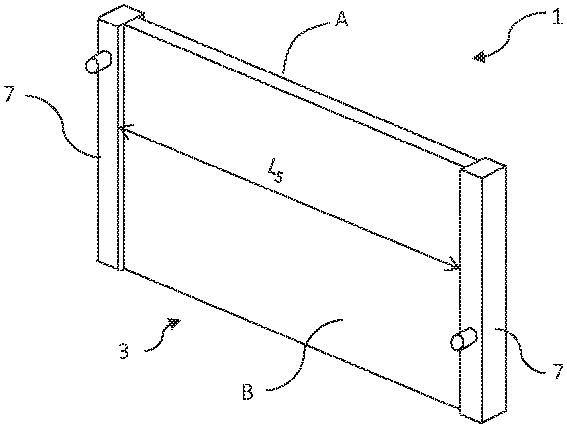
[0008] However, the tubes of heat exchangers may be subject to numerous stresses, such as a high-speed impact with an object (for example, a piece of gravel) originating from the exterior environment. The tubes of heat exchangers are thus subject to exterior stresses. The fluid must not escape from the tubes of heat exchangers as this is likely to compromise the way in which these heat exchangers function, so it is necessary to preserve the exterior/fluid leaktightness of the tubes.
[0009] With a view to protecting these heat exchangers, a grille, generally one made from plastics, may be incorporated at the front end in order to stop pieces of gravel. Nevertheless, the integration of such a grille at the front end engenders a certain cost.
[0010] It has proven to be useful to guarantee that the material used for the tube is sufficiently strong in order to prevent any risk of fluid escaping from the heat exchanger, for example in the event of an impact with a piece of gravel on the road.
[0011] A known solution is to enable the tube to withstand such an impact by locally increasing the thickness of the wall of the tube in the case of an extruded tube. However, such tubes are expensive to manufacture. Moreover, it has been observed that such tubes are less corrosion-resistant than tubes made from a strip of material, notably by folding.
[0012] In a first known tube produced from a strip of material, the end parts of the tube are folded and secured together by brazing, on a side or at the tube nose. Such folds that are brazed at the end parts require a complex manufacturing process.
[0013] Furthermore, such tubes may not be sufficiently able to withstand impact from pieces of gravel.
[0014] Thus, an object of the invention is to propose a solution for a tube produced from a strip of material, conferring, on the tube, in a simple manner, improved resistance to exterior stresses while still resolving the above-mentioned prior-art drawbacks at least in part.
[0015] To that end, a subject of the invention is a tube for a heat exchanger made from a strip of material, the strip of material having two end parts joined such as to form the tube. According to the invention, the strip of material forming the tube is folded on itself such as to define at least one fold formed by two strip portions with continuity of material such that at least one strip portion of the fold: [0016] is a strip portion for protecting the tube in the event of an impact from an element outside the tube, and [0017] is formed in an intermediate part of the strip of material.
[0018] The two strip portions of said at least one fold may be formed in the intermediate part of the strip of material.
[0019] In other words, the intermediate part of the strip of material is by definition distinct from, i.e. does not include, the lateral ends of the strip of material.
[0020] The end parts of the strip of material each include a lateral end of the strip of material.
[0021] It is possible, for example, to define the intermediate part of the strip of material as the central part corresponding to 80% of the width of the strip of material, the end parts corresponding, for example, to the parts having a width of 10% on either side of the intermediate part.
[0022] However, this value of 80% is purely indicative. The important thing is for the intermediate part not to include the lateral ends of the strip of material.
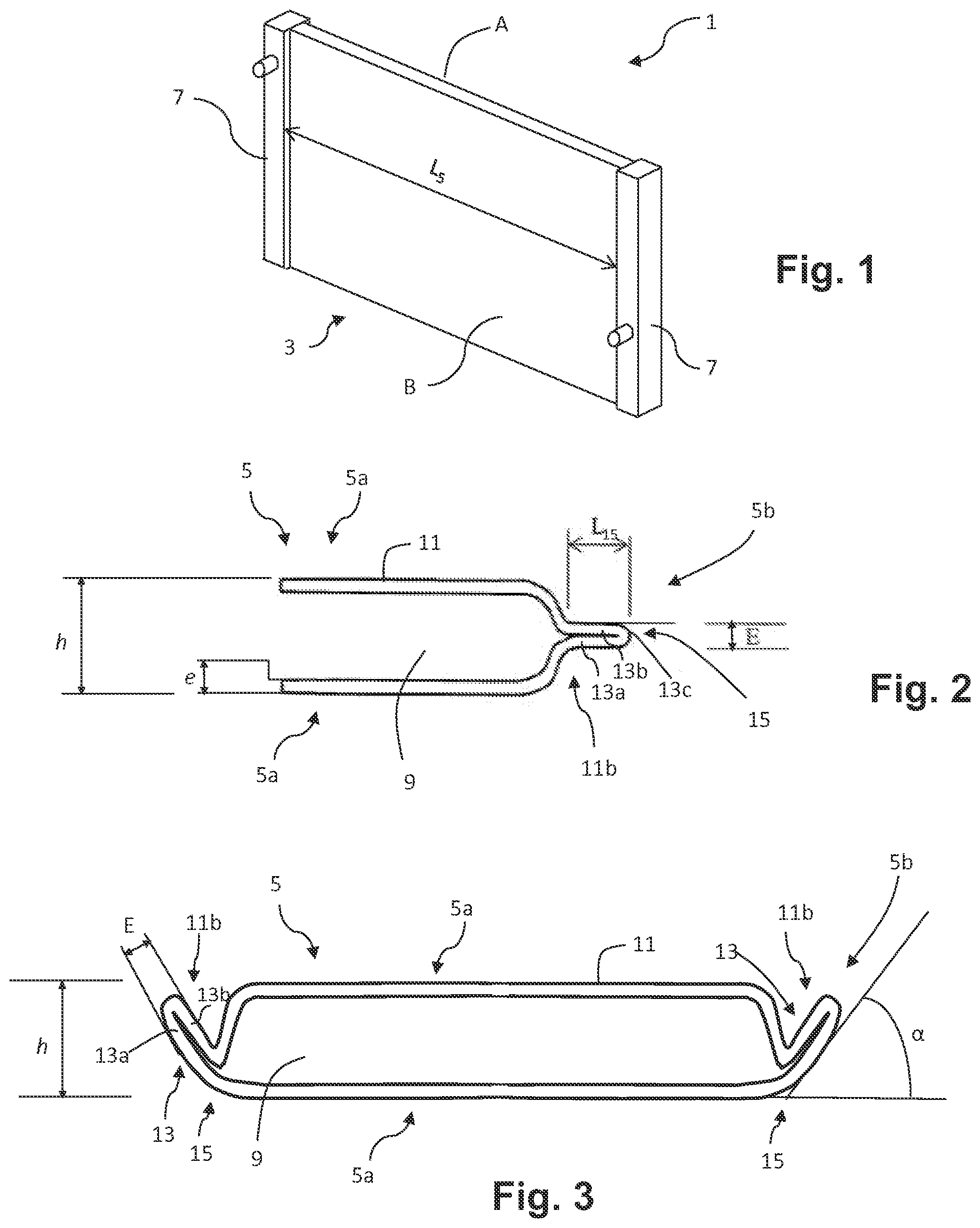
[0023] Furthermore, the intermediate part has a longitudinal extension corresponding to the longitudinal extension of the tube.
[0024] Thus, advantageously in locations where there are high levels of stress, notably stresses from outside the tube, this fold or these folds are used to create one or more zones of reinforcement of the tube that make it possible to absorb energy in the event of an impact from an element originating from the exterior environment, such as a piece of gravel.
[0025] The one or more folds are not produced in a zone where walls of the strip of material that need to be leaktight join or overlap, but the wall is folded on itself with continuity of material. Thus, even were the folds to deform or to unfold, the leaktightness of the tube, furthermore achieved, for example, by brazing or electrowelding, would remain guaranteed.
[0026] The invention thus offers the advantage of protection for the join between the end parts of the strip of material and thus the leaktightness of the tube.
[0027] Said tube may, furthermore, comprise one or more of the following features, taken separately or in combination.
[0028] Preferably, the intermediate part does not include a join zone between the two end parts in order to close the tube in a sealed manner. In other words, the intermediate part lacks such a join zone.
[0029] According to one aspect of the invention, said at least one fold is formed along at least one lateral side of the tube. This side is configured such as to be arranged on the front side of a heat exchanger facing an inlet for a flow of external air at the front end of a motor vehicle.
[0030] According to one example, the tube has two major sides connected by two lateral minor sides. Said at least one fold is formed on a lateral minor side.
[0031] According to another aspect of the invention, the strip portions of said at least one fold are brazed together such as to increase the mechanical strength of the tube.
[0032] The strip portions of said at least one fold may or may not lie against one another.
[0033] According to a first embodiment, the strip of material is folded such as to form a protuberance extending from the tube toward the exterior of the tube.
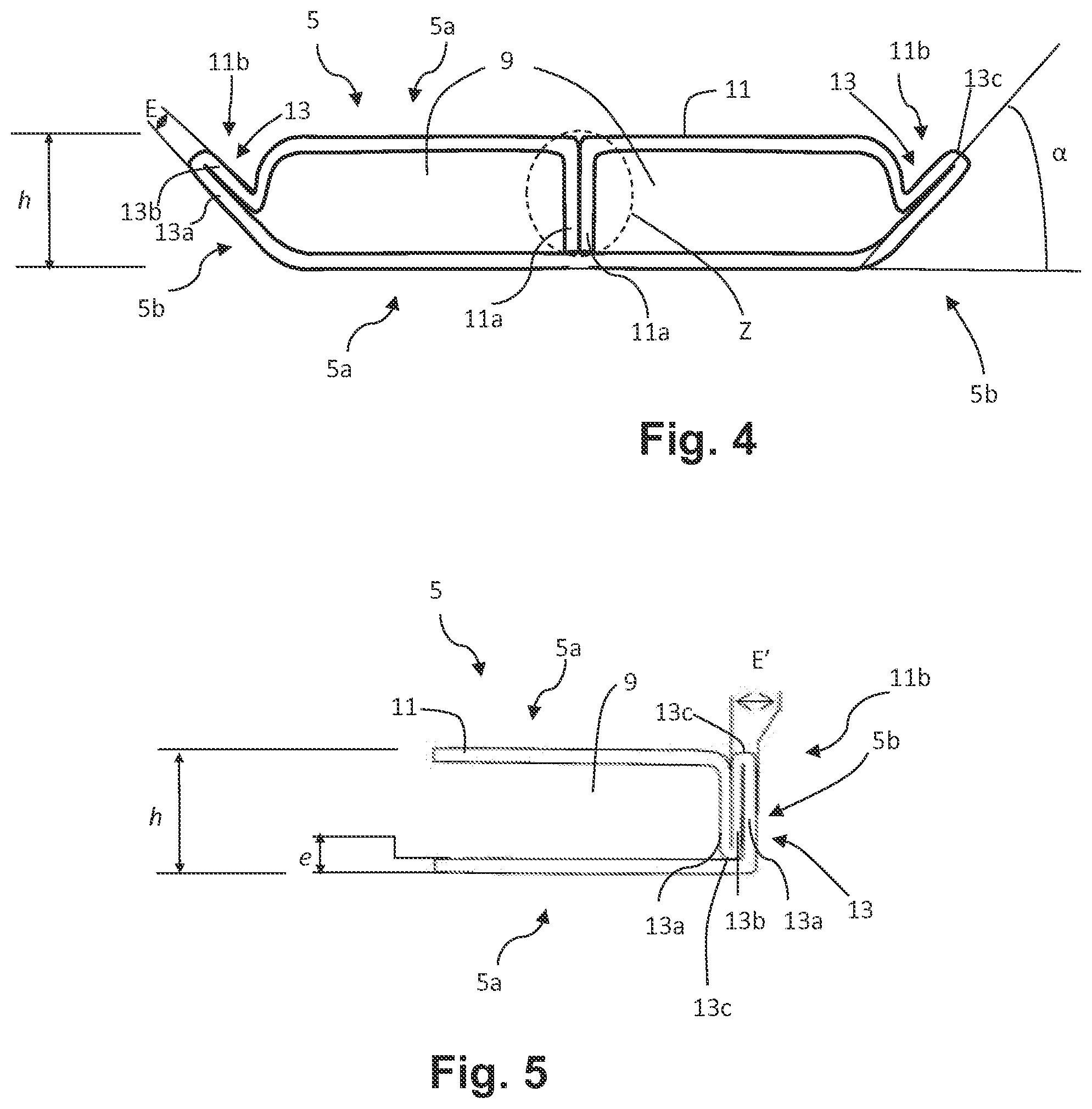
[0034] Such a protuberance is the first surface of the tube with which a piece of gravel, for example, enters into contact in the event of impact. The protuberance may fold and/or deform through the effect of the impact and thus absorb the energy of the piece of gravel.
[0035] Lastly, such a tube may be produced in a simple manner without requiring a plurality of manufacturing steps.
[0036] The protuberance may have a thickness at least equal to twice the material thickness of the strip of material.
[0037] For example, the protuberance forms, with the horizontal, a non-zero angle notably less than or of the order of 45.degree., preferably of the order of 30.degree..
[0038] The protuberance may extend over a width equal to at least twice and to at most ten times the material thickness of the strip of material.
[0039] According to a second embodiment, the strip of material is folded in the direction of the height of the tube, such as to form an excess thickness of material.
[0040] A sufficient excess thickness, advantageously provided at the nose of the tube, is obtained with a view to guaranteeing mechanical strength and thereby protecting the tube in the event of impacts originating from the exterior environment, without the risk of a leak of fluid.
[0041] The height of the strip portions of said at least one fold is, for example, of the order of the height of the tube.
[0042] According to either embodiment, the tube is a folded tube. The tube may have a cross section substantially in the form of a "B", defining two parallel fluid-circulation channels delimited by a separation.
[0043] The tube may be an electrowelded tube.
[0044] The invention further relates to a heat exchanger, notably for a motor vehicle, characterized in that it comprises a bundle of tubes as defined above.
[0045] Further features and advantages of the invention will become more clearly apparent upon reading the following description, given by way of illustrative, non-limiting example, and the appended drawings, in which:
[0046] FIG. 1 shows, in part and schematically, a heat exchanger,
[0047] FIG. 2 is a cross-sectional view showing, in part, a first example of a tube of the exchanger of FIG. 1,
[0048] FIG. 3 is a cross-sectional view of a second example of a tube of the exchanger of FIG. 1,
[0049] FIG. 4 is a cross-sectional view of a third example of a tube of the exchanger of FIG. 1, and
[0050] FIG. 5 is a cross-sectional view of a fourth example of a tube of the exchanger of FIG. 1.
[0051] In these figures, identical elements bear the same references.
[0052] The following embodiments are examples. Although the description relates to one or more embodiments this does not mean necessarily that each reference relates to the same embodiment or that the features apply to only one embodiment. Simple features from different embodiments may likewise be combined or interchanged in order to provide further embodiments.
[0053] In the description, certain elements may include an index mark such as, for example, first element or second element. In this event, this is simple indexing to differentiate and to name similar but not identical elements. This indexing does not imply that any element takes priority over any other element, and such designations may easily be interchanged without departing from the scope of the present description. This indexing does not, likewise, imply an order in terms of time.
[0054] FIG. 1 schematically shows an example of a heat exchanger 1 according to the invention. This is, in particular, a heat exchanger 1 designed to be placed at the front end of a motor vehicle.
[0055] An example that may be cited is that of radiators for cooling the engine or, again, "low-temperature" radiators, for example for auxiliary cooling circuits in the motor vehicle. It may also be, for example, a condenser of an air-conditioning circuit.
[0056] The heat exchanger 1, such as a cooling radiator, placed at the front end of the vehicle may be accessed by a first fluid, such as a flow of external air, originating from outside the vehicle. A second fluid, such as a cooling fluid, circulates inside the heat exchanger 1 such as to exchange heat with this flow of external air.
[0057] The heat exchanger 1 has a front side A, i.e. designed to be arranged on the side of the grille of the motor vehicle or, alternatively, facing an inlet for the flow of external air designed to traverse the heat exchanger 1. The heat exchanger 1 also has a rear side B, or engine side, which is opposite the front side A.
[0058] In the present description, the terms front/rear are designed to refer to the direction of progress, in a forward gear, of the motor vehicle intended to be equipped with a heat exchanger 1 as described. Similarly, the terms vertical/horizontal are designed to refer to the arrangement of the elements in FIGS. 2 to 5, which corresponds to the arrangement of the elements in the assembled state in the motor vehicle.
[0059] As illustrated in part in FIG. 1, the heat exchanger 1 conventionally comprises a bundle 3 (shown very schematically in FIG. 1) of tubes 5.
[0060] Examples of tubes 5 are in part shown in FIGS. 2 to 5. These tubes 5 are mounted between two distribution housings or collector boxes 7, also called water boxes, (referring, likewise, to FIG. 1) for the second fluid.
[0061] In the assembled state in the motor vehicle, the heat exchanger 1 may be arranged such as to allow, for example, a transverse circulation of fluid in the tubes 5 that extend transversely to the motor vehicle. There are, however, configurations in which circulation takes place vertically in vertical tubes 5.
[0062] Advantageously, the heat exchanger 1 is a "brazed" exchanger. In this case, the various component parts of the body of such a heat exchanger 1 are made from metal and may be assembled and then brazed by passing through a brazing furnace with a view to securing together all the component parts. It should be noted that other elements made from plastics, in particular, are typically attached on top after brazing, such as, for example, water boxes.
[0063] The tubes 5 (FIGS. 2 to 5) may extend longitudinally along a length L.sub.5 shown schematically in FIG. 1. The ends of these tubes 5 open out into the collector boxes 7, for example by means of collector plates (not shown), which may be arranged transversely relative to the tubes 5.
[0064] Each tube 5 delimits one or more circulation channels 9 (see FIGS. 2 to 5) for the second fluid.
[0065] The tubes 5 may be separated from one another by inserts (not shown), for example corrugated inserts, traversed by the first fluid, such as the flow of external air, for the purposes of a thermal exchange with the second fluid, such as the cooling fluid circulating in the tubes 5.
[0066] According to a variant embodiment (not shown), an internal insert, for example a corrugated insert, may be inserted in the or each circulation channel 9. This internal insert has, for example, a thickness of the order of 80 .mu.m to 140 .mu.m.
[0067] The invention relates more precisely to a tube 5 for such a heat exchanger 1, examples of which are shown schematically in FIGS. 2 to 5.
[0068] The tube 5 is produced from a strip of material 11. This is, in particular, a metallic strip 11. The metallic strip is preferably made of aluminum or aluminum alloy. The strip of material 11 is, for example, of rectangular general shape.
[0069] This strip of material 11 has a thickness e, which, below, is also called material thickness. This material thickness e is constant. By way of example, the material thickness e may be of the order of 180 .mu.m to 270 .mu.m, in particular of the order of 200 .mu.m to 270 .mu.m.
[0070] Notably, the tube 5 may be obtained from a reel of metallic foil that, after being unwound as a strip, is progressively formed to the required cross section using specific tools, for example folding or similar tools, and is then cut to the desired length, in sections corresponding to a plurality of final tubes 5.
[0071] In particular, the strip of material 11 has end parts 11a, which may be seen in the example of FIG. 4, which are joined such as to form the tube 5, notably to close the tube 5 in a leaktight manner. These end parts 11a comprise the lateral ends or lateral borders of the strip of material 11.
[0072] Leaktightness may be assured by brazing at the join of the end parts 11a. In a variant, this may be an electrowelded tube 5.
[0073] The strip of material 11 also has an intermediate part 11b. This intermediate part 11b does not include the lateral ends of the strip of material 11. The intermediate part 11b is distinct from the end parts 11a.
[0074] By way of non-limiting example, the end parts 11a of the strip of material 11 may extend on each side of the strip of material 11, each over a width of the order of 10% of the total width of the strip of material 11.
[0075] The intermediate part 11b, meanwhile, forms a central part extending, for example, over a width of the order of 80% of the total width of the strip of material 11.
[0076] Furthermore, the end parts 11a and the intermediate part 11b each have a longitudinal extension corresponding to the longitudinal extension of the tube 5.
[0077] The tube 5 may be folded or formed such as to define a single channel 9 for circulation of fluid (FIG. 3). By way of non-limiting example, the tube 5 may have a cross section of oblong general shape. The strip of material 11 then forms an envelope of this circulation channel 9.
[0078] In a variant, the tube 5 may be folded or formed such as to define at least two circulation channels 9 (FIG. 4). The tube 5 may have a cross section of "B" form.
[0079] The cross section of "B" form of the illustrated tube 5 has two juxtaposed parallel channels 9 for circulation of fluid which are separated by a separation forming a spacer. To that end, the metallic strip is folded such as to form the envelope of these juxtaposed parallel circulation channels 9. The separation is produced jointly by the folded opposite end parts 11a of the strip of material 11. In this example, the intermediate part 11b of the strip of material 11 does not include the join zone Z, which is encircled in a broken line in FIG. 4, of the two end parts 11a to form the separation.
[0080] A description has been given here of a folded tube of "B" form. Naturally, provision may be made for any other type of folding.
[0081] The end parts 11a of the strip of material 11, visible only in the example of FIG. 4, may be placed against or superposed on one another. In particular, in the example of FIG. 4, the end parts 11a may be folded up, for example substantially at a right angle, and placed against one another.
[0082] According to any of the variants shown in FIGS. 2 to 5, the tube 5 has two major sides 5a, notably with a planar surface, connected by two lateral minor sides 5b of height h, which defines the height h of the tube 5. These minor sides 5b may be rounded and are likewise called radii of the tube 5.
[0083] The height h of the tube 5 also corresponds to the overall thickness of the tube 5. This height h of a tube 5 is, for example, of the order of 1.2 mm to 3 mm.
[0084] Moreover, during the method for manufacturing the tube 5, the strip of material 11 forming the tube 5 is folded on itself such as to define, with continuity of material, at least one fold 13.
[0085] This strip of material 11 is folded on itself at least at one side of the tube 5, also called the nose of the tube 5. This is a lateral minor side 5b of the tube 5 intended to be arranged on the front side A of the heat exchanger 1. The side 5b of the tube 5 having one or more folds 13 is configured such as to extend along a transverse axis, in the direction of the width, of a motor vehicle equipped with a heat exchanger 1 comprising such a tube 5.
[0086] Furthermore, the or each fold 13 is formed by two strip portions 13a, 13b, with continuity of material, via a return 13c. "With continuity of material" is understood to mean the fact that the fold 13 is not formed by two distinct walls secured together.
[0087] Each fold 13 thus forms a double thickness of strip. Only one fold 13 is shown in the examples of FIGS. 2 to 4. In the example of FIG. 5, two folds 13 are shown and share a common strip portion 13b. Naturally, the invention is not limited to one or two folds 13.
[0088] Moreover, at least one of the strip portions 13a or 13b of the fold 13 is a protective strip portion, i.e. it protects the tube 5 particularly in the event of impact between an element from the exterior environment and the tube 5.
[0089] At least the protective strip portion 13a and/or 13b of the fold 13 is formed along the nose or side 5b of the tube 5.
[0090] At least the protective strip portion 13a and/or 13b is produced in an intermediate part 11b of the strip of material 11. The two strip portions 13a and 13b forming a fold 13 may be produced in this intermediate part 11b of the strip of material 11. As stated previously, the intermediate part 11b of the strip of material 11 does not include the lateral ends of the strip of material 11 and likewise does not include a join zone Z of the end parts 11a (see FIG. 4) for joining the strip of material 11. The protective fold 13 is thus not produced at the end parts 11a or, more precisely, at the lateral ends.
[0091] The strip portions 13a, 13b of each fold 13 may optionally be placed against one another.
[0092] Provision may be made for these strip portions 13a, 13b to be brazed together at each fold 13 such as to increase the mechanical strength of the tube 5. The fold or folds 13 being formed with continuity of material, such a brazing step does not have the effect of making the tube 5 leaktight.
[0093] First Solution
[0094] According to a first solution, different examples of which are illustrated schematically in FIGS. 2 to 4, the strip of material 11 is folded such as to form a protuberance 15 or spur. This protuberance 15 extends from the tube 5, more precisely from the side or nose of the tube 5, toward the exterior of the tube 5. In other words, this protuberance 15 extends away from the channel 9 for circulation of coolant fluid delimited by the tube 5.
[0095] In other words, the protuberance 15 is formed by the strip portions 13a, 13b of the one or more folds 13. In this case, the strip portions 13a, 13b of each fold 13 may be placed against one another and are advantageously brazed together. Naturally, provision may be made for more than one fold 13.
[0096] This protuberance 15 formed from at least two strip portions 13a, 13b of a fold 13 thus has a thickness E equal to at least twice the material thickness e of the strip of material 11 forming the tube 5.
[0097] Moreover, the protuberance 15 may extend over a width L.sub.15 (referenced in FIG. 2), which is advantageously between twice and ten times the material thickness e of the strip of material 11 forming the tube 5.
[0098] Furthermore, the orientation of the one or more folds 13 forming the protuberance 15 may be adapted in accordance with requirements, as illustrated in the examples of FIGS. 2 to 4.
[0099] Reference is now made to FIG. 2, which shows a sectional view of such a tube 5 according to a first example. In this first example, the fold 13 is formed horizontally in the figure. In this case, the protuberance 15, and thus the strip portions 13a, 13b forming it, extend parallel to the major sides 5a of the tube 5. This protuberance 15 extends in the transverse direction of the tube 5.
[0100] The strip of material 11 forming the tube 5 is thus folded over one or more times on itself horizontally (in the figure) at least at the lateral minor side 5b or nose of the tube 5, thereby increasing the dimension of the tube 5 in the direction of the width or the transverse direction of the tube 5.
[0101] In this first example, the two strip portions 13a and 13b of the fold 13 forming the protuberance 15 carry out the function of providing protection in the event of impact by an exterior element, such as a piece of gravel.
[0102] In the first example of FIG. 2, the tube 5 is shown only in part, and of course the cross section of this tube 5 may be oblong or, for example, of "B" form, as described previously.
[0103] In an alternative, the protuberance 15 may, with the general plane of extension of the tube 5, corresponding in the figures to a horizontal plane, form a non-zero angle .alpha.. Such an alternative is illustrated in a second example of a tube 5 in FIG. 3 and in a third example of a tube 5 in FIG. 4. In other words, the protuberance 15 may form a non-zero angle .alpha. with the major faces 5a of the tube 5.
[0104] In particular, the angle .alpha. may be of the order of or less than 45.degree.. According to a particular example, the angle .alpha. is of the order of 30.degree..
[0105] The third example, of FIG. 4, differs from the second example, of FIG. 3, in terms of the cross section of the tube 5 of "B" form instead of the oblong cross section.
[0106] In these examples, at least the first strip portion 13a forming the fold 13, which is the outermost relative to the tube 5, is designed to be the first surface in contact with an exterior element in an impact on the tube 5 and performs at least the function of protection.
[0107] Second Solution
[0108] According to a second solution, illustrated schematically in FIG. 5, the strip of material 11 is folded in the direction of the height h of the tube 5. Only differences from the examples of the first solution are described below.
[0109] According to this second solution, the tube 5 thus has one or more vertical folds 13 that form an excess thickness E' of material at least at the nose of the tube 5 or lateral minor side 5b. The vertical folds 13 of the second solution are akin to the folds 13 according to the second and third examples of the first solution, forming a protuberance 15 inclined at an angle of the order of 90.degree. to the horizontal.
[0110] The tube 5 thus formed therefore has a variable thickness. In other words, the tube 5 has one or more reinforced zones, i.e. zones with a greater thickness which are obtained by folding the strip of material 11 on itself. These reinforced zones correspond to the zones of the tube 5 that are the most stressed, particularly the nose of the tube 5.
[0111] In a manner similar to the first solution, at least one of the strip portions 13a, 13b of the folds 13 forming the excess thickness E' performs the function of protecting the tube 5 in the event of impact by an exterior element such as a piece of gravel. Indeed, this excess thickness E' also makes it possible to absorb the energy of the piece of gravel in the event of impact.
[0112] In the example illustrated in FIG. 5, only two folds 13 with a common strip portion 13b are shown. Naturally, there is no limitation on the number of folds 13. Provision may be made for a plurality of folds 13, in particular with an odd total number of strip portions 13a, 13b.
[0113] Furthermore, the folds 13 are produced over the entire height h of the tube 5. At the very least, the strip portions 13a, 13b of the folds 13 must extend over a height corresponding to the height of the circulation channel 9, i.e. the height h of a tube 5 minus twice the material thickness e.
[0114] Thus, in the course of the method for obtaining such a tube 5, the strip of material 11 may be folded at at least an intermediate part 11b, as described according to any of the variants with reference to FIGS. 2 to 5, such as to form, with continuity of material, at least one fold 13 formed by two strip portions 13a, 13b, at least one strip portion 13a and/or 13b of which forms the protection for the tube 5.
[0115] This folding-over at at least an intermediate part 11b of the strip of material 11 may take place prior to the folding of the strip of material 11 with a view to obtaining a folded tube with a cross section that is oblong or of "B" form or, again, of any other form. It is then possible to secure the assembly in the course of brazing the heat exchanger 1.
[0116] In a variant, the folding-over of the strip of material 11 at at least an intermediate part 11b to form one or more folds 13 may take place prior to or after electrowelding to form the tube 5.
[0117] It will thus be understood that with the one or more fold(s) 13 formed at least at the nose of the tube 5 according to any of the embodiments described previously sufficient material is guaranteed at strategic locations in such a manner as to withstand stresses, notably exterior stresses, stressing the tube 5.
[0118] Naturally, other arrangements of the tube 5 that make it possible to withstand interior stresses, notably from the fluid, may be combined with these different embodiments described previously.
[0119] Such tubes 5 may be provided in any type of heat exchanger 1, notably a brazed heat exchanger, such as an engine-cooling radiator or, again, a low-temperature radiator or a condenser in an air-conditioning circuit.
[0120] The invention may likewise be applied to a front face or front face module incorporating one or more heat exchangers comprising such tubes 5.
* * * * *
D00000
D00001
D00002
XML
uspto.report is an independent third-party trademark research tool that is not affiliated, endorsed, or sponsored by the United States Patent and Trademark Office (USPTO) or any other governmental organization. The information provided by uspto.report is based on publicly available data at the time of writing and is intended for informational purposes only.
While we strive to provide accurate and up-to-date information, we do not guarantee the accuracy, completeness, reliability, or suitability of the information displayed on this site. The use of this site is at your own risk. Any reliance you place on such information is therefore strictly at your own risk.
All official trademark data, including owner information, should be verified by visiting the official USPTO website at www.uspto.gov. This site is not intended to replace professional legal advice and should not be used as a substitute for consulting with a legal professional who is knowledgeable about trademark law.