Heat Pump Unit And The Control Method Thereof
Lv; Lue ; et al.
U.S. patent application number 16/651800 was filed with the patent office on 2020-07-30 for heat pump unit and the control method thereof. The applicant listed for this patent is YORK (WUXI) AIR CONDITIONING AND REFRIGERATION CO., LTD. Johnson Controls Technology Company. Invention is credited to Hongsheng Chen, Qian Hu, Lue Lv.
| Application Number | 20200240680 16/651800 |
| Document ID | 20200240680 / US20200240680 |
| Family ID | 1000004807473 |
| Filed Date | 2020-07-30 |
| Patent Application | download [pdf] |
View All Diagrams
| United States Patent Application | 20200240680 |
| Kind Code | A1 |
| Lv; Lue ; et al. | July 30, 2020 |
HEAT PUMP UNIT AND THE CONTROL METHOD THEREOF
Abstract
A heat pump unit and methods for operating the heat pump unit are provided. The heat pump unit includes a compressor (101), a throttling device (107), a first heat exchanger (104), a second heat exchanger (102), a third heat exchanger (103) and a mid-pressure tank (110). The heat pump unit operates in multiple run modes and switches between the run modes without shutdown. The first heat exchanger or the second heat exchanger is capable of acting as a condenser in the multiple run modes. When switching from a pre-switching run mode to a post-switching run mode, a control device determines whether to perform a pressure release operation to the first heat exchanger or the second heat exchanger.
| Inventors: | Lv; Lue; (Wuxi, CN) ; Chen; Hongsheng; (Wuxi, CN) ; Hu; Qian; (Wuxi, CN) | ||||||||||
| Applicant: |
|
||||||||||
|---|---|---|---|---|---|---|---|---|---|---|---|
| Family ID: | 1000004807473 | ||||||||||
| Appl. No.: | 16/651800 | ||||||||||
| Filed: | September 28, 2018 | ||||||||||
| PCT Filed: | September 28, 2018 | ||||||||||
| PCT NO: | PCT/IB2018/057535 | ||||||||||
| 371 Date: | March 27, 2020 |
| Current U.S. Class: | 1/1 |
| Current CPC Class: | F25B 2600/2519 20130101; F25B 13/00 20130101; F25B 41/062 20130101; F25B 2313/02741 20130101; F25B 47/02 20130101; F25B 41/04 20130101; F25B 2313/0231 20130101; F25B 2600/2513 20130101; F25B 1/00 20130101 |
| International Class: | F25B 13/00 20060101 F25B013/00; F25B 41/04 20060101 F25B041/04 |
Foreign Application Data
| Date | Code | Application Number |
|---|---|---|
| Sep 30, 2017 | CN | 201710938025.X |
| Sep 25, 2018 | CN | 201811113760.8 |
Claims
1. A heat pump unit, comprising: a compressor having a suction end and an exhaust end; a throttling device having an inlet end and an outlet end; a first heat exchanger, a second heat exchanger and a third heat exchanger, the first heat exchanger having a first port and a second port, the second heat exchanger having a first port and a second port, and the third heat exchanger having a first port and a second port; and a mid-pressure tank being provided with a mid-pressure tank first inlet; wherein the first port of the first heat exchanger and the first port of the second heat exchanger are controllably fluidly connected to the suction end of the compressor, and controllably fluidly connected to the exhaust end of the compressor, and wherein the first port of the third heat exchanger is fluidly connected to the suction end of the compressor; and wherein the second port of the first heat exchanger and the second port of the second heat exchanger are controllably fluidly connected to the inlet end of the throttling device, controllably fluidly connected to the outlet end of the throttling device, and controllably fluidly connected to the mid-pressure tank first inlet, and wherein the second port of the third heat exchanger is controllably fluidly connected to the outlet end of the throttling device.
2. The heat pump unit of claim 1, further comprising: a four-way valve having a first interface, a second interface, a third interface, and a fourth interface; wherein the first port of the first heat exchanger is connected to the second interface of the four-way valve, the first port of the second heat exchanger is connected to the fourth interface of the four-way valve, the suction end of the compressor is connected to the first interface of the four-way valve and the exhaust end of the compressor is connected to the third interface of the four-way valve.
3. The heat pump unit of claim 2, further comprising: a throttling-device-inlet-side control valve group including a first valve and a second valve, wherein the second port of the first heat exchanger and the second port of the second heat exchanger are controllably fluidly connected to the inlet end of the throttling device via the first valve and the second valve of the throttling-device-inlet-side control valve group, respectively; and a throttling-device-outlet-side control valve group including a first valve, a second valve and a third valve, wherein the second port of the first heat exchanger and the second port of the second heat exchanger are controllably fluidly connected to the outlet end of the throttling device via the first valve and the second valve of the throttling-device-outlet-side control valve group, respectively, and wherein the second port of the third heat exchanger is controllably fluidly connected to the outlet end of the throttling device via the third valve of the throttling-device-outlet-side control valve group.
4. The heat pump unit of claim 3, wherein: the mid-pressure tank is provided with a mid-pressure tank first outlet, the mid-pressure tank first outlet is controllably fluidly connected to the outlet end of the throttling device; and the heat pump unit further comprises: a mid-pressure tank first inlet control valve group comprising a first valve and a second valve, wherein the second port of the first heat exchanger and the second port of the second heat exchanger are controllably fluidly connected to the mid-pressure tank first inlet via the first valve and the second valve of the mid-pressure tank first inlet control valve group, respectively; and a mid-pressure tank first outlet control valve wherein the mid-pressure tank first outlet is controllably fluidly connected to the outlet end of the throttling device via the mid-pressure tank first outlet control valve.
5. The heat pump unit of claim 4, further comprising: a mid-pressure tank pressure-increasing control valve and a mid-pressure tank pressure-reducing control valve; wherein the mid-pressure tank is provided with a mid-pressure tank second inlet and a mid-pressure tank second outlet; and wherein the mid-pressure tank second inlet is connected to the fluid path between the exhaust end of the compressor and the four-way valve via the mid-pressure tank pressure-increasing control valve, and the mid-pressure tank second outlet is connected to the suction end of the compressor via the mid-pressure tank pressure-reducing control valve.
6. The heat pump unit of claim 4, wherein the mid-pressure tank first inlet control valve group further comprises a first one-way valve and a second one-way valve, wherein the first one-way valve is connected between the first valve of the mid-pressure tank first inlet control valve group and the mid-pressure tank first inlet, and the second one-way valve is connected between the second valve of the mid-pressure tank first inlet control valve group and the mid-pressure tank first inlet.
7. The heat pump unit of claim 5, wherein the first valve and the second valve of the throttling-device-inlet-side control valve group are one-way valves.
8. The heat pump unit of claim 7, further comprising a control device wherein the four-way valve the throttling-device-outlet-side control valve group, the mid-pressure tank first inlet control valve group, the mid-pressure tank first outlet control valve, the mid-pressure tank pressure-increasing control valve and the mid-pressure tank pressure-reducing control valve are connected to and controlled by the control device.
9. The heat pump unit of claim 1, wherein the first heat exchanger and the third heat exchanger are connected to a first water supply and return pipe and a second water supply and return pipe, respectively.
10. The heat pump unit of claim 1, wherein: the heat pump unit is configured such that said heat pump unit is capable of running in multiple modes and being switched between the multiple modes by controlling the flow path of the refrigerant through the compressor, the throttling device, the first heat exchanger, the second heat exchanger and the third heat exchanger; and the high-pressure refrigerant from any of the first heat exchanger and the second heat exchanger which needs pressure release at the time of mode switching can be received by the mid-pressure tank.
11. A method for controlling a heat pump unit, the heat pump unit comprising a compressor, a throttling device, a first heat exchanger, a second heat exchanger, a third heat exchanger, and a mid-pressure tank wherein the heat pump unit is capable of running in multiple modes and the first heat exchanger or the second heat exchanger is capable of acting as a condenser in the multiple modes, the method comprising: determining whether it is desired to perform a pressure release operation to the first heat exchanger or the second heat exchanger when it is desired to switch the run mode of the heat pump unit from a pre-switching run mode to a post-switching run mode; and maintaining the pre-switching run mode and performing a first operation responsive to a determination that it is desired to perform the pressure release operation to the first heat exchanger, wherein the first operation comprises fluidly connecting the first heat exchanger to a first inlet of the mid-pressure tank so as to discharge the refrigerant from the first heat exchanger to the mid-pressure tank; or maintaining the pre-switching run mode and performing a second operation responsive to a determination that it is desired to perform the pressure release operation to the second heat exchanger, wherein the second operation comprises fluidly connecting the second heat exchanger to the first inlet of the mid-pressure tank so as to discharge the refrigerant from the second heat exchanger to the mid-pressure tank.
12. The method of claim 11, further comprising: performing a third operation, wherein the third operation comprises disconnecting the first heat exchanger from the first inlet of the mid-pressure tank after a first predetermined amount of time has elapsed since the first operation is performed; or performing a fourth operation, wherein the fourth operation comprises disconnecting the second heat exchanger from the first inlet of the mid-pressure tank after a second predetermined amount of time has elapsed since the second operation is performed.
13. The method of claim 12, further comprising starting the post-switching run mode and ending the pre-switching run mode after the third operation or the fourth operation is performed.
14. The method of claim 11, further comprising: Performing a fifth operation responsive to a determination that it is desired to supplement refrigerant to the refrigerant circulation loop of the post-switching run mode after the post-switching run mode is started, wherein the fifth operation comprises fluidly connecting a first outlet of the mid-pressure tank to an outlet end of the throttling device.
15. The method of claim 14, further comprising: fluidly connecting a second inlet of the mid-pressure tank to an exhaust end of the compressor so as to increase the pressure in the mid-pressure tank responsive to a determination that the pressure in the mid-pressure tank is below a first predetermined pressure value during the fifth operation.
16. The method of claim 11, further comprising: fluidly connecting a second outlet of the mid-pressure tank to a suction end of the compressor so as to reduce the pressure in the mid-pressure tank responsive to a determination that the pressure in the mid-pressure tank is above a second predetermined pressure value during the first operation or the second operation.
17. The method of claim 11, wherein the step of determining whether it is desired to perform a pressure release operation to the first heat exchanger or the second heat exchanger comprises: determining that it is desired to perform the pressure release operation to the first heat exchanger or the second heat exchanger when the first heat exchanger or the second heat exchanger acting as a condenser in the pre-switching run mode does not act as a condenser in the post-switching run mode.
18. The method of claim 17, wherein: the multiple modes comprise a cooling only mode, a heating only mode, a cooling plus heating mode, and a defrosting mode; and the first heat exchanger and the third heat exchanger are connected to a first water supply and return pipe and a second water supply and return pipe, respectively.
19. The method of claim 18, wherein: the compressor, the throttling device, the second heat exchanger and the third heat exchanger are in a refrigerant circulation loop when the heat pump unit runs in the cooling only mode, wherein the second heat exchanger acts as a condenser in the cooling only mode; the compressor, the throttling device, the first heat exchanger and the second heat exchanger are in a refrigerant circulation loop when the heat pump unit runs in the heating only mode, wherein the first heat exchanger acts as a condenser in the heating only mode; the compressor, the throttling device, the first heat exchanger and the third heat exchanger are in a refrigerant circulation loop when the heat pump unit runs in the cooling plus heating mode, wherein the first heat exchanger acts as a condenser in the cooling plus heating mode; and the compressor, the throttling device, the first heat exchanger and the second heat exchanger are in a refrigerant circulation loop when the heat pump unit runs in the defrosting mode, wherein the second heat exchanger acts as a condenser in the defrosting mode.
20. The method of claim 19, wherein determining whether it is desired to perform a pressure release operation to the first heat exchanger or the second heat exchanger comprises: determining that it is desired to perform the pressure release operation to the second heat exchanger when the pre-switching run mode is the cooling only mode while the post-switching run mode is the heating only mode or the cooling plus heating mode; determining that it is desired to perform the pressure release operation to the first heat exchanger when the pre-switching run mode is the heating only mode while the post-switching run mode is the cooling only mode or the defrosting mode; determining that it is desired to perform the pressure release operation to the first heat exchanger when the pre-switching run mode is the cooling plus heating mode while the post-switching run mode is the cooling only mode; or determining that it is desired to perform the pressure release operation to the second heat exchanger when the pre-switching run mode is the defrosting mode while the post-switching run mode is the heating only mode.
Description
CROSS-REFERENCE TO RELATED PATENT APPLICATION
[0001] This application claims the benefit of and priority to Chinese Patent Application No. 201710938025X entitled "Heat Pump Unit and The Control Method Thereof," filed Sep. 30, 2017, and Chinese Patent Application No. 2018111137608 entitled "Heat Pump Unit and The Method for Control the Heat Pump Unit," filed Sep. 25, 2018, which are hereby incorporated by reference in its entirety.
TECHNICAL FIELD
[0002] The present application relates to the field of heat pumps, and in particular relates to a heat pump unit (or a heat pump system) applicable to the application scenario where there are demands on both cold and heat, and the control method thereof.
BACKGROUND
[0003] A heat pump unit comprises a compressor, a throttling device and at least two heat exchangers, the compressor, the throttling device and the at least two heat exchangers form a refrigerant circulation system, and heat is exchanged with the work end (such as water) via the heat exchangers so that heat of condensation can be utilized for heat recovery heating while cooling the working end. The heat pump unit is capable of running in multiple modes and being switched between the multiple modes.
[0004] When the running mode of the heat pump unit is switched, it may be necessary to change the flow direction of the refrigerant in the circulation system. In this case, the compressor may first be stopped, the pressure of the heat exchanger (i.e., the heat exchanger acting as a condenser) on the high-pressure side of the circulation system is released after a period of time, and then the heat exchanger is switched to the low-pressure side. The inventors of the present disclosure found that the existing heat pump unit cannot be switched between the working modes in time. In addition, the pressure in the circulation system fluctuates greatly and impacts the pipelines greatly at the time of mode switching. Therefore, the noise and vibration levels are so high that the stability and the level of comfort associated with the heat pump unit is reduced. Especially when defrosting and drainage are necessary for the heat exchangers, the shutdown and pressure release time even exceeds the defrosting and drainage time such that the working efficiency of the heat pump unit is greatly affected.
[0005] Furthermore, it may be necessary to provide a plurality of four-way reversing valves or three-way reversing valves in a multifunctional heat pump unit so as to change directions for the compressor and the throttling device. Thus, the connection structures of the pipelines are complicated, the energy efficiency of the system is low, the risk of a refrigerant leakage is very high, and a complicated control method may be required to switch and regulate multiple functions.
[0006] To solve the above-mentioned problems, at least one objective of the present application is to provide a heat pump unit having multiple functions and performing a free switching between the multiple functions conveniently, smoothly and efficiently.
SUMMARY
[0007] One implementation of the present disclosure is a heat pump unit. The heat pump unit includes a compressor having a suction end and an exhaust end; a throttling device having an inlet end and an outlet end; a first heat exchanger, a second heat exchanger, and a third heat exchanger, the first heat exchanger having a first port and a second port, the second heat exchanger having a first port and a second port, and the third heat exchanger having a first port and a second port; and a mid-pressure tank being provided with a mid-pressure tank first inlet. The first port of the first heat exchanger and the first port of the second heat exchanger are controllably fluidly connected to the suction end of the compressor and controllably fluidly connected to the exhaust end of the compressor. The first port of the third heat exchanger is fluidly connected to the suction end of the compressor. The second port of the first heat exchanger and the second port of the second heat exchanger are controllably fluidly connected to the inlet end of the throttling device, controllably fluidly connected to the outlet end of the throttling device, and controllably fluidly connected to the mid-pressure tank first inlet. The second port of the third heat exchanger is controllably fluidly connected to the outlet end of the throttling device.
[0008] The heat pump unit can further include a four-way valve having a first interface, a second interface, a third interface, and a fourth interface. The first port of the first heat exchanger is connected to the second interface of the four-way valve, the first port of the second heat exchanger is connected to the fourth interface of the four-way valve, the suction end of the compressor is connected to the first interface of the four-way valve, and the exhaust end of the compressor is connected to the third interface of the four-way valve.
[0009] The heat pump unit can further include a throttling-device-inlet-side control valve group including a first valve and a second valve. The second port of the first heat exchanger and the second port of the second heat exchanger can be controllably fluidly connected to the inlet end of the throttling device via the first valve and the second valve of the throttling-device-inlet-side control valve group, respectively. The heat pump unit can further comprise a throttling-device-outlet-side control valve group including a first valve, a second valve and a third valve. The second port of the first heat exchanger and the second port of the second heat exchanger can be controllably fluidly connected to the outlet end of the throttling device via the first valve and the a second valve of the throttling-device-outlet-side control valve group, respectively. The second port of the third heat exchanger can be controllably fluidly connected to the outlet end of the throttling device via the third valve of the throttling-device-outlet-side control valve group.
[0010] The mid-pressure tank can be provided with a mid-pressure first outlet. The mid-pressure first outlet can be controllably fluidly connected to the outlet end of the throttling device. The heat pump unit can further comprise a mid-pressure tank first inlet control valve group including a first valve and a second valve. The second port of the first heat exchanger and the second port of the second heat exchanger can be controllably fluidly connected to the mid-pressure tank first inlet via the first valve and the second valve of the mid-pressure tank first inlet control valve group, respectively. The heat pump unit can further comprise a mid-pressure tank first outlet control. The mid-pressure first outlet can be controllably fluidly connected to the outlet end of the throttling device via the mid-pressure tank first outlet control valve.
[0011] The heat pump unit can further include a mid-pressure tank pressure-increasing control valve and a mid-pressure tank pressure-reducing control valve. The mid-pressure tank can be provided with a mid-pressure tank second inlet and a mid-pressure tank second outlet. The mid-pressure tank second inlet can be connected to the fluid path between the exhaust end of the compressor and the four-way valve via the mid-pressure tank pressure-increasing control valve. The mid-pressure tank second outlet can be connected to the suction end of the compressor via the mid-pressure tank pressure-reducing control valve.
[0012] The mid-pressure tank first inlet control valve group further can include a first one-way valve and a second one-way valve. The first one-way valve can be connected between the first valve of the mid-pressure tank first inlet control valve group and the mid-pressure tank first inlet. The second one-way valve can be connected between the second valve of the mid-pressure tank first inlet control valve group and the mid-pressure tank first inlet.
[0013] The first valve and the second valve of the throttling-device-inlet-side control valve group can be one-way valves. The first heat exchanger and the third heat exchanger can be connected to a first water supply and return pipe and a second water supply and return pipe, respectively.
[0014] The heat pump unit can further include a control device. The four-way valve, the throttling-device-outlet-side control valve group, the mid-pressure tank first inlet control valve group, the mid-pressure tank first outlet control valve, the mid-pressure tank pressure-increasing control valve and the mid-pressure tank pressure-reducing control valve can be connected to and controlled by the control device.
[0015] The heat pump unit can be configured such that the heat pump unit can run in multiple modes and can be switched between the multiple modes by controlling the flow path of the refrigerant through the compressor, the throttling device and the first heat exchanger, the second heat exchanger and the third heat exchanger. High-pressure refrigerant from any of the first heat exchanger and the second heat exchanger which need pressure releasing at the time of mode switching can be received by the mid-pressure tank.
[0016] Another implementation of the present disclosure is a method for controlling a heat pump unit. The heat pump unit includes a compressor, a throttling device, a first heat exchanger, a second heat exchanger, a third heat exchanger, and a mid-pressure tank. The heat pump unit is capable of running in multiple modes and the first heat exchanger or the second heat exchanger is capable of acting as a condenser in the multiple modes. The method includes determining whether it is desired to perform a pressure release operation to the first heat exchanger or the second heat exchanger when it is desired to switch the run mode of the heat pump unit from a pre-switching run mode to a post-switching run mode. The method further includes maintaining the pre-switching run mode and performing Operation 1 responsive to a determination that it is desired to perform the pressure release operation to the first heat exchanger, wherein Operation 1 comprises fluidly connecting the first heat exchanger to a first inlet of the mid-pressure tank so as to discharge the refrigerant from the first heat exchanger to the mid-pressure tank; or maintaining the pre-switching run mode and performing Operation 2 responsive to a determination that it is desired to perform the pressure release operation to the second heat exchanger, wherein Operation 1 comprises fluidly connecting the second heat exchanger to the first inlet of the mid-pressure tank so as to discharge the refrigerant from the second heat exchanger to the mid-pressure tank.
[0017] The method can further include performing Operation 3, wherein Operation 3 comprises disconnecting the first heat exchanger from the first inlet of the mid-pressure tank after a first predetermined amount of time has elapsed since Operation 1 is performed. The method can further include performing Operation 4, wherein Operation 4 comprises disconnecting the second heat exchanger from the first inlet of the mid-pressure tank after a second predetermined amount of time has elapsed since Operation 2 is performed.
[0018] The method can further include starting the post-switching run mode and ending the pre-switching run mode after Operation 3 or Operation 4 is performed.
[0019] The method can further include performing Operation 5 responsive to a determination that it is desired to supplement refrigerant to the refrigerant circulation loop of the post-switching run mode after the post-switching run mode is started, wherein Operation 5 comprises fluidly connecting a first outlet of the mid-pressure tank to an outlet end of the throttling device.
[0020] The method can further include fluidly connecting a second inlet of the mid-pressure tank to an exhaust end of the compressor so as to increase the pressure in the mid-pressure tank responsive to a determination that the pressure in the mid-pressure tank is below a first predetermined pressure value during performing Operation 5.
[0021] The method can further include fluidly connecting a second outlet of the mid-pressure tank to a suction end of the compressor so as to reduce the pressure in the mid-pressure tank responsive to a determination that the pressure in the mid-pressure tank is above a second predetermined pressure value during Operation 1 or Operation 2.
[0022] The step of determining whether it is desired to perform a pressure release operation to the first heat exchanger or the second heat exchanger can include determining that it is desired to perform the pressure release operation to the first heat exchanger or the second heat exchanger when the first heat exchanger or the second heat exchanger acting as a condenser in the pre-switching run mode does not act as a condenser in the post-switching run mode.
[0023] The multiple modes can include a cooling only mode, a heating only mode, a cooling plus heating mode, and a defrosting mode. The first heat exchanger and the third heat exchanger can be connected to a first water supply and return pipe and a second water supply and return pipe, respectively.
[0024] The compressor, the throttling device, the second heat exchanger and the third heat exchanger can be in a refrigerant circulation loop when the heat pump unit runs in the cooling only mode, wherein the second heat exchanger acts as a condenser in the cooling only mode. The compressor, the throttling device, the first heat exchanger and the second heat exchanger can be in a refrigerant circulation loop when the heat pump unit runs in the heating only mode, wherein the first heat exchanger acts as a condenser in the heating only mode. The compressor, the throttling device, the first heat exchanger and the third heat exchanger can be in a refrigerant circulation loop when the heat pump unit runs in the cooling plus heating mode, wherein the first heat exchanger acts as a condenser in the cooling plus heating mode. The compressor, the throttling device, the first heat exchanger and the second heat exchanger can be in a refrigerant circulation loop when the heat pump unit runs in the defrosting mode, wherein the second heat exchanger acts as a condenser in the defrosting mode.
[0025] The step of determining whether it is desired to perform a pressure release operation to the first heat exchanger or the second heat exchanger can include determining that it is desired to perform the pressure release operation to the second heat exchanger if the pre-switching run mode is the cooling only mode while the post-switching run mode is the heating only mode or the cooling plus heating mode; determining that it is desired to perform the pressure release operation to the first heat exchanger when the pre-switching run mode is the heating only mode while the post-switching run mode is the cooling only mode or the defrosting mode; determining that it is desired to perform the pressure release operation to the first heat exchanger when the pre-switching run mode is the cooling plus heating mode while the post-switching run mode is the cooling only mode; or determining that it is desired to perform the pressure release operation to the second heat exchanger when the pre-switching run mode is the defrosting mode while the post-switching run mode is the heating only mode.
[0026] By using the mid-pressure tank to receive the high-pressure refrigerant from the heat exchanger, the heat pump unit of the present disclosure can be capable of switching between multiple modes in time, without any shutdown. Thus, the time waiting for the heat exchanger to release the pressure is reduced and the switching efficiency can be improved. Therefore, not only the heat pump unit of the present disclosure can realize multiple modes, such as cooling only, heating only, cooling plus heating, and defrosting, but also the working state of the heat pump unit can flexibly be regulated according to the requirements for the working condition. Thus, the cooling capacity and heating capacity of the heat pump unit can be regulated to satisfy the requirements for the working condition. In addition, the pipeline connections of the heat pump unit of the present application can be simple, no gas-liquid separator or liquid storage needs to be provided separately, the structure is compact, the risk of a refrigerant leakage is lowered, and the reliability of the heat pump unit is improved.
BRIEF DESCRIPTION OF THE DRAWINGS
[0027] FIG. 1 is a block diagram of a heat pump unit, according to an embodiment of the present disclosure;
[0028] FIG. 2A is a block diagram of a control device for the heat pump unit of FIG. 1, according to some embodiments;
[0029] FIG. 2B is a block diagram of a control device for the heat pump unit of FIG. 1, according to some embodiments;
[0030] FIG. 2C is a block diagram of a control device for the heat pump unit of FIG. 1, according to some embodiments;
[0031] FIG. 3A is a block diagram illustrating the refrigerant circulation loops of the heat pump unit of FIG. 1 operating in the cooling only mode, according to some embodiments;
[0032] FIG. 3B is a block diagram illustrating the refrigerant circulation loops of the heat pump unit of FIG. 1 operating in the heating only mode, according to some embodiments;
[0033] FIG. 3C is a block diagram illustrating the refrigerant circulation loops of the heat pump unit of FIG. 1 operating in the cooling plus heating mode, according to some embodiments;
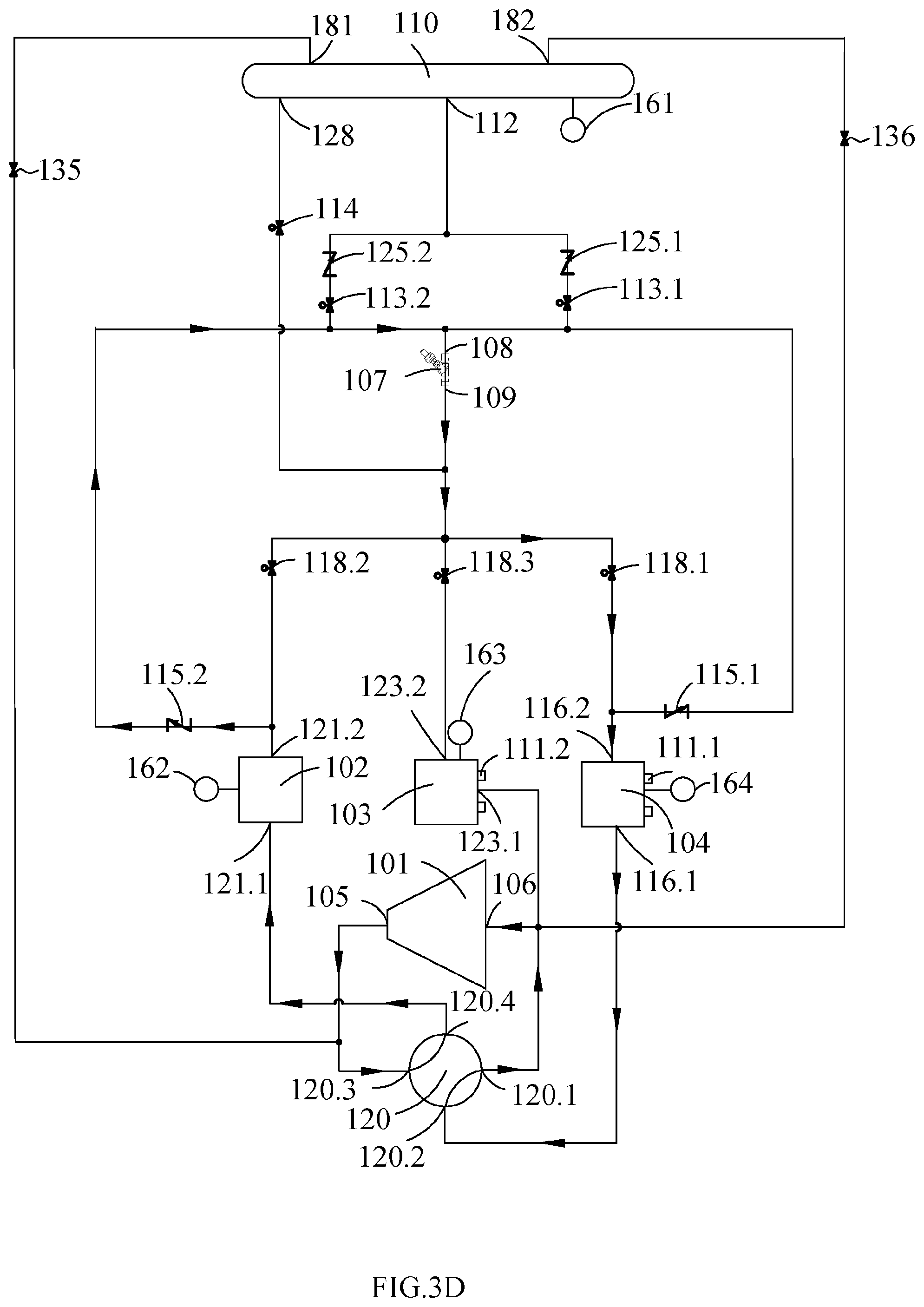
[0034] FIG. 3D is a block diagram illustrating the refrigerant circulation loops of the heat pump unit of FIG. 1 operating in the defrosting mode, according to some embodiments;
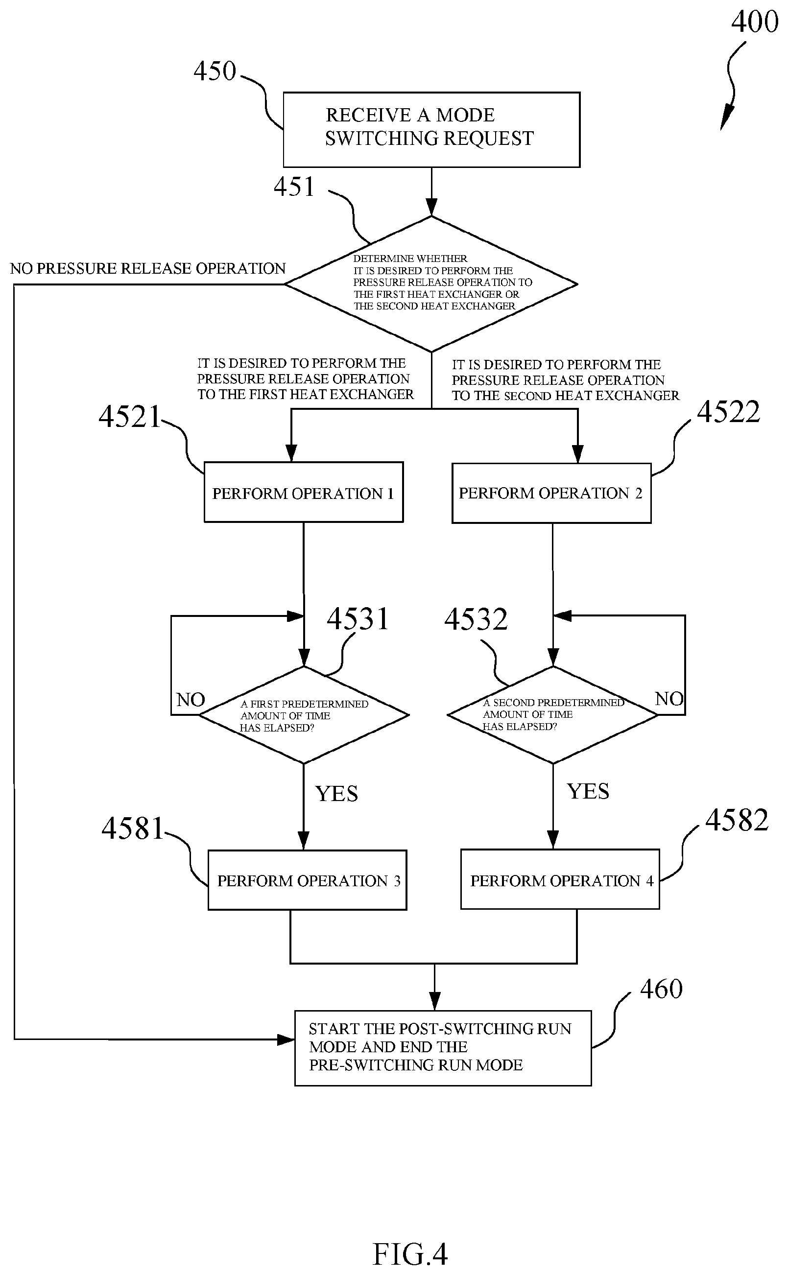
[0035] FIG. 4 is a process flow diagram illustrating a method of switching the run mode of the heat pump unit of FIG. 1, according to some embodiments;
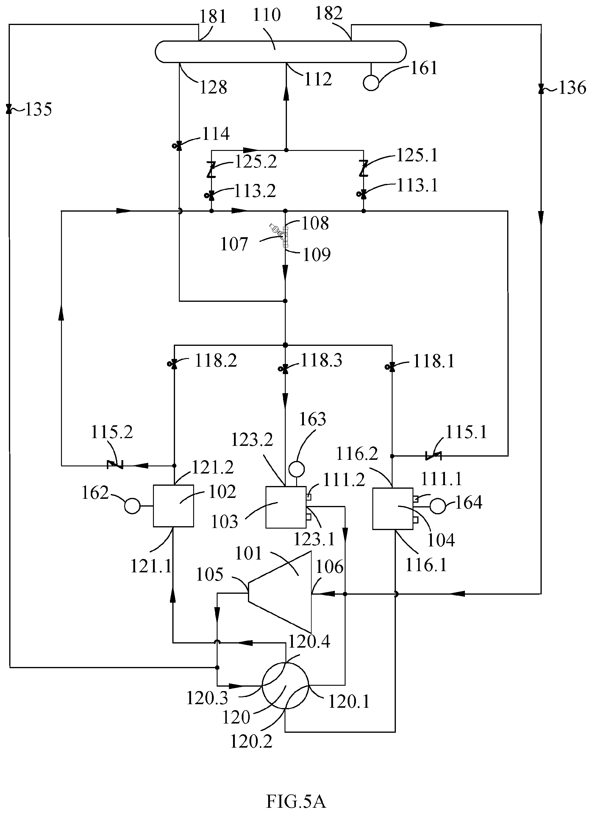
[0036] FIG. 5A is a block diagram illustrating the flow path of refrigerant when switching the run mode of the heat pump unit of FIG. 1 from a cooling mode to a cooling plus heating mode, according to some embodiments;
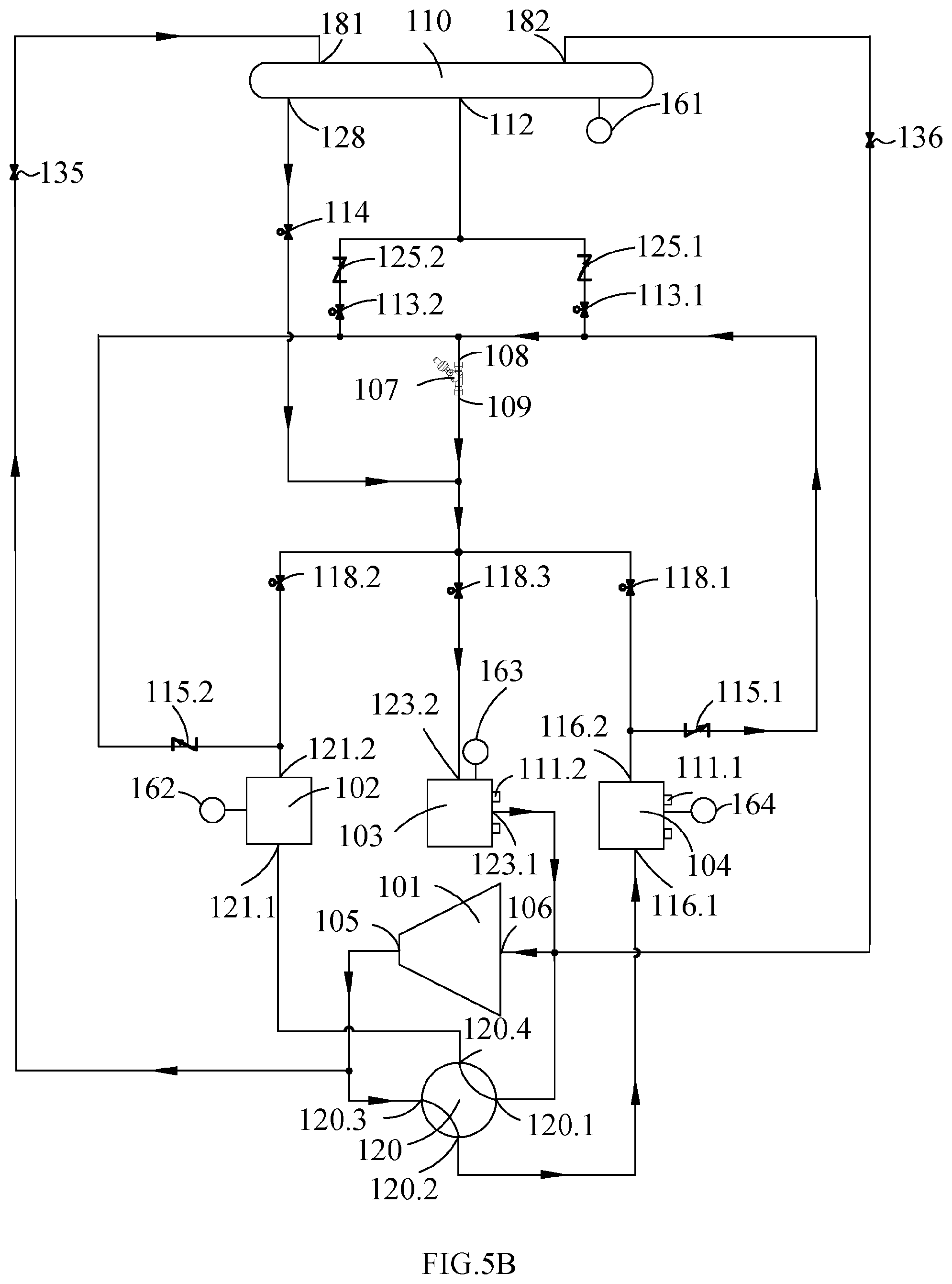
[0037] FIG. 5B is a block diagram illustrating the flow path of refrigerant when performing a refrigerant supplement operation to the refrigerant circulation loop of the heat pump unit of FIG. 1 running in the cooling plus heating mode, according to some embodiments;
[0038] FIG. 6 is a block diagram of a heat pump unit according to another embodiment of the present disclosure.
DETAILED DESCRIPTION
[0039] The following will describe various specific implementation modes of the present application by reference to the drawings which constitute a part of the present description. It should be understood that although the terms indicating directions, such as "before", "behind", "above", "below", "left", and "right" are used to describe various exemplified structural parts and components in the present application, these terms are just used for the convenience of illustrations and are determined based on the exemplified directions in the drawings. Since the embodiments disclosed in the present application can be set in different directions, these terms indicating directions are only used as illustrations, instead of restrictions.
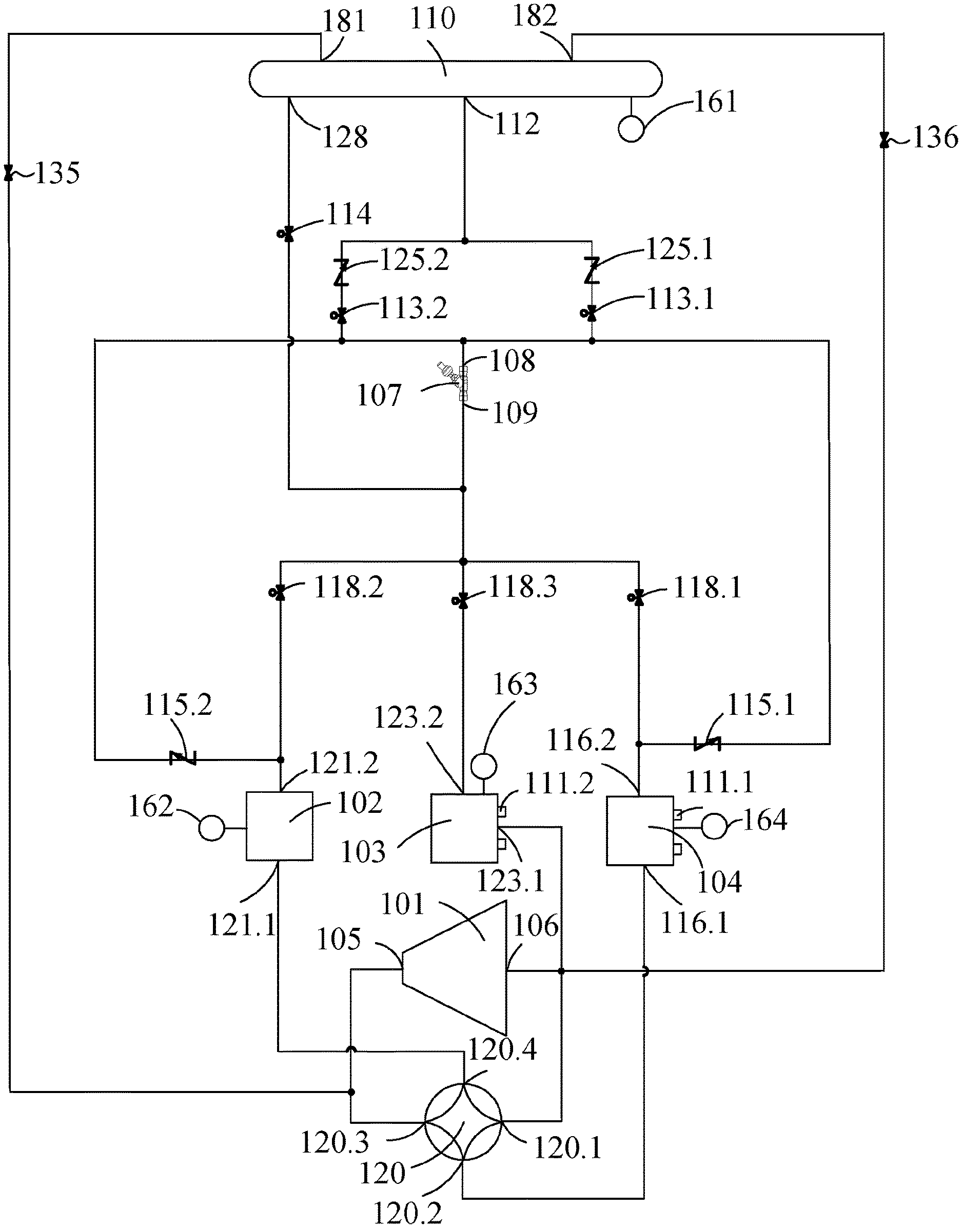
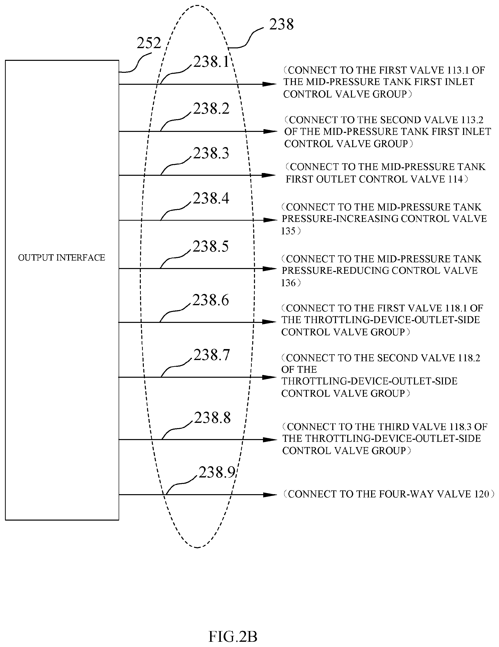
[0040] FIG. 1 is a block diagram of a heat pump unit according to an embodiment of the present disclosure. As shown in FIG. 1, the heat pump unit of the present disclosure comprises a compressor 101, a throttling device 107, a first heat exchanger 104, a second heat exchanger 102, a third heat exchanger 103, a mid-pressure tank 110, a four-way valve 120, and a plurality of other valves that will be introduced below. The connecting lines among the components (including the compressor 101, the throttling device 107, the first heat exchanger 104, the second heat exchanger 102, the third heat exchanger 103, the mid-pressure tank 110, the four-way valve 120, and the plurality of other valves) of FIG. 1 represents connecting pipelines. The compressor 101 has a suction end 106 and an exhaust end 105, and the suction end 106 and the exhaust end 105 are respectively connected to the four-way valve 120. The compressor 101 allows one-way flow of fluid from the suction end 106 to the exhaust end 105 thereof. The throttling device 107 has an inlet end 108 and an outlet end 109, and allows one-way flow of fluid from the inlet end 108 to the outlet end 109 thereof. In other embodiments, the four-way valve 120 can be replaced by other valves or valve groups. The four-way valve 120 shown in FIG. 1 has four interfaces, including a first interface 120.1, a second interface 120.2, a third interface 120.3, and a fourth interface 120.4. The first interface 120.1 is connected to the suction end 106 of the compressor 101, the third interface 120.3 is connected to the exhaust end 105 of the compressor 101, the second interface 120.2 is connected to the first heat exchanger 104, and the fourth interface 120.4 is connected to the second heat exchanger 102.
[0041] If the third interface 120.3 of the four-way valve 120 is connected to the second interface 120.2 and the first interface 120.1 is connected to the fourth interface 120.4, the exhaust end 105 of the compressor 101 is fluidly connected to the first heat exchanger 104 and the suction end 106 of the compressor 101 is fluidly connected to the second heat exchanger 102. In this way, the first heat exchanger 104 is capable of acting as a condenser located on the high-pressure side of the heat pump unit, while the second heat exchanger 102 is capable of being located on the low-pressure side of the heat pump unit.
[0042] If the third interface 120.3 of the four-way valve 120 is connected to the fourth interface 120.4 and the first interface 120.1 is connected to the second interface 120.2, the exhaust end 105 of the compressor 101 is fluidly connected to the second heat exchanger 102 and the suction end 106 of the compressor 101 is fluidly connected to the first heat exchanger 104. In this way, the second heat exchanger 102 is capable of acting as a condenser located on the high-pressure side of the heat pump unit, while the first heat exchanger 104 is capable of being located on the low-pressure side of the heat pump unit.
[0043] As shown in FIG. 1, the heat pump unit further comprises a third heat exchanger 103, and the third heat exchanger 103 is fluidly connected to the suction end 106 of the compressor 101. Therefore, the third heat exchanger 103 may be located on the low-pressure side of the heat pump unit and may not act as a condenser.
[0044] Still as shown in FIG. 1, the first heat exchanger 104, the second heat exchanger 102 and the third heat exchanger 103 each have at least two ports, wherein the first port 116.1 of the first heat exchanger 104 and the first port 121.1 of the second heat exchanger 102 are configured to connect to the four-way valve 120, and the first port 123.1 of the third heat exchanger 103 is configured to connect to the suction end 106 of the compressor 101. The heat pump unit further comprises a throttling-device-inlet-side control valve group 115.1,115.2 and a throttling-device-outlet-side control valve group 118.1,118.2,118.3.
[0045] The first heat exchanger 104 further has a second port 116.2. The second port 116.2 is fluidly connected to the inlet end 108 of the throttling device 107 via a first valve 115.1 of the throttling-device-inlet-side control valve group and the second port 116.2 is fluidly connected to the outlet end 109 of the throttling device 107 via a first valve 118.1 of the throttling-device-outlet-side control valve group, so that the second port 116.2 can act as not only the inlet of the first heat exchanger 104 to receive the refrigerant flowing out of the outlet end 109 of the throttling device 107, but also the outlet of the first heat exchanger 104 to supply the refrigerant to the inlet end 108 of the throttling device 107. Therefore, the first heat exchanger 104 allows controllable two-way flow of fluid from the first port 116.1 to the second port 116.2 thereof or from the second port 116.2 to the first port 116.1 thereof.
[0046] Similar to the first heat exchanger 104, the second heat exchanger 102 also has a second port 121.2. The second port 121.2 is fluidly connected to the inlet end 108 of the throttling device 107 via a second valve 115.2 of the throttling-device-inlet-side control valve group and is fluidly connected to the outlet end 109 of the throttling device 107 via a second valve 118.2 of the throttling-device-outlet-side control valve group. Therefore, the second heat exchanger 102 allows controllable two-way flow of fluid from the first port 121.1 to the second port 121.2 thereof or from the second port 121.2 to the first port 121.1 thereof.
[0047] The third heat exchanger 103 also has a second port 123.2, but the second port 123.2 of the third heat exchanger 103 is only fluidly connected to the outlet end 109 of the throttling device 107 via a third valve 118.3 of the throttling-device-outlet-side control valve group.
[0048] In the embodiment shown in FIG. 1, the throttling device 107 is an expansion valve, the high-pressure refrigerant goes from the inlet end 108 into the expansion valve 107 and is changed into a low-pressure refrigerant, and the low-pressure refrigerant is then discharged from the outlet end 109. Thus, in order to let the refrigerant in the first heat exchanger 104 and the second heat exchanger 102 controllably flow to the inlet end 108 of the throttling device 107, the first valve 115.1 and the second valve 115.2 of the throttling-device-inlet-side control valve group can be solenoid valves or one-way valves. For example, the first valve 115.1 and the second valve 115.2 of the throttling-device-inlet-side control valve group in the embodiment shown in FIG. 1 are one-way valves so that much more cost can be saved. The refrigerant in the first heat exchanger 104 can flow to the inlet end 108 of the throttling device 107 when the one-way valve 115.1 is opened, and the refrigerant in the second heat exchanger 102 can flow to the inlet end 108 of the throttling device 107 when the one-way valve 115.2 is opened.
[0049] The one-way valves are automatically opened and closed due to the pressure difference across the one-way valves without the need of being controlled by the control device 230 as shown in FIG. 2A. However, according to the present disclosure, the first valve 115.1 and the second valve 115.2 of the throttling-device-inlet-side control valve group can also be solenoid valves which are connected to and controlled by the control device 230 as shown in FIG. 2A. The first valve 118.1, the second valve 118.2 and the third valve 118.3 of the throttling-device-outlet-side control valve group can be solenoid valves, so that the refrigerant flowing out of the outlet end 109 of the throttling device 107 can controllably flow into the required heat exchanger(s). For example, if the first valve 118.1 of the throttling-device-outlet-side control valve group is opened and the second valve 118.2 and the third valve 118.3 of the throttling-device-outlet-side control valve group are closed, the refrigerant flowing out of the outlet end 109 of the throttling device 107 can flow into the first heat exchanger 104.
[0050] The first heat exchanger 104, the second heat exchanger 102 and the third heat exchanger 103 as mentioned above can be different types of heat exchangers, for example, air heat exchangers exchanging heat with air or waterside heat exchangers exchanging heat with water. As an exemplified embodiment, the second heat exchanger 102 is an air heat exchanger not connected to the working end, while the first heat exchanger 104 and the third heat exchanger 103 are waterside heat exchangers and are respectively connected to first water supply and return pipe 111.1 and second water supply and return pipe 111.2 so that the heat exchangers can supply the heating load or cooling load required on the user side when exchanging heat. As another example, the heat pump unit of the present application can include more than three heat exchangers.
[0051] Still as shown in FIG. 1, the heat pump unit further comprises a mid-pressure tank 110. The mid-pressure tank 110 is a container used to store the refrigerant. The refrigerant can be a refrigerant liquid, or a refrigerant gas, or a mixture of the gas and liquid of a refrigerant. The mid-pressure tank 110 has a mid-pressure tank first inlet 112 and a mid-pressure tank first outlet 128, wherein the mid-pressure tank first inlet 112 is fluidly connected to the heat exchangers (i.e., the first heat exchanger 104 and the second heat exchanger 102) which are capable of acting as condensers via a mid-pressure tank first inlet control valve group 113.1, 113.2.
[0052] In the embodiment shown in FIG. 1, the mid-pressure tank first inlet 112 is respectively fluidly connected to the second port 116.2 of first heat exchanger 104 and the second port 121.2 of the second heat exchanger 102 via a first valve 113.1 and a second valve 113.2 of the mid-pressure tank first inlet control valve group. As an example, the mid-pressure tank first inlet 112 is connected to the fluid path between the first valve 115.1 of the throttling-device-inlet-side control valve group and the inlet end 108 of the throttling device 107 via the first valve 113.1 of the mid-pressure tank first inlet control valve group and is connected to the fluid path between the second valve 115.2 of the throttling-device-inlet-side control valve group and the inlet end 108 of the throttling device 107 via the second valve 113.2 of the mid-pressure tank first inlet control valve group. Thus, the high-pressure refrigerant in the first heat exchanger 104 and the second heat exchanger 102 can flow into the mid-pressure tank 110 by controlling the throttling-device-inlet-side control valve group 115.1, 115.2 and the mid-pressure tank first inlet control valve group 113.1, 113.2. As another example, there can be a plurality of shown mid-pressure tank first inlets 112 and each inlet is respectively fluidly connected to the heat exchanger which is capable of acting as a condenser via its corresponding first inlet control valve. In another embodiment, the mid-pressure tank first inlet control valve group is provided with only one valve through which the mid-pressure tank first inlet 112 is connected to the inlet end 108 of the throttling device 107.
[0053] In the mid-pressure tank 110 shown in FIG. 1, the mid-pressure tank first outlet 128 is fluidly connected to the low-pressure side of the running heat pump unit via a mid-pressure tank first outlet control valve 114, and thus the refrigerant in the mid-pressure tank 110 can flow into the refrigerant circulation loop to supplement refrigerant to the refrigerant circulation loop. The mid-pressure tank first outlet 128 is fluidly connected to the second port 116.2 of the first heat exchanger 104, the second port 121.2 of the second heat exchanger 102, and the second port 123.2 of the third heat exchanger 103 via the mid-pressure tank first outlet control valve 114. To improve the running stability of the heat pump unit, the mid-pressure tank first outlet control valve 114 can be an expansion valve to ensure that the refrigerant flowing out of the mid-pressure tank first outlet 128 can be changed into a low-pressure refrigerant and then the low-pressure refrigerant flows into the low-pressure side of the running heat pump unit. As an example, the mid-pressure tank first outlet 128 is fluidly connected to the outlet end 109 of the throttling device 107 via the mid-pressure tank first outlet control valve 114. The mid-pressure tank first inlet 112 and the mid-pressure tank first outlet 128 are mainly used for delivery of the refrigerant liquid such that they are provided at the bottom of the mid-pressure tank 110.
[0054] The heat pump unit further comprises a mid-pressure tank pressure-increasing control valve 135 and a mid-pressure tank pressure-reducing control valve 136. The mid-pressure tank 110 is further provided with a mid-pressure tank second inlet 181 and a mid-pressure tank second outlet 182. As an example, the mid-pressure tank second inlet 181 is connected to the fluid path between the exhaust end 105 of the compressor 101 and the four-way valve 120 via the mid-pressure tank pressure-increasing control valve 135, and the mid-pressure tank second outlet 182 is connected to the suction end 106 of the compressor 101 via the mid-pressure tank pressure-reducing control valve 136. The mid-pressure tank first inlet 112 and the mid-pressure tank first outlet 128 are mainly used for delivery of the refrigerant gas such that they are provided at the top of the mid-pressure tank 110.
[0055] The mid-pressure tank 110 receives the high-pressure refrigerant discharged from the heat exchangers which are capable of acting as condensers via the mid-pressure tank first inlet 112 so that the refrigerant and pressure in the heat exchangers are reduced but the refrigerant and pressure in the mid-pressure tank 110 are increased. The mid-pressure tank 110 can also supplement a refrigerant to the refrigerant circulation loop of the heat pump unit through the mid-pressure tank first outlet 128. If the pressure is too high in the mid-pressure tank 110, the pressure can be reduced by delivery of the refrigerant gas in the mid-pressure tank 110 to the suction end 106 of the compressor 101 by opening the mid-pressure tank pressure-reducing control valve 136. If the pressure in the mid-pressure tank 110 is too low, the pressure can be increased by delivery of the high-pressure refrigerant gas from the exhaust end 105 of the compressor 101 to the mid-pressure tank 110 by opening the mid-pressure tank pressure-increasing control valve 135. Thus, the pressure in the mid-pressure tank 110 can be maintained within a desired range.
[0056] To further guarantee the flow direction of the fluid in the mid-pressure tank 110, as an example, a first one-way valve 125.1 can be provided between the first valve 113.1 of the mid-pressure tank first inlet control valve group and the mid-pressure tank first inlet 112, and a second one-way valve 125.2 can be provided between the second valve 113.2 of the mid-pressure tank first inlet control valve group and the mid-pressure tank first inlet 112. The first one-way valve 125.1 will be automatically opened when the first valve 113.1 of the mid-pressure tank first inlet control valve group is opened, and the second one-way valve 125.2 will be automatically opened when the second valve 113.2 of the mid-pressure tank first inlet control valve group is opened. A one-way valve (not shown) can also be provided in the downstream fluid path of the mid-pressure tank first outlet control valve 114.
[0057] Still as shown in FIG. 1, a pressure sensor 161 is provided in the mid-pressure tank 110 for detecting the pressure in the mid-pressure tank 110. Pressure sensors 164, 162, and 163 are provided in the first heat exchanger 104, the second heat exchanger 102 and the third heat exchanger 103, respectively, for detecting the pressure therein.
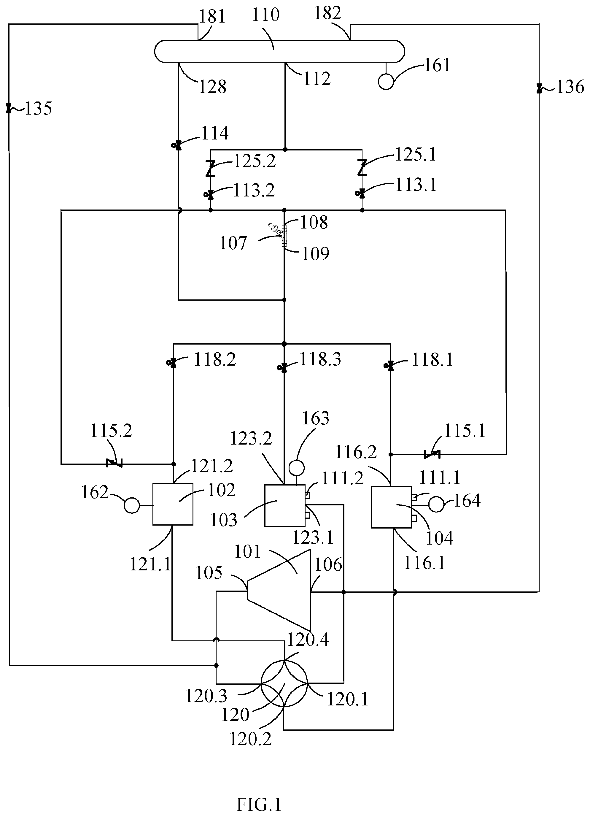
[0058] The heat pump unit further comprises a control device 230 (as shown in FIG. 2), and all the pressure sensors and control valves in FIG. 1 are connected to the control device 230. FIGS. 2A, 2B, and 2C are block diagrams for the control device 230 of the heat pump unit as shown in FIG. 1. As shown in FIG. 2A, the control device 230 comprises a bus 242, a processor 244, an input interface 248, an output interface 252 and a memory 254 in which programs 256 and data 257 are stored. The processor 244, the input interface 248, the output interface 252 and the memory 254 are communicatively connected to the bus 242 so that the processor 244 can control the operation of the input interface 248, the outlet interface 252 and the memory 254. Specifically, the memory 254 is configured for storing the programs 256, instructions and data 257, the processor 244 can read the programs 256, instructions and data 257 from the memory 254 and can write data into the memory 254.
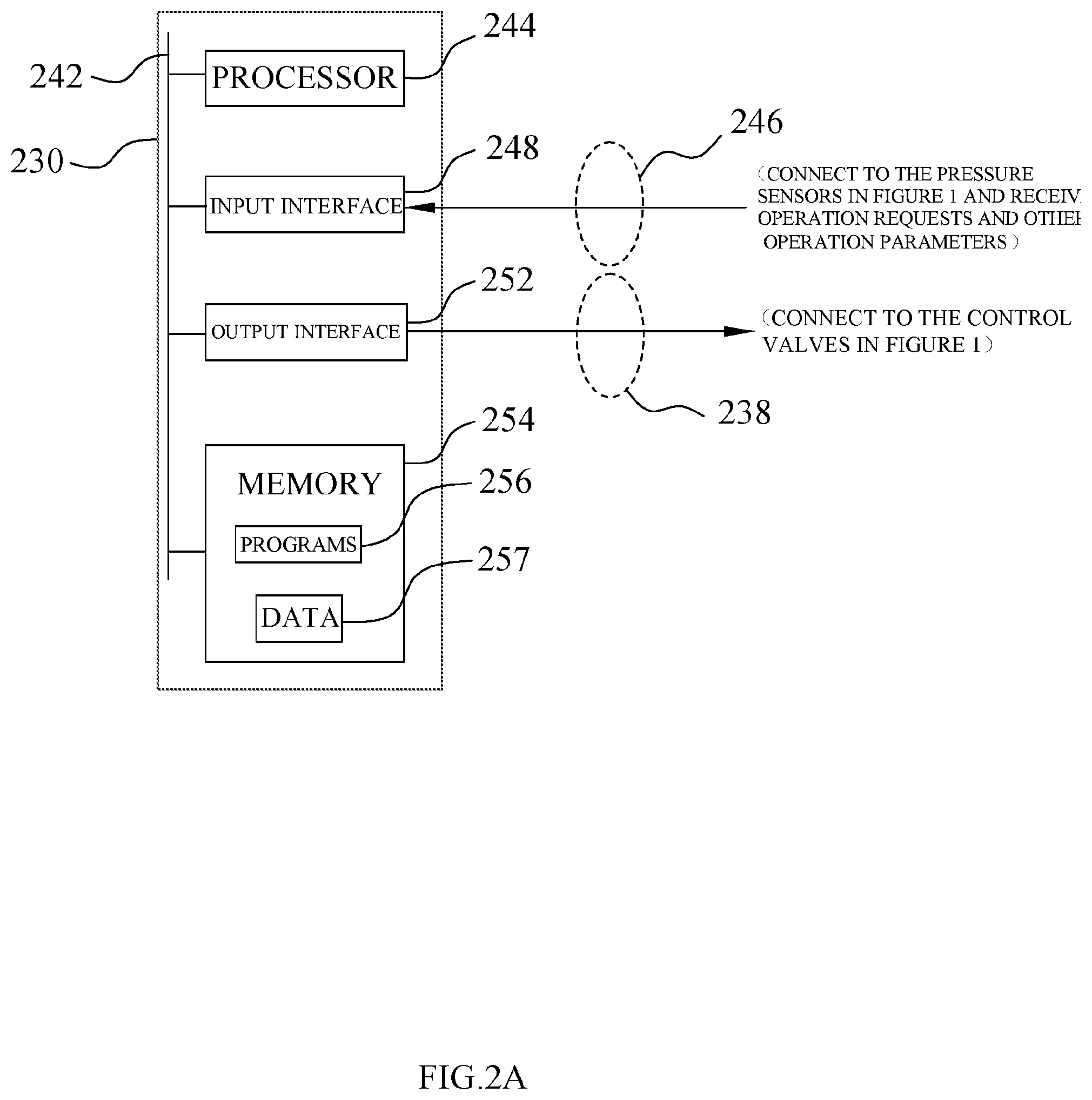
[0059] As shown in FIG. 2B, the output interface 252 is connected through the connections 238 (238.1, 238.2, 238.3 . . . 238.9) to all the control valves in FIG. 1, including the first valve 113.1 and second valve 113.2 of the mid-pressure tank first inlet control valve group, the mid-pressure tank first outlet control valve 114, the mid-pressure tank pressure-increasing control valve 135, the mid-pressure tank pressure-reducing control valve 136, the first valve 118.1, the second valve 118.2 and the third valve 118.3 of the throttling-device-outlet-side control valve group, and the four-way valve 120.
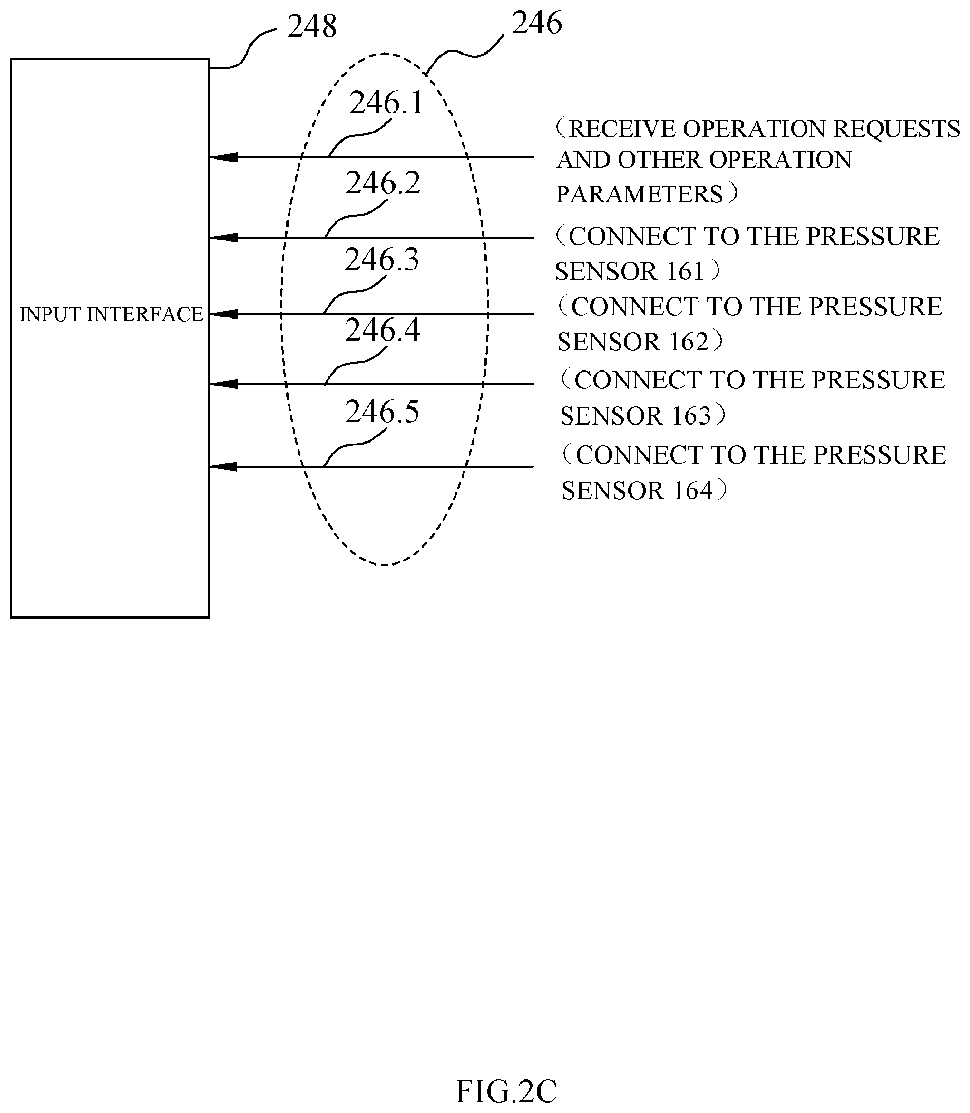
[0060] As shown in FIG. 2C, the input interface 248 is connected through the connections 246.2, 246.3, 246.4, and 246.5 to the pressure sensors 161, 162, 163, and 164, respectively, and receive through the connection 246.1 operation requests to the heat pump unit and other operation parameters. The processor 244 can control the operation of the heat pump unit of the present disclosure by performing reading the programs and the instructions via the memory 254.
[0061] More specifically, the control device 230 can receive the operation requests from the heat pump unit (for example, the requests sending from a control panel), the operation parameters sending from the pressure sensors as shown in FIG. 1 and other operation parameters of the heat pump unit via the input interface 248, and send control signals via the output interface 252 to the control valves in FIG. 1. By controlling the control valves in FIG. 1, the heat pump unit is capable of running in multiple modes and being switched between the multiple modes.
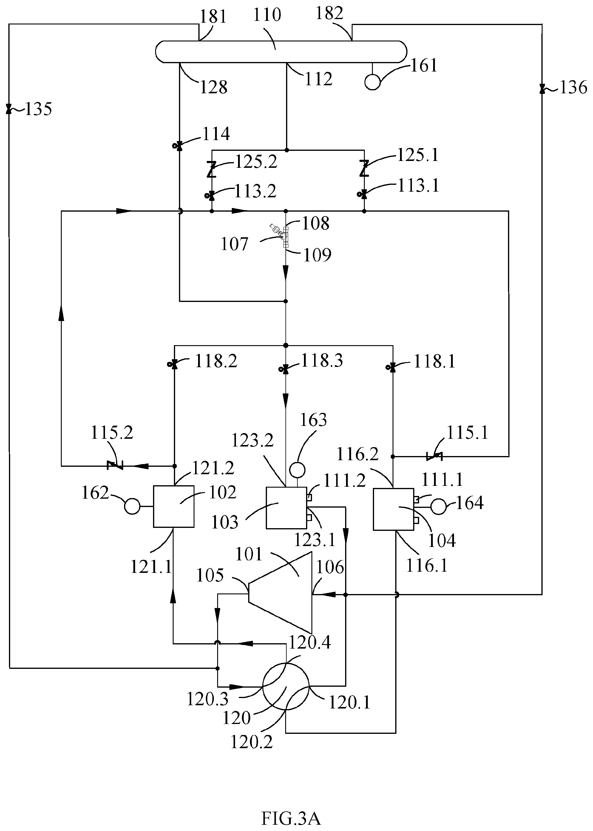
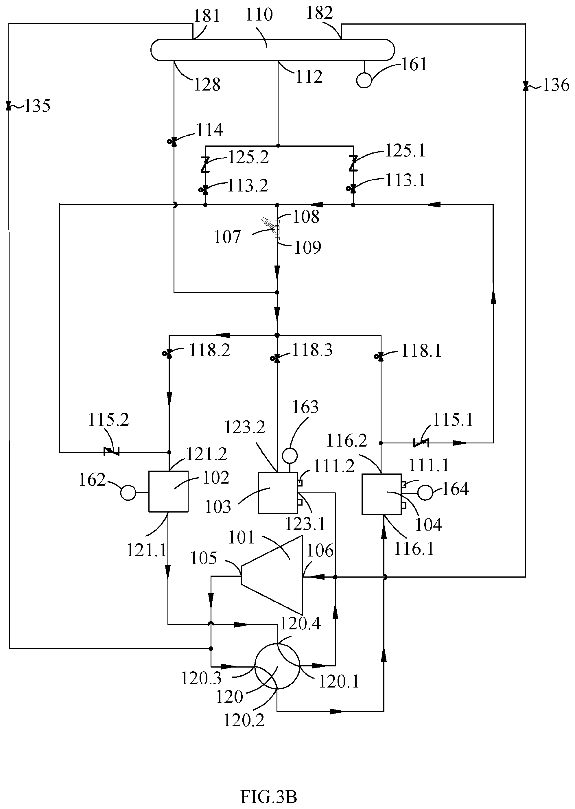
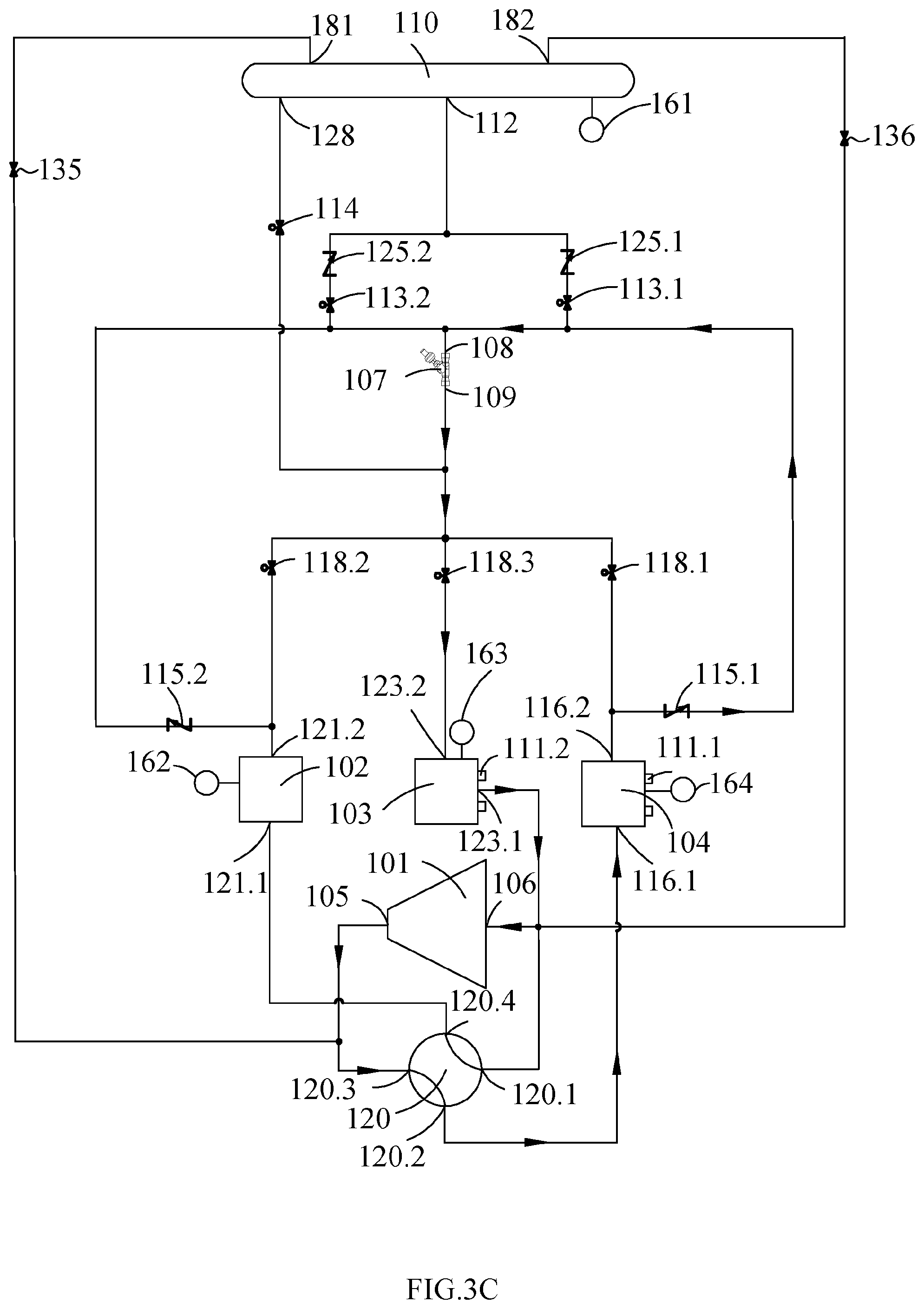
[0062] FIGS. 3A-3D illustrate the refrigerant circulation loops of the heat pump unit of FIG. 1 running in four modes, respectively, wherein the arrows indicate the flow directions and flow paths of the refrigerant. FIG. 3A illustrates the refrigerant circulation loop in a cooling only mode (Mode 1), FIG. 3B illustrates the refrigerant circulation loop in a heating only mode (Mode 2), FIG. 3C illustrates the refrigerant circulation loop in a cooling plus heating mode (Mode 3), while FIG. 3D illustrates the refrigerant circulation loop in a defrosting mode (Mode 4).
[0063] Table 1 lists the status of the first valve 118.1, the second valve 118.2, and the third valve 118.3 of the throttling-device-outlet-side control valve group, and the four-way valve 120 for the multiple modes of the heat pump unit. Table 1 can be stored in the storage 254 as shown in FIG. 2A.
TABLE-US-00001 TABLE 1 Status of Valves for Various Heat Pump Unit Modes Four-way valve Throttling-device-outlet-side control valve Mode 120 118.1 118.2 118.3 Cooling only Powered off Closed Closed Open mode Heating only Powered on Closed Open Closed mode Cooling plus Powered on Closed Closed Open heating mode Defrosting Powered off Open Closed Closed mode
[0064] In Table 1, when the four-way valve 120 is powered on, the third interface 120.3 and the second interface 120.2 of the four-way valve 120 are connected, while the first interface 120.1 and the fourth interface 120.4 are connected. When the four-way valve 120 is powered off, the third interface 120.3 and the fourth interface 120.4 of the four-way valve 120 are connected, while the first interface 120.1 and the second interface 120.2 are connected.
[0065] The heat pump unit of the present disclosure is capable of running in the following modes by connecting two of the three heat exchangers with the compressor 101 and the throttling device 107 to form the refrigerant circulation loop, while leaving the third of the heat exchangers connected in parallel with the one, which is on the low-pressure side, of the two heat exchangers in the refrigerant circulation loop for spare use and for start in other modes.
[0066] Mode 1: Cooling Only
[0067] As shown in FIG. 3A and Table 1, if it is desired to run the heat pump unit in the cooling only mode, controlling, via the control device 230, the four-way valve 120 to power off it such that the third interface 120.3 and the fourth interface 120.4 of the four-way valve 120 are connected while the first interface 120.1 and the second interface 120.2 are connected, and controlling, via the control device 230, the third valve 118.3 of the throttling-device-outlet-side control valve group to open it. The second valve 115.2 of the throttling-device-inlet-side control valve group can be automatically opened since it is a one-way valve. The other valves are closed. In this way, the high-pressure refrigerant discharged from the exhaust end 105 of the compressor 101 first passes through the second heat exchanger 102, then flows through the second valve 115.2 of the throttling-device-inlet-side control valve group into the inlet end 108 of the throttling device 107 and is changed into a low-pressure refrigerant, then the low-pressure refrigerant flows through the third valve 118.3 of the throttling-device-outlet-side control valve group into the third heat exchanger 103, and finally the refrigerant flows from the third heat exchanger 103 to the suction end 106 of the compressor 101 to complete the circulation of the refrigerant.
[0068] In the cooling only mode, the compressor 101, the throttling device 107, the second heat exchanger 102 and the third heat exchanger 103 are in the refrigerant circulation loop, the second heat exchanger 102 acts as a condenser, and the third heat exchanger 103 acts as an evaporator and cools externally via the second water supply and return pipe 111.2. The first heat exchanger 104 is for spare use and is connected in parallel with the third heat exchanger 103, and the first heat exchanger 104 is not in the refrigerant circulation loop.
[0069] Mode 2: Heating Only
[0070] As shown in FIG. 3B and Table 1, if it is desired to run the heat pump unit in the heating only mode, controlling, via the control device 230, the four-way valve 120 to power on it such that the third interface 120.3 and the second interface 120.2 of the four-way valve 120 are connected while the first interface 120.1 and the fourth interface 120.4 are connected, and controlling, via the control device 230, the second valve 118.2 of the throttling-device-outlet-side control valve group to open it. The first valve 115.1 of the throttling-device-inlet-side control valve group can be automatically opened since it is a one-way valve. The other valves are closed. In this way, the high-pressure refrigerant discharged from the exhaust end 105 of the compressor 101 first passes through the first heat exchanger 104, then flows through the first valve 115.1 of the throttling-device-inlet-side control valve group into the inlet end 108 of the throttling device 107 and is changed into a low-pressure refrigerant, then the low-pressure refrigerant flows through the second valve 118.2 of the throttling-device-outlet-side control valve group into the second heat exchanger 102, and finally the refrigerant flows from the second heat exchanger 102 to the suction end 106 of the compressor 101 to complete the circulation of the refrigerant.
[0071] In the heating only mode, the compressor 101, the throttling device 107, the first heat exchanger 104 and the second heat exchanger 102 are in the refrigerant circulation loop, the first heat exchanger 104 acts as a condenser and heats externally via the first water supply and return pipe 111.1, and the second heat exchanger 102 acts as an evaporator. The third heat exchanger 103 is for spare use and is connected in parallel with the second heat exchanger 102, and the third heat exchanger 103 is not in the refrigerant circulation loop.
[0072] Mode 3: Cooling Plus Heating
[0073] As shown in FIG. 3C and Table 1, if it is desired to run the heat pump unit in the cooling plus heating mode, controlling, via the control device 230, the four-way valve 120 to power on it such that the third interface 120.3 and the second interface 120.2 of the four-way valve 120 are connected while the first interface 120.1 and the fourth interface 120.4 are connected, and controlling, via the control device 230, the third valve 118.3 of the throttling-device-outlet-side control valve group to open it. The first valve 115.1 of the throttling-device-inlet-side control valve group can be automatically opened since it is a one-way valve. The other valves are closed. In this way, the high-pressure refrigerant discharged from the exhaust end 105 of the compressor 101 first passes through the first heat exchanger 104, then flows through the first valve 115.1 of the throttling-device-inlet-side control valve group into the inlet end 108 of the throttling device 107 and is changed into a low-pressure refrigerant, then the low-pressure refrigerant flows through the third valve 118.3 of the throttling-device-outlet-side control valve group into the third heat exchanger 103, and finally the refrigerant flows from the third heat exchanger 103 to the suction end 106 of the compressor 101 to complete the circulation of the refrigerant.
[0074] In the cooling plus heating mode, the compressor 101, the throttling device 107, the first heat exchanger 104 and the third heat exchanger 103 are in the refrigerant circulation loop, the first heat exchanger 104 acts as a condenser and heats externally via the first water supply and return pipe 111.1, and the third heat exchanger 103 acts as an evaporator and cools externally via the second water supply and return pipe 111.2. The second heat exchanger 102 is for spare use and is connected in parallel with the third heat exchanger 103, and the second heat exchanger 102 is not in the refrigerant circulation loop.
[0075] Mode 4: Defrosting
[0076] When the heat pump unit runs in the heating only mode and the ambient temperature is low, the surface of the second heat exchanger 102 as an air heat exchanger will be frosted and it is desired to defrost the surface by heating it.
[0077] As shown in FIG. 3D and Table 1, if it is desired to run the heat pump unit in the defrosting mode, controlling, via the control device 230, the four-way valve 120 to power off it such that the third interface 120.3 and the fourth interface 120.4 of the four-way valve 120 are connected while the first interface 120.1 and the second interface 120.2 are connected, and controlling, via the control device 230, the first valve 118.1 of the throttling-device-outlet-side control valve group to open it. The second valve 115.2 of the throttling-device-inlet-side control valve group can be automatically opened since it is a one-way valve. The other valves are closed. In this way, the high-pressure refrigerant discharged from the exhaust end 105 of the compressor 101 first passes through the second heat exchanger 102, then flows through the second valve 115.2 of the throttling-device-inlet-side control valve group into the inlet end 108 of the throttling device 107 and is changed into a low-pressure refrigerant, then the low-pressure refrigerant flows through the first valve 118.1 of the throttling-device-outlet-side control valve group into the first heat exchanger 104, and finally the refrigerant flows from the first heat exchanger 104 to the suction end 106 of the compressor 101 to complete the circulation of the refrigerant.
[0078] In the defrosting mode, the compressor 101, the throttling device 107, the first heat exchanger 104 and the second heat exchanger 102 are in the refrigerant circulation loop, the second heat exchanger 102 acts as a condenser and heats externally so that the second heat exchanger 102 is defrosted, and the first heat exchanger 104 acts as an evaporator. The third heat exchanger 103 is for spare use and is connected in parallel with the first heat exchanger 104, and the third heat exchanger 103 is not in the refrigerant circulation loop.
[0079] During the running of the heat pump unit in any of above-mentioned modes, if the degree of super-cooling of the refrigerant in the condenser is too high, the corresponding valve 113.1 or 113.2 in the mid-pressure tank first inlet control valve group of the heat exchanger acting as the condenser is opened and the redundant refrigerant in the heat exchanger acting as the condenser is discharged into the mid-pressure tank 110; if the degree of super-cooling is not too high, the corresponding valve 113.1 or 113.2 in the mid-pressure tank first inlet control valve group is closed and the discharge of redundant refrigerant stops. If the pressure in the low-pressure side of the running heat pump unit is too low, the mid-pressure tank first outlet control valve 114 is opened and the refrigerant in the mid-pressure tank 110 flows to the low-pressure side of the running system via the mid-pressure tank first outlet control valve 114 to supplement refrigerant; if the pressure is no longer too low, the mid-pressure tank first outlet control valve 114 is closed and refrigerant supplementation stops. The closing and opening of the valve 113.1 or 113.2 and the valve 114 are controlled by the control device 230.
[0080] If the run mode of the heat pump unit is switched among the aforementioned multiple modes, a pressure release operation may be desired in some situations to the first heat exchanger 104 or the second heat exchanger 102 which is capable of acting as a condenser. Specifically, when a heat exchanger acting as a condenser in a pre-switching run mode does not act as a condenser in a post-switching run mode, then it is desired to perform the pressure release operation.
[0081] Table 2 is the mode switching table for the heat pump unit of FIG. 1. Whether a pressure release operation is desired during the mode switching is summarized in Table 2. The activated valves in each mode are also summarized in Table 2. The contents in Table 2 are stored in the storage 254 as shown in FIG. 2A. The processer 244 can determine whether it is desired to perform a pressure release operation to the first heat exchanger 104 or the second heat exchanger 102 by reading Table 2 after receiving a request of switching the current run mode (i.e., a pre-switching run mode) of the heat pump unit to a post-switching run mode.
TABLE-US-00002 TABLE 2 Status of Valves During Switching of Heat Pump Unit Modes Activated valves Activated valves Activated valves Pre-switching in the pre- Post-switching in the post- in the pressure run mode switching run mode run mode switching run mode release operation Cooling 118.3 Heating only 120/118.2 113.2 only Cooling plus 120/118.3 113.2 heating Heating 120/118.2 Cooling only 118.3 113.1 only Cooling plus 120/118.3 No pressure heating release operation Defrosting 118.1 113.1 Cooling 120/118.3 Cooling only 118.3 113.1 plus heating Heating only 120/118.2 No pressure release operation Defrosting 118.1 Heating only 120/118.2 113.2
[0082] In Table 2, the four-way valve 120 is powered on when it is activated and the control valves 118.1, 118.2, 118.3, 113.1 and 113.2 are opened when they are activated. The specific pressure release operations to the heat exchangers may be described as Operation 1, Operation 2, Operation 3, and Operation 4. Each of Operations 1-4 is described in further detail below.
[0083] Operation 1 may include fluidly connecting the first heat exchanger 104 to the mid-pressure tank first inlet 112 so as to discharge the refrigerant from the first heat exchanger 104 to the mid-pressure tank 110. Operation 1 corresponds to opening the valve 113.1 (i.e., the first valve 113.1 of the mid-pressure first inlet control valve group) in Table 2.
[0084] Operation 2 may include fluidly connecting the second heat exchanger 102 to the mid-pressure tank first inlet 112 so as to discharge the refrigerant from the second heat exchanger 102 to the mid-pressure tank 110. Operation 2 corresponds to opening the valve 113.2 (i.e., the second valve 113.2 of the mid-pressure first inlet control valve group) in Table 2.
[0085] As indicated in Table 2, when it is desired to switch the run mode of the heat pump unit from the cooling only mode (the pre-switching run mode) to the heating only mode or the cooling plus heating mode (the post-switching run mode), it is desired to perform the pressure release operation to the second heat exchanger 102 since the second heat exchanger 102 acting as a condenser in the cooling only mode does not act as a condenser in the heating only mode or the cooling plus heating mode. The desired pressure release operation to the second heat exchanger 102 is Operation 2.
[0086] When it is desired to switch the run mode of the heat pump unit from the heating only mode (the pre-switching run mode) to the cooling only mode or the defrosting mode (the post-switching run mode), it is desired to perform the pressure release operation to the first heat exchanger 104 since the first heat exchanger 104 acting as a condenser in the heating only mode does not act as a condenser in the cooling only mode or the defrosting mode. The desired pressure release operation to the first heat exchanger 104 is Operation 1.
[0087] When it is desired to switch the run mode of the heat pump unit from the cooling plus heating mode (the pre-switching run mode) to the cooling only mode (the post-switching run mode), it is desired to perform the pressure release operation to the first heat exchanger 104 since the first heat exchanger 104 acting as a condenser in the cooling plus heating mode does not act as a condenser in the cooling only mode. The desired pressure release operation to the first heat exchanger 104 is Operation 1.
[0088] When it is desired to switch the run mode of the heat pump unit from the defrosting mode (the pre-switching run mode) to the heating only mode (the post-switching run mode), it is desired to perform the pressure release operation to the second heat exchanger 102 since the second heat exchanger 102 acting as a condenser in the defrosting mode does not act as a condenser in the heating only mode. The desired pressure release operation to the second heat exchanger 102 is Operation 2.
[0089] Still as indicated in Table 2, when it is desired to switch the run mode of the heat pump unit between the heating only mode and the cooling plus heating mode, no pressure release operation is desired since the first heat exchanger 104 acts as a condenser in both of the two modes.
[0090] Referring now to FIG. 4, a process flow diagram illustrating a method 400 of switching the run mode for the heat pump unit of FIG. 1 is depicted. The steps of the method 400 as shown are stored in the storage 254 of the control device 230 and performed by the control device 230.
[0091] Process 400 may commence with step 450. Step 450 may include receiving a mode switching request, namely a request for switching the run mode of the heat pump unit from the pre-switching run mode to the post-switching run mode. The control device 230 receives the mode switching request via the input interface 248. The mode switching request is, for example, inputted by an operator via a user interface connecting to the input interface 248, or automatically sent from the heat pump unit according to the operation parameters.
[0092] Process 400 may continue with step 451. Step may include determining whether it is desired to perform the pressure release operation to the first heat exchanger 104 or the second heat exchanger 102. The control device 230 determines, according to Table 2 stored in the storage 254, whether it is desired to perform the pressure release operation to the first heat exchanger 104 or the second heat exchanger 102 if the run mode of the heat pump unit is to be switched from the pre-switching run mode to the requested post-switching run mode. The control device 230 turns to Step 4521 if it is determined that it is desired to perform the pressure release operation to the first heat exchanger 104, turns to Step 4522 if it is determined that it is desired to perform the pressure release operation to the second heat exchanger 102, and turns to Step 460 if it is determined that no pressure release operation is desired to the first heat exchanger 104 or the second heat exchanger 102.
[0093] Step 4521 may include performing the aforementioned Operation 1 and then turning to Step 4531. By performing Operation 1, the first valve 113.1 of the mid-pressure first inlet control valve group is opened such that the first heat exchanger 104 is fluidly connected to the mid-pressure first inlet 112 to discharge the refrigerant in the first heat exchanger 104 into the mid-pressure tank 110.
[0094] Step 4522 may include performing the aforementioned Operation 2 and then turning to Step 4532. By performing Operation 2, the second valve 113.2 of the mid-pressure first inlet control valve group is opened such that the second heat exchanger 102 is fluidly connected to the mid-pressure first inlet 112 to discharge the refrigerant in the second heat exchanger 102 into the mid-pressure tank 110.
[0095] Step 4531 may include determining whether a first predetermined amount of time has elapsed since Operation 1 is performed. If yes, it is considered that the pressure release operation may be ended and the control device 230 turns to Step 4581. If not, the control device 230 continues to perform Step 4531 until it is determined that the first predetermined amount of time has elapsed. The first predetermined amount of time can be determined according to the cooling capacity/heating capacity of the heat pump unit. As an example, the first predetermined amount of time is about 30-60 seconds.
[0096] Step 4532 may include determining whether a second predetermined amount of time has elapsed since Operation 2 is performed. If yes, it is considered that the pressure release operation may be ended and the control device 230 turns to Step 4582. If not, the control device 230 continues to perform Step 4532 until it is determined that the second predetermined amount of time has elapsed. The second predetermined amount of time can be also determined according to the cooling capacity/heating capacity of the heat pump unit. As an example, the second predetermined amount of time is about 30-60 seconds. The second predetermined amount of time can be the same as or different from the first predetermined amount of time.
[0097] Step 4581 may include performing Operation 3, namely, disconnecting the first heat exchanger 104 from the mid-pressure first inlet 112, and then turning to Step 460. Operation 3 corresponds to closing the valve 113.1 (i.e., the first valve 113.1 of the mid-pressure first inlet control valve group).
[0098] Step 4582 may include performing Operation 4, namely, disconnecting the second heat exchanger 102 from the mid-pressure first inlet 112, and then turning to Step 460. Operation 4 corresponds to closing the valve 113.2 (i.e., the second valve 113.2 of the mid-pressure first inlet control valve group).
[0099] Process 400 may conclude with step 460. Step 460 may include starting the post-switching run mode and ending the pre-switching run mode to finish the mode switching. In Step 460, the post-switching run mode is started by activating the corresponding valves which may be activated in the post-switching run mode. The valves to be activated for each kind of post-switching run mode are summarized in Table 2. Specifically, the valve 120 (i.e., the four-way valve 120) and the valve 118.2 (i.e., the second valve 118.2 of the throttling-device-outlet-side control valve group) will be activated if the post-switching run mode is the heating only mode, the valve 118.3 (i.e., the third valve 118.3 of the throttling-device-outlet-side control valve group) will be activated if the post-switching run mode is the cooling only mode, the valve 120 (i.e., the four-way valve 120) and the valve 118.3 (i.e., the third valve 118.3 of the throttling-device-outlet-side control valve group) will be activated if the post-switching run mode is the cooling plus heating mode, and the valve 118.1 (i.e., the first valve 118.1 of the throttling-device-outlet-side control valve group) will be activated if the post-switching run mode is the defrosting mode.
[0100] In Step 460, the pre-switching run mode is ended by deactivating the corresponding valves which are activated in the pre-switching run mode. The valves activated for each kind of pre-switching run mode are summarized in Table 2. Specifically, the valve 120 and the valve 118.2 will be deactivated if the pre-switching run mode is the heating only mode, and the valve 118.3 will be deactivated if the pre-switching run mode is the cooling only mode, the valve 120 and the valve 118.3 will be deactivated if the pre-switching run mode is the cooling plus heating mode, and the valve 118.1 will be activated if the pre-switching run mode is the defrosting mode.
[0101] It should be noted that even though starting the post-switching run mode and ending the pre-switching run mode are performed in the same Step 460, the pre-switching run mode can be ended after a certain time delay from starting the post-switching run mode in other embodiments according to the present disclosure.
[0102] According to the present disclosure, the control device 230 is further configured to perform Operation 5, namely, fluidly connecting the mid-pressure tank first outlet 128 and the outlet end 109 of the throttling device 107, if it is desired to supplement refrigerant to the refrigerant circulation loop of the post-switching run mode after the post-switching run mode is started. Operation 5 corresponds to opening the mid-pressure tank first outlet control valve 114. The control device 230 is further configured to fluidly connecting the mid-pressure second inlet 181 to the exhaust end 105 of the compressor 101 by opening the mid-pressure tank pressure-increasing control valve 135 if the pressure sensor 161 detects that the pressure in the mid-pressure tank 110 is below a first predetermined pressure value during performing Operation 5. In this way, the pressure in the mid-pressure tank 110 can be increased to ensure that the refrigerant in the mid-pressure tank 110 can be supplemented into the refrigerant circulation loop. As an example, the control device 230 is configured to close the mid-pressure tank pressure-increasing control valve 135 if the pressure in the mid-pressure tank 110 is increased above the pressure at the mid-pressure first outlet 128.
[0103] According to the present disclosure, the control device 230 is further configured to fluidly connecting the mid-pressure tank second outlet 182 to the suction end 106 of the compressor 101 by opening the mid-pressure tank pressure-reducing control valve 136 if the pressure sensor 161 detects that the pressure in the mid-pressure tank 110 is above a second predetermined pressure value during performing Operation 1 or Operation 2. In this way, the pressure in the mid-pressure tank 110 can be reduced to ensure that the high-pressure refrigerant in the first heat exchanger 104 or the second heat exchanger 102 can be discharged into the mid-pressure tank 110. As an example, the control device 230 is configured to close the mid-pressure tank pressure-reducing control valve 136 if the pressure in the mid-pressure tank 110 is reduced below the pressure at the mid-pressure first inlet 112.
[0104] The aforementioned first predetermined pressure value and second predetermined pressure value can be determined according to the desired range of value for the pressure in the mid-pressure tank 110.
[0105] Furthermore, according to the present disclosure, to further ensure the effectiveness of the mode switching, the control device 230 is further configured to determine whether the pressure in the heat exchanger to which the pressure release operation has been performed is still high by detecting the pressure of the refrigerant in the heat exchanger with the corresponding pressure sensor 164/162. If yes, it is considered that the mode switching fails and then the control device 230 stops the heat pump unit.
[0106] FIG. 5A illustrates the flow path of the refrigerant when switching the run mode of the heat pump unit of FIG. 1 from the cooling only mode to the cooling plus heating mode. The following describes how to release pressure from the heat exchanger that needs pressure release by taking some of the operations for switching the run mode of the heat pump unit from the cooling only mode to the cooling plus heating mode as an example.
[0107] If the run mode of the heat pump unit is to be switched from the cooling only mode as shown in FIG. 3A to the cooling plus heating mode as shown in FIG. 3C, the second heat exchanger 102 will be switched from the heat exchanger acting as a condenser on the high-pressure side to a spare heat exchanger, and therefore pressure release is desired to the second heat exchanger 102.
[0108] As shown in FIG. 5A, when the heat pump unit is still running in the cooling only mode, the second valve 113.2 of the mid-pressure tank first inlet control valve group is first opened to fluidly connect the second heat exchanger 102 to the mid-pressure tank first inlet 112 so that the high-pressure refrigerant in the second heat exchanger 102 can be discharged into the mid-pressure tank 110.
[0109] The pressure release operation to the second heat exchanger 102 as shown in FIG. 5A will be ended after the second predetermined amount of time has elapsed. To end the pressure release operation, the second valve 113.2 of the mid-pressure tank first inlet control valve group will be closed to disconnect the second port 121.2 of the second heat exchanger 102 from the mid-pressure tank first inlet 112. After that, the run mode will be switched from the cooling only mode to the cooling plus heating mode by controlling the four-way valve 120 to power on it, so as to connect the third interface 120.3 and the second interface 120.2 of the four-way valve 120 and connect the fourth interface 120.4 and the first interface 120.1. Since the third valve 118.3 of the throttling-device-outlet-side control valve group is opened in both of the cooling only mode and the cooling plus heating mode, the switching to the cooling plus heating mode can be completed without any operation to the third valve 118.3.
[0110] FIG. 5B illustrates the flow path of the refrigerant when performing refrigerant supplement operation to the refrigerant circulation loop of the heat pump unit of FIG. 1 running in the cooling plus heating mode.
[0111] The refrigerant circulation loop of the heat pump unit may need the refrigerant supplement operation when it is normally running in the four modes. For example, after the run mode of the heat pump unit is switched from the cooling only mode as shown in FIG. 5A to the cooling plus heating mode as shown in FIG. 5B, the refrigerant circulation loop in the cooling plus heating mode may need refrigerant supplement due to the pressure release operation as shown in FIG. 5A. To this end, as shown in FIG. 5B, the mid-pressure first outlet control valve 114 is opened to fluidly connect the mid-pressure first outlet 128 to the outlet end 109 of the throttling device 107 so that the refrigerant in the mid-pressure tank 110 can be supplemented into the refrigerant circulation loop. In the meantime, if the pressure in the mid-pressure tank 110 is not enough, the mid-pressure tank pressure-increasing control valve 135 is opened to fluidly connect the mid-pressure second inlet 181 to the exhaust end 105 of the compressor 101 so as to increase the pressure in the mid-pressure tank 110 to ensure that the refrigerant in the mid-pressure tank 110 can be supplemented into the refrigerant circulation loop.
[0112] By performing the pressure release operation to the heat exchanger which needs the operation during mode switching, on the one hand, the pressure shock caused when the heat exchanger on the high-pressure side is switched to be a heat exchanger on the low-pressure side at the time of mode switching can be prevented, and on the other hand, the residual liquid refrigerant in the heat exchanger on the high-pressure side is not enough to be brought from the suction end into the compressor to cause a liquid shock after mode switching. Furthermore, by performing the mode switching method of the present disclosure, on the one hand, since the pressure difference during pressure release is very small, the vibration intensity during pressure release is also very small, and on the other hand, the switching time is very short and the corresponding shock force is also small. Therefore, this switching process can be considered smoother and more efficient than a conventional shutdown switching process.
[0113] As an example, if it is desired to switch the run modes, the load of the compressor 101 can first be reduced so that the refrigerant participating in the refrigerant circulation of the heat pump unit is reduced, and the refrigerant can be discharged into the mid-pressure tank 110 as much as possible. In addition, by reducing the suction volume and discharge volume of the compressor, the corresponding shock force at the time of mode switching will also be very small.
[0114] In addition, through the receiving and supplementing of the refrigerant by the mid-pressure tank 110, the shock caused by a pressure jump at the time of mode switching on the heat pump unit can be reduced, the service lives of the components can be prolonged, and the running reliability and stability of the heat pump unit can be improved. In addition, through the reasonable control of the refrigerant in the refrigerant circulation loop of the heat pump unit running in a normal run mode by the mid-pressure tank 110, the reliability and the energy efficiency ratio of the heat pump unit can be improved.
[0115] FIG. 6 is a block diagram of the heat pump unit according to another embodiment of the present application. To further improve the energy efficiency ratio and the running stability of the heat pump unit, the embodiment of the heat pump unit as shown in FIG. 6 is provided. The embodiment as shown in FIG. 6 includes all the components in FIG. 1 and is further provided with an oil separator 630, a drying filter 632 and an economizer 634 based on the heat pump unit of FIG. 1.
[0116] As shown in FIG. 6, the oil separator 630 is located between the exhaust end 105 of the compressor 101 and the four-way valve 120 and is configured to separate the oil discharged from the compressor 101. The drying filter 632 is located at the upstream side of the inlet end 108 of the throttling device 107 and the drying filter 632 is configured to dry and filter the high-pressure refrigerant before the high-pressure refrigerant flows into the throttling device 107. The economizer 634 is located at the downstream side of the drying filter 632. The outlet of the drying filter 632 is connected to the liquid inlet on the super-cooling side of the economizer 634, the liquid outlet on the super-cooling side of the economizer 634 is connected to the inlet end 108 of the throttling device 107, and the gas outlet of the economizer 634 is connected to the gas replenishing port of the compressor 101. Thus, the degree of super-cooling of the system, the gas delivery capacity, and the performance of the heat pump unit can further be improved.
[0117] Although the present disclosure is described by reference to the specific implementation modes shown in the drawings, it should be understood that the heat pump unit in the present disclosure can have many variants, without departing from the spirit, scope and background of the present application. Those skilled in the art should also realize that different changes to the structural details in the embodiments disclosed in the present application should all fall within the spirit and scope of the present application and the claims.
* * * * *
D00000
D00001
D00002
D00003
D00004
D00005
D00006
D00007
D00008
D00009
D00010
D00011
D00012
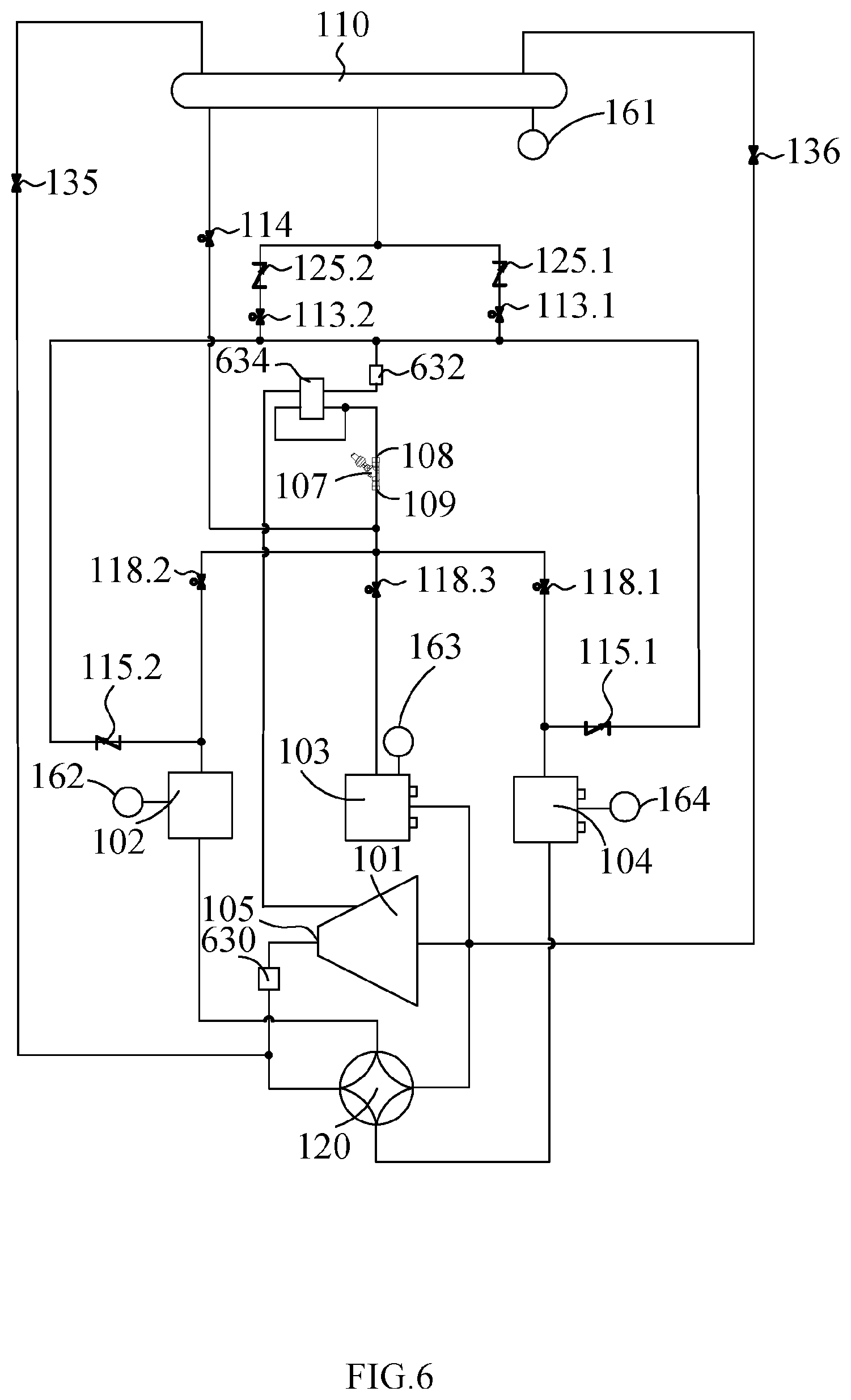
XML
uspto.report is an independent third-party trademark research tool that is not affiliated, endorsed, or sponsored by the United States Patent and Trademark Office (USPTO) or any other governmental organization. The information provided by uspto.report is based on publicly available data at the time of writing and is intended for informational purposes only.
While we strive to provide accurate and up-to-date information, we do not guarantee the accuracy, completeness, reliability, or suitability of the information displayed on this site. The use of this site is at your own risk. Any reliance you place on such information is therefore strictly at your own risk.
All official trademark data, including owner information, should be verified by visiting the official USPTO website at www.uspto.gov. This site is not intended to replace professional legal advice and should not be used as a substitute for consulting with a legal professional who is knowledgeable about trademark law.