Central Lock For Folding Tent
SUN; Yuanru ; et al.
U.S. patent application number 16/642013 was filed with the patent office on 2020-07-30 for central lock for folding tent. This patent application is currently assigned to ZHEJIANG JIANSHENG LEISURE PRODUCTS CO.,LTD. The applicant listed for this patent is ZHEJIANG JIANSHENG LEISURE PRODUCTS CO.,LTD. Invention is credited to Jian HE, Yuanru SUN, Qiwang YING, Chao ZENG.
| Application Number | 20200240167 16/642013 |
| Document ID | 20200240167 / US20200240167 |
| Family ID | 1000004813993 |
| Filed Date | 2020-07-30 |
| Patent Application | download [pdf] |


View All Diagrams
| United States Patent Application | 20200240167 |
| Kind Code | A1 |
| SUN; Yuanru ; et al. | July 30, 2020 |
CENTRAL LOCK FOR FOLDING TENT
Abstract
A central lock for a folding tent includes a central lock rod, an upper lock plate fixedly disposed at one end of the central lock rod, and a lower lock plate assembly detachably connected to the other end of the central lock rod. An elastic locking member and an unlocking mechanism used to control the elastic locking member to be locked are disposed in the lower lock plate assembly. The elastic locking member includes an arc-shaped portion provided integrally and two horizontal locking rods extending inwards from a gap of the arc-shaped portion. A lower end portion of the central lock rod is provided with a locking groove used in cooperation with the locking rod and a clamping and locking portion located at a lower end of the locking groove.
| Inventors: | SUN; Yuanru; (Zhejiang, CN) ; ZENG; Chao; (Zhejiang, CN) ; YING; Qiwang; (Zhejiang, CN) ; HE; Jian; (Zhejiang, CN) | ||||||||||
| Applicant: |
|
||||||||||
|---|---|---|---|---|---|---|---|---|---|---|---|
| Assignee: | ZHEJIANG JIANSHENG LEISURE PRODUCTS
CO.,LTD Zhejiang CN |
||||||||||
| Family ID: | 1000004813993 | ||||||||||
| Appl. No.: | 16/642013 | ||||||||||
| Filed: | August 15, 2019 | ||||||||||
| PCT Filed: | August 15, 2019 | ||||||||||
| PCT NO: | PCT/CN2019/100687 | ||||||||||
| 371 Date: | February 25, 2020 |
| Current U.S. Class: | 1/1 |
| Current CPC Class: | E04H 15/50 20130101 |
| International Class: | E04H 15/50 20060101 E04H015/50 |
Foreign Application Data
| Date | Code | Application Number |
|---|---|---|
| Aug 6, 2019 | CN | 201921262392.3 |
Claims
1. A central lock for a folding tent, the central lock comprising a central lock rod, an upper lock plate fixedly disposed at one end of the central lock rod, and a lower lock plate assembly (3) detachably connected to the other end of the central lock rod, wherein an elastic locking member and an unlocking mechanism used to control the elastic locking member to be locked are disposed in the lower lock plate assembly, the elastic locking member comprises an arc-shaped portion provided integrally and two horizontal locking rods extending inwards from a gap of the arc-shaped portion, and a lower end portion of the central lock rod is provided with a locking groove used in cooperation with the locking rods and a clamping and locking portion located at a lower end of the locking groove.
2. The central lock for the folding tent according to claim 1, wherein the lower lock plate assembly comprises an upper plate, an intermediate plate, and a lower plate, the upper plate is hingedly connected to a short tent bone, the upper plate is fixedly connected to the intermediate plate by a screw, a space used to place the elastic locking member (4) is disposed between the intermediate plate and the upper plate, the lower plate is sleeved on a lower end of the intermediate plate, guiding columns are symmetrically disposed on an outer wall of the lower end of the intermediate plate, and a guiding trough is provided at locations, corresponding to the guiding columns, of an inner wall of the lower plate; the unlocking mechanism comprises an unlocking block and an unlocking column fixedly disposed at a lower end of the unlocking block, the unlocking column extends through the intermediate plate to the lower plate and is then fixed by a screw, the unlocking block is in trapezoid shape, an upper end of the unlocking block has a width larger than that of the lower end of the unlocking block, and in a locked state, the low er end of the unlocking block is clamped at the gap of the elastic locking member.
3. The central lock for the folding tent according to claim 1, wherein the lower lock plate assembly comprises an upper plate and a central base, the upper plate and the central base are fixedly connected by a screw, a space used to place the elastic locking member is provided between the upper plate and an upper portion of the central base, and the unlocking mechanism extends through the central base to lock the elastic locking member.
4. The central lock for the folding tent according to claim 3, wherein the unlocking mechanism comprises an unlocking block, an unlocking column disposed at a lower end of the unlocking block, a compression spring sleeved on the unlocking column, a button cover, and an inclined conical surface block, the bottom cover is clamped on a bottom portion of the central base, the unlocking column is fixed on the button cover after extending through the central base, a cross section of the unlocking block is a triangle and a surface of an end of the unlocking block is arc-shaped, an intermediate portion of the arc-shaped portion of the elastic locking member abuts on an upper end of an arc-shaped surface of the unlocking block, and the inclined conical surface block is correspondingly disposed at the gap of the elastic locking member.
5. The central lock for the folding tent according to claim 3, wherein the unlocking mechanism comprises a columnar unlocking block, an unlocking column disposed at a lower portion of the columnar unlocking block, a compression spring, a pull ring, a pull ring fixing block, and an inclined conical surface block, the pull ring fixing block is fixedly disposed at a bottom portion of the central base, the compression spring is sleeved on the unlocking column, the pull ring is disposed at an end portion of the unlocking column after the unlocking column extends through the pull ring fixing block, a side surface of the columnar unlocking block is provided with an arc-shaped gap, an intermediate portion of the arc-shaped portion of the elastic locking member (4) abuts on a lower end of the arc-shaped gap, and the inclined conical surface block is correspondingly disposed at the gap of the elastic locking member.
6. The central lock for the folding tent according to claim 1, wherein a width of an end, of the inclined conical surface block, close to the gap of the elastic locking member is smaller, and a width of an end far away from the gap of the locking member is larger
7. The central lock for the folding tent according to claim 4, wherein the inclined conical surface block is disposed on a bottom surface of the upper plate or a surface of an upper end of the central base.
8. The central lock for the folding tent according to claim 2, wherein the lower lock plate assembly comprises the upper plate and a rotary base, a central shaft of a hollow structure is disposed on a lower bottom surface of the upper plate, a center hole through which the central shaft extends is provided on the rotary base, two outer annular installation grooves that are spaced apart are formed on an outer wall of the rotary base, two inner annular installation grooves are formed at locations, corresponding to the two outer annular installation grooves, of an outer wall of the central shaft, outer limit blocks are disposed between the two outer annular installation grooves, inner limit blocks are disposed between the two inner annular installation grooves, and after the elastic locking member enters from the outer annular installation grooves, outer sides of the gap of the elastic locking member respectively abut on the two outer limit blocks, and the two locking rods respectively abut on the two inner limit blocks.
9. The central lock for the folding tent according to claim 8, wherein a width between the two locking rods is not less than a width between the inner limit blocks.
10. The central lock for the folding tent according to claim 5, wherein a width of an end, of the inclined conical surface block, close to the gap of the elastic locking member is smaller, and a width of an end far away from the gap of the locking member is larger
11. The central lock for the folding tent according to claim 5, wherein the inclined conical surface block is disposed on a bottom surface of the upper plate or a surface of an upper end of the central base
Description
[0001] portion, a lower end portion of the central lock rod is provided with a locking groove used in cooperation with the locking rods and a clamping and locking portion located at a lower end of the locking groove, and specifically, the locking rods are clamped in the locking groove to implement locking.
[0002] The lower lock plate assembly includes an upper plate, an intermediate plate, and a lower plate. The upper plate is hingedly connected to a short tent bone, and the upper plate is fixedly connected to the intermediate plate by a screw. A space used to place the elastic locking member is disposed between the intermediate plate and the upper plate, the lower plate is sleeved on a lower end of the intermediate plate, guiding columns are symmetrically disposed on an outer wall of the lower end of the intermediate plate, and a guiding trough is provided at locations, corresponding to the guiding columns, of an inner wall of the lower plate. The unlocking mechanism includes an unlocking block and an unlocking column fixedly disposed at a lower end of the unlocking block, the unlocking column extends through the intermediate plate to the lower plate and is then fixed by a screw, the unlocking block is in a trapezoid shape with a wider upper width and a narrower lower width. In a locked state, a narrow portion of the lower end of the unlocking block is clamped at the gap of the elastic locking member.
[0003] The lower lock plate assembly includes an upper plate and a central base, the upper plate and the central base are fixedly connected by a screw, a space used to place the elastic locking member is provided between the upper plate and an upper portion of the central base, and the unlocking mechanism extends through the central base to lock the elastic locking member.
[0004] The unlocking mechanism includes an unlocking block, an unlocking column fixedly disposed at a lower end of the unlocking block, a compression spring sleeved on the unlocking column, a button cover, and an inclined conical surface block, the bottom cover is clamped on a bottom portion of the central base, the unlocking column is fixed on the button cover after extending through the central base, a cross section of the unlocking block is a triangle and a surface of an end of the unlocking block is arc-shaped, an intermediate portion of the arc-shaped portion of the elastic locking member abuts on an upper end of an arc-shaped surface of the unlocking block, and the inclined conical surface block is correspondingly disposed at the gap of the elastic locking member.
[0005] The unlocking mechanism includes a columnar unlocking block, an unlocking column disposed at a lower portion of the columnar unlocking block, a compression spring, a pull ring, a pull ring fixing block, and an inclined conical surface block, the pull ring fixing block is fixedly disposed at a bottom portion of the central base, the compression spring is sleeved on the unlocking column, the pull ring is disposed at an end portion of the unlocking column after the unlocking column extends through the pull ring fixing block, a side surface of the columnar unlocking block is provided with an arc-shaped gap, an intermediate portion of the arc-shaped portion of the elastic locking member abuts on a lower end of the arc-shaped gap, and the inclined conical surface block is correspondingly disposed at the gap of the elastic locking member.
[0006] A width of an end, of the inclined conical surface block, close to the gap of the elastic locking member is smaller, and a width of an end far away from the gap of the locking member is larger.
[0007] The inclined conical surface block is disposed on a bottom surface of the upper plate or a surface of an upper end of the central base.
[0008] The lower lock plate assembly includes an upper plate and a rotary base, a central shaft of a hollow structure is disposed on a lower bottom surface of the upper plate, a center hole through which the central shaft extends is provided on the rotary base, two outer annular installation grooves that are spaced apart are formed on an outer wall of the rotary base, two inner annular installation grooves are formed at locations, corresponding to the two outer annular installation grooves, of an outer wall of the central shaft, outer limit blocks are disposed between the two outer annular installation grooves, inner limit blocks are disposed between the two inner annular installation grooves, and after the elastic locking member enters from the outer annular installation grooves, outer sides of the gap of the elastic locking member respectively abut on the two outer limit blocks, and the two locking rods respectively abut on the two inner limit blocks.
[0009] A width between the two locking rods is not less than a width between the inner limit blocks.
[0010] The present invention has a simple structure and is easy to implement. A production and installation process is convenient and fast, and has low costs. In addition, the structure of the central lock is simple to operate, and a folding operation can be implemented by only performing pulling down or screwing after pushing up in one step. Therefore, the central lock is very convenient to use and is easy to promote and apply.
BRIEF DESCRIPTION OF THE DRAWINGS
[0011] FIG. 1 is a schematic structural diagram of an elastic locking member according to the present invention;
[0012] FIG. 2 is a schematic diagram of an entire structure of a central lock in an embodiment 1;
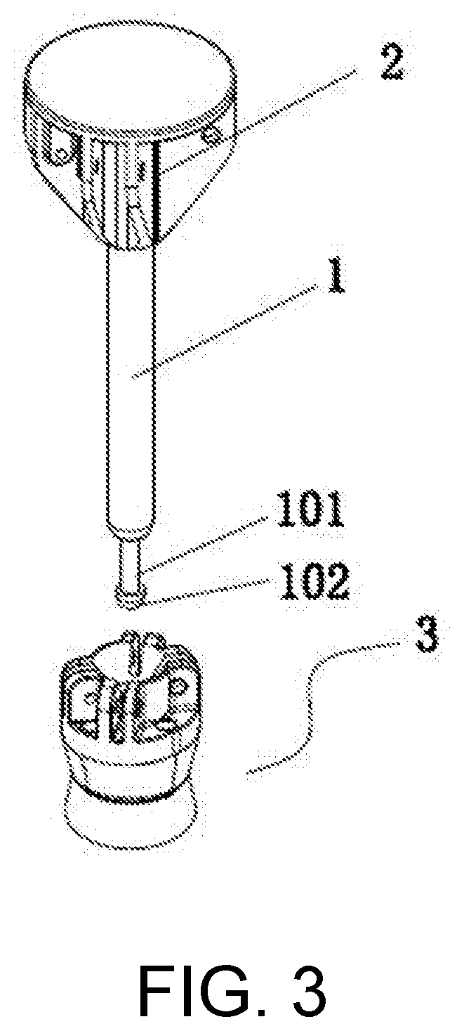
[0013] FIG. 3 is a schematic structural diagram when a lock plate in FIG. 2 is detached;
[0014] FIG. 4 is an expanded view of FIG. 2;
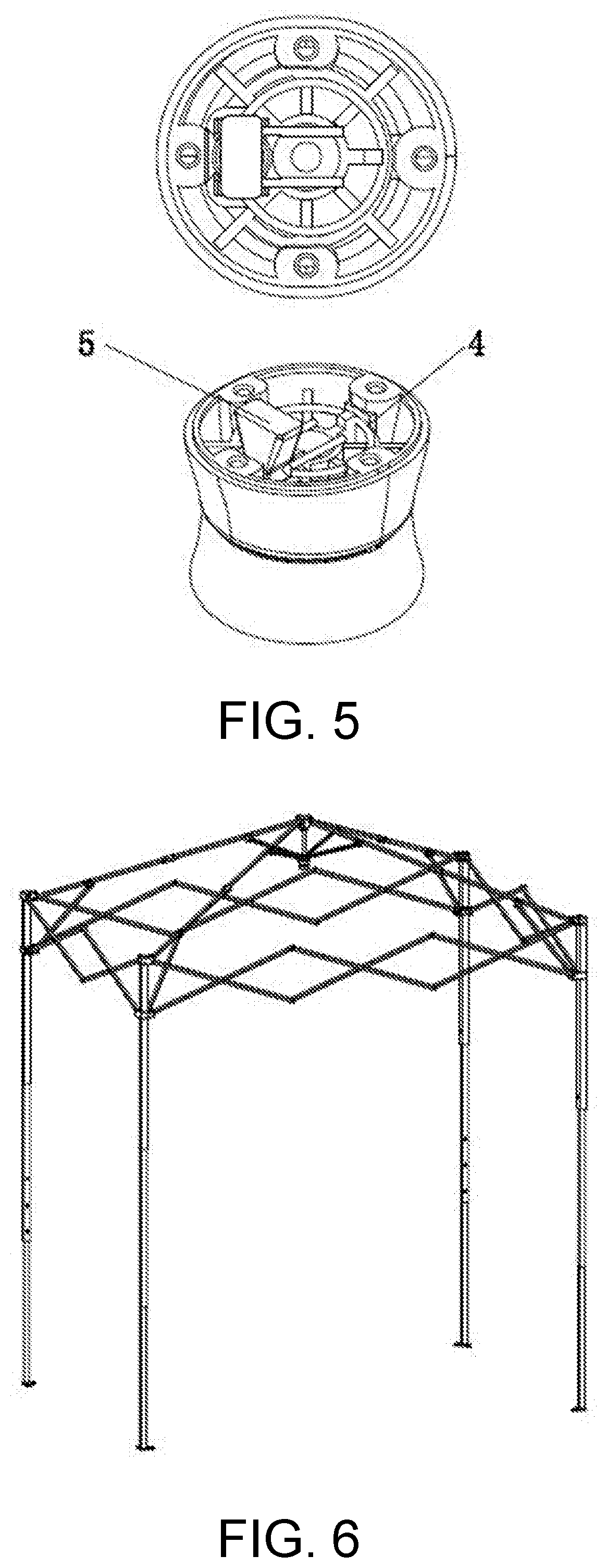
[0015] FIG. 5 is a schematic structural diagram of a lower lock plate assembly in the embodiment 1;
[0016] FIG. 6 is a schematic structural diagram when a central lock in the embodiment 1 is installed on a folding tent;
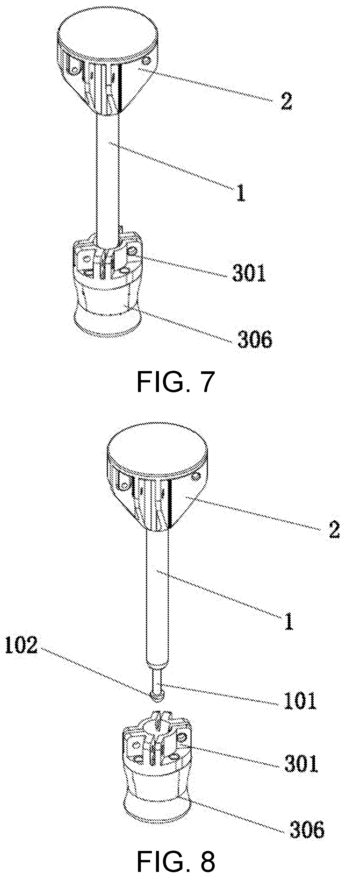
[0017] FIG. 7 is a schematic diagram of an entire structure of a central lock in an embodiment 2;
[0018] FIG. 8 is a schematic structural diagram when a lock plate in FIG. 7 is detached;
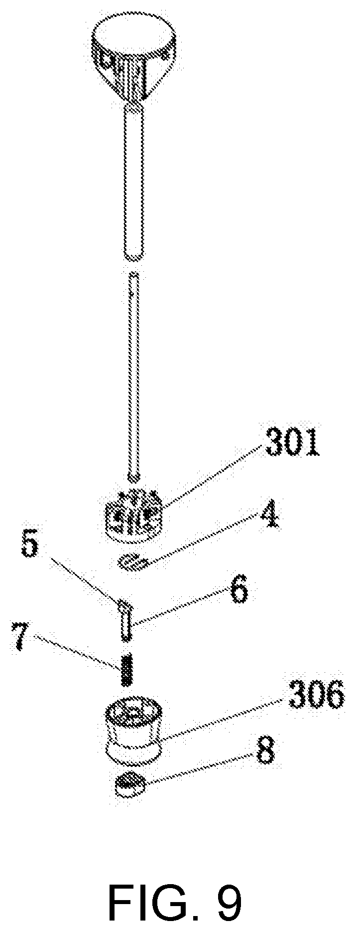
[0019] FIG. 9 is an expanded view of FIG. 7;
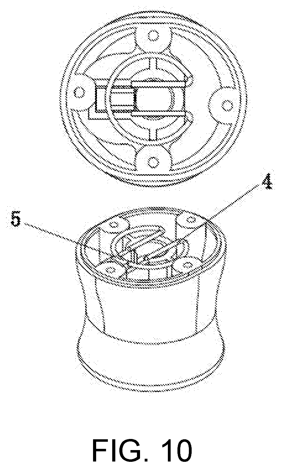
[0020] FIG. 10 is a schematic structural diagram of a lower lock plate assembly in the embodiment 2;
[0021] FIG. 11 is a schematic structural diagram when a central lock in the embodiment 2 is installed on a folding tent;
[0022] FIG. 12 is a schematic diagram of an entire structure of a central lock in an embodiment 3;
[0023] FIG. 13 is a schematic structural diagram when a lock plate in FIG. 12 is detached;
[0024] FIG. 14 is an expanded view of FIG. 12;
[0025] FIG. 15 is a schematic structural diagram of a lower lock plate assembly in the embodiment 3;
[0026] FIG. 16 is a schematic structural diagram when a central lock in the embodiment 3 is installed on a folding tent;
[0027] FIG. 17 is a schematic diagram of an entire structure of a central lock in an embodiment 4;
[0028] FIG. 18 is a schematic structural diagram when a lock plate in FIG. 17 is detached;
[0029] FIG. 19 is an expanded view of FIG. 17;
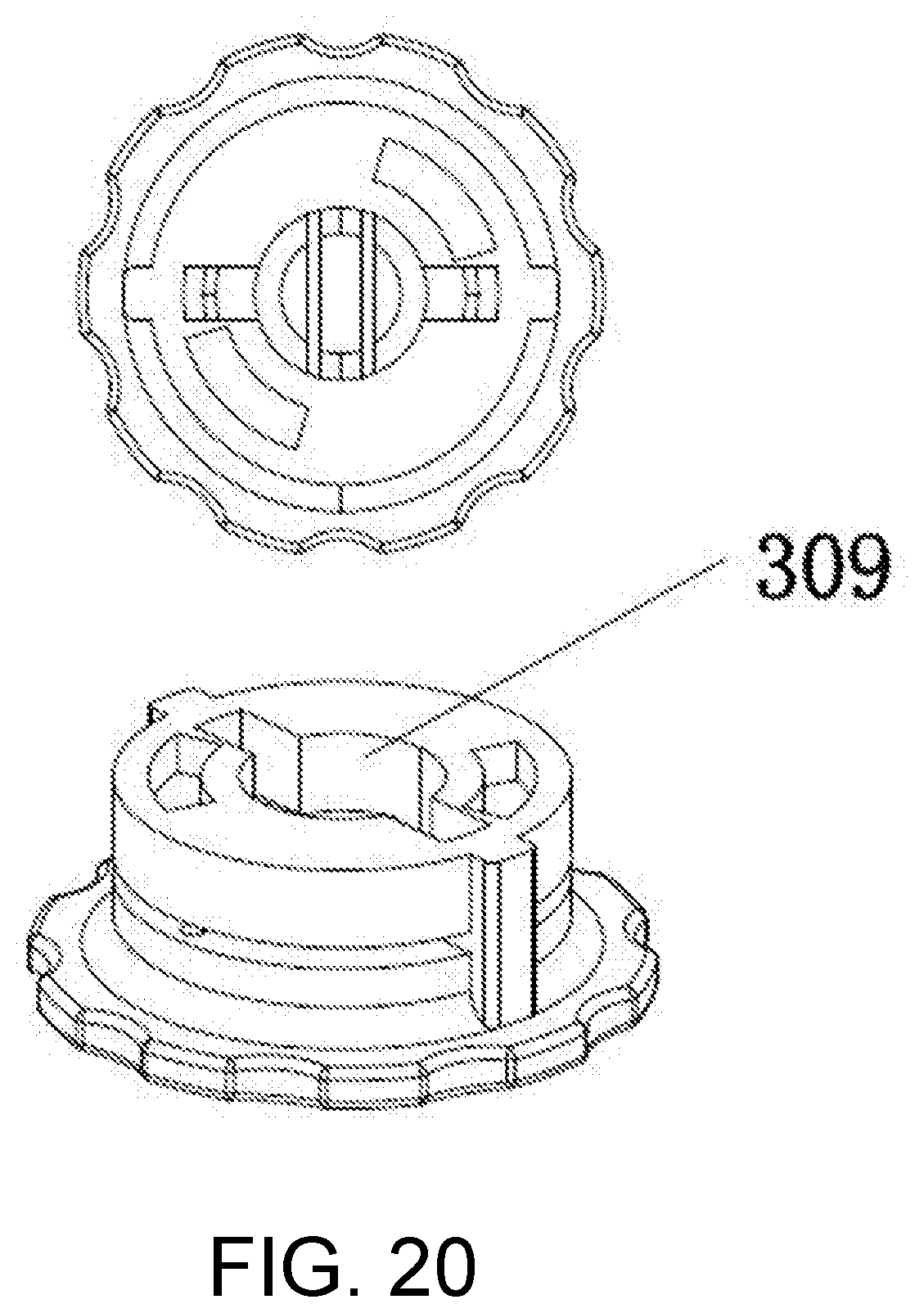
[0030] FIG. 20 is a schematic structural diagram of a lower lock plate assembly in the embodiment 3;
[0031] FIG. 21 is a section view of FIG. 17;
[0032] FIG. 22 is a section view of FIG. 21 taken along line A-A; and
[0033] FIG. 23 is a schematic structural diagram when a central lock in the embodiment 3 is installed on a folding tent.
[0034] In the figures, 1--central lock rod, 101--locking groove, 102--clamping and locking portion, 2--upper lock plate, 3--lower lock plate assembly, 301--upper plate, 302--intermediate plate, 303--lower plate, 304--guiding column, 305--guiding trough, 306--central base, 307--rotary base, 308--central shaft, 309--center hole, 310--outer annular installation groove, 311--outer limit block, 312--inner limit block, 4--elastic locking member, 401--arc-shaped portion, 402--locking rod, 5--unlocking block, 6--unlocking column, 7--compression spring, 8--button cover, 9--inclined conical surface block, 10--columnar unlocking block, 11--pull ring, 12--pull ring fixing block, and 13--arc-shaped gap.
DESCRIPTION OF THE EMBODIMENTS
[0035] The present invention is further described in detail below with reference to the accompanying drawings of the specification, and specific embodiments are provided.
[0036] A central lock for a folding tent in the present invention includes a central lock rod, an upper lock plate fixedly disposed at one end of the central lock rod, and a lower lock plate assembly detachably connected to the other end of the central lock rod. An elastic locking member and an unlocking mechanism used to control the elastic locking member to be locked are disposed in the lower lock plate assembly. The upper lock plate is hingedly connected to a long bone of the folding tent, and the lower lock plate assembly is hingedly connected to a short bone of the folding tent. As shown in FIG. 1, the elastic locking member in the present invention includes an arc-shaped portion provided integrally and two horizontal locking rods extending inwards from a gap of the arc-shaped portion, and a lower end portion of the central lock rod is provided with a locking groove used in cooperation with the locking rods and a clamping and locking portion located at a lower end of the locking groove.
Embodiment 1
[0037] As shown in FIG. 2 to FIG. 6, the lower lock plate assembly in this embodiment includes an upper plate, an intermediate plate, and a lower plate. The upper plate is hingedly connected to a short tent bone, and the upper plate is fixedly connected to the intermediate plate by a screw. A space used to place the elastic locking member is disposed between the intermediate plate and the upper plate, the lower plate is sleeved on a lower end of the intermediate plate, guiding columns are symmetrically disposed on an outer wall of the lower end of the intermediate plate, guiding troughs are provided at locations, corresponding to the guiding columns, of an inner wall of the lower plate, and the guiding columns and the guiding troughs are cooperatively used, so that the intermediate plate and the upper plate slide up and down. The unlocking mechanism includes an unlocking block and an unlocking column fixedly disposed at a lower end of the unlocking block, the unlocking column extends through the intermediate plate to the lower plate and is then fixed by a screw, the unlocking block is in a trapezoid shape with a wider upper width and a narrower lower width. In a locked state, a narrow portion of the lower end of the unlocking block is clamped at the gap of the elastic locking member.
[0038] When unlocking is performed, the intermediate plate is held in hand and pushed upwards, and moves upwards under an action of the guiding columns and the guiding troughs, so that the elastic locking member installed between the intermediate plate and the upper plate is driven to move upwards along the unlocking block. During the upward movement, a distance between the two locking rods is gradually extended by the unlocking block, so that the locking rods are detached from the locking groove, and the central lock rod is detached from the elastic locking member, thereby implementing unlocking, that is, folding the tent.
Embodiment 2
[0039] As shown in FIG. 7 to FIG. 11, in this embodiment, the lower lock plate assembly includes an upper plate and a central base. The upper plate and the central base are fixedly connected by a screw. A space used to place the elastic locking member is provided between the upper plate and an upper portion of the central base. The unlocking mechanism extends through the central base to lock the elastic locking member, and includes an unlocking block, an unlocking column fixedly disposed at a lower end of the unlocking block, a compression spring sleeved on the unlocking column, a button cover and an inclined conical surface block. The bottom cover is clamped on a bottom portion of the central base, and the unlocking column is fixed on the button cover after extending through the central base. A cross section of the unlocking block is a triangle and a surface of an end of the unlocking block is arc-shaped. An intermediate portion of the arc-shaped portion of the elastic locking member abuts on an upper end of an arc-shaped surface of the unlocking block. The inclined conical surface block is correspondingly disposed at the gap of the elastic locking member. A width of an end, of the inclined conical surface block, close to the gap of the locking member is smaller, a width of an end far away from the gap of the locking member is larger, and the inclined conical surface block is disposed on a bottom surface of the upper plate.
[0040] When the central lock disposed for the structure is unlocked, the button cover needs to be first pressed to enable the button cover to move upwards, so as to drive the unlocking columns and the unlocking block to move upwards. During the upward movement, the unlocking block gradually pushes the elastic locking member to go away from the unlocking block and moves horizontally. During the horizontal movement of the elastic locking member, the gap of the elastic locking member is gradually extended by the inclined conical surface block, so that the locking rods are detached from the locking groove, and the central lock rod is detached from the elastic locking member, thereby implementing unlocking, that is, folding the tent. After unlocking is performed, the button cover is loosened, and the unlocking block is reset under an action of the compression spring.
Embodiment 3
[0041] As shown in FIG. 12 to FIG. 15, a structure in this embodiment is basically the same as the structure in the embodiment 2, and a difference lies in a specific structure of the unlocking mechanism. The unlocking mechanism includes a columnar unlocking block, an unlocking column disposed at a lower portion of the columnar unlocking block, a compression spring, a pull ring, a pull ring fixing block, and an inclined conical surface block. The pull ring fixing block is fixedly disposed at a bottom portion of the central base, the compression spring is sleeved on the unlocking column, the pull ring is disposed at an end portion of the unlocking column after the unlocking column extends through the pull ring fixing block, a side surface of the columnar unlocking block is provided with an arc-shaped gap, an intermediate portion of the arc-shaped portion of the elastic locking member abuts on a lower end of the arc-shaped gap, and the inclined conical surface block is correspondingly disposed at the gap of the elastic locking member. Specifically, the inclined conical surface block is disposed in the central base.
[0042] When unlocking is performed, the pull ring is pulled down, the unlocking block moves downwards. When the unlocking block moves downwards, the unlocking block pushes the elastic locking member to horizontally move. During the horizontal movement of the elastic locking member, the gap of the elastic locking member is gradually extended by the inclined conical surface block, so that the locking rods are detached from the locking groove, and the central lock rod is detached from the elastic locking member, thereby implementing unlocking, that is, folding the tent. After unlocking is performed, the button cover is loosened, and the unlocking block is reset under an action of the compression spring.
Embodiment 4
[0043] As shown in FIG. 17 to FIG. 23, the lower lock plate assembly in this embodiment includes an upper plate and a rotary base. A central shaft of a hollow structure is disposed on a lower bottom surface of the upper plate, and a center hole through which the central shaft extends is provided on the rotary base. Two outer annular installation grooves that are spaced apart are formed on an outer wall of the rotary base, and two inner annular installation grooves are formed at locations, corresponding to the two outer annular installation grooves, on an outer wall of the central shaft. Outer limit blocks are disposed between the two outer annular installation grooves, and inner limit blocks are disposed between the two inner annular installation grooves. After the elastic locking member enters from the outer annular installation grooves, outer sides of the gap of the elastic locking member respectively abut on the two outer limit blocks, and the two locking rods respectively abut on the two inner limit blocks. A width between the two locking rods is not less than a width between the inner limit blocks.
[0044] When unlocking is performed, the rotary base is screwed, an end of the gap of the elastic locking member is located on a side of a movement direction of the outer limit blocks, and the outer limit blocks squeeze and exert force on the end of the gap of the elastic locking member, to drive the locking rod on the side to tilt. In addition, the locking rod on the other side also tilts under an action of the outer limit block, so that a distance between the two locking rods is increased and the two locking rods are detached from the locking groove, and the central lock rod is detached from the elastic locking member, thereby implementing unlocking.
* * * * *
D00000
D00001
D00002
D00003
D00004
D00005
D00006
D00007
D00008
D00009
D00010
D00011
D00012

D00013

D00014
D00015

D00016

XML
uspto.report is an independent third-party trademark research tool that is not affiliated, endorsed, or sponsored by the United States Patent and Trademark Office (USPTO) or any other governmental organization. The information provided by uspto.report is based on publicly available data at the time of writing and is intended for informational purposes only.
While we strive to provide accurate and up-to-date information, we do not guarantee the accuracy, completeness, reliability, or suitability of the information displayed on this site. The use of this site is at your own risk. Any reliance you place on such information is therefore strictly at your own risk.
All official trademark data, including owner information, should be verified by visiting the official USPTO website at www.uspto.gov. This site is not intended to replace professional legal advice and should not be used as a substitute for consulting with a legal professional who is knowledgeable about trademark law.