Electromagnetic Valve Identification Device And Control Unit Including Same
KONDO; Akihiro ; et al.
U.S. patent application number 16/643807 was filed with the patent office on 2020-07-30 for electromagnetic valve identification device and control unit including same. This patent application is currently assigned to KAWASAKI JUKOGYO KABUSHIKI KAISHA. The applicant listed for this patent is KAWASAKI JUKOGYO KABUSHIKI KAISHA. Invention is credited to Akihiro KONDO, Yuki NAKAYAMA, Ryuji SAKAI.
| Application Number | 20200240115 16/643807 |
| Document ID | 20200240115 / US20200240115 |
| Family ID | 1000004768398 |
| Filed Date | 2020-07-30 |
| Patent Application | download [pdf] |


| United States Patent Application | 20200240115 |
| Kind Code | A1 |
| KONDO; Akihiro ; et al. | July 30, 2020 |
ELECTROMAGNETIC VALVE IDENTIFICATION DEVICE AND CONTROL UNIT INCLUDING SAME
Abstract
An electromagnetic valve identification device configured to realize individual identification of an electromagnetic valve while suppressing an increase in manufacturing cost. The electromagnetic valve identification device is mounted on an industrial machine, such as a construction machine or an industrial vehicle, configured to move a hydraulic actuator to perform work. The electromagnetic valve identification device includes: an inductance measuring circuit configured to supply an alternating current to a solenoid of an electromagnetic valve of a hydraulic device, the hydraulic device being configured to supply pressure oil to the hydraulic actuator to operate the hydraulic actuator; a calculating portion configured to calculate an inductance of the solenoid based on the alternating current supplied to the solenoid by the inductance measuring circuit; and a storage portion configured to store the calculated inductance of the solenoid as individual identification information of the electromagnetic valve.
| Inventors: | KONDO; Akihiro; (Kobe-shi, JP) ; SAKAI; Ryuji; (Kakogawa-shi, JP) ; NAKAYAMA; Yuki; (Amagasaki-shi, JP) | ||||||||||
| Applicant: |
|
||||||||||
|---|---|---|---|---|---|---|---|---|---|---|---|
| Assignee: | KAWASAKI JUKOGYO KABUSHIKI
KAISHA Kobe-shi, Hyogo JP |
||||||||||
| Family ID: | 1000004768398 | ||||||||||
| Appl. No.: | 16/643807 | ||||||||||
| Filed: | August 22, 2018 | ||||||||||
| PCT Filed: | August 22, 2018 | ||||||||||
| PCT NO: | PCT/JP2018/030961 | ||||||||||
| 371 Date: | March 2, 2020 |
| Current U.S. Class: | 1/1 |
| Current CPC Class: | E02F 9/2296 20130101; F15B 2211/6316 20130101; E02F 9/2004 20130101; E02F 9/2221 20130101; F15B 2211/6651 20130101; E02F 9/2285 20130101; E02F 9/2246 20130101 |
| International Class: | E02F 9/22 20060101 E02F009/22 |
Foreign Application Data
| Date | Code | Application Number |
|---|---|---|
| Aug 31, 2017 | JP | 2017-167464 |
Claims
1. An electromagnetic valve identification device mounted on an industrial machine, such as a construction machine or an industrial vehicle, configured to move a hydraulic actuator to perform work, the electromagnetic valve identification device comprising: an inductance measuring circuit configured to supply an alternating current to a solenoid of an electromagnetic valve of a hydraulic device, the hydraulic device being configured to supply pressure oil to the hydraulic actuator to operate the hydraulic actuator; a calculating portion configured to calculate an inductance of the solenoid based on the alternating current supplied to the solenoid by the inductance measuring circuit; and a storage portion configured to store the calculated inductance of the solenoid as individual identification information of the electromagnetic valve.
2. The electromagnetic valve identification device according to claim 1, further comprising a replacement determining portion configured to determine whether or not the electromagnetic valve has been replaced, based on a determination criterion in which whether or not the electromagnetic valve has been replaced is determined by using the inductance calculated by the calculating portion.
3. The electromagnetic valve identification device according to claim 2, wherein: the determination criterion includes whether or not a reference inductance of the solenoid and an actually measured inductance of the solenoid are different from each other, the reference inductance being calculated by the calculating portion and stored in the storage portion in advance, the actually measured inductance being calculated by the calculating portion; and when the actually measured inductance is different from the reference inductance, the replacement determining portion determines that the electromagnetic valve has been replaced.
4. The electromagnetic valve identification device according to claim 3, wherein: when a predetermined reference value setting condition is satisfied, the calculating portion calculates the reference inductance of the solenoid; and the storage portion stores the reference inductance calculated by the calculating portion.
5. The electromagnetic valve identification device according to claim 2, wherein: the determination criterion includes whether or not the actually measured inductance calculated by the calculating portion falls within a predetermined allowable range; and when the actually measured inductance falls outside the allowable range, the replacement determining portion determines that the electromagnetic valve has been replaced.
6. The electromagnetic valve identification device according to claim 2, further comprising a resistance measuring portion configured to supply a direct current to the solenoid and measure a resistance value of the solenoid, wherein: the determination criterion includes whether or not a reference resistance value of the solenoid and an actually measured resistance value of the solenoid are different from each other, the reference resistance value being measured by the resistance measuring portion in advance, the actually measured resistance value being measured by the resistance measuring portion; and the replacement determining portion compares the actually measured resistance value with the reference resistance value and determines whether or not the electromagnetic valve has been replaced.
7. An electromagnetic valve identification device mounted on an industrial machine, such as a construction machine or an industrial vehicle, configured to move a hydraulic actuator to perform work, the electromagnetic valve identification device comprising: a resistance measuring portion configured to supply a direct current to a solenoid of an electromagnetic valve of a hydraulic device and measure a resistance value of the solenoid, the hydraulic device being configured to supply pressure oil to the hydraulic actuator to operate the hydraulic actuator; and a replacement determining portion configured to determine whether or not the electromagnetic valve has been replaced, based on a determination criterion in which whether or not the electromagnetic valve has been replaced is determined by using the resistance value measured by the resistance measuring portion.
8. The electromagnetic valve identification device according to claim 7, wherein the determination criterion includes whether or not a reference resistance value of the solenoid and an actually measured resistance value of the solenoid are different from each other, the reference resistance value being measured by the resistance measuring portion in advance, the actually measured resistance value being measured by the resistance measuring portion.
9. A control unit comprising: the electromagnetic valve identification device according to claim 2; and a control device mounted on the industrial vehicle and configured to supply a current to the solenoid of the electromagnetic valve to control an operation of the electromagnetic valve, wherein the control device is configured to restrict the operation of the electromagnetic valve when the replacement determining portion determines that the electromagnetic valve has been replaced.
Description
TECHNICAL FIELD
[0001] The present invention relates to an electromagnetic valve identification device configured to perform individual identification of an electromagnetic valve mounted on an industrial machine, such as a construction machine or an industrial vehicle, and a control unit including the electromagnetic valve identification device.
BACKGROUND ART
[0002] Construction machines (such as hydraulic excavators and wheel loaders) and travelable industrial vehicles (such as forklifts) can perform various types of work by moving attachments (such as buckets and forks). According to the construction machines and industrial vehicles having such function, the attachments are moved by operating hydraulic actuators (such as hydraulic cylinders and hydraulic motors). The hydraulic actuators are driven by being supplied with operating oil. The industrial vehicles include hydraulic devices configured to supply the operating oil to the hydraulic actuators. In order to change a tilting angle of a hydraulic pump and move a spool of a flow control valve, the hydraulic device includes a plurality of electromagnetic valves.
[0003] As with other devices, the electromagnetic valve may be required to be replaced due to breakdown or the like and is actually replaced once in a while. Typically, the electromagnetic valve of the hydraulic device is replaced with a proper hydraulic device, and with this, the function of the hydraulic device is secured. Therefore, when replacing the electromagnetic valve, it is preferable to use a proper product having the same function and quality as the electromagnetic valve equipped in a construction machine or industrial vehicle when the construction machine or industrial vehicle is assembled and manufactured. However, actually, electromagnetic valves that are improper products having low quality are used as replacement parts in some cases. In such cases, the hydraulic device cannot exert a desired function, and in the worst case, the hydraulic device and various devices of the industrial vehicle may be damaged. In order to prevent the use of the improper product at the time of replacement, for example, devices of PTLs 1 and 2 are known.
[0004] According to an identification device of PTL 1, IC chips are attached to replaceable parts. Then, the identification device detects information stored in the IC chips and determines whether the replaceable parts are genuine products (proper products) or counterfeit products (improper products). Further, according to an improper part use prevention system of PTL 2, part IDs are attached to replaceable parts, and the part IDs are input through an input unit. The input part IDs are transmitted to a data server through a wireless communication network, and whether or not the input part IDs are part IDs of unused parts is determined. Thus, the improper products are prevented from being used.
CITATION LIST
Patent Literature
[0005] PTL 1: Japanese Patent No. 4399524
[0006] PTL 2: Japanese Laid-Open Patent Application Publication No. 2016-98528
SUMMARY OF INVENTION
Technical Problem
[0007] According to the identification device of PTL 1, the individual identification of the replaceable parts is performed based on the information stored in the IC chips, and therefore, the IC chips have to be attached to the respective parts. In addition, in order to perform the individual identification, sensors configured to detect the information of the IC chips need to be arranged at various places. Thus, the number of parts increases, and this increases the manufacturing cost.
[0008] According to the improper part use prevention system of PTL 2, the individual identification of the replaceable parts is performed by attaching the part IDs to the respective replaceable parts. The individual identification needs to be performed by transmitting the part IDs to the data server. Therefore, a wireless communication device and the data server are necessary, and this increases the manufacturing cost.
[0009] An object of the present invention is to provide an electromagnetic valve identification device configured to perform individual identification of an electromagnetic valve while suppressing a manufacturing cost.
Solution to Problem
[0010] An electromagnetic valve identification device according to the present invention is an electromagnetic valve identification device mounted on an industrial machine, such as a construction machine or an industrial vehicle, configured to move a hydraulic actuator to perform work. The electromagnetic valve identification device includes: an inductance measuring circuit configured to supply an alternating current to a solenoid of an electromagnetic valve of a hydraulic device, the hydraulic device being configured to supply pressure oil to the hydraulic actuator to operate the hydraulic actuator; a calculating portion configured to calculate an inductance of the solenoid based on the alternating current supplied to the solenoid by the inductance measuring circuit; and a storage portion configured to store the calculated inductance of the solenoid as individual identification information of the electromagnetic valve.
[0011] According to the present invention, the inductance of the solenoid of the electromagnetic valve is stored as the individual identification information. Regarding the inductances of the solenoids, the inductance of each solenoid has a specific value. However, typically, even when solenoids are the same in winding number and wire diameter as one another, the inductances of the respective solenoids have different numerical values, i.e., the inductances of the respective solenoids vary. Therefore, the inductance of the solenoid of the electromagnetic valve can be used as the individual identification information of the electromagnetic valve. To be specific, the individual identification of the electromagnetic valve and a part including the electromagnetic valve can be performed by mounting such electromagnetic valve identification device on the industrial vehicle. Therefore, it is unnecessary to attach IC chips to electromagnetic valves and parts including the electromagnetic valves mounted on industrial vehicles or attach IDs to electromagnetic valves and parts including the electromagnetic valves mounted on industrial vehicles to manage the electromagnetic valves and the parts, in order to perform the individual identification of the electromagnetic valves. Thus, the manufacturing cost can be suppressed.
[0012] In the above invention, the electromagnetic valve identification device may further include a replacement determining portion configured to determine whether or not the electromagnetic valve has been replaced, based on a determination criterion in which whether or not the electromagnetic valve has been replaced is determined by using the inductance calculated by the calculating portion.
[0013] According to the above configuration, whether or not the electromagnetic valve has been replaced can be determined by using the inductance of the solenoid, i.e., the individual identification information. Therefore, whether or not the electromagnetic valve has been replaced can be determined by a simple configuration without attaching IC chips to electromagnetic valves and parts including the electromagnetic valves mounted on industrial vehicles or attaching IDs to electromagnetic valves and parts including the electromagnetic valves mounted on industrial vehicles to manage the electromagnetic valves and the parts.
[0014] In the above invention, the determination criterion may include whether or not a reference inductance of the solenoid and an actually measured inductance of the solenoid are different from each other, the reference inductance being calculated by the calculating portion and stored in the storage portion in advance, the actually measured inductance being calculated by the calculating portion, and when the actually measured inductance is different from the reference inductance, the replacement determining portion may determine that the electromagnetic valve has been replaced.
[0015] According to the above configuration, whether or not the electromagnetic valve having the same inductance is being continuously mounted can be determined, i.e., whether or not the same electromagnetic valve is being continuously mounted can be determined. When the same electromagnetic valve is not being continuously mounted, it can be determined that the electromagnetic valve has been replaced at a certain time point. Therefore, whether or not the replacement work has been performed can be surely determined.
[0016] In the above invention, when a predetermined reference value setting condition is satisfied, the calculating portion may calculate the reference inductance of the solenoid, and the storage portion may store the reference inductance calculated by the calculating portion.
[0017] According to the above configuration, when the reference value setting condition is satisfied after the electromagnetic valve has been replaced, the inductance of the replaced electromagnetic valve can be newly stored as the reference inductance. On the other hand, when the reference value setting condition is not satisfied, the reference inductance cannot be reset. Therefore, it is possible to prevent a case where the reference inductance is freely changed, and the electromagnetic valve is made to look as if it has not been replaced.
[0018] In the above invention, the determination criterion may include whether or not the actually measured inductance calculated by the calculating portion falls within a predetermined allowable range, and when the actually measured inductance falls outside the allowable value, the replacement determining portion may determine that the electromagnetic valve has been replaced.
[0019] According to the above configuration, whether or not the electromagnetic valve has been replaced can be determined based on whether or not the inductance of the replaced electromagnetic valve, i.e., the actually measured inductance falls outside the allowable range. Therefore, it is possible to prevent a case where an electromagnetic valve having an inductance that falls outside the allowable range is adopted as a replacement part. It should be noted that the allowable range is, for example, a range of manufacturing error (tolerance) of electromagnetic valves (for example, electromagnetic valves as proper products) that are not the same as one another but can exert substantially the same function. With this, the replacement of the electromagnetic valve having the inductance that falls outside the allowable range can be found, i.e., the replacement of the electromagnetic valve that is an improper product, such as a counterfeit product, can be found.
[0020] In the above invention, the electromagnetic valve identification device may further include a resistance measuring portion configured to supply a direct current to the solenoid and measure a resistance value of the solenoid. The determination criterion may include whether or not a reference resistance value of the solenoid and an actually measured resistance value of the solenoid are different from each other, the reference resistance value being measured by the resistance measuring portion in advance, the actually measured resistance value being measured by the resistance measuring portion, and the replacement determining portion may compare the actually measured resistance value with the reference resistance value and determine whether or not the electromagnetic valve has been replaced.
[0021] According to the above configuration, whether or not the electromagnetic valve has been replaced can be determined based on the resistance value of the solenoid of the electromagnetic valve. When solenoids are the same in winding number and wire diameter as one another, the resistance values of such solenoids vary less than the inductances of the solenoids. Therefore, the type and the like of the electromagnetic valve can be specified by comparing the resistance value of the solenoid of the electromagnetic valve with the reference resistance value. On this account, by using the resistance value of the solenoid of the electromagnetic valve in the individual identification together with the inductance of the solenoid of the electromagnetic valve, the individual identification of the electromagnetic valves and the parts including the electromagnetic valves can be performed more accurately.
[0022] An electromagnetic valve identification device according to the present invention is an electromagnetic valve identification device mounted on an industrial machine, such as a construction machine or an industrial vehicle, configured to move a hydraulic actuator to perform work. The electromagnetic valve identification device includes: a resistance measuring portion configured to supply a direct current to a solenoid of an electromagnetic valve of a hydraulic device and measure a resistance value of the solenoid, the hydraulic device being configured to supply pressure oil to the hydraulic actuator to operate the hydraulic actuator; and a replacement determining portion configured to determine whether or not the electromagnetic valve has been replaced, based on a determination criterion in which whether or not the electromagnetic valve has been replaced is determined by using the resistance value measured by the resistance measuring portion.
[0023] According to the present invention, whether or not the electromagnetic valve has been replaced can be determined by using the resistance of the solenoid, i.e., the individual identification information. Therefore, whether or not the electromagnetic valve has been replaced can be determined by a simple configuration without attaching IC chips to electromagnetic valves and parts including the electromagnetic valves mounted on industrial vehicles or attaching IDs to electromagnetic valves and parts including the electromagnetic valves mounted on industrial vehicles to manage the electromagnetic valves and the parts. In addition, typically, the above effects can be obtained only by changing software or control logic without changing the hardware configuration of a conventional control device. Further, the resistance value of the solenoid can be detected by a smaller number of parts than the inductance of the solenoid. Therefore, the determination based on the resistance is lower in cost than the determination based on the inductance.
[0024] In the above invention, the determination criterion may include whether or not a reference resistance value of the solenoid and an actually measured resistance value of the solenoid are different from each other, the reference resistance value being measured by the resistance measuring portion in advance, the actually measured resistance value being measured by the resistance measuring portion.
[0025] According to the above configuration, whether or not the electromagnetic valve has been replaced can be determined by comparing the resistance values.
[0026] A control unit according to the present invention includes: the above-described electromagnetic valve identification device; and a control device mounted on the industrial vehicle and configured to supply a current to the solenoid of the electromagnetic valve to control an operation of the electromagnetic valve. The control device is configured to restrict the operation of the electromagnetic valve when the replacement determining portion determines that the electromagnetic valve has been replaced.
[0027] According to the above configuration, it is possible to prevent the use of the hydraulic device whose function is made low since, for example, the replaced electromagnetic valve is an improper product, or the electromagnetic valve is replaced through an improper method.
Advantageous Effects of Invention
[0028] According to the present invention, the individual identification of the electromagnetic valve can be performed while suppressing an increase in the manufacturing cost.
BRIEF DESCRIPTION OF DRAWINGS
[0029] FIG. 1 is a hydraulic circuit diagram showing the configuration of a hydraulic device including a control unit according to Embodiment 1 of the present invention.
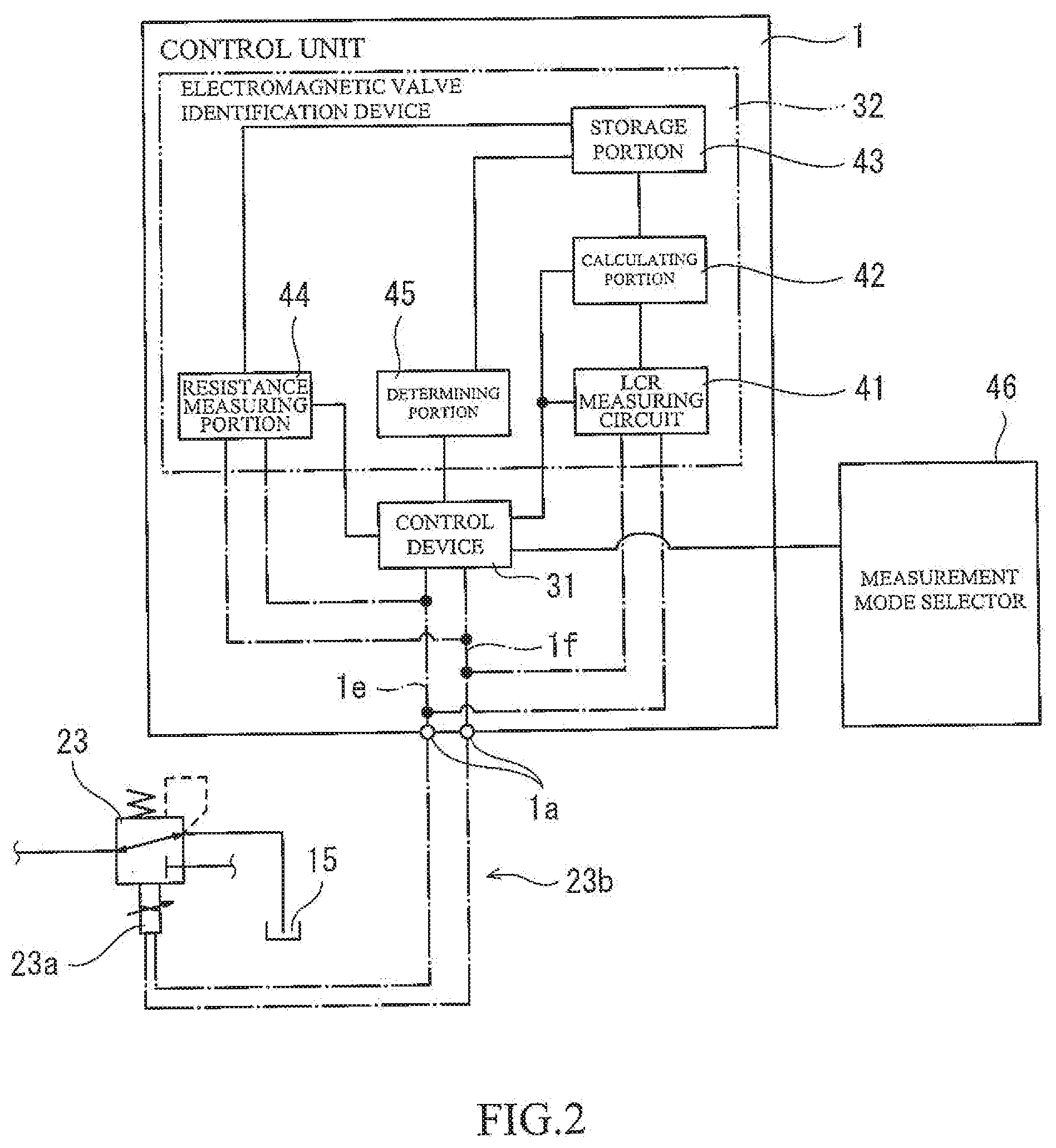
[0030] FIG. 2 is a block diagram showing functional blocks of the control unit of FIG. 1.
[0031] FIG. 3 is an electric circuit diagram showing the configuration of an LCR measuring circuit included in the control unit of FIG. 2.
[0032] FIG. 4 is a flow chart showing the procedure of individual identification processing executed by the control unit shown in FIG. 2.
[0033] FIG. 5 is a flow chart showing the procedure of reference value measurement processing executed in a reference value measurement mode of FIG. 4.
[0034] FIG. 6 is a flow chart showing the procedure of actually measured value measurement processing executed in an actually measured value measurement mode of FIG. 4.
[0035] FIG. 7 is a block diagram showing functional blocks of the control unit of Embodiment 2.
DESCRIPTION OF EMBODIMENTS
[0036] Hereinafter, control units 1 and 1A according to Embodiments 1 and 2 of the present invention will be described with reference to the drawings. It should be noted that directions stated in the following description are used for convenience sake, and directions and the like of components of the present invention are not limited. Each of the control units 1 and 1A described below is just one embodiment of the present invention. Therefore, the present invention is not limited to the embodiments, and additions, deletions, and modifications may be made within the scope of the present invention.
[0037] Construction Machine and Industrial Vehicle
[0038] Construction machines and industrial vehicles as examples of industrial machines perform various types of work by moving various attachments. Examples of the construction machines include hydraulic excavators, wheel loaders, cranes, skid steer loaders, and aerial work platform vehicles, and examples of the industrial vehicles include forklifts. These construction machines and industrial vehicles can perform work, such as excavating work and carrying work. For example, a hydraulic excavator includes a bucket and performs excavation by the bucket. Further, the hydraulic excavator includes a travelable vehicle body and can change an excavation position and carry, for example, excavated sand by making the vehicle body travel. In the hydraulic excavator configured as above, the bucket is attached to the vehicle body through a boom and an arm. The hydraulic excavator performs excavating work by making the bucket, the boom, and the arm swing in front, rear, upper, and lower directions. Further, the hydraulic excavator makes the bucket, the boom, and the arm swing by hydraulic cylinders.
[0039] The hydraulic cylinder that is one example of a hydraulic actuator operates by being supplied with operating oil that is pressure oil. To be specific, the hydraulic cylinder expands or contracts in accordance with a flow direction of the operating oil supplied thereto and operates at a speed corresponding to a flow rate of the operating oil supplied thereto. As above, the hydraulic cylinder is driven by the operating oil supplied thereto, and the hydraulic excavator includes a hydraulic driving apparatus 2 configured to supply the operating oil to the hydraulic cylinder.
[0040] Hydraulic Device
[0041] As shown in FIG. 1, the hydraulic driving apparatus 2 mainly includes a hydraulic pump device 11, a plurality of flow rate control devices 12, and a bleed-off valve 13. It should be noted that FIG. 1 shows only one flow rate control device 12 located at a most upstream side among the plurality of flow rate control devices 12, and does not show the other flow rate control devices 12. The hydraulic pump device 11 is configured to discharge the operating oil to supply the operating oil to the hydraulic actuator. The hydraulic pump device 11 includes a hydraulic pump 21, a regulator 22, and an electromagnetic proportional valve 23. The hydraulic pump 21 is coupled to a driving source, such as an engine (not shown), and is rotated by the driving source. By this rotation, the hydraulic pump 21 sucks the operating oil from a tank 15 and discharges the operating oil to a main passage 16. The hydraulic pump 21 is a variable displacement swash plate pump and includes a swash plate 21a. A tilting angle of the swash plate 21a is changeable, and a discharge volume of the hydraulic pump 21 changes by changing the tilting angle. The regulator 22 is attached to the swash plate 21a having such function. The electromagnetic proportional valve 23 is attached to the regulator 22. The regulator 22 is formed integrally with a casing of the hydraulic pump 21.
[0042] The regulator 22 is a mechanism configured to change the tilting angle of the swash plate 21a and includes a servo piston (not shown). The servo piston is coupled to the swash plate 21a and can reciprocate along an axis thereof. The servo piston configured as above can change the tilting angle of the swash plate 21a by changing a position thereof. Further, the servo piston changes the position thereof in accordance with pilot pressure p input thereto. The electromagnetic proportional valve 23 configured to apply the pilot pressure p to the servo piston is connected to the regulator 22.
[0043] The electromagnetic proportional valve 23 is a so-called direct proportion type electromagnetic valve and outputs pilot oil having pressure corresponding to a current (discharge volume command current) input thereto. More specifically, the electromagnetic proportional valve 23 is connected to the regulator 22, the tank 15, and a pilot pump (not shown). The electromagnetic proportional valve 23 includes a solenoid 23a. In accordance with a current supplied to the solenoid 23a, the electromagnetic proportional valve 23 adjusts a connection status between the regulator 22 and the tank 15, an opening degree therebetween, a connection status between the regulator 22 and the pilot pump, and an opening degree therebetween. To be specific, when a current is not supplied to the solenoid 23a of the electromagnetic proportional valve 23, the regulator 22 and the tank 15 are connected to each other. On the other hand, when a current is supplied to the solenoid 23a, communication between the regulator 22 and the tank 15 is closed, and the regulator 22 and the pilot pump are connected to each other. Further, in accordance with a current supplied to the solenoid 23a, the opening degree between the regulator 22 and the pilot pump increases, and the opening degree between the regulator 22 and the tank decreases.
[0044] The electromagnetic proportional valve 23 configured as above outputs to the regulator 22 the pilot pressure p corresponding to the current supplied to the solenoid 23a. With this, the servo piston of the regulator 22 moves to a position corresponding to the discharge volume command current, and the swash plate 21a tilts at the tilting angle corresponding to the position of the servo piston. Therefore, the operating oil is discharged from the hydraulic pump 21 to the main passage 16 at the discharge flow rate corresponding to the discharge volume command current. The plurality of flow rate control devices 12 are connected to the main passage 16 in parallel. In the present embodiment, three flow rate control devices 12 are connected to the main passage 16 in parallel.
[0045] The three flow rate control devices 12 are provided so as to correspond to respective hydraulic actuators. The hydraulic excavator of the present embodiment includes three cylinders, for convenience of explanation. To be specific, the hydraulic excavator includes a boom cylinder configured to move the boom, an arm cylinder configured to move the arm, and a bucket cylinder configured to move the bucket. The three flow rate control devices 12 correspond to the respective hydraulic cylinders. Each flow rate control device 12 controls the flow direction and flow rate of the operating oil flowing through the corresponding hydraulic cylinder. These three flow rate control devices 12 are basically the same in configuration as one another except that targets to which the three flow rate control devices 12 correspond are different from one another. Therefore, the following will just describe the configuration of a boom flow rate control device 12 corresponding to the boom cylinder located at the most upstream side as shown in FIG. 1, detailed explanations of the configurations of the other two flow rate control devices that are an arm flow rate control device and a bucket flow rate control device are omitted since the explanation of the configuration of the boom flow rate control device 12 is referable.
[0046] The flow rate control device 12 includes a flow control valve 25 and a pair of electromagnetic proportional valves 26L and 26R. The flow control valve 25 controls the flow direction and flow rate of the operating oil supplied to the boom cylinder. More specifically, the flow control valve 25 is connected to the main passage 16 and also connected to the tank 15 through a tank passage 17. The flow control valve 25 is connected to the boom cylinder through a rod-side passage 18 and a head-side passage 19. The rod-side passage 18 is connected to a rod-side port of the boom cylinder, and the head-side passage 19 is connected to a head-side port of the boom cylinder. Therefore, the boom cylinder contracts by supplying the operating oil to the rod-side passage 18 and discharging the operating oil from the head-side passage 19. In contrast, the boom cylinder expands by discharging the operating oil from the rod-side passage 18 and supplying the operating oil to the head-side passage 19.
[0047] The flow control valve 25 includes a spool 25a and changes connection statuses of the four passages 16 to 19 in accordance with the position of the spool 25a. To be specific, when the spool 25a is located at a neutral position M, all the four passages 16 to 19 are blocked. When the spool 25a moves to a first offset position L, the rod-side passage 18 is connected to the main passage 16, and the head-side passage 19 is connected to the tank passage 17. When the spool 25a moves to a second offset position R, the rod-side passage 18 is connected to the tank passage 17, and the head-side passage 19 is connected to the main passage 16. Further, the opening degrees of the four passages 16 to 19 change in accordance with the position of the spool 25a. With this, the flow control valve 25 can supply the operating oil to the boom cylinder at the flow rate corresponding to the position of the spool 25a. To be specific, the boom cylinder can be moved at a speed corresponding to the position of the spool 25a. Pilot pressure pL and pilot pressure pR are applied to the spool 25a so as to act against each other, and the spool 25a having such function moves to a position corresponding to differential pressure between the pilot pressure pL and the pilot pressure pR. In order to apply the pilot pressure pL and the pilot pressure pR to the spool 25a, the pair of electromagnetic proportional valves 26L and 26R are provided at the flow control valve 25.
[0048] The pair of electromagnetic proportional valves 26L and 26R are direct proportion type electromagnetic proportional valves that are similar in configuration to each other. The electromagnetic proportional valve 26L outputs the pilot pressure pL corresponding to an operating command current input thereto, and the electromagnetic proportional valve 26R outputs the pilot pressure pR corresponding to an operating command current input thereto. More specifically, the electromagnetic proportional valves 26L and 26R are connected to the flow control valve 25, the tank 15, and the pilot pump (not shown). Each of the electromagnetic proportional valves 26L and 26R includes a solenoid 26a and adjusts a connection status between the tank 15 and the flow control valve 25, a connecting status between the pilot pump and the flow control valve 25, an opening degree between the tank 15 and the flow control valve 25, and an opening degree between the pilot pump and the flow control valve 25 in accordance with a current supplied to the solenoid 26a. To be specific, the electromagnetic proportional valve 26L has the same function as the electromagnetic proportional valve 23 of the hydraulic pump device 11 and outputs the pilot pressure pL corresponding to the operating command current supplied thereto, and the electromagnetic proportional valve 26R has the same function as the electromagnetic proportional valve 23 of the hydraulic pump device 11 and outputs the pilot pressure pR corresponding to the operating command current supplied thereto. With this, the spool 25a of the flow control valve 25 moves to a position corresponding to the operating command current, and the operating oil is supplied to the boom cylinder in the flow direction corresponding to the operating command current at the flow rate corresponding to the operating command current. To be specific, the flow control valve 25 can make the boom cylinder expand and contract in a direction corresponding to the operating command current at a speed corresponding to the operating command current. In order to adjust the flow rate of the operating oil supplied to the hydraulic cylinders including the boom cylinder, the bleed-off valve 13 is connected to the main passage 16.
[0049] The bleed-off valve 13 is an electromagnetic proportional valve. The bleed-off valve 13 has a function of discharging to the tank 15 the operating oil flowing through the main passage 16, i.e., has a function of performing bleed-off. The bleed-off valve 13 having such function includes a solenoid 13a, and a bleed-off command current is input to the solenoid 13a. When the bleed-off command current is input to the solenoid 13a, the bleed-off valve 13 adjusts an opening degree between the main passage 16 and the tank 15 in accordance with the bleed-off command current. With this, the bleed-off of the operating oil can be performed at the flow rate corresponding to the bleed-off command current, and this can adjust the flow rate of the operating oil flowing through the main passage 16. In order to input the bleed-off command current to the bleed-off valve 13 having such function, the control unit 1 is electrically connected to the bleed-off valve 13.
[0050] Control Unit
[0051] The control unit 1 shown in FIG. 2 includes a CPU (Central Processing Unit), a ROM (Read Only Memory), a RAM (Random Access Memory), and the like (all not shown). The ROM stores programs executed by the CPU, various fixed data, and the like. The programs executed by the CPU are stored in various storage mediums, such as flexible disks, CD-ROMs, and memory cards, and are installed to the ROM from such storage mediums. The RAM configured as above temporarily stores data necessary when executing the programs. The control unit 1 is electrically connected to the solenoid 13a of the bleed-off valve 13, the solenoid 23a of the electromagnetic proportional valve 23 of the hydraulic pump device 11, and the solenoids 26a of the pair of electromagnetic proportional valves 26R and 26L. In order to control the operations of the valves 13, 23, 26R, and 26L, the control unit 1 includes a control device 31.
[0052] The control device 31 is connected to an operating device (not shown), and the operating device includes three operating levers respectively corresponding to the boom, the arm, and the bucket. When the operating lever is operated, the operating device outputs to the control device 31 an operation command corresponding to an operation direction and operation amount of the operating lever. Then, the control device 31 supplies a command current to the solenoid 13a, 23a, or 26a in accordance with the operation command input thereto. With this, the corresponding hydraulic cylinder expands or contracts in a direction corresponding to the operation direction of the operating lever at a speed corresponding to the operation amount of the operating lever. The control device 31 moves the hydraulic cylinders by controlling the operations of the valves 13, 23, 26R, and 26L as above.
[0053] The control device 31 selects a normal mode or a restriction mode as an operating mode of the hydraulic driving apparatus 2. In the restriction mode, the function of the hydraulic driving apparatus 2 is restricted (for example, upper limits of the pilot pressures p, pL, and pR which can be output from the proportional valves 23, 26R, and 26L are set low), and therefore, maximum outputs of the hydraulic cylinders are restricted. On the other hand, in the normal mode, the functions of the valves 23, 26R, and 26L are not restricted, and therefore, the hydraulic cylinders can maximally exert their functions (i.e., each hydraulic cylinder can output a maximum output set at the time of designing). These two modes are switched in accordance with the hydraulic pump device 11 mounted on the hydraulic excavator. More specifically, when the hydraulic pump device 11 mounted is not a proper product (i.e., a genuine product) or is not replaced properly, the control device 31 selects the restriction mode. In order to determine whether to switch the operating mode to the restriction mode, the control unit 1 performs individual identification of the hydraulic pump device 11 mounted on the hydraulic excavator (i.e., individual identification of the electromagnetic proportional valve 23 of the hydraulic pump device 11). In order to perform the individual identification of the hydraulic pump device 11 based on the electromagnetic proportional valve 23, the control unit 1 includes an electromagnetic valve identification device 32.
[0054] Electromagnetic Valve Identification Device
[0055] In order to perform the individual identification of the electromagnetic proportional valve 23, the electromagnetic valve identification device 32 measures a resistance value and inductance of the solenoid 23a of the electromagnetic proportional valve 23. Regarding the resistance values of the solenoids 23a, the resistance values of the solenoids of the electromagnetic proportional valves of the same type vary little. On the other hand, regarding the inductances of the solenoids 23a, the inductance of each solenoid 23a has a specific value. However, in many cases, even when the electromagnetic proportional valves are of the same type (i.e., the solenoids are the same in winding number and wire diameter as one another), the inductances of the respective solenoids 23a of the electromagnetic proportional valves have different numerical values due to the shapes, size variations, and the like of magnetic bodies arranged around the electromagnetic proportional valves. To be specific, the solenoids 23a vary. Therefore, the individual identification of the electromagnetic proportional valve 23 can be performed based on the resistance value and the inductance. In order to specify the type of the electromagnetic proportional valve and perform the individual identification of the electromagnetic proportional valve, the electromagnetic valve identification device 32 includes an LCR measuring circuit 41, a calculating portion 42, a storage portion 43, a resistance measuring portion 44, and a determining portion 45. The LCR measuring circuit 41 is one example of an inductance measuring circuit and measures the inductance of the solenoid 23a of the electromagnetic proportional valve 23. The LCR measuring circuit 41 is constituted by a circuit connected to the electromagnetic proportional valve 23 by, for example, a four-terminal method as shown in FIG. 3. A connection method and circuit configuration adopted in the LCR measuring circuit 41 are not limited to those shown in FIG. 3. A known circuit capable of measuring the inductance of the solenoid 23a of the electromagnetic proportional valve 23 may be adopted.
[0056] The LCR measuring circuit 41 and the control device 31 are formed on a single substrate to constitute the control unit 1. It should be noted that the LCR measuring circuit 41 does not necessarily have to be formed on the substrate on which the control device 31 is formed, and the LCR measuring circuit 41, the below-described calculating portion 42, and the below-described storage portion 43 may be configured as a different device (for example, an LCR meter). Further, the control unit 1 including the substrate on which the LCR measuring circuit 41 and the control device 31 are formed includes interfaces 1a to 1d, and the solenoids 13a, 23a, and 26a are electrically connected to the control unit 1 by connecting harnesses 13b, 23b, and 26b to the interfaces 1a to 1d. The interfaces 1a to 1d are connected to the control device 31 through separate signal wires. For example, the harness 23b of the electromagnetic proportional valve 23 of the hydraulic pump device 11 is connected to the interface 1a, and the control device 31 is connected to the interface 1a through signal wires 1e and 1f. The LCR measuring circuit 41 is connected to the signal wires 1e and 1f through below-described four terminals Hc, Hp, Lp, and Lc. Hereinafter, the configuration of the LCR measuring circuit 41 will be described in more detail.
[0057] The LCR measuring circuit 41 includes an oscillator 51, a current-voltage converter 52, and a vector voltmeter 53. The oscillator 51 generates an alternating current of a predetermined frequency (for example, 100 Hz) in accordance with a command from the control device 31 and includes an internal resistance Rs. The oscillator 51 includes a first terminal Hc, and the first terminal Hc is connected to the first signal wire 1e. On the other hand, a second terminal Lc of the current-voltage converter 52 is connected to the second signal wire 1f. The current-voltage converter 52 includes a reference resistance 52a and a control amplifier 52b. While suppressing an influence of a stray capacitance 54, the current-voltage converter 52 converts the alternating current, flowing through the solenoid 23a of the electromagnetic proportional valve 23, into a voltage such that the voltage is detectable. To be specific, a voltage difference corresponding to the alternating current flowing through the solenoid 23a of the electromagnetic proportional valve 23 is generated across the reference resistance 52a, and the voltage applied to the reference resistance 52a is measured by the vector voltmeter 53.
[0058] More specifically, the vector voltmeter 53 includes two voltmeters 53a and 53b. The first voltmeter 53a is connected to the first signal wire 1e through a third terminal Hp and connected to the second signal wire if through a fourth terminal Lp. With this, the first voltmeter 53a measures a voltage V1 applied to the solenoid 23a of the electromagnetic proportional valve 23. The second voltmeter 53b is connected to portions in front of and behind the reference resistance 52a and measures a voltage V2 applied to the reference resistance 52a. The inductance of the solenoid 23a can be measured based on the two voltages V1 and V2 measured as above, and the measured voltages V1 and V2 and the alternating current output from the oscillator 51 are output to the calculating portion 42.
[0059] The calculating portion 42 refers to the alternating current output from the oscillator 51 and calculates the inductance of the solenoid 23a based on the two voltages V1 and V2 measured by the vector voltmeter 53. The calculated inductance is stored in the storage portion 43 shown in FIG. 2. In addition to the inductance, the storage portion 43 stores the resistance value of the solenoid 23a. In order to measure the resistance value, the electromagnetic valve identification device 32 includes the resistance measuring portion 44. The resistance measuring portion 44 measures the resistance value of the solenoid 23a. To be specific, when a predetermined direct current is supplied from the control device 31 to the solenoid 23a, the resistance measuring portion 44 measures the voltage applied to the solenoid 23a and calculates the resistance value of the solenoid 23a based on this voltage and the supplied direct current. The storage portion 43 stores the calculated resistance value together with the inductance. With this, the resistance value and the inductance can be stored in the storage portion 43 as individual identification information of the electromagnetic proportional valve 23 of the hydraulic pump device 11, i.e., individual identification information of the hydraulic pump device 11. Further, each of the stored inductance and the stored resistance value is stored as a reference value or an actually measured value in accordance with the mode selected when below-described calculations are performed. The reference value and the actually measured value stored as above are used in the determining portion 45 as below.
[0060] The determining portion 45 mainly determines whether or not the electromagnetic proportional valve 23 has been replaced, i.e., whether or not the hydraulic pump device 11 has been replaced. To be specific, the determining portion 45 performs two determinations that are a genuine product determination and a replacement determination. In the genuine product determination, whether or not the electromagnetic proportional valve 23 has been replaced, i.e., whether or not the hydraulic pump device 11 has been replaced is determined based on the following determination criterion. To be specific, the determination criterion is whether or not the actually measured resistance value stored as the actually measured value is a numerical value that falls within a predetermined allowable range (i.e., a resistance value allowable range) and whether or not the actually measured inductance stored as the actually measured value is a numerical value that falls within a predetermined allowable range (i.e., an inductance allowable range). For example, in the case of the electromagnetic proportional valves 23 that are the genuine products, the solenoids 23a are manufactured within a predetermined manufacturing error (tolerance). Therefore, the measured numerical values of the resistance values and inductances do not exceed the manufacturing error with exceptions, such as breakdown. Therefore, when the actually measured resistance value falls outside the allowable range set in accordance with the manufacturing error, and the actually measured inductance falls outside the allowable range set in accordance with the manufacturing error, the determining portion 45 determines that the hydraulic pump device 11 is not the genuine product. On the other hand, when the actually measured resistance value falls within the allowable range, and the actually measured inductance falls within the allowable range, the determining portion 45 determines that the hydraulic pump device 11 is the genuine product.
[0061] On the other hand, in the replacement determination, the reference value and the actually measured measurement value are compared with each other, and based on the determination criterion that is whether or not the reference value and the actually measured measurement value are different from each other, whether or not the electromagnetic proportional valve 23 has been replaced is determined, i.e., whether or not the hydraulic pump device 11 has been replaced is determined. To be specific, the type of the electromagnetic proportional valve 23 can be specified by the resistance value of the solenoid 23a of the electromagnetic proportional valve 23, and the individual identity of the electromagnetic proportional valve 23 can be determined by the inductance of the solenoid 23a of the electromagnetic proportional valve 23. With this, whether or not the same electromagnetic proportional valve 23 is being continuously mounted can be determined by comparison between the actually measured measurement value and the reference value, and based on the result of this determination, whether or not the electromagnetic proportional valve 23 has been replaced, i.e., whether or not the hydraulic pump device 11 has been replaced can be determined. As above, the determining portion 45 performs the genuine product determination and the replacement determination to determine whether or not the hydraulic pump device 11 is the genuine product and whether or not the hydraulic pump device 11 has not been replaced. When the hydraulic pump device 11 is an improper product, or when the hydraulic pump device 11 has been replaced, the control device 31 restricts the movements of the hydraulic cylinders.
[0062] As above, the control unit 1 performs the genuine product determination and the replacement determination based on the reference values and the allowable ranges. As described above, the control unit 1 stores the reference values (a reference resistance value and a reference inductance) and the actually measured measurement values (the actually measured resistance value and the actually measured inductance) in accordance with the below-described mode. In order to select such mode, a measurement mode selector 46 is electrically connected to the control unit 1. The measurement mode selector 46 is constituted by, for example, an operation panel and can select a reference value measurement mode or an actually measured value measurement mode. The reference value measurement mode is a mode in which the reference resistance value and the reference inductance are measured in order to store the reference resistance value and the reference inductance in the storage portion 43. To be specific, in the reference value measurement mode, the measured resistance value and inductance are stored in the storage portion 43 as the individual identification information of the hydraulic pump device 11 to be used. In the control unit 1, the hydraulic pump device 11 to be used is registered by storing the reference values. In the present embodiment, selection of the reference value measurement mode corresponds to satisfaction of a reference value setting condition. On the other hand, the actually measured value measurement mode is a mode in which: the actually measured resistance value and the actually measured inductance are measured; and the genuine product determination and the replacement determination are executed based on the actually measured resistance value and the actually measured inductance, and is a mode in which the individual identification of the hydraulic pump device 11 is performed.
[0063] As above, the measurement mode selector 46 can select any one of these two modes. When one of the two modes is selected, the measurement mode selector 46 gives a command to the control device 31 such that processing corresponding to the selected mode is performed. It should be noted that it is preferable that in order to prevent the registered hydraulic pump device 11 from being changed unreasonably, the reference value measurement mode be not selectable without inputting a preset password or the like. To be specific, it is preferable that at places other than manufacturing factories and certified factories, the reference value measurement mode be not selectable, and the actually measured value measurement mode be selected at all times. With this, it is possible to prevent a case where the reference values are changed, and the electromagnetic proportional valve 23 is made to look as if it has not been replaced. Thus, it is possible to prevent a case where the hydraulic pump device 11 is replaced by an improper method at places other than the manufacturing factories and the certified factories. As above, the control unit 1 registers the hydraulic pump device 11 to be used or performs the individual identification of the hydraulic pump device 11 to be used, in accordance with the selection of the mode by the measurement mode selector 46. Hereinafter, the procedure of the individual identification processing of the control unit 1 will be described with reference to the flow charts of FIGS. 4 to 6.
[0064] Individual Identification Processing
[0065] When a main switch of the hydraulic excavator is turned on, and the control unit 1 is supplied with electric power, the individual identification processing by the control unit 1 starts, and the process proceeds to Step 51 as shown in FIG. 4. In Step S1 that is a measurement mode determining step, whether or not the mode selected by the measurement mode selector 46 is the reference value measurement mode is determined. When it is determined that the mode selected is the reference value measurement mode, the process proceeds to Step S2. In Step S2 that is a reference value measuring step, reference value measurement processing shown in FIG. 5 is executed. The reference value measurement processing is processing in which the reference resistance value and reference inductance of the solenoid 23a are measured and stored in the storage portion 43. When the reference value measurement processing is executed, the process proceeds to Step S11.
[0066] In Step S11 that is a reference resistance value measuring step, the reference resistance value of the solenoid 23a of the electromagnetic proportional valve 23 of the hydraulic pump device 11 is measured. To be specific, the control device 31 supplies a predetermined direct current to the solenoid 23a of the electromagnetic proportional valve 23 and makes the resistance measuring portion 44 measure the voltage applied to the solenoid 23a and calculate the reference resistance value of the solenoid 23a. After the reference resistance value is calculated, the process proceeds to Step S12. In Step S12 that is a reference inductance measuring step, the reference inductance of the solenoid 23a of the electromagnetic proportional valve 23 of the hydraulic pump device 11 is measured. To be specific, the control device 31 makes the oscillator 51 of the LCR measuring circuit 41 output the alternating current and makes the vector voltmeter 53 measure the voltages V1 and V2. Further, the control device 31 makes the calculating portion 42 calculate the reference inductance of the solenoid 23a based on the measured voltages V1 and V2. After the reference inductance is calculated, the process proceeds to Step S13.
[0067] In Step S13 that is a reference value storing step, the reference resistance value measured in Step S11 and the reference inductance measured in Step S12 are stored in the storage portion 43. The reference resistance value and the reference inductance stored as above are stored in the storage portion 43 as the individual identification information of the hydraulic pump device 11, and with this, an electrical characteristic of the hydraulic pump device 11 mounted is registered in the control unit 1. Then, the process proceeds to Step S14. In Step S14 that is a mode terminating step, the control device 31 terminates the reference value measurement mode. With this, the reference value measurement processing is terminated, and the process returns to Step S1 from Step S2. Further, when it is determined in Step S1 that the mode selected is the actually measured value measurement mode, the process proceeds to Step S3.
[0068] In Step S3 that is a measurement standby step, whether or not a predetermined time has elapsed since the measurement of the resistance value and inductance is determined. To be specific, the control device 31 measures an elapsed time since the termination of the above-described reference value measurement processing or the termination of the below-described actually measured value measurement processing and determines whether or not the elapsed time is a predetermined time or more. When the elapsed time is less than the predetermined time, the process returns to Step S1. When the elapsed time is the predetermined time or more, the process proceeds to Step S4. In Step S4 that is an actually measured value measuring step, the actually measured value measurement processing shown in FIG. 6 is executed. The actually measured value measurement processing is processing in which the resistance value (i.e., the actually measured resistance value) and inductance (i.e., the actually measured inductance) of the solenoid 23a are measured as the actually measured measurement values to be compared with the reference values. When the actually measured value measurement processing is executed, the process proceeds to Step S21.
[0069] In Step S21 that is an actually measured resistance value measuring step, the actually measured resistance value of the solenoid 23a of the electromagnetic proportional valve 23 of the hydraulic pump device 11 is measured. To be specific, the control device 31 supplies a predetermined direct current to the solenoid 23a of the electromagnetic proportional valve 23 and makes the resistance measuring portion 44 measure the voltage applied to the solenoid 23a and calculate the actually measured resistance value of the solenoid 23a. After the actually measured resistance value is calculated, the process proceeds to Step S22. In Step S22 that is an actually measured inductance measuring step, the actually measured inductance of the solenoid 23a of the electromagnetic proportional valve 23 of the hydraulic pump device 11 is measured. To be specific, the control device 31 makes the oscillator 51 of the LCR measuring circuit 41 output the alternating current and makes the vector voltmeter 53 measure the voltages V1 and V2. Further, the control device 31 makes the calculating portion 42 calculate the actually measured inductance of the solenoid 23a based on the measured voltages V1 and V2. After the actually measured inductance is calculated, the process proceeds to Step S23.
[0070] In Step S23 that is an actually measured measurement value storing step, the actually measured resistance value measured in Step S21 and the actually measured inductance measured in Step S22 are stored in the storage portion 43. To be specific, the actually measured resistance value and the actually measured inductance are stored in the storage portion 43 as the individual identification information of the hydraulic pump device 11 mounted currently. Then, the process proceeds to Step S24.
[0071] In Step S24 that is a genuine product determining step, based on the actually measured measurement values stored in Step S23, the determining portion 45 executes the genuine product determination to determine whether or not the hydraulic pump device 11 mounted currently is the genuine product. To be specific, the determining portion 45 determines whether or not the actually measured resistance value is a numerical value that falls within the predetermined resistance value allowable range and also determines whether or not the actually measured inductance is a numerical value that falls within the predetermined inductance allowable range. When it is determined that both the actually measured resistance value and the actually measured inductance are the respective numerical values that fall within the respective allowable ranges, the process proceeds to Step S25.
[0072] In Step S25 that is a replacement determining step, based on the reference values stored in the reference value measurement processing and the actually measured measurement values stored in Step S24, the determining portion 45 executes the replacement determination to determine whether or not the hydraulic pump device 11 mounted currently is a hydraulic pump device that has been mounted after the execution of the reference value measurement processing. To be specific, the determining portion 45 compares the reference resistance value with the actually measured resistance value and determines whether or not the reference resistance value and the actually measured resistance value are different from each other (i.e., whether or not the reference resistance value and the actually measured resistance value coincide with each other). Further, the determining portion 45 compares the reference inductance with the actually measured inductance and determines whether or not the reference inductance and the actually measured inductance are different from each other (i.e., whether or not the reference inductance and the actually measured inductance coincide with each other). It should be noted that a case where the reference value and the actually measured value coincide with each other denotes not only a case where the reference value and the actually measured value completely coincide with each other but also a case where the actually measured value falls within a predetermined range with respect to the reference value. To be specific, when a difference between the reference value and the actually measured value falls within a predetermined threshold, it is determined that the reference value and the actually measured value coincide with each other (the reference value and the actually measured value are not different from each other). As above, when it is determined that the actually measured resistance value and the actually measured inductance are not different from the respective reference values, i.e., coincide with the respective reference values, the process proceeds to Step S26.
[0073] In Step S26 that is a normal mode setting step, the operating mode of the hydraulic driving apparatus 2 is set to (or maintained in) the normal mode. With this, the control device 31 allows the hydraulic driving apparatus 2 to maximally exert the function. After the operating mode is set the normal mode as above, the actually measured value measurement processing terminates. On the other hand, when the determining portion 45 determines in Step S24 of the actually measured value measurement processing that the actually measured resistance value or the actually measured inductance does not fall within the corresponding allowable range, or when the determining portion 45 determines by comparison in Step S25 that the reference inductance and the actually measured inductance are different from each other, the process proceeds to Step S27.
[0074] In Step S27 that is a restriction mode setting step, the operating mode of the hydraulic driving apparatus 2 is set to (or maintained in) the restriction mode. With this, the function of the hydraulic driving apparatus 2 is restricted, and the maximum outputs that can be output by the respective hydraulic cylinders are restricted. To be specific, when the hydraulic pump device 11 that is a non-genuine product is mounted, or when the hydraulic pump device 11 is replaced through a procedure that is not the proper procedure, the hydraulic pump device 11 can be operated only at a low-level output. Therefore, it is possible to prevent a case where when the performance of the hydraulic driving apparatus 2 is made low since the hydraulic pump device 11 that is a non-genuine product is mounted or when the hydraulic pump device 11 is replaced through a procedure that is not the proper procedure, the hydraulic driving apparatus 2 is made to perform overwork that is more than the performance, and as a result, the hydraulic driving apparatus 2 breaks, for example. After the operating mode is set to the restriction mode as above, the actually measured value measurement processing terminates. It should be noted that the restriction mode continues until the process proceeds to Step S26, and the operating mode is set to the normal mode. To be specific, the function of the hydraulic driving apparatus 2 is restricted as long as it is determined in Step S24 that the actually measured resistance value or the actually measured inductance is a numerical value that falls outside the corresponding allowable range, or it is determined by comparison in Step S25 that the reference inductance and the actually measured inductance are different from each other. On the other hand, by replacing the hydraulic pump device 11 with the genuine product at a certified factory or the like and resetting the reference values in the reference value measurement processing, the restriction mode can be canceled, and the operating mode can be reset to the normal mode.
[0075] As above, when the operating mode of the hydraulic driving apparatus 2 is set to the normal mode or the restriction mode, the actually measured value measurement processing is terminated. After the actually measured value measurement processing is terminated, the process returns to Step S1 from Step S4, and the determination of the measurement mode is performed again. Therefore, in the individual identification processing, the actually measured value measurement processing is repeatedly performed for every predetermined time until the reference value measurement mode is selected. The individual identification processing is terminated by turning off the main switch of the hydraulic excavator.
[0076] As above, by mounting the electromagnetic valve identification device 32 on the industrial vehicle, the individual identification of the electromagnetic proportional valve 23 and the individual identification of the hydraulic pump device 11 including the electromagnetic proportional valve 23 can be performed. Therefore, it is unnecessary to attach IC chips to the electromagnetic proportional valves 23 and the hydraulic pump devices 11 mounted on the industrial vehicles or attach IDs to the electromagnetic proportional valves 23 and the hydraulic pump devices 11 mounted on the industrial vehicles to manage the electromagnetic proportional valves 23 and the hydraulic pump devices 11, in order to perform the individual identification of the electromagnetic proportional valves 23. Thus, the manufacturing cost can be suppressed. Further, since not only the inductance of the solenoid 23a but also the resistance value of the solenoid 23a are used, the individual identification of the electromagnetic proportional valve 23 and the individual identification of the hydraulic pump device 11 including the electromagnetic proportional valve 23 can be performed more accurately than when only the inductance is used.
[0077] Further, by comparing the measured inductance with the reference inductance, the control unit 1 can determine whether or not the electromagnetic proportional valve 23 has been replaced. Therefore, whether or not the hydraulic pump device 11 has been replaced can be determined by a simple configuration without attaching IC chips to the hydraulic pump devices 11 or attaching IDs to the hydraulic pump devices 11 to manage the hydraulic pump devices 11. Especially, whether or not the same electromagnetic proportional valve 23 is being continuously mounted can be determined based on whether or not the reference inductance and the actually measured inductance are different from each other. When it is determined that the same electromagnetic proportional valve 23 is not being continuously mounted, it can be determined that the electromagnetic proportional valve 23 has been replaced at a certain time point. Therefore, whether or not the replacement work has been performed can be surely determined. On this account, whether or not the replacement work has been performed can be determined, and the function of the hydraulic driving apparatus 2 can be restricted when the replacement has been performed through a procedure that is not the proper procedure.
[0078] When the electromagnetic proportional valve 23 has been replaced, the control unit 1 can execute the reference value measurement processing to reset the reference inductance and the reference resistance value (i.e., the reference values). On the other hand, when the electromagnetic proportional valve 23 has been replaced in a state where the reference value measurement processing cannot be executed, the reference values cannot be changed, and the function of the hydraulic driving apparatus 2 is restricted continuously. Therefore, by realizing the reference value measurement processing by which the replacement can be performed through the proper procedure at the certified factory or the like, the hydraulic driving apparatus 2 can be made to maximally exert the function only when the electromagnetic proportional valve 23 is replaced through the proper procedure. Further, since the reference values cannot be reset without executing the reference value measurement processing, it is possible to prevent a case where the reference values are changed, and the electromagnetic proportional valve 23 is made to look as if it has not been replaced.
Embodiment 2
[0079] The control unit 1A of Embodiment 2 is similar in configuration to the control unit 1 of Embodiment 1. Therefore, components of the control unit 1A of Embodiment 2 which are different from the components of the control unit 1 of Embodiment 1 will be mainly described. The same reference signs are used for the same components, and explanations thereof are omitted.
[0080] As shown in FIG. 7, the control unit 1A of Embodiment 2 includes an electromagnetic valve identification device 32A and the control device 31, and the electromagnetic valve identification device 32A includes the storage portion 43, the resistance measuring portion 44, and a determining portion 45A. To be specific, in order to measure the resistance value of the solenoid 23a, the control unit 1A supplies a predetermined direct current from the control device 31 to the solenoid 23a. At this time, the resistance measuring portion 44 measures the voltage applied to the solenoid 23a and calculates the resistance value of the solenoid 23a based on this voltage and the supplied direct current. The storage portion 43 stores the calculated resistance value as the individual identification information of the electromagnetic proportional valve 23 of the hydraulic pump device 11, i.e., the individual identification information of the hydraulic pump device 11. The stored resistance value is stored as the reference resistance value or the actually measured resistance value in accordance with the selected mode. The reference resistance value and the actually measured resistance value stored as above are used when determining whether or not the electromagnetic proportional valve 23 has been replaced, i.e., whether or not the hydraulic pump device 11 has been replaced.
[0081] To be specific, the type of the electromagnetic proportional valve 23 can be specified by the resistance value of the solenoid 23a, and whether or not the same electromagnetic proportional valve 23 is being continuously mounted can be determined by comparison between the stored reference resistance value and the stored actually measured resistance value. Therefore, based on the result of this determination, whether or not the electromagnetic proportional valve 23 has been replaced, i.e., whether or not the hydraulic pump device 11 has been replaced can be determined. On this account, the determining portion 45A determines whether or not the electromagnetic proportional valve 23 has been replaced, i.e., whether or not the hydraulic pump device 11 has been replaced, based on the determination criterion that is whether or not the stored reference resistance value and the stored actually measured resistance value are different from each other. As above, the determining portion 45A determines by the replacement determination whether or not the hydraulic pump device 11 has been replaced. When the improper product is used, or when the hydraulic pump device 11 has been replaced, the control device 31 restricts the movements of the hydraulic cylinders.
[0082] As above, in order to select the reference value measurement mode or the actually measured value measurement mode, the control unit 1A is electrically connected to the measurement mode selector 46 and can select the mode by the measurement mode selector 46. In the reference value measurement mode, the resistance value measured by the resistance measuring portion 44 is stored in the storage portion 43 as the reference resistance value, i.e., the measured resistance value is stored in the storage portion 43 as the individual identification information of the hydraulic pump device 11. On the other hand, in the actually measured value measurement mode, the above-described replacement determination is performed based on the actually measured resistance value and the prestored reference resistance value. As with the control unit 1 of Embodiment 1, it is preferable that: the reference value measurement mode be not selectable at places other than the manufacturing factories, the certified factories, and the like; and the actually measured value measurement mode be selected at all times.
[0083] As above, the control unit 1A registers the hydraulic pump device 11 to be used or performs the individual identification of the hydraulic pump device 11 to be used in accordance with the mode selection performed by the measurement mode selector 46. It should be noted that the procedure of the individual identification processing of the control unit 1A is similar to the procedure of the individual identification processing of the control unit 1 of Embodiment 1, and the following will mainly describe differences.
[0084] According to the individual identification processing performed by the control unit 1A, when the reference resistance value of the solenoid 23a is measured in Step S11 of the reference value measurement processing, the process proceeds to Step S13, and the measured reference resistance value is stored in the storage portion 43 as the individual identification information of the hydraulic pump device 11. Further, when the actually measured resistance value of the solenoid 23a of the electromagnetic proportional valve 23 is measured in Step S21 of the actually measured value measurement processing, the process proceeds to Step S23, and the obtained actually measured resistance value is stored in the storage portion 43 as the individual identification information of the hydraulic pump device 11. After the actually measured resistance value is stored, it is confirmed in Step 24 that the actually measured resistance value falls within an allowable value. After it is confirmed that the actually measured resistance value falls within the allowable value, the process proceeds to Step S25. The reference resistance value stored in the reference value measurement processing and the actually measured resistance value stored in Step S24 are compared with each other, and whether or not the hydraulic pump device 11 mounted currently is a hydraulic pump device that has been mounted after the execution of the reference value measurement processing is determined. When the hydraulic pump device 11 has not been replaced, the process proceeds to Step S26, and the normal mode is set. When the hydraulic pump device 11 has been replaced, the process proceeds to Step S27, and the operating mode of the hydraulic driving apparatus 2 is set to (or maintained in) the restriction mode.
[0085] As above, the control unit 1A can determine based on the measured resistance values whether or not the electromagnetic proportional valve 23 has been replaced. More specifically, whether or not the same electromagnetic proportional valve 23 is being continuously mounted can be determined by comparison between the reference resistance value and the actually measured resistance value. Therefore, whether or not the hydraulic pump device 11 has been replaced can be determined by a simple configuration without attaching IC chips to the hydraulic pump devices 11 or attaching IDs to the hydraulic pump devices 11 to manage the hydraulic pump devices 11.
[0086] Other than the above, the control unit 1A of Embodiment 2 can obtain the same operational advantages as the control unit 1 of Embodiment 1.
[0087] Other Embodiment
[0088] Each of the control units 1 and 1A of Embodiments 1 and 2 regards the electromagnetic proportional valve 23 of the hydraulic pump device 11 as an identification target. However, the identification target is not necessarily limited to this. The identification target may be, for example, the flow rate control device 12 or the bleed-off valve 13. In the case of the flow rate control device 12, at least one of the resistance values and inductances of the solenoids 26a of the electromagnetic proportional valves 26L and 26R of the flow rate control device 12 is measured, and the individual identification of the flow rate control device 12 is performed. In the case of the bleed-off valve 13, at least one of the resistance value and inductance of the solenoid 13a of the bleed-off valve 13 is measured, and the individual identification of the bleed-off valve 13 may be performed. Further, the individual identification executed by the control units 1 and 1A is not limited to the individual identification of one electromagnetic proportional valve 23 and may be the individual identification of a plurality of electromagnetic proportional valves 13, 23, 26L, and 26R. In this case, the LCR measuring circuit 41 and the resistance measuring portion 44 are connected to the electromagnetic proportional valves 13, 23, 26L, and 26R through a switching device and measure the inductance and the resistance value while switching the measurement targets by the switching device.
[0089] According to the control units 1 and 1A of Embodiments 1 and 2, the target for the individual identification is the electromagnetic proportional valve. However, the target for the individual identification is not limited to the electromagnetic proportional valve and is only required to be an electromagnetic type valve including a solenoid, i.e., an electromagnetic valve. Further, the control unit 1 measures both the inductance and resistance value of the solenoid 23a but does not necessarily have to measure both the inductance and resistance value of the solenoid 23a. To be specific, as with the control unit 1A, only the resistance of the solenoid 23a may be measured and stored as the individual identification information, or only the inductance of the solenoid 23a may be measured and stored as the individual identification information. Further, based on such individual identification information, whether or not the electromagnetic proportional valve 23 has been replaced may be determined.
[0090] The determining portion 45 of the control unit 1 executes both the genuine product determination and the replacement determination but does not necessarily have to execute both the genuine product determination and the replacement determination. To be specific, the determining portion 45 may execute only one of the genuine product determination and the replacement determination. Further, the control unit 1 may just store the individual identification information of the electromagnetic proportional valve 23 in the storage portion 43 without executing the genuine product determination and the replacement determination. With this, when the hydraulic driving apparatus 2 breaks, whether or not the genuine product has been used and whether or not the replacement has been properly performed can be determined based on the individual identification information. Further, the replacement determination is performed based on the reference inductance measured and stored in the reference value measurement processing, but the reference inductance is not limited to such value. One example may be such that: the actually measured inductance measured in the previously-performed actually measured value measurement processing is set as the reference inductance; and the actually measured inductance measured in the previously-performed actually measured value measurement processing is compared with the actually measured inductance measured in the most-recently-performed actually measured value measurement processing.
[0091] Further, the LCR measuring circuit does not have to be configured by the four-terminal method and may be configured by, for example, a two-terminal method. Further, the control unit 1 restricts the hydraulic driving apparatus 2 in the same manner between when it is determined in the genuine product determination that the hydraulic pump device 11 is not the genuine product and when it is determined in the replacement determination that the hydraulic pump device 11 has been replaced improperly. However, the control unit 1 does not necessarily have to operate as above. For example, when the electromagnetic valve that is not the genuine product, the control unit 1 may restrict the maximum output (a maximum speed or a maximum propulsive force) of the hydraulic cylinder more strongly than when the electromagnetic valve is the genuine product but has been replaced improperly. With this, the replacement using the genuine product can be promoted.
[0092] Further, the control units 1 and 1A of Embodiments 1 and 2 are applied to travelable construction machines and industrial vehicle. However, Embodiments 1 and 2 are not limited to these. For example, the control units 1 and 1A of Embodiments 1 and 2 may be applied to fixed industrial machines.
REFERENCE SIGNS LIST
[0093] 1, 1A control unit
[0094] 2 hydraulic driving apparatus
[0095] 11 hydraulic pump device
[0096] 13 bleed-off valve (electromagnetic valve)
[0097] 13a solenoid
[0098] 23 electromagnetic proportional valve (electromagnetic valve)
[0099] 23a solenoid
[0100] 26L, 26R electromagnetic proportional valve (electromagnetic valve)
[0101] 26a solenoid
[0102] 31 control device
[0103] 32, 32A electromagnetic valve identification device
[0104] 41 LCR measuring circuit (inductance measuring circuit)
[0105] 42 calculating portion
[0106] 43 storage portion
[0107] 44 resistance measuring portion
[0108] 45, 45A determining portion (replacement determining portion)
[0109] 46 measurement mode selector
* * * * *
D00000
D00001
D00002
D00003
D00004
D00005
D00006
D00007
XML
uspto.report is an independent third-party trademark research tool that is not affiliated, endorsed, or sponsored by the United States Patent and Trademark Office (USPTO) or any other governmental organization. The information provided by uspto.report is based on publicly available data at the time of writing and is intended for informational purposes only.
While we strive to provide accurate and up-to-date information, we do not guarantee the accuracy, completeness, reliability, or suitability of the information displayed on this site. The use of this site is at your own risk. Any reliance you place on such information is therefore strictly at your own risk.
All official trademark data, including owner information, should be verified by visiting the official USPTO website at www.uspto.gov. This site is not intended to replace professional legal advice and should not be used as a substitute for consulting with a legal professional who is knowledgeable about trademark law.