Packing Case And Method Of Manufacture Thereof
GATHERCOLE; James Timothy ; et al.
U.S. patent application number 16/750141 was filed with the patent office on 2020-07-30 for packing case and method of manufacture thereof. The applicant listed for this patent is Ready Case Ltd.. Invention is credited to James Timothy GATHERCOLE, David Charles KELSO.
| Application Number | 20200239177 16/750141 |
| Document ID | 20200239177 / US20200239177 |
| Family ID | 1000004641221 |
| Filed Date | 2020-07-30 |
| Patent Application | download [pdf] |


| United States Patent Application | 20200239177 |
| Kind Code | A1 |
| GATHERCOLE; James Timothy ; et al. | July 30, 2020 |
PACKING CASE AND METHOD OF MANUFACTURE THEREOF
Abstract
A corrugated fibreboard packing case is disclosed, comprising a plurality of side panels, a base and a lid arranged such that the packing case defines an enclosed interior volume when the lid is in a closed configuration; and, first and second adhesive regions arranged such that when the lid is in the closed configuration, the first and second adhesive regions overlap, wherein each of the first and second adhesive regions comprises an adhesive substantially covered with a release liner, whereby the release liners may be removed and the adhesives of the first and second adhesive regions adhered to each other to maintain the lid in the closed configuration. A blank for a packing case, and a method for manufacturing a packing case, are also disclosed.
| Inventors: | GATHERCOLE; James Timothy; (Somerset, GB) ; KELSO; David Charles; (Surrey, GB) | ||||||||||
| Applicant: |
|
||||||||||
|---|---|---|---|---|---|---|---|---|---|---|---|
| Family ID: | 1000004641221 | ||||||||||
| Appl. No.: | 16/750141 | ||||||||||
| Filed: | January 23, 2020 |
| Current U.S. Class: | 1/1 |
| Current CPC Class: | B65D 5/3621 20130101; B65D 2543/00425 20130101; B65D 2301/00 20130101; B65D 5/6611 20130101; B65D 5/0236 20130101; B65D 43/162 20130101; B65D 2543/00537 20130101 |
| International Class: | B65D 5/02 20060101 B65D005/02; B65D 43/16 20060101 B65D043/16; B65D 5/66 20060101 B65D005/66; B65D 5/36 20060101 B65D005/36 |
Foreign Application Data
| Date | Code | Application Number |
|---|---|---|
| Jan 24, 2019 | GB | 1900985.1 |
Claims
1. A corrugated fibreboard packing case comprising: a plurality of side panels, a base and a lid arranged such that the packing case defines an enclosed interior volume when the lid is in a closed configuration; and first and second adhesive regions arranged such that when the lid is in the closed configuration, the first and second adhesive regions overlap, wherein each of the first and second adhesive regions comprises an adhesive substantially covered with a release liner, whereby the release liners may be removed and the adhesives of the first and second adhesive regions adhered to each other to maintain the lid in the closed configuration.
2. The packing case of claim 1, wherein the first adhesive region is positioned on the lid.
3. The packing case of claim 1, wherein the second adhesive region is positioned on one of the side panels or the base.
4. The packing case of claim 1, wherein the lid comprises a lid main section and a lid extension flap integrally connected to the lid main section along a fold line, and wherein the first adhesive region is positioned on said extension flap.
5. The packing case of claim 1, wherein one of the side panels comprises a main section and an extension flap integrally connected to the main section along a fold line, and wherein the second adhesive region is positioned on said extension flap.
6. The packing case of claim 2, wherein the lid is integrally connected to one of the side panels along a lid fold line, and wherein the packing case further comprises a third adhesive region positioned inboard of both the first and second adhesive regions with respect to the lid fold line, said third adhesive region comprising an adhesive substantially covered with a release liner.
7. The packing case of claim 6, wherein the third adhesive region is positioned on the lid.
8. The packing case of claim 6, wherein the third adhesive region is positioned on one of the side panels or the base.
9. The packing case of claim 2, wherein the lid is integrally connected to one of the side panels along a lid fold line, and wherein the lid further comprises an opening section positioned inboard of the first adhesive region with respect to the lid fold line, preferably wherein the opening section comprises a removable section of the lid.
10. The packing case of claim 9, wherein the opening section extends between opposing edges of the lid.
11. The packing case of claim 1, wherein the packing case comprises first, second, third and fourth side panels integrally connected together along fold lines, a base panel connected to a bottom end of each of the side panels along respective fold lines, the base panels defining the base of the packing case; and wherein the lid is integrally connected to a top end of one of the side panels along a lid fold line.
12. The packing case of claim 1, wherein the packing case is formed from a blank.
13. The packing case of claim 12, wherein the blank comprises opposing first and second surfaces, and wherein the first adhesive region is positioned on the first surface and the second adhesive region is positioned on the second surface.
14. The packing case of claim 1, wherein the packing case is collapsible.
15. A blank for a packing case, the blank having opposing first and second surfaces and comprising; a plurality of side panels, at least one base panel and a lid integrally connected together along fold lines such that the blank may be erected to define an enclosed interior volume of a packing case when the lid is in a closed configuration, wherein the blank comprises a first adhesive region on the first surface and a second adhesive region on the second surface, the first and second adhesive regions being arranged such that when the packing case is in an erected configuration and the lid is in the closed configuration, the first and second adhesive regions overlap; wherein each of the first and second adhesive regions comprises an adhesive substantially covered with a release liner, whereby when the blank is erected the release liners may be removed and the adhesives of the first and second adhesive regions adhered to each other to maintain the lid in the closed configuration.
16. The blank of claim 15, wherein the first adhesive region is positioned on the lid.
17. The blank of claim 15, wherein the blank is formed from corrugated fibreboard.
18. The packing blank of claim 15, wherein the first and second adhesive regions are in the form of elongate strips.
19. A method for manufacturing a packing case, the method comprising: providing a blank comprising a plurality of side panels, at least one base panel and a lid integrally connected along fold lines and arranged such that the blank may be erected to define an enclosed interior volume of a packing case when the lid is in a closed configuration, wherein the blank comprises opposing first and second surfaces having respective first and second regions arranged such that when the packing case is in an erected configuration, the first and second regions overlap when the lid is in the closed configuration; folding the blank such that the first and second regions on the opposing first and second surfaces are accessible from a common side of the folded blank; applying adhesive to the first and second regions; and applying a release liner to each of the first and second regions so as to substantially cover the adhesive.
20. The method of claim 19, wherein the step of folding comprises connecting at least two panels of the blank together so as to form a partially assembled packing case that lies substantially flat, and wherein the first and second regions are accessible from a common side of the partially assembled packing case.
21. The method of claim 19, wherein the adhesive is applied by extrusion or spraying.
22. The method of claim 19, wherein the first and second regions are in the form of elongate strips.
23. The method of claim 19, wherein the method steps are performed in an in-line process.
Description
FIELD OF THE INVENTION
[0001] The present invention relates generally to packing cases and their method of manufacture. In particular, the invention relates to corrugated fibreboard packing cases which may be sealed shut in a more reliable manner. The present invention is also related to a method for manufacturing a packing case.
BACKGROUND TO THE INVENTION
[0002] With the growth of online shopping, there is a large demand for packaging products that online retailers can ship their goods in. Goods sold online are generally packed in a packing case at a retainer's warehouse, with the packing case then shipped to the customer via courier.
[0003] A conventional means of sealing a packing case is through the use of a "peel and seal" adhesive strip, typically located on a lid of the packing case. Such a "peel and seal" strip comprises a strip of adhesive covered by a release tape. After goods have been packed into the packing case, an operator removes--or "peels"--the release tape from the adhesive, with the exposed adhesive used to adhere the lid to a surface of the case substrate, thus sealing the case shut for distribution.
[0004] However, there are problems with this approach. Firstly, the environmental conditions of the warehouse or facility where the packing takes place are typically not conducive to good sealing of the cases. Such warehouses or facilities are generally cold, which increases the viscosity of the adhesive, making it harder for the adhesive to penetrate the case substrate and form a strong bond. Secondly, an operator (who is generally working quickly) may not apply sufficient pressure to the lid when closing the case, such that the adhesive and the case substrate do not come into intimate contact.
[0005] Both of these problems can cause the cases to become partially or completely unsealed before arrival at their final destination. This is unacceptable, and there is therefore a requirement to improve the sealing of packaging products.
SUMMARY OF THE INVENTION
[0006] In accordance with a first aspect of the invention there is provided a corrugated fibreboard packing case comprising: a plurality of side panels, a base and a lid arranged such that the packing case defines an enclosed interior volume when the lid is in a closed configuration; and, first and second adhesive regions arranged such that when the lid is in the closed configuration, the first and second adhesive regions overlap, wherein each of the first and second adhesive regions comprises an adhesive substantially covered with a release liner, whereby the release liners may be removed and the adhesives of the first and second adhesive regions adhered to each other to maintain the lid in the closed configuration.
[0007] The term "corrugated fibreboard" is generally used to refer to a material having two or more flat sheets (typically made of paper) called liners glued to a corrugated inner medium (typically made of paper) called the fluting such that the fluting is positioned between the liners. The term "corrugated fibreboard" may also refer to a material having one liner and one fluting. Preferably the corrugated fibreboard in the present invention is single wall fibreboard comprising a fluting positioned ("sandwiched") between two liners. However, double (or more) walled fibreboard, or single face fibreboard, may also be used.
[0008] By providing first and second adhesive regions that overlap when the lid is in the closed configuration, the packing case of the present invention may be sealed in a secure manner by removing the release liners and adhering the adhesives of the first and second adhesive regions together to form a bond. The term "sealed" is used to mean that the packing case is secured shut with the lid maintained in the closed configuration such that goods are retained within the packing case, e.g. for transport.
[0009] Thus, the adhesives of the first and second adhesive regions may be referred to as "sealing adhesives" or "closure adhesives".
[0010] Typically, the first and second adhesive regions have substantially the same dimensions and are positioned such that they fully overlap when the lid is in the closed configuration. However, the first and second adhesive regions may partially overlap when the lid is in the closed configuration. The adhesive-adhesive interface used to seal the packing case in the present invention forms a secure bond, and does not rely on the adhesive penetrating the case substrate in order to form the bond. Thus, the present invention is more robust against the problems of manual operators packing and sealing cases in (often cold) warehouses that have been described above in the background to the invention.
[0011] Furthermore, the lid is typically integrally connected to one of the side panels along a lid fold line and, due to the properties of the corrugated fibreboard, there is typically a biasing force to urge the lid towards an open configuration (i.e. a configuration where the interior of the packing case is accessible). The bond formed by the adhesives of the first and second adhesive regions helps to maintain the lid in the closed configuration against the biasing force.
[0012] The adhesive is preferably a pressure-sensitive adhesive. The surface of a pressure sensitive adhesive is classed as a very high viscosity liquid, and it is this feature that provides the instant bonding characteristic. Typically, pressure sensitive adhesives comprise a resin or rubber base, tackifiers, plasticizers, fillers, antioxidants and a carrier if the adhesive is solvent or waterborne. Preferably, the cohesive strength of the adhesive is greater than its adhesive strength to prevent the adhesive separating from the corrugated fibreboard of the packing case. Preferably, the adhesive of the adhesive regions used in the present invention is a rubberised hot-melt pressure sensitive adhesive. An example of such an adhesive is H1625/6 available from Sealock Ltd., UK.
[0013] Preferably, the adhesives of the first and second adhesive regions are the same, although in some embodiments they may differ to provide different adhesion characteristics.
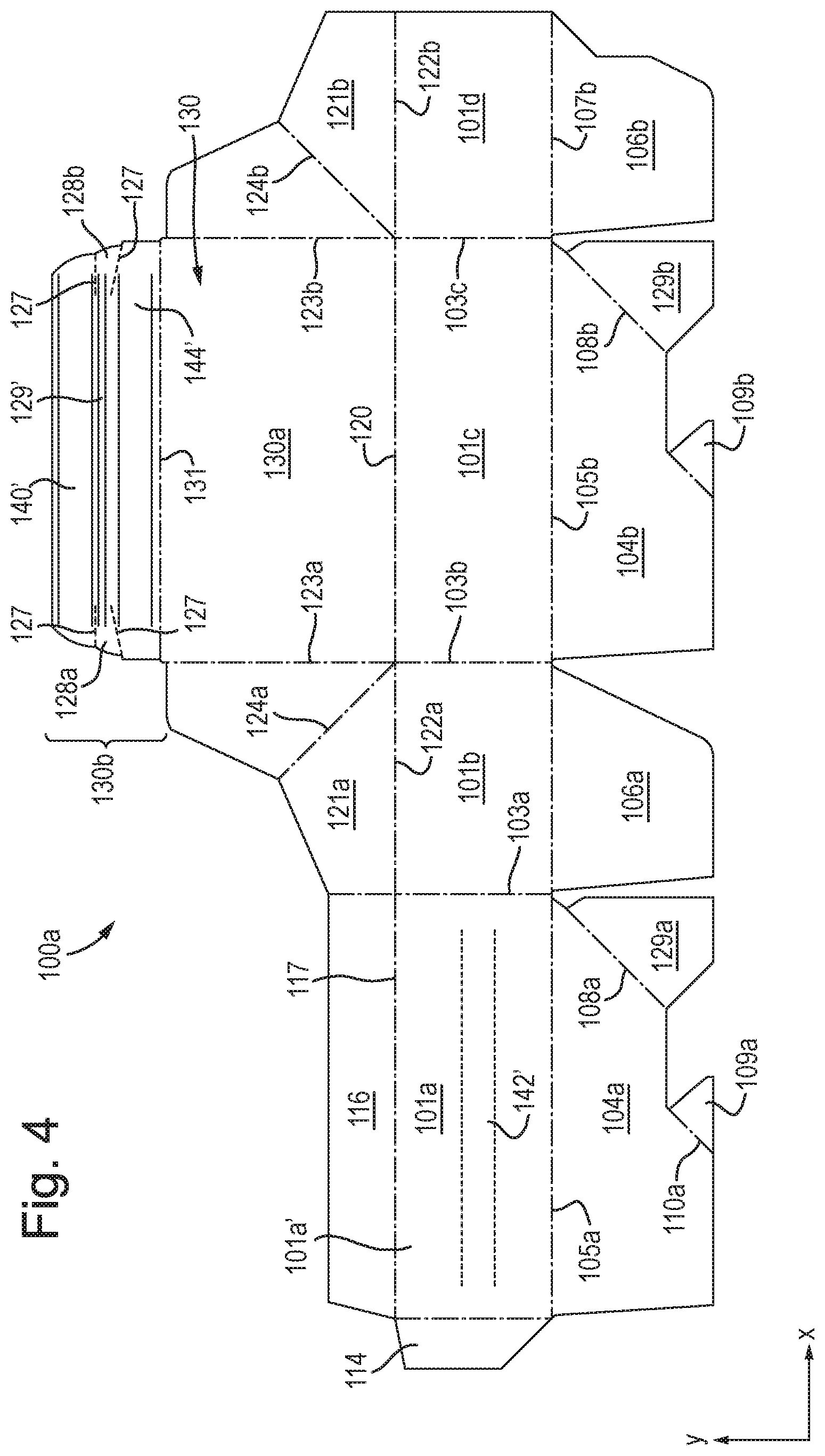
[0014] Each of the first and second adhesive regions comprises an adhesive substantially covered with a release liner. Thus, each adhesive region may be said to comprise an adhesive layer and a release liner layer. The adhesive of each adhesive region is in contact with the corrugated fibreboard. The release liners (or release "tapes") cover the adhesive of the respective adhesive region in order to prevent undesirable adhesion of the first and second adhesive regions to each other or to other substrates during storage, and to help prevent degradation of the adhesive during storage. The release liner typically comprises a heavily calendered paper base that has been coated with a silicone or fluoropolymer release (antiadhesive) coating that is in contact with the adhesive and allows the release liner to be removed when the packing case is to be sealed.
[0015] The release liner of each adhesive region substantially completely covers the adhesive of the respective adhesive region. Preferably, a portion of the release liner of each adhesive region laterally extends beyond the adhesive so as to allow for ease of removal.
[0016] Typically, the first and second adhesive regions are in the form of elongate strips so as to maximise the area over which the bond may be formed. Consequently, the adhesive of each adhesive region, and the corresponding release liner, is also in the form of an elongate strip. However, other geometries of the adhesive regions are envisaged, such as lines, or square or circular "patches" for example.
[0017] The first and second adhesive regions are positioned on respective surfaces of the corrugated fibreboard packing case. The first and second adhesive regions face each other and overlap when the lid is in the closed configuration.
[0018] In preferred embodiments, the first adhesive region is positioned on the lid of the packing case. In such embodiments, the first adhesive region is located on an inner surface of the lid, i.e. a surface of the lid that is not exposed to the external environment when the lid is in the closed configuration. Preferably, the second adhesive region is positioned on a side panel or the base of the packing case. The second adhesive region is located on an outer facing surface of the side panel or base (i.e. a surface of the side panel or base that is exposed to the external environment) so as to cooperate with ("face") the inner surface of the lid on which the first adhesive region is typically positioned.
[0019] In embodiments, the lid may comprise a lid main section and a lid extension flap integrally connected to the lid main section along a fold line, and wherein the first adhesive region is positioned on said extension flap. When the lid is in the closed configuration, the extension flap typically overlaps with a side panel or the base of the packing case.
[0020] In embodiments, one of the side panels may comprise a main section and an extension flap integrally connected to the main section along a fold line, and wherein the second adhesive region is positioned on said extension flap. In such scenarios, the extension flap is located at an end of the main section opposing the base of the packing case, and folds inwardly towards the interior volume of the packing case. The inner surface of the lid (on which the first adhesive region is typically positioned) then overlaps with the extension flap such that the first and second adhesive regions overlap.
[0021] In embodiments, the lid is integrally connected to one of the side panels along a lid fold line, and wherein the packing case further comprises a third adhesive region positioned inboard of both the first and second adhesive regions with respect to the lid fold line, said third adhesive region comprising an (typically pressure sensitive) adhesive substantially covered with a release liner. The lid fold line may be considered as a "hinge" about which the lid may be moved between its closed configuration and open configuration. The third adhesive region is positioned inboard of the first and second regions such that it is closer to the lid fold line ("hinge") along a path defined by the lid than either the first or second adhesive regions.
[0022] The third adhesive region preferably has the same configuration as the first and second adhesive regions described above (typically the adhesives used in the first, second and third adhesive regions are the same). In eCommerce applications, once an end user (typically a customer) has received the goods in the sealed packing case, he/she may wish to return some goods (for example if they are the wrong type/size or faulty). It is convenient, economical and environmentally friendly to return the goods in the same packing case as they were received in. Thus, once the sealed packing case (that has been sealed using the first and second adhesive regions) has been opened by the end user, it can be re-sealed using the third adhesive region. The user removes the release liner and adheres the adhesive of the third adhesive region to a surface of the packing case in order to maintain the lid in the closed configuration.
[0023] The third adhesive region being inboard of both the first and second adhesive regions with respect to the lid fold line advantageously ensures that it is positioned such that the lid may be returned to and adhered in the closed configuration even if the region of the lid where the first and second adhesive regions were initially adhered together is no longer usable (for example following damage in the opening of the packing case).
[0024] Although the third adhesive region preferably has the same configuration as the first and second adhesive regions (e.g. comprises the same adhesive and has the same geometry), it may differ to the first and second adhesive regions in geometry and/or the adhesive used.
[0025] The third adhesive region may be positioned on the lid of the packing case, or on one of the side panels or the base of the packing case. In embodiments, the packing case may comprise a fourth adhesive region positioned so as to overlap with the third adhesive region when the lid is in the closed configuration. Such a fourth adhesive region comprises an (typically pressure sensitive) adhesive and release liner as described above.
[0026] In embodiments, the lid may be integrally connected to one of the side panels along a lid fold line, and wherein the lid further comprises an opening section positioned inboard of the first adhesive region with respect to the lid fold line. The term "inboard" has the same meaning as described above. The opening section allows for ease of opening of the sealed packing case by the end user. The opening section is typically a removable section of the lid. As the opening section is positioned inboard of the first and second adhesive regions, upon removing the opening section, the lid may be returned to its open configuration (with the first and second adhesive regions remaining in the adhered state).
[0027] The opening section typically comprises a tear tape (e.g. Rippatape.RTM.) having a tear strength greater than that of the corrugated fibreboard, and/or a perforated section that may be torn by the user. The opening section typically extends between opposing edges of the lid such that on removal of the opening section, the remaining part of the lid that is still integrally connected to one of the side panels along the lid fold line is separated from the part of the lid that has been adhered using the first and second adhesive regions.
[0028] In scenarios where the packing case comprises both a third adhesive region and an opening section, the third adhesive region is positioned inboard of the first and second adhesive regions, and the opening section, with respect to the lid fold line.
[0029] Typically, the erected packing case has a substantially rectangular geometry when viewed in plan form. Other geometries of the erected packing case when viewed in plan form are envisaged however, for example a square or non-quadrilateral shapes.
[0030] Typically, the packing case comprises first, second, third and fourth side panels integrally connected together along fold lines, a base panel connected to a bottom end of each of the side panels along respective fold lines, the base panels defining the base of the packing case; and wherein, the lid is integrally connected to a top end of one of the side panels along a lid fold line. Throughout this specification, the term "fold line" may refer to a crease line, cut line, slit line, score line or other manipulation of the corrugated fibreboard that allows the corrugated fibreboard to fold in a desired manner, as will be understood by the skilled artisan.
[0031] Preferably, the packing case is formed from a (typically single) blank. Typically the blank is a die-cut blank, although alternatively the blank may be cut by a robotic machine or using a slotting and creasing machine (either a case maker or a printer slotter). The blank comprises opposing first and second surfaces, wherein the first adhesive region is positioned on the first surface and the second adhesive region is positioned on the second surface. Upon folding the blank during manufacture of the packing case, the relative orientations of the first and second surfaces having the first and second adhesive regions positioned thereon is such that when the lid is in the closed configuration, the first and second adhesive regions face each other and overlap.
[0032] The packing case is preferably collapsible such that it can be stored flat. This advantageously vastly reduces the space required to store the packing cases. The packing cases can then be erected when required.
[0033] In accordance with a second aspect of the invention there is provided a blank for a packing case, the blank having opposing first and second surfaces and comprising; a plurality of side panels, at least one base panel and a lid integrally connected together along fold lines such that the blank may be erected to define an enclosed interior volume of a packing case when the lid is in a closed configuration, wherein the blank comprises a first adhesive region on the first surface and a second adhesive region on the second surface, the first and second adhesive regions being arranged such that when packing case is in an erected configuration and the lid is in the closed configuration, the first and second adhesive regions overlap; wherein, each of the first and second adhesive regions comprises an adhesive substantially covered with a release liner, whereby when the blank is erected the release liners may be removed and the adhesives of the first and second adhesive regions adhered to each other to maintain the lid in the closed configuration.
[0034] The adhesive of the first and second adhesive regions is preferably a rubberised hot-melt pressure sensitive adhesive. An example of such an adhesive is H1625/6 available from Sealock Ltd., UK.
[0035] Preferably, the first adhesive region is positioned on the lid. The blank may comprise a third adhesive region as described above with reference to the first aspect. The blank may comprise a third adhesive region and a fourth adhesive region as described above with reference to the first aspect. The blank may comprise an opening section as described above with reference to the first aspect.
[0036] The blank is typically die-cut, although it is envisaged that the blank may be cut by robotic machine or by a slotting and creasing machine (either a case maker or a printer slotter). The blank is preferably formed from corrugated fibreboard, although other materials are envisaged such as carton board, pasted solid board, boxboard, rigid plastic or semi-rigid plastic.
[0037] In accordance with a third aspect of the invention there is provided a method for manufacturing a (preferably corrugated fibreboard) packing case, the method comprising: providing a (preferably die-cut) blank comprising a plurality of side panels, at least one base panel and a lid integrally connected along fold lines and arranged such that the blank may be erected to define an enclosed interior volume of a packing case when the lid is in a closed configuration, wherein the blank comprises opposing first and second surfaces having respective first and second regions arranged such that when the packing case is in an erected configuration, the first and second regions overlap when the lid is in the closed configuration; folding the blank such that the first and second regions on the opposed first and second surfaces are accessible from a common side of the folded blank; applying adhesive to the first and second regions; and, applying a release liner to each of the first and second regions so as to substantially cover the adhesive.
[0038] The blank is typically formed of corrugated fibreboard, although other materials are envisaged such as carton board, pasted solid board, boxboard, rigid plastic or semi-rigid plastic. The blank may be formed in a separate process (e.g. in a separate factory) to the method of the third aspect of the invention. In other embodiments, the method of the third aspect of the invention may comprise the initial step of forming the blank, preferably by die-cutting (although other means of forming the blank are envisaged as discussed above in relation to the second aspect).
[0039] When the packing case is in an erected configuration, the first and second regions overlap when the lid is in the closed configuration. The first and second regions also face each other when the lid is in the closed configuration. This means that the first and second regions are required to be on opposing surfaces of the blank. Thus, one way in which the adhesive and release liners may be applied to the first and second regions is to "flip" the blank at a stage of the manufacturing process such that the adhesive and release liners can be applied to the opposing surfaces. Another way would be to utilise apparatus positioned on opposing sides of (i.e. "above" and "below") the blank. However, these methods are inefficient.
[0040] The method of the third aspect of the invention thus advantageously comprises the step of folding the blank such that the first and second regions on the opposing first and second surfaces are accessible from a common side of the folded blank. This means that there is no requirement to "flip" the blank in order to apply the adhesive and release liners to the first and second regions, and the apparatus used for these application steps may be positioned on the common side (e.g. "above") the folded blank. This beneficially allows the method to be performed efficiently (i.e. without having to flip the blank) and with a high throughput rate. Typically, the method is performed as an in-line process on a production line comprising a plurality of in-line units that are configured to perform the steps of the method in a sequential manner. The ability to manufacture such packing cases (in particular the folding steps and application of the adhesive and release liners to the first and second regions) in a single in-line process is particularly advantageous, as this increases efficiency and throughput, reduces waste and minimises the footprint of the apparatus necessary for the manufacture.
[0041] Preferably, the step of folding comprises connecting at least two (e.g. side and/or base) panels of the blank together so as to form a partially assembled packing case that lies substantially flat, and wherein the first and second regions are accessible from a common side of the partially assembled packing case. In other words, during this step, the blank is folded and panels thereof connected together such that on completion of this stage of the manufacturing process the resulting partially assembled packing case lies substantially flat. The steps of applying adhesive to the first and second regions and applying a release liner to each of the first and second regions are then carried out on the substantially flat partially formed packing case in order to form the fully formed (collapsible) packing case.
[0042] The partially assembled packing case lies substantially flat. In other words it is in a "collapsed" form, typically due to folding along one of the fold lines.
[0043] The step of folding comprises connecting at least two panels of the blank together. The panels are preferably connected by gluing (using a "joining adhesive" such as PVA glue and/or a hot melt adhesive that is typically different to the adhesive applied to the first and second regions to form the adhesive regions), although other connecting means such as stapling or stitching may be used. The joining adhesive is typically different to the ("sealing") adhesive applied to the first and second regions to form the first and second adhesive regions. The glued and folded partially assembled packing cases may then be compressed in order to form a good bond in the glued regions and maintain the partially assembled packing cases in their substantially flat form.
[0044] Typically, the at least two panels that are connected together comprise two side panels that are connected together. Furthermore, the blank may comprise two or more base panels (in preferred embodiments the blank comprises a base panel connected to a bottom end of each of the side panels along respective fold lines) and the at least two panels that are connected together comprise two base panels that are connected together. Typically, the step of folding comprises connecting (e.g. gluing) two side panels together and connecting (e.g. gluing) at least two base panels together to form the partially assembled packing case.
[0045] Subsequent to the folding step, the adhesive used for sealing the packing case is applied to the first and second regions, typically by extrusion (using one or more applicator extruders), or by spraying (using one or more spray nozzles (e.g. slot nozzles)). It is also envisaged that applicator wheels may be used to apply the adhesive. The release liner is typically applied from a spool of release liner material and cut to the requisite size. The release liner is typically applied immediately after the application of the adhesive.
[0046] The adhesive that is applied to the first and second regions is preferably a rubberised hot-melt pressure sensitive adhesive. An example of such an adhesive is H1625/6 available from Sealock Ltd., UK
[0047] The method may further comprise the step of applying adhesive to a third region (typically the same adhesive as applied to the first and second regions), and applying a release liner to the adhesive of the third region in order to form a third adhesive region with the benefits discussed above. In such embodiments, the first, second and third regions are accessible from a common side of the partially assembled packing case. The method may further comprise applying adhesive and a release liner to a fourth region to form a fourth adhesive region.
[0048] In some embodiments, the method of the third aspect of the invention may comprise applying a tear tape to the partially assembled packing case to facilitate ease of opening of the sealed packing case. In such embodiments, the lid is integrally connected to one of the side panels along a lid fold line, and the tear tape is applied to an opening section positioned inboard of the first region with respect to the lid fold line, preferably where the opening section comprises a removable section of the lid. Such an opening section typically extends between opposing edges of the lid.
BRIEF DESCRIPTION OF THE DRAWINGS
[0049] The invention will now be described with reference to the figures, in which:
[0050] FIG. 1 is a perspective view of a corrugated fibreboard packing case according to a first embodiment of the invention;
[0051] FIG. 2 is a perspective view of the corrugated fireboard packing case according to the first embodiment, with the lid shown in the closed configuration;
[0052] FIG. 3 is a flow diagram outlining the main steps of a method for manufacturing a packing case according to the invention;
[0053] FIG. 4 is a diagram illustrating a blank used to manufacture the packing case of the first embodiment of the invention;
[0054] FIG. 5 is a diagram showing the packing case of the first embodiment of the invention during manufacture;
[0055] FIG. 6 is a perspective view of a corrugated fibreboard packing case according to a second embodiment of the invention, and;
[0056] FIG. 7 is a diagram illustrating a blank used to manufacture the packing case of the second embodiment.
DETAILED DESCRIPTION
[0057] FIG. 1 is a perspective view of an erected corrugated fibreboard packing case according to a first embodiment of the invention. The packing case has four side panels 101a, 101b, 101c and 101a (only side panels 101a and 101b are visible in the view of FIG. 1) that define a rectangular geometry when the case is viewed in plan form. However, in other embodiments, the side panels may have substantially the same dimensions such that the case is substantially square when viewed in plan form. Other, non-quadrilateral, geometries defined by the side panels are also envisaged.
[0058] The case further comprises a base (not visible in the view of FIG. 1) and a lid 130 integrally connected to side panel 101c (see FIG. 4) along fold line 120. In this embodiment, the lid 130 comprises a lid main panel 130a and a lid extension flap 130b integrally connected along fold line 131. FIG. 1 illustrates the case 100 with the lid 130 in an open configuration (i.e. the case is not sealed and the interior of the case is accessible). With the lid 130 in the open configuration, the desired goods can be packaged into the case--typically by an operator in a warehouse or packing facility--before closing the lid such the lid is in a closed configuration where the interior of the case is not accessible (illustrated in FIG. 2). With the lid in the closed configuration, the side panels, base and lid define an enclosed interior volume.
[0059] As shown in FIG. 1, side panel 101a comprises a (second) adhesive region 142 on its outer facing surface (i.e. the surface exposed to the external environment when the lid is in the open configuration). The adhesive region 142 is in the form of an elongate strip. The lid 130 comprises a corresponding (first) adhesive region 140 on the inner surface of the lid extension flap 130b. It is to be noted that as the first adhesive region 140 is on the inner surface of the lid extension flap, it is not visible in the views of FIGS. 1 and 2. However, the first adhesive region 140 is still highlighted in dashed lines for clarity of understanding.
[0060] The adhesive regions 140 and 142 are positioned such that when the lid is in the closed configuration, they substantially overlap and face each other, as shown in FIG. 2. Each adhesive region therefore has substantially the same geometry. In this embodiment, each adhesive region is in the form of an elongate strip. The direction of elongation is along the principal axis (i.e. axis of longest dimension) of the side panel 101a and lid extension flap 130b, thereby advantageously maximising the area over which adhesion takes place. However, in other embodiments, alternative geometries for the adhesive regions are envisaged, such as lines or square or circular geometry.
[0061] Each adhesive region 140, 142 comprises a pressure-sensitive adhesive that is applied onto the surface of the corrugated fibreboard. The adhesive is a pressure-sensitive hot-melt adhesive based on a rubber/resin blend (such as H1625/6 available from Sealock Ltd., UK), and the same adhesive is used for each of the first and second adhesive regions 140, 142 that are used to seal the packing case. Each adhesive region comprises a respective release liner substantially completely covering the adhesive. Release liner 152 of second adhesive region 142 is visible in the view of FIG. 1. Each release liner is thus preferably in the form of an elongate strip, and preferably extends laterally beyond the adhesive of its respective adhesive region such that a portion (152a) of the release liner is not adhered to the adhesive so as to allow for ease of removal of the release liner. The release liner comprises a paper substrate having a silicone or fluropolymer release (antiadhesive) coating that has a much lower adhesion strength to the adhesive than the corrugated fibreboard so as to enable ease of removal of the release liner from the adhesive.
[0062] When the case 100 is to be sealed (i.e. after being packed), an operator removes the release liner from each of the adhesive regions 140, 142 such that the adhesive is exposed in each adhesive region 140, 142. The operator then mates the exposed adhesive of the two adhesive regions 140, 142 by applying pressure to the lid extension flap 130b, thereby adhering the lid extension flap 130b to the outer facing surface of side panel 101a. This maintains the lid 130 in the closed configuration with a secure bond formed between the adhesives of the adhesive regions 140, 142.
[0063] Optionally, the lid extension flap 130b further comprises tabs 128a, 128b that oppose each other on opposing outer edges of the lid extension flap 130b. The tabs 128a, 128b are defined by perforations 127 extending inwards from the outer edges of the lid extension flap. An opening strip (illustrated at 129) extends between the tabs 128a, 128b. The tabs and opening strip are positioned inboard of the adhesive region 140 with respect to the fold line 120 where the lid is integrally connected to side panel 101c. Therefore, an end user, on receipt of the packing case, may easily open the packing case by pulling one or both of the tabs 128a, 128b so as to tear the corrugated fibreboard along the opening strip 129, separating the part of the lid having adhesive region 140 (which will still be adhered to adhesive region 142) from the remainder of the lid 130, thereby allowing the lid to be opened. This advantageously allows the lid to be easily opened by the end user without having to break the bond between adhesive regions 140 and 142. This also allows for any tampering of the case to be easily detected. In alternative embodiments, the packing case may comprise one tab 128 that may be used to open the lid along opening strip.
[0064] In this embodiment, the opening strip 129 comprises a tear tape on the inner surface of the lid extension flap 130b, with the tear tape having a greater tear strength than the corrugated fibreboard (the region of the tear tape 129 is highlighted for ease of understanding). In alternative embodiments the opening strip 129 may be defined by perforations extending between perforations 127 of the tabs 128a, 128b.
[0065] The lid extension flap 130b optionally further comprises a third adhesive region 144 positioned inboard of the first adhesive region 140 with respect to lid fold line 120, and on an inner surface of the lid extension flap 130b. (It is to be noted that as the third adhesive region 140 is on the inner surface of the lid extension flap, it is not visible in the views of FIGS. 1 and 2. However, the third adhesive region 144 is still highlighted for clarity of understanding.) In other words, when an end user opens the case by using opening strip 129, the remaining part of the lid extension flap 130b that is still integrally connected to lid main panel 130 comprises the third adhesive region.
[0066] In a similar manner to the first and second adhesive regions 140, 142, the third adhesive region 144 comprises a rubberised hot-melt pressure sensitive adhesive covered by a release liner. The adhesive and release liner of the third adhesive region are typically the same as those used for the first and second adhesive regions. The third adhesive region 144 advantageously allows the end user to re-seal the packing case 100 should they wish to (for example for returning items to the distributor) by removing the release liner and adhering the remaining section of the lid extension flap 130b to the surface of the side panel 101a using third adhesive region.
[0067] In this embodiment, the third adhesive region 144 is on the inner surface of lid extension flap 130b. However, in other embodiments (not shown), the third adhesive region may be positioned on the outer surface of side panel 101a. In such a scenario, the third adhesive region 144 is positioned inboard of the second adhesive region 142 with respect to the fold line 120 such that it cooperates with (i.e. overlaps with and faces) the remaining part of the lid extension flap 130b that is still integrally connected to lid main panel 130 after opening strip 129 has been used to open the case.
[0068] Unlike in the warehouse or facility in which the original packing and sealing of the cases takes place, the end user typically has ample time to ensure that a secure bond is formed when re-sealing the case using the third adhesive region. However, embodiments in which the side panel 101a comprises a fourth adhesive region (not shown) positioned so as to cooperate with (i.e. overlaps and faces) the third adhesive region (in the same manner as the first and second adhesive regions described above) are also envisaged for further security when re-sealing the packing case. The adhesive and release liner of such a fourth adhesive region are typically the same as those used for the first, second and third adhesive regions.
[0069] FIG. 3 is a flow diagram outlining the steps of a preferred method for manufacturing the packing case 100 described above with reference to FIGS. 1 and 2. The steps of the method will now be described with reference to FIGS. 4 and 5. The manufacture of the packing case 100 typically takes place on an in-line production line comprising a plurality of in-line units that are configured to (typically sequentially) perform the steps of the method. It will be understood that at least some of the method steps in FIG. 3 may be performed in an alternative order; for example steps S400 and S500 may be performed in the reverse order, or may be performed substantially simultaneously.
[0070] At step S100, a die-cut corrugated fibreboard blank 100a is provided. The blank may have been produced separately from the production line, or may be cut at a cutting unit on the same production line where the remainder of the method steps are performed. The blank 100a is illustrated in FIG. 4. All lengths in FIG. 4 are defined in the y-direction, and all widths are defined in the x-direction. The blank 100a is formed from a single piece of corrugated fibreboard, and has first and second opposing surfaces. The first ("top") surface is visible in FIG. 4, and the second ("bottom") surface opposes the first surface and is consequently not visible in FIG. 4.
[0071] The blank 100a comprises first 101a, second 101b, third 101c and fourth 101d side panels, integrally connected together along respective parallel fold lines 103a-c extending along the lengths of the side panels. Each side panel has substantially the same length. When erected the first 101a and third 101c side panels oppose each other, and second 101b and fourth 101d side panels oppose each other so as to define the side panels of the erected packing case 100. The folds 101a-c are defined such that the top surfaces of side panels 101a-d are on the interior of the erected packing case.
[0072] In the present embodiment, side panels 101a and 101c have a width which is greater than the width of side panels 101b and 101d such that when erected, the packing case 100 is substantially rectangular when viewed in plan form. However, in other embodiments, the side panels may each have the same width such that the packing case is substantially square when viewed in plan form. In further embodiments, non-quadrilateral geometries defined by the side panels are also envisaged.
[0073] The blank 100 comprises base panels 104a and 104b of a first type integrally connected to side panels 101a and 101c along respective fold lines 105a, 105b, and base panels 106a and 106b of a second type integrally connected to side panels 101b and 101d along respective fold lines 107a and 107b. The length of each of the base panels is substantially the same. Together, the base panels define the base of the erected packing case. Base panels 104a, 104b comprise lobed sections 109a and 109b integrally connected along respective fold lines 110a and 110b. When the packing case is fully erected, the lobed sections 109a, 109b deflect around each other by bending at the respective fold lines 110a and 110b. When the packing case is fully erected, the lobed sections 109a, 109b lie substantially flat on the base of the packing case and interlock with each other to prevent the base of the packing case from opening. The case can be collapsed by deflecting the lobed sections such that they no longer interlock.
[0074] The blank 100a comprises lid a 130 that is integrally connected to side panel 101c along fold line 120. As has been described above in relation to FIGS. 1 and 2, the lid comprises lid main panel 130a and lid extension flap 130b integrally connected to the lid main panel along fold line 131. As can be seen in FIG. 4, the lid extension flap 130b comprises first region 140' and third region 144'. These regions do not comprise adhesive at this stage of the process, and define the regions to which adhesive and release liner will be applied in order to form the first 140 and third 144 adhesive regions of the packing case. The first 140' and third 144' regions are on the top surface of the blank 100.
[0075] The lid extension flap 130b further comprises tabs 128a and 128b defined by perforations 127 as have been previously described. Opening strip region 129' (which does not yet comprise a tear tape) is also shown, with region 129' being located on the top surface of the blank 100a.
[0076] Side panel 101a comprises second region 142' to which adhesive and a release liner will be applied in order to form second adhesive region 142. The second region 142' is on the bottom surface of the blank 100a (and as such is illustrated in dashed lines). In other words, the second region 142' is on the opposing surface of the blank to the first region 140' and the third region 144'.
[0077] Side panel 101a comprises main section 101a' and first extension flap 114 connected thereto along fold line 115. The side panel 101a also comprises a second extension flap 116 integrally connected to the main section 101a' along fold line 117.
[0078] The blank 100a further comprises top inner panels 121a and 121b integrally connected to side panels 101b and 101d along respective fold lines 122a and 122b. Top inner panels 121a, 121b are also integrally connected to lid 130 along respective fold lines 123a, 123b. Top inner panels 121a, 121b further comprise respective fold lines 124a, 124b. When the lid 130 of the erected packing case is folded over, top inner panels 121a, 121b fold inward along fold lines 124a, 124b (i.e. into the enclosed volume of the packing case) such that they ensure good closure between the side panels 101b, 101d and the lid 130.
[0079] At step S200, the packing case is partially assembled from the blank. During this step, the gluing and folding processes necessary to provide the final packing case are carried out at respective gluing and folding unit(s) on the production line. However, neither the adhesives of the adhesive regions 140, 142, 144, nor the tear tape, are applied during this step.
[0080] In this embodiment, during step S200, glue is applied to the top surface of the region of side panel 101d that overlaps with extension flap 114 when the packing case is assembled, and to the top surfaces of glue regions 129a and 129b on base panels 104a, 104b at a gluing unit. The glue (or "joining adhesive") is typically PVA glue applied by spraying from nozzles. Alternatively, or in addition, a hot-melt adhesive (different to the adhesive used for adhesive regions 140, 142, 144) may be used, which is typically extruded.
[0081] The blank is then conveyed to folding unit which carries out the suitable folding operations such that the extension flap 114 is glued to the top surface of side panel 101d (i.e. the surface exposed to the internal environment when the packing case is erected). Gluing extension flap 114 to side panel 101d connects the outermost side panels (i.e. panels 101a, 101d), thereby connecting the side panels of the packing case.
[0082] The folding unit also performs the necessary folding operations such that the topsides of the glue regions 129a and 129b are glued to the undersides of base panels 106a, 106b.
[0083] It will be appreciated that the exact sequence of gluing and folding processes when partially assembling the packing case in step S200 may vary. For example, some folding steps may occur before application of the glue. It is to be noted that the gluing processes in partially assembling the packing case in step S200 are separate to the application of the adhesives that form the adhesive regions used to seal the packing case (described below).
[0084] These gluing and folding steps form a partially assembled packing case 100b, and are performed such that the partially assembled packing case has substantially flat form, as shown in FIG. 5. Here, the partially assembled packing case is provided in flat form by folding along fold lines 103b and 103c for example. The substantially flat partially assembled packing case then preferably enters a compression unit where it is held flat while the glue applied by the gluing unit sets and forms a bond. This may typically take between 1 and 10 minutes (e.g. for PVA glue) depending on temperature, relative humidity etc. If a hot melt adhesive is used in the gluing and folding process a significant bond is formed almost instantly (on the order of seconds).
[0085] As will be appreciated, in this flat form, the top surface of the lid 130 (i.e. the inner surface of the lid 130 when the case is erected) and the bottom surface of the side panel 101a (i.e. the outer facing surface of the side panel 101a when the case is erected) are accessible from the same side of the partially assembled packing case 100b. This advantageously means that the first 140', second 142' and third 144' regions are accessible from the same side of the partially assembled packing case 100b (in other words they are on the same side of the partially assembled packing case). This is in contrast to the blank 100a, where the first 140', second 142' and third 144' regions were not accessible from the same side of the blank.
[0086] At step S300, a rubberised hot-melt pressure sensitive adhesive is applied to the first 140', second 142' and third 144' regions at an adhesive application unit. The application of the adhesive is performed by applicator extruders or spray nozzles, and the adhesive application unit typically comprises separate applicator heads configured to apply adhesive to each region. (Alternatively, there may be a plurality of adhesive application units.) The adhesive is typically applied so as to substantially completely cover the respective region to which it is applied.
[0087] At optional step S400, a tear tape is applied to opening strip region 129' at a tear tape application unit.
[0088] At step S500, a release liner is applied to the adhesive in each of the first, second and third regions at respective release liner application units (or a single unit with multiple applicators). The release liner is typically applied from a spool on the release liner application unit, and cut to the appropriate size. Typically, the release liner is applied and cut such that a portion of the release liner laterally extends from the applied adhesive so as to "overhang" the adhesive. The overhanging part of the release liner allows for ease of peeling from the adhesive when the packing case is desired to be sealed.
[0089] In embodiments where a tear tape is applied, this may be performed substantially simultaneously with the application of the release liners in step S500, and may be applied by the same application unit(s).
[0090] The application of the adhesive and release liner to first 140', second 142' and third 144' regions, optionally together with a tear tape to opening strip region 129' forms the fully assembled (collapsed) packing case which may be erected as required.
[0091] Advantageously, as each of the regions 140', 142' and 144' (and 129') is accessible from a common (i.e. same) side of the (flat) partially assembled packing case, the adhesive application unit(s), release liner application unit(s) and tear tape application unit may be positioned on a common side of (e.g. "above") the production line, without the blank or the partially assembled packing case required to be turned over in order to apply the adhesives, release liners and tear tape. This beneficially increases the efficiency of the manufacturing process and reduces footprint of the production line. In particular, the steps of partially assembling the packing case (S200), and applying the adhesive, tear tape (where applied) and release liners (i.e. steps S300, S400 and S500) in a single in-line process is a particular advantage in the present invention.
[0092] FIG. 6 illustrates a corrugated fibreboard packing case 200 according to an alternative embodiment of the invention (with the lid 230 in an open configuration), and FIG. 7 illustrates a blank 200a that may be used to form the packing case 200 using the method of FIG. 3. Like reference numerals have been used to illustrate similar parts to those discussed above in the first embodiment.
[0093] In this embodiment, the lid 230 does not comprise a lid extension flap as in the first embodiment, and the length of the lid (defined along the y-axis in FIG. 7) is substantially equal to the width of side panel 210b (defined along the x-axis in FIG. 7).
[0094] As can be seen in FIG. 6, first adhesive region 240 is in the form of an elongate strip on the inner surface of the lid 230. The first adhesive region comprises an adhesive and a release liner 250 in the same manner as described in the first embodiment. In this embodiment, the second adhesive region 242 is positioned on extension flap 216 that is an integral part of side panel 201a. In other words, and as also shown in FIG. 7, side panel 201a comprises main section 210a' and extension flap 216 integrally connected thereto along fold line 217. The second adhesive region 242 is in the form of an elongate strip having substantially the same dimensions as the first adhesive region, and comprises an adhesive and release liner 252 in the same manner as described in the first embodiment. As with the first embodiment, the adhesives of the first and second adhesive regions of packing case 200 are the same (a rubberised hot-melt pressure sensitive adhesive such as H1625/6 from Sealock Ltd., UK).
[0095] As with the first embodiment, the first and second adhesive regions are such that when the lid is in the closed configuration (with the extension flap 216 folded inwards), the first and second adhesive regions overlap and face each other. Thus, when the packing case 200 of the second embodiment has been packed with the desired goods, the operator may remove the release liners 250, 252 from both the first and second adhesive regions and adhere the adhesives of the adhesive regions together in order to seal the packing case.
[0096] The lid 230 (optionally) further comprises tabs 228a and 228b having an opening strip 129 extending there between. The tabs 228a, 228b and opening strip 129 are located inboard of the first adhesive region 240 with respect to the fold line 220 integrally connecting side panel 201c and lid 230. The tabs and opening strip are illustrated in FIG. 7 but have been omitted from FIG. 6 for clarity purposes.
[0097] The packing case 200 of the second embodiment may be manufactured in the same way as described above in relation to the first embodiment, with an appropriate corrugated fibreboard blank 200a illustrated in FIG. 7. First region 240' and second region 242' corresponding to the first and second adhesive regions 240, 242 are located on opposing surfaces of the blank. However, on partially assembling the packing case (step S200), the first 240' and second 242' regions are transposed onto a common side of the flat partially assembled packing case, allowing for ease of application of the adhesive and release liners in the same manner as described above.
[0098] It will be noted that the base panels 204a, 206a, 204b and 206b of the second embodiment differ from the first embodiment. However, together they form the base of the erected packing case 200, as will be appreciated by the skilled artisan. In this embodiment, base panel 204b comprises protrusion 205a which cooperates with slot 205b at the bottom of side panel 201a when the packing case is erected so lock the protrusion 205a in place and provide rigidity to the base.
[0099] The packing cases of both the first and second embodiments have been described as having an opening strip to allow for easy opening of the sealed packing case. It will be appreciated that this feature is optional, and in some embodiments the packing case does not comprise such an opening strip, with the end user required to open the case by other means, for example by cutting.
* * * * *
D00000
D00001
D00002
D00003
D00004
D00005
XML
uspto.report is an independent third-party trademark research tool that is not affiliated, endorsed, or sponsored by the United States Patent and Trademark Office (USPTO) or any other governmental organization. The information provided by uspto.report is based on publicly available data at the time of writing and is intended for informational purposes only.
While we strive to provide accurate and up-to-date information, we do not guarantee the accuracy, completeness, reliability, or suitability of the information displayed on this site. The use of this site is at your own risk. Any reliance you place on such information is therefore strictly at your own risk.
All official trademark data, including owner information, should be verified by visiting the official USPTO website at www.uspto.gov. This site is not intended to replace professional legal advice and should not be used as a substitute for consulting with a legal professional who is knowledgeable about trademark law.