Cutting Tool Having Partially-removed Film Formed Thereon
AHN; Seung-Su ; et al.
U.S. patent application number 16/846439 was filed with the patent office on 2020-07-30 for cutting tool having partially-removed film formed thereon. This patent application is currently assigned to KORLOY INC.. The applicant listed for this patent is KORLOY INC.. Invention is credited to Seung-Su AHN, Sun-Yong AHN, Kyung-il KIM, Sung-Hyun KIM, Sung-Gu LEE, Je-Hun PARK.
| Application Number | 20200238403 16/846439 |
| Document ID | 20200238403 / US20200238403 |
| Family ID | 1000004752434 |
| Filed Date | 2020-07-30 |
| Patent Application | download [pdf] |


View All Diagrams
| United States Patent Application | 20200238403 |
| Kind Code | A1 |
| AHN; Seung-Su ; et al. | July 30, 2020 |
CUTTING TOOL HAVING PARTIALLY-REMOVED FILM FORMED THEREON
Abstract
The present invention relates to a cutting tool, which performs, like a drill or a ball end mill, cutting while rotating in a state in which the center of the tip end is in contact with a work material, and includes a wear-resistant layer formed at the tip end thereof, wherein a portion of the wear-resistant layer is selectively removed through tip end polishing from the center of the tip end of the drill or the ball end mill to a predetermined area, so as to restrain micro-brittle wear generated in an ultra-low speed region, and thus remarkably improving the cutting lifespan of the cutting tool such as the drill or the ball end mill.
| Inventors: | AHN; Seung-Su; (Cheongju-si, KR) ; PARK; Je-Hun; (Cheongju-si, KR) ; KIM; Kyung-il; (Cheongju-si, KR) ; KIM; Sung-Hyun; (Cheongju-si, KR) ; LEE; Sung-Gu; (Cheongju-si, KR) ; AHN; Sun-Yong; (Cheongju-si, KR) | ||||||||||
| Applicant: |
|
||||||||||
|---|---|---|---|---|---|---|---|---|---|---|---|
| Assignee: | KORLOY INC. Seoul KR |
||||||||||
| Family ID: | 1000004752434 | ||||||||||
| Appl. No.: | 16/846439 | ||||||||||
| Filed: | April 13, 2020 |
Related U.S. Patent Documents
| Application Number | Filing Date | Patent Number | ||
|---|---|---|---|---|
| 15109656 | Jul 4, 2016 | |||
| PCT/KR2015/003875 | Apr 17, 2015 | |||
| 16846439 | ||||
| Current U.S. Class: | 1/1 |
| Current CPC Class: | B23B 2224/32 20130101; B23C 2228/10 20130101; B23B 2228/36 20130101; B23B 2228/10 20130101; B23C 5/16 20130101; B23B 2224/04 20130101; B23C 5/1009 20130101; B23C 2224/04 20130101; B23C 2224/32 20130101; C23C 28/044 20130101 |
| International Class: | B23C 5/10 20060101 B23C005/10; C23C 28/04 20060101 C23C028/04; B23C 5/16 20060101 B23C005/16 |
Foreign Application Data
| Date | Code | Application Number |
|---|---|---|
| Apr 23, 2014 | KR | 10-2014-0048442 |
Claims
1. A cutting tool formed in a columnar shape to cut a work material by being rotated while a center of a tip end thereof is in contact with the work material, wherein the base material for the tip end of the cutting tool is a sintered alloy, wherein a wear-resistant layer is formed on the tip end and has a partially removed region which is not a result of cutting the work material, wherein the partially removed region relative to a non-removed region ranges 0.01 to 0.8 in radius from the center of the tip end.
2. The cutting tool of claim 1, wherein the cutting tool is a drill or a ball end mill.
3. The cutting tool of claim 1, wherein the wear-resistant layer is formed in a single-layered or a multi-layered film.
4. The cutting tool of claim 1, wherein the wear-resistant layer comprises one or more layers of the thin film which comprises at least one metallic element selected from elements of IVa, Va or VIa group in the periodic table, Al or Si, and at least one non-metallic elements selected from N, C, or O.
5. The cutting tool of claim 1, wherein the wear-resistant layer comprises a TiCN layer or Al.sub.2O.sub.3 layer.
Description
CROSS REFERENCE TO PRIOR APPLICATIONS
[0001] This application is a division of U.S. patent application Ser. No. 15/109,656 filed Jul. 4, 2016, which is the National Stage Application of PCT International Patent Application No. PCT/KR2015/003875 filed on Apr. 17, 2015, under 35 U.S.C. .sctn. 371, which claims priority to Korean Patent Application No. 10-2014-0048442 filed on Apr. 23, 2014, which are all hereby incorporated by reference in their entirety.
TECHNICAL FIELD
[0002] The present invention relates to a cutting tool having a layer partially removed through a tip end polishing, and more particularly, to a cutting tool which performs, like a drill or a ball end mill to cut while being rotated in a state in which the center of the tip end is in contact with a work material, and includes a wear-resistant layer formed at the tip end thereof, wherein a portion of the wear-resistant layer is selectively removed through tip end polishing from the center of the tip end of the drill or the ball end mill to a predetermined area, so as to restrain micro-brittle wear generated in an ultra-low speed region, thus remarkably improving the cutting lifespan of the cutting tool such as the drill or the ball end mill.
BACKGROUND ART
[0003] A drill is a cutting tool used to cut circular holes in a workpiece. Cutting blades of the drill are spirally formed along an outer circumferential portion of a rod-shaped material which is made of steel or super hard alloy, and the tip end of the drill is formed in a conical shape.
[0004] A ball end mill has a shape similar to the drill and has a ball-shaped tip end, and is thereby a tool mainly used to cut a curved surface.
[0005] Such tools, like drills or ball end mills, have a conical tip end or a ball-shaped tip end the center portion of which is in contact with a work material during cutting, and performs the cutting while being rotated about the center portion.
[0006] To improve the cutting lifespan, a single layer or a multi-layered wear-resistant layer which is formed of a hard material, such as TiCN, TiAlN, TiAlCrN, or Al.sub.2O.sub.3, is formed on a portion in which cutting is really performed, in the drill or a ball end mill.
[0007] When a tool such as a drill or a ball end mill is rotated, since a tip end and a cutting blade which are in contacting with a working material have speeds increased proportional to a value of a radius R from a center point which is a base point, the center point is in contact with the work material with a low speed, and the farther a portion from the center points, the higher the speed of the portion in contact with the work material.
[0008] Furthermore, the center portions of a drill and a ball end mill are in contact with a work material with a ultra-low speed, but in these ultra-low speed region, so-called micro-brittle wear is generated due to fatigue, and particularly, a high-pressure formed by a high feed speed in high-feed drilling functions to accelerate the micro-brittle wear of the center portion of a bottom cutting edge, and this becomes a main cause for degrading a tool lifespan of a drill or a ball end mill.
[0009] Also, a cover layer for additional decoration or for identifying whether to use is also formed on a wear-resistant layer in a cutting tool on which a wear-resistant layer is formed, and when the cover layer is thus formed, the formed cover layer should be easily removed without damage to the wear-resistant layer. Korean Patent Application No. 2006-0130196 discloses a technical feature in which a separation layer is additionally provided between the wear-resistant layer and the cover layer such that the cover layer is easily detached.
[0010] However, the technical feature is disclosed to remove the damage to the wear-resistant layer when the cover layer is removed before performing a main cutting work, not to provide a concept of improving a cutting lifespan by peeling off the wear-resistant layer itself.
DISCLOSURE OF THE INVENTION
Technical Problem
[0011] The purpose of the present invention is to provide a cutting tool capable of preventing the decrease in a cutting lifespan of a cutting tool caused by micro-brittle wear generated in a cutting tool such as a drill or a ball end mill.
Technical Solution
[0012] According to an aspect of the present invention, provided is a cutting tool formed in a columnar shape to cut a work material by being rotated while a center of a tip end thereof is in contact with the work material, wherein the base material for the tip end of the cutting tool is a sintered alloy, a wear-resistant layer is formed on the tip end, and a portion of or the entirety of the wear-resistant layer is removed within a distance of 0.01 R to 0.8 R (R: a radius of the column-shaped tool) from a center of the tip end.
[0013] According to another aspect of the present invention, provided is cutting tool formed in a columnar shape to cut a work material by being rotated while a center of a tip end thereof is in contact with the work material, wherein the tip end comprises one or more detachable and indexible inserts, the inserts each have a sintered alloy as a base material, a wear-resistant layer is formed on a surface of each insert, and a portion of or the entirety of the wear-resistant layer is removed within a distance of 0.01 R-0.8 R (where, R is a radius of the column-shaped tool) from the rotation center of the tip end.
Advantageous Effects
[0014] According to the present invention, a portion of a wear-resistant layer formed on a tip end of a tool such as a drill or a ball end mill is selectively removed within a distance of 0.01 R-0.8 R (where, R is the radius of the column-shaped tool) from a center of a tip end, so that wear and the propagation of the wear caused by micro-brittle wear typically generated in a drill or a ball end mill are prevented, and the cutting lifespan of a drill or a ball end mill can thereby be remarkably improved.
[0015] Also, according to the present invention, a portion of a wear-resistant layer formed on a clearance surface of an insert detachably fastened to a tip end of a tool such as a drill or a ball end mill is selectively removed within a distance of 0.01 R-0.8 R (where, R is a radius of the column-shaped tool) from the center of the tip end, and therefore, wear and the propagation of the wear caused by micro-brittle wear generated during cutting are prevented, and the lifespan of an insert can thereby be remarkably improved.
BRIEF DESCRIPTION OF THE DRAWINGS
[0016] FIG. 1 is a view illustrating a "tool radius R" in a drill having one or more fixed indexible inserts which can be attached/detached on a shank part and a tip end of a column-shaped drill body.
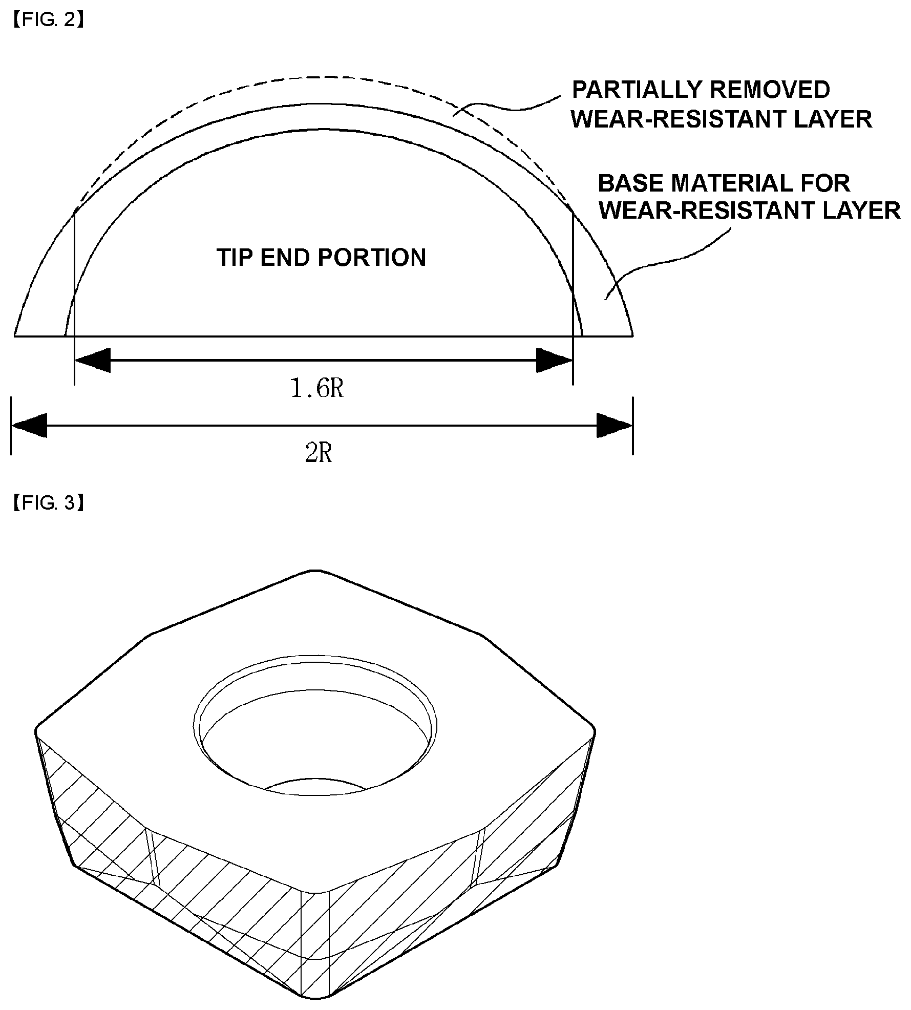
[0017] FIG. 2 is a schematic view illustrating a tip end in which a wear-resistant layer is optionally removed according to the present invention.
[0018] FIG. 3 is a schematic view illustrating a state (shadowed portion in the drawing) in which a wear-resistant layer formed in a clearance surface of an insert fastened to a drill in an indexible manner has been removed.
[0019] FIG. 4 is a photograph showing a center and a periphery of a tip end of a drill after performing drilling by means of a drill having a partially removed wear-resistant layer according to example 1 of the present invention.
[0020] FIG. 5 is a photograph showing a center and a periphery of a tip end of a drill after performing drilling by means of a drill having a partially removed wear-resistant layer according to example 2 of the present invention.
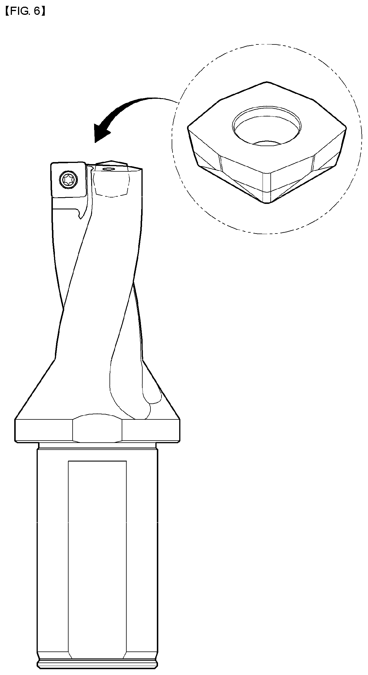
[0021] FIG. 6 is a perspective view illustrating a process of fixing two or more detachable and indexible inserts to a tip end of a shank part and a column-shaped drill body.
[0022] FIG. 7 illustrates photographs showing states of inserts after performing cutting tests (130 holes) by means of drills provided with inserts according to example 3 and comparative example 5 of the present invention.
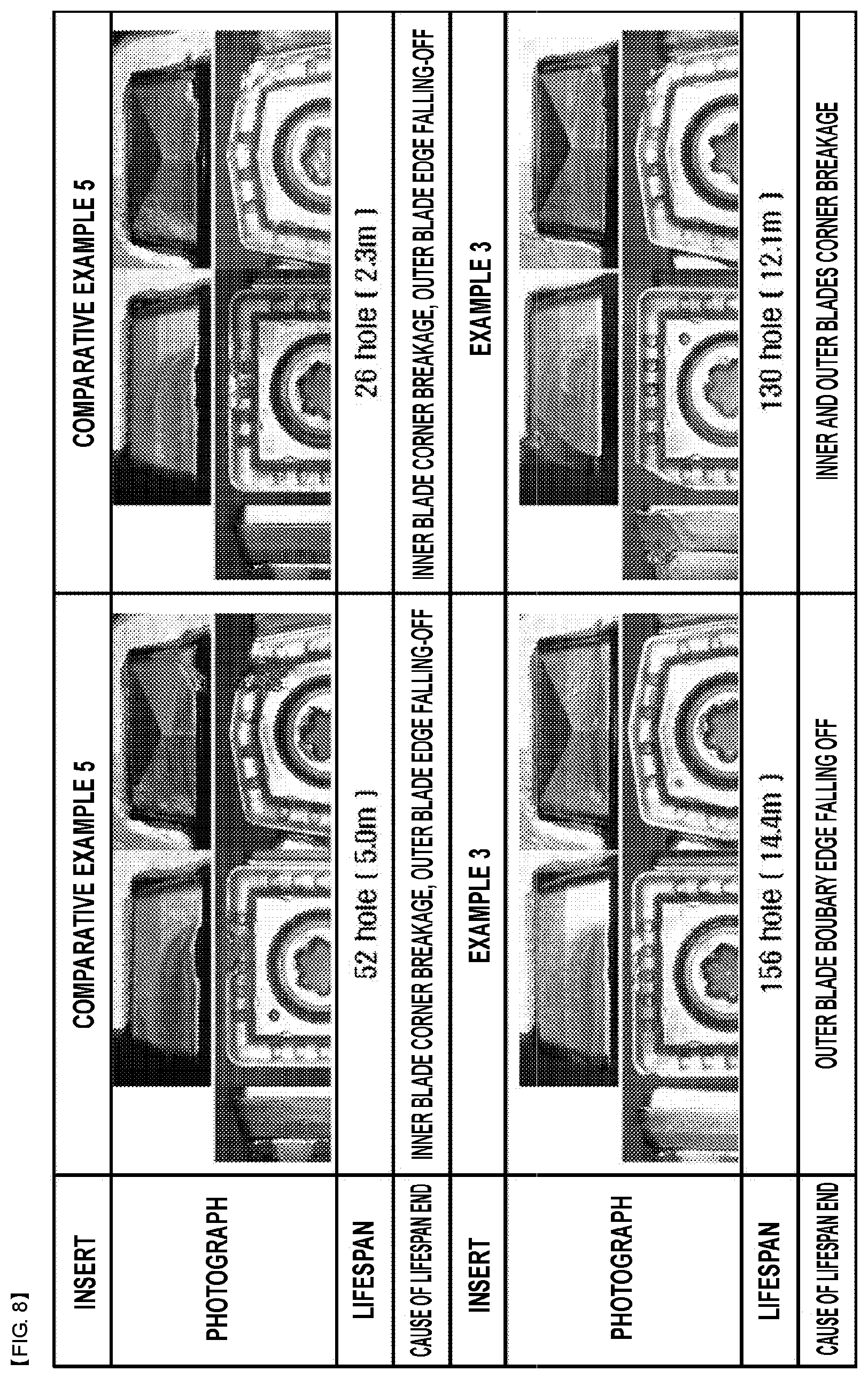
[0023] FIG. 8 illustrates photographs showing a number of drilled holes until an end of lifespan, causes of the end of lifespan, and states of inserts after performing cutting tests under a different cutting condition by means of drills provided with inserts according to example 3 and comparative example 5 of the present invention.
[0024] FIG. 9 is a photograph showing a center and a periphery of a tip end of a drill after performing drilling by means of a drill having a wear-resistant layer formed therein according to comparative example 1.
[0025] FIG. 10 is a photograph showing a center and a periphery of a tip end of a drill after performing drilling by means of a drill having a wear-resistant layer formed therein according to comparative example 2.
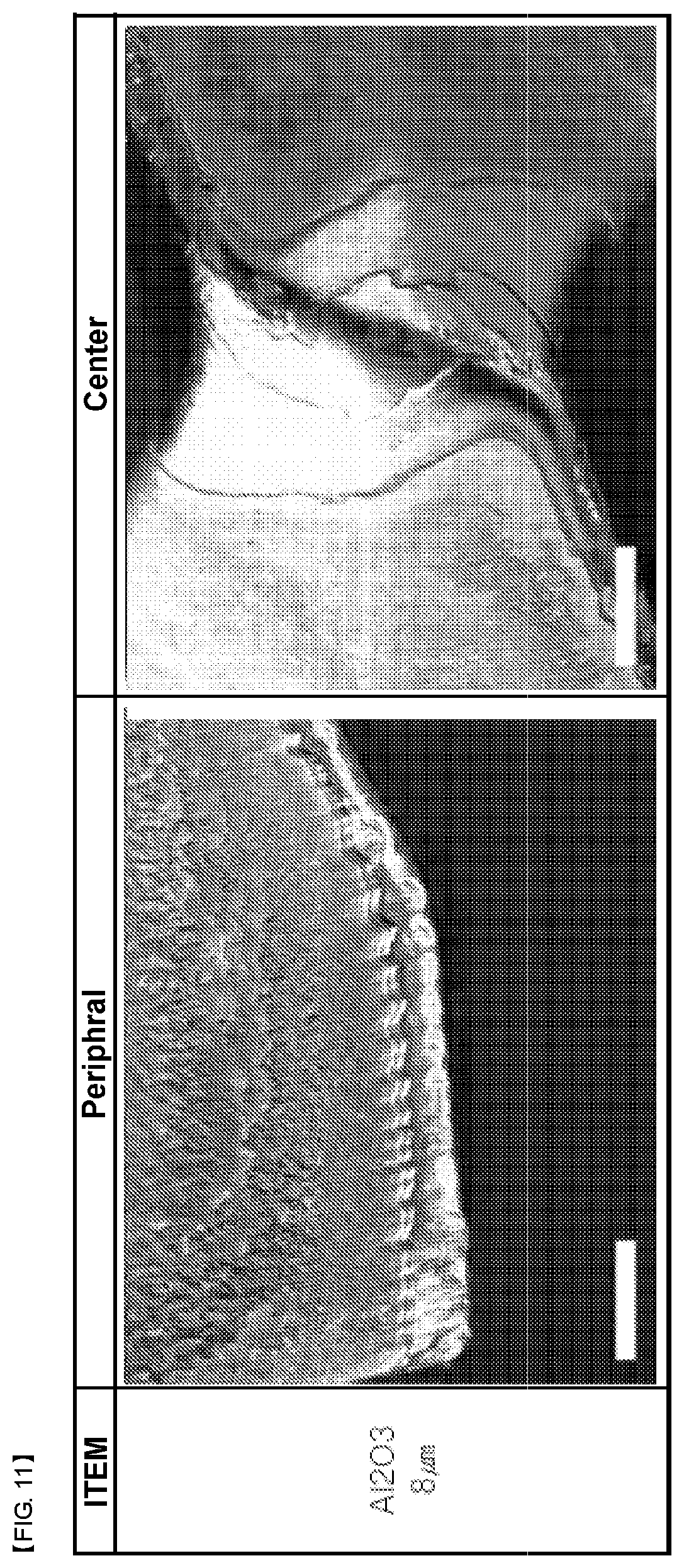
[0026] FIG. 11 is a photograph showing a center and a periphery of a tip end of a drill after performing drilling by means of a drill having a wear-resistant layer formed therein according to comparative example 3.
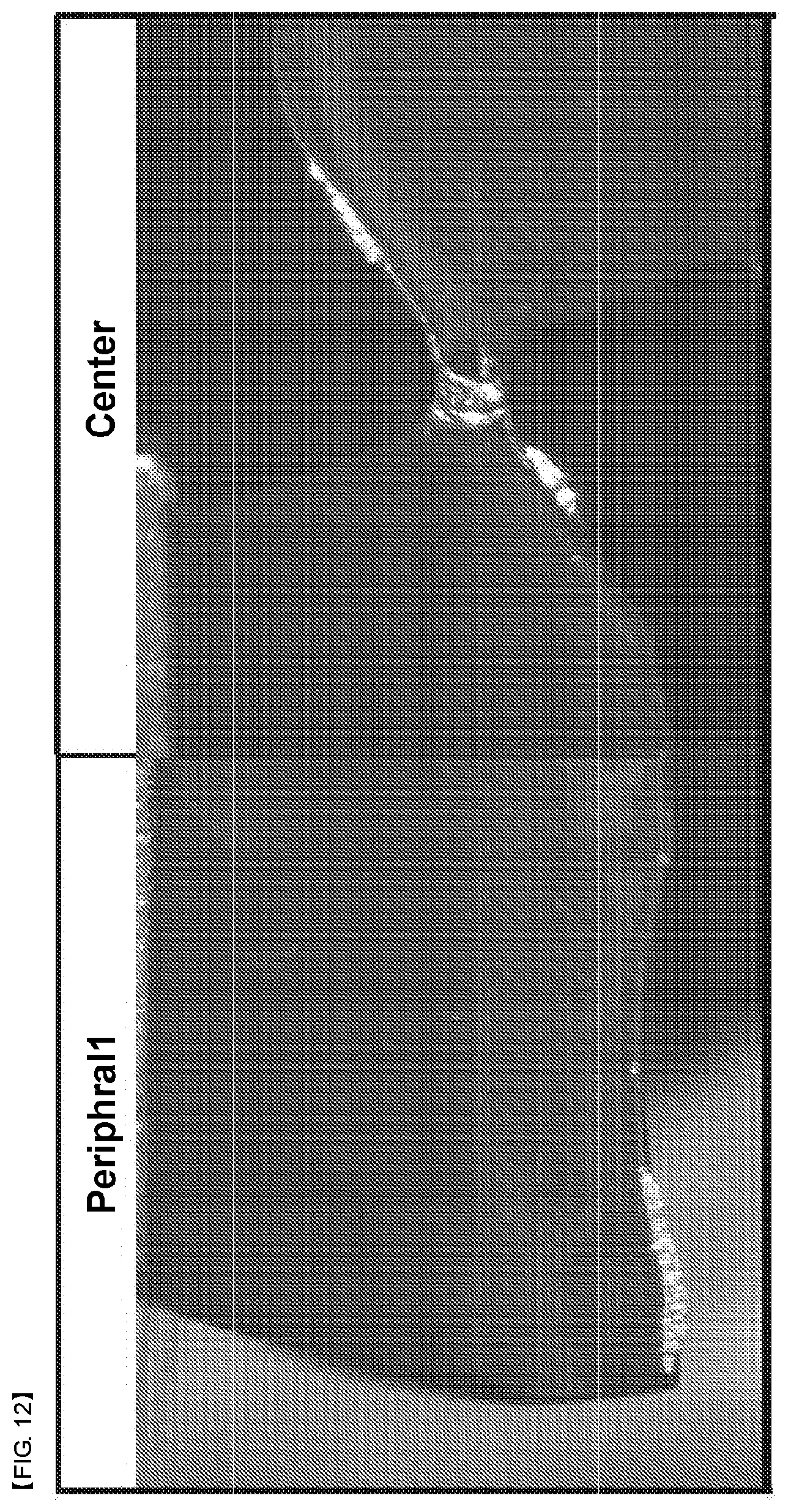
[0027] FIG. 12 is a photograph showing a center and a periphery of a tip end of a drill after performing drilling by means of a drill having a wear-resistant layer formed therein according to comparative example 4.
MODE FOR CARRYING OUT THE INVENTION
[0028] Hereinafter, embodiments of the present invention will be described in detail with reference to the accompanying drawings. However, exemplary embodiments of the present invention that will be described below may be modified into various forms, and the scope of the present invention should not be construed as limited to the embodiments to be described below in detail. The embodiments of the present invention are provided so that this disclosure will be more completely described to those skilled in the art.
[0029] In the present invention, a "tool radius R" of a common drill or a common end mill are radii of a column part of a column-shaped tool and means a radius in case of a circular shape, and means the radius of an inscribing circle in case of a polygonal shape.
[0030] Particularly, in case of a drill or an end mill provided with an indexible insert, as illustrated in FIG. 1, the "tool radius R" is the radius of a column-shaped tip end, means a radius in case of a circular shape, and means the radius of an inscribing circle in case of a polygonal shape.
[0031] As a result of research for solving the decrease in a tool lifespan due to micro-brittle wear generated in an ultra-low speed region at a central part during cutting by using a drill or a ball end mill, and due to a high pressure formed during a high-feed cutting, the inventors of the present invention discovered that cutting lifespan may be improved by restraining micro-brittle wear when a tip end polishing, in which a portion of wear-resistant layer formed at a bottom cutting edge part including a ultra-low speed region of the tip end central part of the drill is partially removed within a range of 0.01 R to 0.8 R in radius (1.6 R in diameter) from the center of the tip end, is performed through a process such as lapping as illustrated in FIG. 2.
[0032] Also, as illustrated in FIG. 3, it is discovered that when a portion of or the entirety of a wear-resistant layer formed on a clearance surface belonging to an ultra-low speed region during rotational cutting in an insert detachably fastened to a tip end of a drill is removed, more specifically, when a wear-resistant layer is formed on clearance surfaces of one or more inserts which are fastened in a column central part of the drill, and a partial or entire portion of the wear-resistant layer is removed within a range of 0.01 R to 0.8 R in radius from a rotation center through a process such as polishing or lapping, the micro-brittle wear is restrained and the cutting lifespan of the inserts can thereby be improved.
[0033] When the water-resistant layer is formed in a single layer, a portion thereof can be removed, or when formed in a multilayer, a portion of or the entirety of each layer constituting the multilayer can be removed. Here, when the ratio of the thickness of the removed thin film to the total thickness of the wear-resistant layer is about 1-90% at a position at which the thin film is maximally removed, the effect of the present invention can be achieved, but the thickness is preferably removed by 5% to 30%.
[0034] Also, in case of a clearance surface detachably fastened to the tip end of the drill, when about 1-100% of the total thickness of the wear-resistant layer is removed, the effect of the present invention can be achieved, but the thickness of the thin film is preferably removed by 5% to 30%.
[0035] The removed region of the wear-resistant layer should be within a range of 0.01 R to 0.8 R from the center of the tip end. This is because when the removed region of the wear resistant layer exceeds 0.8 R, the lifespan of a cutting tool is decreased due to decrease in wear resistance, and when a region of less than 0.01 R is removed, it is difficult to sufficiently restrain the micro-brittle wear. A desirable range of removing the wear-resistant layer is 0.02 R to 0.6 R, and more desirable range of removing the wear-resistant layer is 0.02 R to 0.5 R.
[0036] The cutting tool may be a drill or a ball end mill, but the inventive concept of the present invention includes removing a predetermined region about a central portion of contact in a cutting tool which performs a cutting similar to the drill or the ball end mill and in which the wear and propagation of the wear are generated in a similar mechanism.
[0037] The wear-resistant layer may be formed of a single-layered thin film or a multi-layered thin film, and the single layer or the multilayer includes at least one thin film containing at least one kind of element selected from metallic elements of IVa, Va or VIa group in the periodic table, Al, or Si, and at least one kind of non-metallic element selected from N, C, or O. For example, the wear-resistant layer may contain TiCN, TiAlN, TiAlCrN, or Al.sub.2O.sub.3.
[0038] Hereinafter, the present invention will be described in more detail through exemplary examples of the present invention and comparative examples thereof.
Example 1
[0039] A super hard alloy containing 10% of Co was used as a base material, was then cut in a drill shape of model number TPD150B of Korloy Inc., and a wear-resistant layer was formed on a surface of the drill by depositing a TiAlCrN thin film in a thickness of about 5 .mu.m by using a TiAlCr target through an arc ion plating method which is a physical vapor deposition.
[0040] A tip end polishing was then performed with respect to the TiAlCrN thin film up to about 0.2 R from the center portion by jetting a media (a composite grinding agent including diamond particles, and polymer particles) with a pressure of 2 bar for 10 seconds by using a micro-blasting apparatus, and thereby the wear-resistant layer was partially removed as illustrated in FIG. 2.
[0041] Drilling of 336 holes is then performed, by using a drill for which the tip end polishing is performed as mentioned above, under a cutting speed of 100 m/min, a feed per blade of 0.25 mm/tooth, a hole depth of 50 mm, and a wet cutting condition using SCM440 as a work material.
[0042] FIG. 4 is a photograph showing a center and a periphery of a tip end of a drill after performing drilling by means of a drill having a partially removed wear-resistant layer according to example 1 of the present invention.
[0043] As shown in FIG. 4, any split or damage to the thin film is rarely observed in the tip end or the drill according to example 1, and also in a surrounding edge portion, non-uniform damage to the thin film is rarely observed.
Example 2
[0044] A tip end polishing was performed up to about 0.2 R at a central portion with respect to a commercial drill of Korloy Inc. (a model number TPD130B and a kind of a coated layer PC5300 (TiAlN-system and thin film thickness of about 3 .mu.m)) by jetting a media (a composite grinding agent including diamond particles, and polymer particles) with a pressure of 2 bar for 10 seconds by using an aero-lapping device, and thereby the wear-resistant layer was partially removed as illustrated in FIG. 2A.
[0045] Drilling of 570 holes was performed, by using a drill for which the tip end polishing is performed as mentioned above, under a cutting speed of 100 m/min, a feed per blade of 0.25 mm/tooth, a hole depth of 50 mm, and a wet cutting condition using SCM440 as a work material.
[0046] FIG. 5 is a photograph showing a center and a periphery of a tip end of a drill after performing drilling by means of a drill having a partially removed wear-resistant layer according to example 2 of the present invention.
[0047] As illustrated in FIG. 5, the split or damage to the thin film was rarely observed in the tip end of the drill according to example 2 of the present invention, and a relatively stable wear behavior was shown in comparison with comparative example 4 in which the wear-resistant layer is not partially removed from the same product also in a surrounding edge part.
Example 3
[0048] A clearance surface (a shadowed portion in the drawing) of an insert illustrated in FIG. 3 was polished with respect to a product of Korloy Inc. with a model number XOMT07T205-LD and a kind of a coated layer PC5335 to which a TiAlCrN thin film is applied by jetting with a pressure of 2 bar for 10 seconds by using an aero-lapping device, and thereby the wear-resistant layer on a side surface of an insert was partially removed. Through this process, the thickness of the thin film on the clearance surface of the insert was removed by about 3-10%.
[0049] The insert according to example 3 prepared as the above was mounted to a drill holder having the diameter of 20 mm as illustrated in FIG. 6, and a cutting test was performed under a cutting condition of: a speed of 150 m/min, a feed per revolution of 0.1 mm/rev, a penetration depth of 90 mm, and a wet condition, using SCM440 as a work material.
[0050] As illustrated on the left side of FIG. 7, it can be understood from the state of the insert after drilling 130 holes that the insert according to example 3 of the present invention has an improved chipping-resistance and wear-resistance of the clearance surface in comparison with comparative example 5 under the above-mentioned cutting condition.
[0051] Next, the insert according to example 3 was mounted to a drill holder having the diameter of 20 mm, and a cutting test was then performed under a cutting condition: a speed of 120 m/min, a feed per revolution of 0.08 mm/rev, a penetration depth of 90 mm, a wet condition, using STS304 as a work material.
[0052] As illustrated in FIG. 8, while the lifespan ended at an average of 40 holes in case of the insert according to comparative example 5, the lifespan ended at an average of 140 holes or more in case of the insert according to example of the present invention, and therefore, it can be understood that the lifespan in the example 3 is remarkably improved than that in the comparative example 5.
Comparative Example 1
[0053] A super hard alloy containing 10% of Co was used as a base material, was then cut in a drill shape of model number TPD150B of Korloy Inc., and a wear-resistant layer was formed on the surface of the drill by depositing a TiAlCrN thin film at a thickness of about 5 .mu.m by using a TiAlCr target through an arc ion plating method which is a physical vapor deposition.
[0054] By means of the drill on which the wear-resistant layer is formed as described above, 336 holes were drilled under the same condition as the examples.
[0055] FIG. 9 is a photograph showing a center and a periphery of a tip end of a drill after performing drilling by means of the drill having a wear-resistant layer formed thereon according to comparative example 1.
[0056] As illustrated in FIG. 9, a thin film is peeled off in a spiral shape at the tip end of the drill according to comparative example 1, substantial deformation is also observed in a base material on a layer under the thin film, and the damaged thin film is shown to be substantially propagated to a periphery.
[0057] When comparing this result with that in the examples of the present invention, although comparative example 1 has the same condition as example 1 of the present invention except that only the tip end polishing was not performed, it can be understood that there is a remarkable difference in cutting performance.
Comparative Example 2
[0058] A super hard alloy containing 10% of Co was used as a base material, was then cut in a drill shape of model number TPD150B of Korloy Inc., and a wear-resistant layer was formed on the surface of the drill by depositing a TiAlN thin film at a thickness of about 3 .mu.m by using a TiAl target through an arc ion plating method which is a physical vapor deposition.
[0059] By means of the drill on which the wear-resistant layer is formed as described above, drilling was performed under the same condition as the examples.
[0060] FIG. 10 is a photograph showing a center and a periphery of a tip end of a drill after performing drilling by means of the drill having a wear-resistant layer formed thereon according to comparative example 2.
[0061] As illustrated in FIG. 10, it is not observed that a thin film is peeled off in a spiral shape at the tip end of the drill according to comparative example 2, but it is observed that wear was generated irregularly at peripheral edge portions.
Comparative Example 3
[0062] A super hard alloy containing 10% of Co was used as a base material, was then cut in a drill shape of model number TPD150B of Korloy Inc., and a wear-resistant layer having a total thickness of about 8 .mu.m was formed on the surface of the drill by forming a MT-TiCN thin film of 4 .mu.m and an Al.sub.2O.sub.3 thin film of 4 .mu.m through a chemical vapor deposition.
[0063] By means of the drill on which the wear-resistant layer is formed as described above, drilling was performed under the same condition as the examples.
[0064] FIG. 11 is a photograph showing a center and a periphery of a tip end of a drill after performing drilling by means of the drill having a wear-resistant layer formed thereon according to comparative example 3.
[0065] As illustrated in FIG. 11, it is also observed that a thin film is peeled off in a tornado-like shape at the tip end of the drill according to comparative example 3, and that wear was also generated irregularly at peripheral edge portions.
Comparative Example 4
[0066] Drilling was performed under the same condition as example 2 by means of a commercial drill (model number TPD130B, coating layer type PC5300 (TiAlN, thin film thickness of about 3 .mu.m) from Korloy Inc.
[0067] FIG. 12 is a photograph showing a center and a periphery of a tip end of a drill after performing drilling by means of the drill having a wear-resistant layer formed thereon according to comparative example 4.
[0068] As illustrated in FIG. 12, the tip end of the drill according to comparative example 4 shows a damaged shape of the original shape due to progress of wear and wear is also widely observed at peripheral edge portions.
Comparative Example 5
[0069] Cutting test was performed under the same condition as that in example 3 to compare comparative example 5 with example 3 by using a product from Korloy Inc. with a model number XOMT07T205-LD and a material type PC5335, on which the polishing with respect to the clearance surface of an insert as in example 3 was not performed, and as illustrated in FIGS. 7 and 8, it can be understood that the cutting performance is remarkably decreased in comparison with that in example 3.
[0070] Form the results above, it can be understood that when tip end polishing according to an embodiment of the present invention is performed, micro-brittle wear generated in a ultra-low speed region in a central portion during cutting by a drill or a ball end mill can be decreased, and thus the lifespan of a tool, such as a drill or a ball end mill, which cuts a work material while the center of the tip end of the tool contacts the work material, can be improved.
[0071] Also, it can be understood that when a wear-resistant layer is partially removed by partially polishing a clearance surface of an insert detachably fastened to a tip end, micro-brittle wear occurring in a ultra-low speed region in a central portion during rotational cutting can be decreased, and thus the lifespan of the insert tool which cuts a work material while the center of the tip end of the tool contacts the work material, can be remarkably improved.
* * * * *
D00000
D00001
D00002
D00003
D00004
D00005
D00006
D00007
D00008
D00009
D00010
D00011
XML
uspto.report is an independent third-party trademark research tool that is not affiliated, endorsed, or sponsored by the United States Patent and Trademark Office (USPTO) or any other governmental organization. The information provided by uspto.report is based on publicly available data at the time of writing and is intended for informational purposes only.
While we strive to provide accurate and up-to-date information, we do not guarantee the accuracy, completeness, reliability, or suitability of the information displayed on this site. The use of this site is at your own risk. Any reliance you place on such information is therefore strictly at your own risk.
All official trademark data, including owner information, should be verified by visiting the official USPTO website at www.uspto.gov. This site is not intended to replace professional legal advice and should not be used as a substitute for consulting with a legal professional who is knowledgeable about trademark law.