Cochlear Implants And Magnets For Use With Same
Smith; James George Elcoate ; et al.
U.S. patent application number 16/852457 was filed with the patent office on 2020-07-30 for cochlear implants and magnets for use with same. The applicant listed for this patent is ADVANCED BIONICS AG. Invention is credited to Sung Jin Lee, James George Elcoate Smith.
| Application Number | 20200238088 16/852457 |
| Document ID | 20200238088 / US20200238088 |
| Family ID | 1000004765891 |
| Filed Date | 2020-07-30 |
| Patent Application | download [pdf] |


| United States Patent Application | 20200238088 |
| Kind Code | A1 |
| Smith; James George Elcoate ; et al. | July 30, 2020 |
COCHLEAR IMPLANTS AND MAGNETS FOR USE WITH SAME
Abstract
A cochlear implant including a cochlear lead, a housing, a magnet apparatus located within the flexible housing and including a first partial disk shaped magnet member and a second partial disk shaped magnet member spaced apart from the first partial disk shaped magnet member, an antenna within the housing, and a stimulation processor.
| Inventors: | Smith; James George Elcoate; (Santa Clarita, CA) ; Lee; Sung Jin; (Valencia, CA) | ||||||||||
| Applicant: |
|
||||||||||
|---|---|---|---|---|---|---|---|---|---|---|---|
| Family ID: | 1000004765891 | ||||||||||
| Appl. No.: | 16/852457 | ||||||||||
| Filed: | April 18, 2020 |
Related U.S. Patent Documents
| Application Number | Filing Date | Patent Number | ||
|---|---|---|---|---|
| 15805025 | Nov 6, 2017 | 10646718 | ||
| 16852457 | ||||
| 62422548 | Nov 15, 2016 | |||
| Current U.S. Class: | 1/1 |
| Current CPC Class: | A61N 1/36038 20170801; A61N 1/3787 20130101; A61N 1/086 20170801; A61N 1/0541 20130101; A61N 1/375 20130101; A61N 1/08 20130101; A61N 1/37217 20130101 |
| International Class: | A61N 1/375 20060101 A61N001/375; A61N 1/05 20060101 A61N001/05; A61N 1/08 20060101 A61N001/08; A61N 1/372 20060101 A61N001/372; A61N 1/378 20060101 A61N001/378; A61N 1/36 20060101 A61N001/36 |
Claims
1-10. (canceled)
11. A cochlear implant, comprising: a cochlear lead including a plurality of electrodes; a flexible housing including a magnet pocket, a top wall above the magnet pocket that does not include an opening into the magnet pocket, and a bottom wall below the magnet pocket that does not include an opening into the magnet pocket; a magnet apparatus, located within the magnet pocket, including a magnetic element, which defines an outer surface, a diameter, a thickness and the diameter to thickness ratio ("DtoT ratio") that is 2.5 or less, and a hermetically sealed housing that covers the outer surface of the magnetic element; an antenna within the housing and adjacent to the magnet pocket; and a stimulation processor operably connected to the antenna and to the cochlear lead.
12. A cochlear implant as claimed in claim 11, wherein the magnet apparatus defines a cylindrical shape.
13. A cochlear implant as claimed in claim 11, wherein the hermetically sealed housing is 0.2 to 0.3 mm thick.
14. A cochlear implant as claimed in claim 11, wherein the diameter of the magnetic element is 7.1 mm or less; and the thickness of the magnetic element is 2.8 mm or more.
15. A cochlear implant as claimed in claim 11, wherein the antenna and the magnet apparatus are embedded in the flexible housing.
16. A cochlear implant as claimed in claim 11, wherein the respective configurations of the flexible housing and the magnet apparatus are such that the magnet apparatus will rotate and distort the flexible housing in response to the presence of a magnetic field of at least 1.5 T.
17. A cochlear implant as claimed in claim 11, wherein the DtoT ratio ranges from 2.5 to 1.9.
18. A system, comprising a cochlear implant as claimed in claim 11; and a headpiece including an antenna, and a headpiece magnet associated with the antenna that is attracted to the implant magnet.
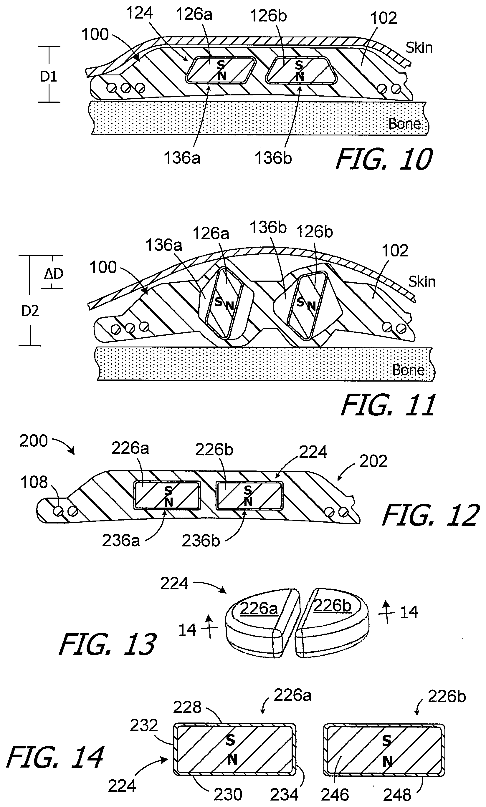
19. A system, comprising a cochlear implant as claimed in claim 11; a sound processor; and a headpiece, operably connected to the sound processor, including an antenna, and a headpiece magnet associated with the antenna that is attracted to the implant magnet.
Description
CROSS-REFERENCE TO RELATED APPLICATIONS
[0001] This application claims priority to U.S. Prov. App. Ser. No. 62/422,548, filed Nov. 15, 2016, which is incorporated herein by reference.
BACKGROUND
1. Field
[0002] The present disclosure relates generally to the implantable portion of implantable cochlear stimulation (or "ICS") systems.
2. Description of the Related Art
[0003] ICS systems are used to help the profoundly deaf perceive a sensation of sound by directly exciting the intact auditory nerve with controlled impulses of electrical current. Ambient sound pressure waves are picked up by an externally worn microphone and converted to electrical signals. The electrical signals, in turn, are processed by a sound processor, converted to a pulse sequence having varying pulse widths, rates and/or amplitudes, and transmitted to an implanted receiver circuit of the ICS system. The implanted receiver circuit is connected to an implantable electrode array that has been inserted into the cochlea of the inner ear, and electrical stimulation current is applied to varying electrode combinations to create a perception of sound. The electrode array may, alternatively, be directly inserted into the cochlear nerve without residing in the cochlea. A representative ICS system is disclosed in U.S. Pat. No. 5,824,022, which is entitled "Cochlear Stimulation System Employing Behind-The-Ear Sound processor With Remote Control" and incorporated herein by reference in its entirety. Examples of commercially available ICS sound processors include, but are not limited to, the Harmony.TM. BTE sound processor, the Naida.TM. CI Q Series sound processor and the Neptune.TM. body worn sound processor, which are available from Advanced Bionics.
[0004] As alluded to above, some ICS systems include an implantable cochlear stimulator (or "cochlear implant"), a sound processor unit (e.g., a body worn processor or behind-the-ear processor), and a microphone that is part of, or is in communication with, the sound processor unit. The cochlear implant communicates with the sound processor unit and, some ICS systems include a headpiece that is in communication with both the sound processor unit and the cochlear implant. The headpiece communicates with the cochlear implant by way of a transmitter (e.g., an antenna) on the headpiece and a receiver (e.g., an antenna) on the implant. Optimum communication is achieved when the transmitter and the receiver are aligned with one another. To that end, the headpiece and the cochlear implant may include respective positioning magnets that are attracted to one another, and that maintain the position of the headpiece transmitter over the implant receiver. The implant magnet may, for example, be located within a pocket in the cochlear implant housing.
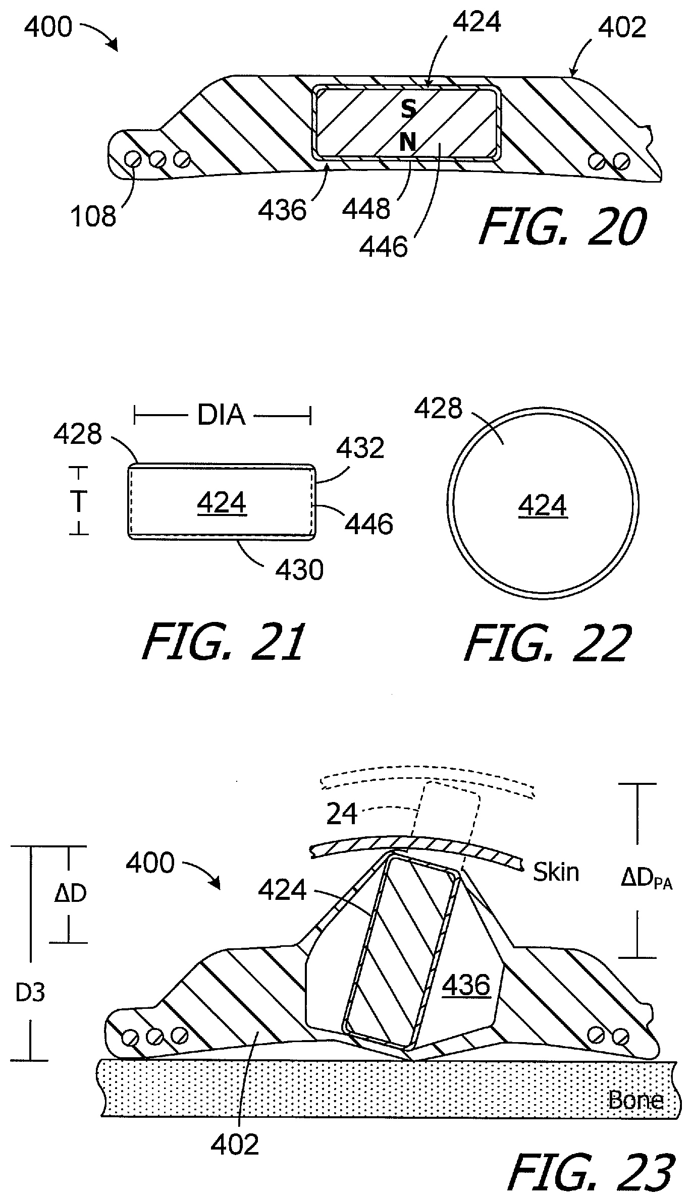
[0005] One example of a conventional cochlear implant (or "implantable cochlear stimulator") is the cochlear implant 10 illustrated in FIGS. 1 and 2. The cochlear implant 10 includes a flexible housing 12 formed from a silicone elastomer or other suitable material, a processor assembly 14, a cochlear lead 16 with a flexible body 18 and an electrode array 20, and an antenna 22 that may be used to receive data and power by way of an external antenna that is associated with, for example, a sound processor unit. A cylindrical positioning magnet 24, with north and south magnetic dipoles that are aligned in the axial direction of the disk, is located within the housing 12. The magnet 24 is used to maintain the position of a headpiece transmitter over the antenna 22. The magnet 24 is also relatively thin in conventional cochlear implants in order to provide a relatively thin implant.
[0006] There are some instances where it is necessary to remove the magnet from a conventional cochlear implant, and then reinsert the magnet, in situ, i.e., with the cochlear implant accessed by way of an incision in the skin. To that end, the positioning magnet 24 is carried within an internal magnet pocket 26 and can be inserted into, and removed from, the housing pocket by way of a magnet aperture 28 that extends through the housing top wall 30. The positioning magnet 24 has a diameter of 10.5 mm and a thickness of 2.2 mm. The magnet 22 is larger than the magnet aperture 28, i.e., the outer perimeter of the magnet is greater than the perimeter of the magnet aperture. The portion of the top wall 30 between the aperture 28 and the outer edge 32 of the magnet 24 forms a retainer 34 that, absent deformation of the aperture and retainer, prevents the magnet from coming out of the housing 12. During installation and removal, the aperture 28 and retainer 34 are stretched or otherwise deformed so that the magnet 24 can pass through the aperture 28.
[0007] The present inventors have determined that conventional cochlear implants are susceptible to improvement. For example, removal and replacement of the implant magnet by way of the aperture may be required because some conventional cochlear implants are not compatible with magnetic resonance imaging ("MRI") systems. As illustrated in FIG. 3, the implant magnet 24 produces a magnetic field M in a direction that is perpendicular to the patient's skin and parallel to the axis A. This magnetic field direction is not aligned with, and may be perpendicular to (as shown), the direction of the MRI magnetic field B. The misalignment of the interacting magnetic fields M and B is problematic for a number of reasons. The dominant MRI magnetic field B (typically 1.5 Tesla or more) may generate a significant amount of torque T on the implant magnet 24. The torque T may be sufficient to deform the retainer 34, dislodge the implant magnet 24 from the pocket 26 and reorient the magnet in the manner illustrated in FIG. 4. In some instances, the implant magnet 24 may rotate 180 degrees, thereby reversing the N-S orientation of the magnet. The present inventors have determined that such reorientation (and reversal) may also occur if there is no aperture in the flexible housing, and the magnet is embedded within a closed pocket, due to the softness of the material (e.g., silicone) used to form the housing.
[0008] Reorientation of the magnet 24 can place significant stress on the dermis (or "skin"), which cause significant pain. Prior to rotation (FIG. 3), the distance D1.sub.PA between the skull bone below the cochlear implant and the skin above the implant is relatively small, i.e., slightly greater than the thickness of the implant magnet 24. The distance between the bone and skin greatly increases to distance D2.sub.PA when the implant magnet 24 rotates to the orientation illustrated in FIG. 4. In fact, because the diameter of the magnet 24 is far greater than the thickness, the difference .DELTA.D.sub.PA is significantly greater than the original distance D1.sub.PA.
[0009] As alluded to above, magnet rotation may be avoided by surgically removing the magnet prior to the MRI procedure. However, in addition to the issues associated with the removal/replacement surgery, the presence of the magnet aperture 28 can lead to the formation of biofilm and can allow ingress of bacteria and microbes. Accordingly, the present inventors have determined that a solution which allows an MRI procedure to be performed without magnet removal/replacement surgery, thereby eliminating the need for the magnet aperture, would be desirable.
SUMMARY
[0010] A cochlear implant in accordance with one of the present inventions includes a cochlear lead, a housing, a magnet apparatus, located within the flexible housing, including a first partial disk shaped magnet member and a second partial disk shaped magnet member spaced apart from the first partial disk shaped magnet member, an antenna within the housing, and a stimulation processor. The present inventions also include systems with such a cochlear implant in combination with a headpiece, as well as systems with such a cochlear implant in combination with both a headpiece and a sound processor.
[0011] A cochlear implant in accordance with one of the present inventions includes a cochlear lead including a plurality of electrodes, a flexible housing including a magnet pocket, a top wall above the magnet pocket that does not include an opening into the magnet pocket, and a bottom wall below the magnet pocket that does not include an opening into the magnet pocket, a magnetic element, located within the magnet pocket, that defines a diameter, a thickness and the diameter to thickness ratio ("DtoT ratio") that is 2.5 or less, an antenna within the housing, and a stimulation processor. The present inventions also include systems with such a cochlear implant in combination with a headpiece, as well as systems with such a cochlear implant in combination with both a headpiece and a sound processor.
[0012] There are a number of advantages associated with such apparatus and systems. For example, when torque applied to the magnet apparatus by a strong magnetic field rotates the magnet apparatus, the increase in distance between the bone and skin (as well as the associated stress on the dermis and pain) will be far less than that associated with a conventional cochlear implant. As a result, surgical removal of the cochlear implant magnet prior to an MRI procedure, and then surgical replacement thereafter, is not required and the magnet aperture may be omitted.
[0013] The above described and many other features of the present inventions will become apparent as the inventions become better understood by reference to the following detailed description when considered in conjunction with the accompanying drawings.
BRIEF DESCRIPTION OF THE DRAWINGS
[0014] Detailed descriptions of the exemplary embodiments will be made with reference to the accompanying drawings.
[0015] FIG. 1 is a plan view of a conventional cochlear implant.
[0016] FIG. 2 is a section view taken along line 2-2 in FIG. 1.
[0017] FIG. 3 is a section view showing the conventional cochlear implant as an MRI magnetic field is being applied.
[0018] FIG. 4 is a section view showing the result of the application of the MRI magnetic field to the conventional cochlear implant.
[0019] FIG. 5 is a plan view of a cochlear implant in accordance with one embodiment of a present invention.
[0020] FIG. 6 is a section view taken along line 6-6 in FIG. 5.
[0021] FIG. 7 is a portion of FIG. 6 with the magnet apparatus removed.
[0022] FIG. 8 is a perspective view of a portion of the cochlear implant illustrated in FIG. 5.
[0023] FIG. 9 is a section view taken along line 9-9 in FIG. 8.
[0024] FIG. 10 is a section view of the cochlear implant illustrated in FIG. 5 prior to the application of a MRI magnetic field.
[0025] FIG. 11 is a section view showing the result of the application of the MRI magnetic field to the cochlear implant illustrated in FIG. 10.
[0026] FIG. 12 is a section view of a cochlear implant in accordance with one embodiment of a present invention.
[0027] FIG. 13 is a perspective view of a portion of the cochlear implant illustrated in FIG. 12.
[0028] FIG. 14 is a section view taken along line 14-14 in FIG. 13.
[0029] FIG. 15 is a partial section view of a cochlear implant in accordance with one embodiment of a present invention.
[0030] FIG. 16 is a side view of a portion of the cochlear implant illustrated in FIG. 15.
[0031] FIG. 17 is a perspective view of a portion of the cochlear implant illustrated in FIG. 15.
[0032] FIG. 18 is a side view of a portion of the cochlear implant illustrated in FIG. 15 in a partially rotated state.
[0033] FIG. 19 is a side view of a portion of the cochlear implant illustrated in FIG. 15 in a partially rotated state.
[0034] FIG. 20 is a section view of a cochlear implant in accordance with one embodiment of a present invention.
[0035] FIG. 21 is a side view of a portion of the cochlear implant illustrated in FIG. 20.
[0036] FIG. 22 is a plan view of a portion of the cochlear implant illustrated in
[0037] FIG. 20.
[0038] FIG. 23 is a section view showing the result of an application of a MRI magnetic field to the cochlear implant illustrated in FIG. 20.
[0039] FIG. 24 is a block diagram of a cochlear implant system in accordance with one embodiment of a present invention.
DETAILED DESCRIPTION OF THE EXEMPLARY EMBODIMENTS
[0040] The following is a detailed description of the best presently known modes of carrying out the inventions. This description is not to be taken in a limiting sense, but is made merely for the purpose of illustrating the general principles of the inventions.
[0041] One example of a cochlear implant (or "implantable cochlear stimulator") in accordance with the present inventions is the cochlear implant 100 illustrated in FIGS. 5-9. Referring first to FIG. 5, the exemplary cochlear implant 100 includes a resilient flexible housing 102 formed from a silicone elastomer or other suitable material (e.g., with a hardness from 50 to 70 Shore A), a processor assembly 104, a cochlear lead 106, and an antenna 108 that may be used to receive data and power by way of an external antenna that is associated with, for example, a sound processor unit. The cochlear lead 106 may include a flexible body 110, an electrode array 112 at one end of the flexible body 102, and a plurality of wires (not shown) that extend through the flexible body from the electrodes 114 (e.g., platinum electrodes) in the array 112 to the other end of the flexible body. The exemplary antenna 108 is a coil antenna with one or more loops (or "turns"), and three loops are shown in the illustrated embodiment. The exemplary processor assembly 104, which is connected to the electrode array 112 and antenna 108, includes a printed circuit board 116 with a stimulation processor 118 that is located within a hermetically sealed case 120. The stimulation processor 118 converts stimulation data into stimulation signals that stimulate the electrodes 114 of the electrode array 112. The hermetically sealed case 120 is located within a processor portion 122 of the housing 102. A positioning magnet apparatus 124 is located within an antenna portion 125 of the housing 102. The magnet apparatus 124, which is used to maintain the position of a headpiece transmitter over the antenna 108, is centered relative to the antenna 108.
[0042] Turning to FIGS. 6-9, the exemplary magnet apparatus 124 includes first and second magnet portions 126a and 126b which have complementary shapes that together define the overall shape of the magnet apparatus. In the illustrated implementation, the magnet apparatus 124 has an overall frustoconical shape with a circular (or substantially circular) bottom and a circular (or substantially circular) top. The first and second magnet portions 126a and 126b each have a partial disk shape and, to that end, have respective partial disk shaped top surfaces 128a and 128b, partial disk shaped bottom surfaces 130a and 130b, outer side surfaces 132a and 132b, and inner side surfaces 134a and 134b that face one another. As used herein, a "partial disk shaped" includes an arcuate edge of about 180 degrees (i.e., 180 degree.+-.5%) and a non-arcuate edge that extends from one end of the arcuate edge to the other. In a cross-section extending through the inner side surface 134a and 134b, the first magnet portion 126a has parallelogram shape (with rounded corners) and the second magnet portion 126b has a trapezoid shape (with rounded corners). The first and second magnet portions 126a and 126b also have the same N-S orientation.
[0043] The exemplary first and second magnet portions 126a and 126b are respectively located within magnet pockets 136a and 136b in the housing antenna portion 125 which, in their unstressed states, have sizes and shapes corresponding to those of the first and second magnet portions. In the illustrated implementation, the magnet portions 126a and 126b are embedded within the housing 102 such that, when the cochlear implant 100 is in its flat state (FIG. 6) without any rotation of the magnet portions 126a and 126b, the magnet portions are in contact with the resilient material that forms the housing and there are no gaps between the magnet portions and the inner surfaces of the magnet pockets. In particular, the magnet pockets 136a and 136b are surrounded by, and defined by, a bottom wall 138 that is located under the magnet pockets (in the illustrated orientation), a top wall 140 that is located above the magnet pockets (in the illustrated orientation), a side wall 142 that is lateral of, and extends around, the magnet pockets and a divider wall 144 that is located between the magnet pockets as well as between the magnet portions 126a and 126b. There are no openings in the bottom wall 138 or the top wall 140 for removal of the magnet apparatus 124. It should also be noted that the silicone elastomer (or other suitable resilient material) is stiff enough to maintain the magnet portions 126a and 126b in the illustrated orientation, in the absence of a strong external magnet filed, despite the N-N and S-S polar alignment of the magnet portions. The resilient material will, however, allow the magnet portions 126a and 126b to rotate in the manner described below with reference to FIGS. 10 and 11 when exposed to a MRI magnetic field. In some instances, a lubricious coating may be applied to the exterior of the magnet portions 126a and 126b to reduce the friction between magnet portions and the housing 102, thereby reducing torque. Suitable lubricious coatings include hydrophilic hydrogel and diamond-like carbon, both of which would significantly reduce friction and are biocompatible.
[0044] Although the present inventions are not so limited, the magnet portions 126a and 126b of the exemplary magnet apparatus 124 include respective magnetic elements 146a and 146b (FIG. 6) formed from a ferromagnetic material (e.g., N35 grade neodymium) and thin hermetically sealed housings 148a and 148b formed from, for example, biocompatible metals and/or plastics.
[0045] Such housing materials may, in some instances, be non-magnetic or paramagnetic. Suitable materials include, but are not limited to, titanium or titanium alloys, polyether ether ketone (PEEK), low-density polyethylene (LDPE), high-density polyethylene (HDPE) and polyamide. In particular, exemplary metals include commercially pure titanium (e.g., Grade 2) and the titanium alloy Ti-6Al-4V (Grade 5). With respect to the overall size of the magnet apparatus 124, the top diameter may be about 10.6 to 12.6 mm, the bottom diameter may be about 12.3 to 14.3 mm, and the thickness T (FIG. 9) may be about 2.2 to 3.0 mm. So configured, the width of the magnet portions 126a and 126b, i.e. the dimension perpendicular to the thickness T and to the axis of rotation AR, may be about 5.9 to 6.2 mm. The divider wall 144 adds about 1.0 mm to the diameters in the direction perpendicular to the wall.
[0046] Reorientation of the magnet portions 126a and 126b of the exemplary magnet apparatus 124 causes significantly less stress on the dermis and, accordingly, less pain than conventional implant magnets. Such rotation may be imparted by an MRI magnetic field. Prior to rotation when the cochlear implant is in the flat state (FIG. 10), the distance D1 between the skull bone below the cochlear implant and the skin above the implant is relatively small. This distance is approximately the same as distance D1.sub.PA (FIG. 3) of the conventional cochlear implant. The distance between the bone and skin increases only slightly by difference .DELTA.D to distance D2 when the implant magnet portions 126a and 126b rotate separately about their own axis of rotation AR (FIG. 9) to the orientation illustrated in FIG. 11, which shows the exemplary cochlear implant in a distended state. Such rotation also causes the portions of the housing 102 that define the magnet pockets 136a and 136b (as well as the pockets themselves) to stretch and distort. The resilience of the housing material will typically drive the implant magnet portions 126a and 126b to their flat-state orientations when the MRI magnetic field is removed. In some instances, however, the clinician may need to press on the skin over the magnet apparatus to drive the magnet portions back to their flat-state orientations.
[0047] It should be noted here that for a given rotational magnitude (e.g., about 75 degrees in FIGS. 4 and 11), the distances .DELTA.D and D2 (FIG. 11) associated with the implant magnet portions 126a and 126b are considerably less than the distances .DELTA.D.sub.PA and D2.sub.PA (FIG. 4) of the conventional cochlear implant magnet 24. This difference stems from the fact that the width W of the magnet portions 126a and 126b is far smaller than the diameter of the convention disk-shaped magnet 24.
[0048] The present magnet assembles (and associated magnet portions) are not limited to the configuration illustrated in FIGS. 5-11. To that end, the exemplary cochlear implant 200 illustrated in FIGS. 12-14 is identical to the implant 100 but for the magnet apparatus 224 and slightly differently shaped pockets 236a and 236b in housing 202. The magnet apparatus 224 has an overall cylindrical disk shape (as opposed to a frustoconical disk shape) defined by partial disk shaped magnet portions 226a and 226b. The magnet portions 226a and 226b are identical to one another and each include a partial disk shaped top surface 228, a partial disk shaped bottom surface 230, an outer side surface 232, and an inner side surface 234. In a cross-section perpendicular to the inner side surfaces 234, the magnet portions have a rectangular shape (with rounded corners). The magnet portions 226a and 226b also each include a magnetic element 246 and a thin hermetically sealed housing 248 formed from the materials described above. When exposed to an MRI magnetic field, the magnet apparatus 224 will behave in the manner described above with reference to FIGS. 10 and 11.
[0049] Turning to FIGS. 15-17, the exemplary cochlear implant 300 is similar to cochlear implant 200 and similar elements are represented by similar reference numerals. Here, however, the magnet apparatus 324 includes two partial disk shaped magnet portions 226a and 226b that are tethered to one another in a manner that allows magnet portions 226a and 226b to rotate, but limits the rotation to a predetermined amount. The housing 302 includes a single magnet pocket 336 to accommodate tethered arrangement. In the illustrated implementation, the magnet portions 226a and 226b are tethered to one another with a flexible strap 350. The flexible strap 350 includes end portions 352a and 352b, which are respectively secured to the magnet portions 226a and 226b, and an intermediate portion 354 that is not secured to either magnet portion. For example, the end portions 352a and 352b may be secured to the bottom surfaces 230 of the magnet portions 226a and 226b with an adhesive or other suitable instrumentality. The end portions 352a and 352b are not secured to any other surfaces. In other implementations, the end portions 352a and 352b may be secured to more than one surface of one or both of the magnet portions 226a and 226b and/or may be secured to different surfaces (or sets of surfaces) on the magnet portions 226a and 226b. Suitable materials for the flexible strap 250 include, but are not limited to, a nylon cloth strap or Kapton.RTM. (polyimide film) tape, including those with reinforcing fibers (e.g., Kevlar.RTM. or polyethylene fibers). It should also be noted here that the housing 302 may be formed in two steps, with a bottom cap overmolded onto the remainder of the housing (and formed from the same material as the remainder of the housing) after the tethered magnet portions 226a and 226b have been inserted into the pocket 336.
[0050] Although the amount of allowed rotation may vary from one implementation to another, the flexible strap 350 in the illustrated implementation allows the magnet portions 226a and 226b to rotate up to approximately 135 degrees form the flat-state orientation illustrated in FIGS. 15-17 in response to the presence of an MRI magnetic field. The magnet portions 226a and 226b may, for example, rotate to the orientation illustrated in FIG. 18 in some instances. Rotation beyond the orientation illustrated in FIG. 19 is, however, prevented by the strap 250. As a result, an MRI magnetic field will not cause the N-S orientations of the magnet portions 226a and 226b to be completely reversed.
[0051] Referring to FIGS. 20-23, the stress on the skin (and associated pain) may also be reduced by employing particular magnet diameter to thickness ratios ("D/T ratios"). To that end, the exemplary cochlear implant 400 illustrated in FIG. 20 is similar to cochlear implant 300 and similar elements are represented by similar reference numerals. Here, however, the magnet apparatus 424 is a unitary structure which does not include a pair of magnet portions. The magnet apparatus 424 has a cylindrical disk shape and includes a circular top surface 428, a circular bottom surface 430, and an outer side surface 432, and is formed from a magnetic element 446 and a thin hermetically sealed housing 448 that covers the outer surface of, and has the same overall shape as, the magnetic element. In a cross-section through the diameter, the magnet apparatus 424 has a rectangular shape (with rounded corners).
[0052] The exemplary magnetic element 446 may have a DtoT ratio of 2.5 or less. To that end, the exemplary magnetic element 446 has a diameter DIA of 7.1 mm, a thickness T of 2.8 mm, and a DtoT ratio of 2.5. In another exemplary embodiment, the magnetic element may have a diameter DIA of 6.5 mm, a thickness T of 3.5 mm, and a DtoT ratio of 1.9. In other embodiments, the DtoT ratio may range from 2.5 to 1.9, with magnetic element diameters of 7.1 or less, and magnet thicknesses of 2.8 or more. The dimensions magnet apparatus also include the thin housing 448, which adds about 0.2 to 0.3 mm to the diameters and thicknesses discussed above. For purposes of comparison, the conventional magnet 24 illustrated in FIGS. 1-4, which has a diameter of 10.5 mm and a thickness of 2.2 mm, has a DtoT ratio of 4.8. Suitable material for the magnetic element 446 includes N52 grade neodymium, and suitable materials for the housing 448 include the housing materials described above.
[0053] Referring to FIG. 23, the magnet apparatus 424 will rotate in a manner similar to the conventional magnet 24 when exposed to an MRI magnetic field. However, the distances .DELTA.D and D3 associated with the magnet apparatus 424 are considerably less than the distances .DELTA.D.sub.PA and D2.sub.PA of the conventional cochlear implant. This difference stems from the fact that the diameter of the magnet apparatus 424 is smaller than the diameter of the convention disk-shaped magnet 24. As a result, reorientation of the magnet apparatus 424 causes significantly less stress on the dermis and, accordingly, less pain than the conventional implant magnet 24.
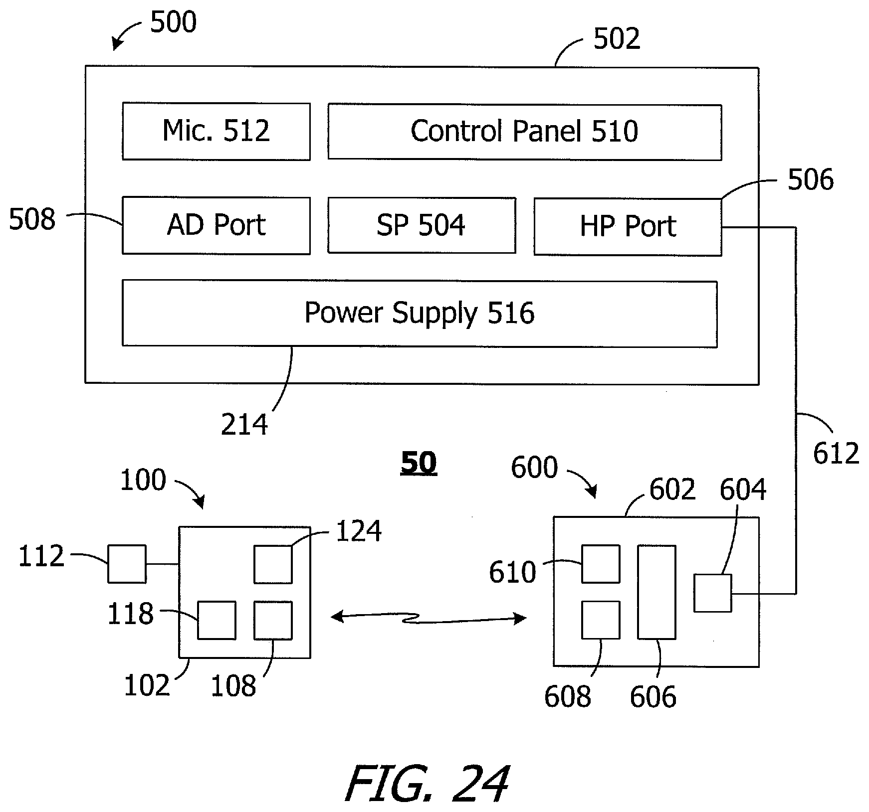
[0054] As illustrated in FIG. 24, the exemplary cochlear implant system 50 includes the cochlear implant 100 (or 200 or 300 or 400), a sound processor, such as the illustrated body worn sound processor 200 or a behind-the-ear sound processor, and a headpiece 300.
[0055] The exemplary body worn sound processor 500 in the exemplary ICS system 50 includes a housing 502 in which and/or on which various components are supported. Such components may include, but are not limited to, sound processor circuitry 504, a headpiece port 506, an auxiliary device port 508 for an auxiliary device such as a mobile phone or a music player, a control panel 510, one or microphones 512, and a power supply receptacle 514 for a removable battery or other removable power supply 516 (e.g., rechargeable and disposable batteries or other electrochemical cells). The sound processor circuitry 504 converts electrical signals from the microphone 512 into stimulation data. The exemplary headpiece 600 includes a housing 602 and various components, e.g., a RF connector 604, a microphone 606, an antenna (or other transmitter) 608 and a positioning magnet apparatus 610, that are carried by the housing. The magnet apparatus 610 may consist of a single magnet or may consist of one or more magnets and a shim. The headpiece 600 may be connected to the sound processor headpiece port 506 by a cable 612. The positioning magnet apparatus 610 is attracted to the magnet apparatus 124 of the cochlear stimulator 100, thereby aligning the antenna 608 with the antenna 108. The stimulation data and, in many instances power, is supplied to the headpiece 600. The headpiece 600 transcutaneously transmits the stimulation data, and in many instances power, to the cochlear implant 100 by way of a wireless link between the antennas. The stimulation processor 118 converts the stimulation data into stimulation signals that stimulate the electrodes 114 of the electrode array 112.
[0056] In at least some implementations, the cable 612 will be configured for forward telemetry and power signals at 49 MHz and back telemetry signals at 10.7 MHz. It should be noted that, in other implementations, communication between a sound processor and a headpiece and/or auxiliary device may be accomplished through wireless communication techniques. Additionally, given the presence of the microphone(s) 512 on the sound processor 500, the microphone 606 may be also be omitted in some instances. The functionality of the sound processor 500 and headpiece 600 may also be combined into a single head wearable sound processor. Examples of head wearable sound processors are illustrated and described in U.S. Pat. Nos. 8,811,643 and 8,983,102, which are incorporated herein by reference in their entirety.
[0057] Although the inventions disclosed herein have been described in terms of the preferred embodiments above, numerous modifications and/or additions to the above-described preferred embodiments would be readily apparent to one skilled in the art. By way of example, but not limitation, the inventions include any combination of the elements from the various species and embodiments disclosed in the specification that are not already described. It is intended that the scope of the present inventions extend to all such modifications and/or additions and that the scope of the present inventions is limited solely by the claims set forth below.
* * * * *
D00000
D00001
D00002
D00003
D00004
D00005
D00006
D00007
XML
uspto.report is an independent third-party trademark research tool that is not affiliated, endorsed, or sponsored by the United States Patent and Trademark Office (USPTO) or any other governmental organization. The information provided by uspto.report is based on publicly available data at the time of writing and is intended for informational purposes only.
While we strive to provide accurate and up-to-date information, we do not guarantee the accuracy, completeness, reliability, or suitability of the information displayed on this site. The use of this site is at your own risk. Any reliance you place on such information is therefore strictly at your own risk.
All official trademark data, including owner information, should be verified by visiting the official USPTO website at www.uspto.gov. This site is not intended to replace professional legal advice and should not be used as a substitute for consulting with a legal professional who is knowledgeable about trademark law.