Tibial Prosthesis With Tibial Bearing Component Securing Feature
Byrd; Brian D. ; et al.
U.S. patent application number 16/849394 was filed with the patent office on 2020-07-30 for tibial prosthesis with tibial bearing component securing feature. The applicant listed for this patent is Zimmer, Inc.. Invention is credited to Jeff Blaylock, Brian D. Byrd, Vanessa Croll, Abraham P. Habegger, Kathleen Macke, Dwight T. Todd, James D. Wernle.
| Application Number | 20200237518 16/849394 |
| Document ID | 20200237518 / US20200237518 |
| Family ID | 1000004754430 |
| Filed Date | 2020-07-30 |
| Patent Application | download [pdf] |


View All Diagrams
| United States Patent Application | 20200237518 |
| Kind Code | A1 |
| Byrd; Brian D. ; et al. | July 30, 2020 |
TIBIAL PROSTHESIS WITH TIBIAL BEARING COMPONENT SECURING FEATURE
Abstract
According to one example, a tibial prosthesis that can include a tibial bearing component, tibial baseplate, an insert and a fastener. The tibial bearing component can have medial and lateral proximal articular surfaces and an opposing distal surface. The tibial bearing component can define at least one recess therein with the recess having an opening at a periphery of the tibial bearing component. The tibial baseplate can be coupled to the tibial bearing component on the proximal surface thereof and having a distal surface configured to be disposed on a resected proximal surface of a tibia. The insert can be configured to be disposed within the recess and can engage the tibial baseplate and the tibial bearing component. The fastener can be insertable into the tibial bearing component and can be configured to retain the insert to the tibial baseplate.
| Inventors: | Byrd; Brian D.; (North Webster, IN) ; Macke; Kathleen; (Warsaw, IN) ; Todd; Dwight T.; (Fort Wayne, IN) ; Wernle; James D.; (Warsaw, IN) ; Croll; Vanessa; (Warsaw, IN) ; Blaylock; Jeff; (Fort Wayne, IN) ; Habegger; Abraham P.; (Warsaw, IN) | ||||||||||
| Applicant: |
|
||||||||||
|---|---|---|---|---|---|---|---|---|---|---|---|
| Family ID: | 1000004754430 | ||||||||||
| Appl. No.: | 16/849394 | ||||||||||
| Filed: | April 15, 2020 |
Related U.S. Patent Documents
| Application Number | Filing Date | Patent Number | ||
|---|---|---|---|---|
| 15915886 | Mar 8, 2018 | 10675153 | ||
| 16849394 | ||||
| 62469924 | Mar 10, 2017 | |||
| Current U.S. Class: | 1/1 |
| Current CPC Class: | A61F 2002/30476 20130101; A61F 2/3886 20130101; A61F 2002/30433 20130101; A61F 2002/30401 20130101; A61F 2/389 20130101 |
| International Class: | A61F 2/38 20060101 A61F002/38 |
Claims
1. A tibial prosthesis for a knee arthroplasty comprising: a tibial bearing component having medial and lateral proximal articular surfaces and an opposing distal surface, wherein the tibial bearing component defines at least one recess therein with the recess having an opening at a periphery of the tibial bearing component; a tibial baseplate coupled to the tibial bearing component on a proximal surface thereof and having a distal surface configured to be disposed on a resected proximal surface of a tibia; an insert configured to be disposed within the recess and engage the tibial baseplate and the tibial bearing component; and a fastener retaining the insert to the tibial baseplate.
2. The tibial prosthesis of claim 1, wherein the tibial bearing component comprises a posterior-stabilized tibial bearing component with a spine disposed between the medial and lateral proximal articular surfaces.
3. The tibial prosthesis of claim 1, wherein the insert comprises: a body having an aperture defined thereby, the aperture receives a head of the fastener; a first foot connected to the body and extending distal therefrom, the first foot having a first side surface engaging the tibial baseplate; and a second foot connected to the body and extending distal therefrom, the second foot spaced from the first foot and having a second side surface engaging the tibial baseplate.
4. The tibial prosthesis of claim 3, wherein the insert further comprises a tab extending proximally from the body, the tab engaging the tibial bearing component to retain the insert within the tibial bearing component.
5. The tibial prosthesis of claim 3, wherein the body includes a first wing that extends lateral of the first foot and a second wing that extends medial of the second foot.
6. The tibial prosthesis of claim 3, wherein the head of the fastener and the aperture share a similar curvature such the fastener is self-centering within the insert.
7. The tibial prosthesis of claim 1, wherein the opening is at an anterior portion of the periphery of the tibial bearing component and the insert is disposed in the recess such that substantially an entirety of the insert is disposed anterior of the fastener.
8. The tibial prosthesis of claim 1, wherein the tibial baseplate includes a rail extending from the proximal surface along a periphery thereof, wherein the rail has a gap in a region of the recess, and wherein with the insert disposed in the recess, at least a portion thereof extends into the gap and engages the rail to limit micro-motion of the tibial bearing component.
9. The tibial prosthesis of claim 1, further comprising a second aperture formed in the tibial bearing component and extending from between the medial and lateral proximal articular surfaces to communicate with the recess, wherein the second aperture is configured to receive at least a portion of the fastener, and wherein the second aperture is angled relative to a proximal-distal axis of the tibial bearing component such that second aperture extends both proximal-distal and anterior-posterior.
10. A system for use in a knee arthroplasty comprising: a tibial bearing component having medial and lateral proximal articular surfaces and an opposing distal surface, wherein the tibial bearing component defines at least one recess therein with the recess having an opening at a periphery of the tibial bearing component; a tibial baseplate configured to receive the tibial bearing component on a proximal surface thereof and having a distal surface configured to be disposed on a resected proximal surface of a tibia; an insert disposable through the opening and into the recess, the insert configure to engage the tibial baseplate and the tibial bearing component when the insert, the tibial baseplate and the tibial bearing component are assembled together; and a fastener insertable into the tibial bearing component and configured to retain the insert to the tibial baseplate.
11. The system of claim 10, wherein the tibial bearing component comprises a posterior-stabilized tibial bearing component with a spine disposed between the medial and lateral proximal articular surfaces, and wherein the fastener is insertable into an anterior portion of the spine.
12. The system of claim 10, wherein the insert comprises: a body having an aperture defined thereby, the aperture configured to receive a head of the fastener; a first foot extending generally distal from the body and having a first side surface engaging the tibial baseplate; and a second foot extending generally distal from the body and spaced from the first foot, the second foot having a second side surface engaging the tibial baseplate.
13. The system of claim 12, wherein the insert further comprises a tab extending proximally from the body and configured to engage the tibial bearing component to retain the insert within the tibial bearing component.
14. The system of claim 12, wherein the body includes a first wing that extends lateral of the first foot and a second wing that extends medial of the second foot.
15. The system of claim 12, wherein the head of the fastener and the aperture share a similar curvature such the fastener is self-centering within the insert.
16. The system of claim 10, wherein the opening is at an anterior portion of the periphery of the tibial bearing component and the insert is disposed in the recess when assembled such that substantially an entirety of the insert is disposed anterior of the fastener.
17. The system of claim 10, wherein the tibial baseplate includes a rail extending from the proximal surface along a periphery thereof, wherein the rail has a gap in a region of the recess and forms a part of the opening, and wherein with the insert disposed in the gap the insert is configured to engage the rail to limit micro-motion of the tibial bearing component.
18. The system of claim 10, further comprising a second aperture formed in the tibial bearing component and extending from the medial and lateral proximal articular surfaces to communicate with the recess, wherein the second aperture is configured to receive at least a portion of the fastener, and wherein the second aperture is angled relative to a proximal-distal axis of the tibial bearing component such that second aperture extends both proximal-distal and anterior-posterior.
19. A method of assembling a tibial prosthesis for a knee arthroplasty, the method comprising: passing an insert through a peripheral opening and into a recess formed in a tibial bearing component; engaging a portion of the insert with the tibial bearing component while having wings of the insert received in corresponding grooves that are part of the recess; engaging the tibial bearing component with a tibial baseplate; and fastening the insert to the tibial baseplate.
20. The method of claim 19, wherein fastening the insert to the tibial baseplate includes passing a fastener through a proximal surface region located between medial and lateral proximal articular surfaces of the tibial bearing component.
Description
CLAIM OF PRIORITY
[0001] This application is a continuation of U.S. patent application Ser. No. 15/915,886, filed Mar. 8, 2018, which claims the benefit of U.S. Provisional Patent Application Ser. No. 62/469,924, filed on Mar. 10, 2017, the benefit of priority of each of which is claimed hereby, and each of which is incorporated by reference herein in its entirety.
FIELD
[0002] The present subject matter relates to orthopedic prostheses and, more particularly, to prostheses, systems and methods used in knee arthroplasties including revision knee arthroplasties.
BACKGROUND
[0003] Orthopedic procedures and prostheses are commonly utilized to repair and/or replace damaged bone and tissue in the human body. For example, a knee arthroplasty can be used to restore natural knee function by repairing damaged or diseased articular surfaces of the femur and/or tibia. An incision is made into the knee joint to expose the bones comprising the joint. Cut guides are used to guide the removal of the articular surfaces that are to be replaced. Prostheses are used to replicate the articular surfaces. Knee prostheses can include a femoral component implanted on the distal end of the femur, which articulates with a tibial bearing component and a tibial component implanted on the proximal end of a tibia to replicate the function of a healthy natural knee. Various types of arthroplasties are known including a total knee arthroplasty, where all of the articulating compartments of the joint are repaired with prosthetic components.
OVERVIEW
[0004] This disclosure pertains generally to tibial prostheses, systems, and methods for a knee arthroplasty including a revision knee arthroplasty, The present inventors have recognized, among other things, that a degree of micro-motion experienced by a tibial bearing component relative to a tibial baseplate can be reduced by providing an additional lockdown feature(s). Reduction of micro-motion can provide better overall durability for the tibial beating component when assembled with the tibial baseplate. Furthermore, present inventors have recognized that with additional lockdown features, a greater rigidity and torsional strength can be provided to the tibial bearing component. As such, metal reinforcement need not be provided to a spine of the tibial bearing component. Thus, the weight of the tibial bearing component can be reduced.
[0005] As used herein, "micro-motion" refers to the small motions that may exist between prosthesis components, such as between the tibial baseplate and the tibial bearing component, respectively, upon application of force. Such small motions may occur as a result of material deformation in one or both of the interacting components, or may result from slight spaces or clearances therebetween, for example. Micro-motion is distinguished from "mobile bearing" applications, which experience relatively larger motions as the tibial bearing component articulates with respect to the tibial baseplate (such as by sliding or rotating) along a desired motion path.
[0006] As used herein, a "fixed bearing" tibial prosthesis is a prosthesis in which the tibial bearing component is seated atop the tibial baseplate in a final, locked, and secured position. In this secured position, lift-off of the tibial bearing component from the tibial baseplate as well as transverse movement of the tibial bearing component relative to the tibial baseplate is prevented during natural articulation of the knee. Some micro-motion may exist between the tibial bearing component and tibial baseplate in a fixed bearing prosthesis.
[0007] To further illustrate the apparatuses and systems disclosed herein, the following non-limiting examples are provided:
[0008] Example 1 is a tibial prosthesis for a knee arthroplasty that can optionally comprise: a tibial bearing component having medial and lateral proximal articular surfaces and an opposing distal surface, wherein the tibial bearing component defines at least one recess therein with the recess having an opening at a periphery of the tibial bearing component; a tibial baseplate coupled to the tibial beating component on a proximal surface thereof and having a distal surface configured to be disposed on a resected proximal surface of a tibia; an insert configured to be disposed within the recess and engage the tibial baseplate and the tibial bearing component; and a fastener retaining the insert to the tibial baseplate.
[0009] In Example 2, the subject matter of Example 1 can optionally include wherein the tibial bearing component comprises a posterior-stabilized tibial bearing component with a spine disposed between the medial and lateral proximal articular surfaces.
[0010] in Example 3, the subject matter of any one or more of Examples 1-2 can optionally include wherein the insert comprises: a body having an aperture defined thereby, the aperture receives a head of the fastener; a first foot connected to the body and extending distal therefrom, the first foot having a first side surface engaging the tibial baseplate; and a second foot connected to the body and extending distal therefrom, the second foot spaced from the first foot and having a second side surface engaging the tibial baseplate.
[0011] In Example 4, the subject matter of Example 3 can optionally include wherein the insert further comprises a tab extending proximally from the body, the tab engaging the tibial bearing component to retain the insert within the tibial bearing component.
[0012] In Example 5, the subject matter of any one or more of Examples 3-4 can optionally include wherein the body includes a first wing that extends lateral of the first foot and a second wing that extends medial of the second foot.
[0013] in Example 6, the subject matter of any one or more of Examples 3-5 can optionally include wherein the head of the fastener and the aperture share a similar curvature such the fastener is self-centering within the insert.
[0014] In Example 7, the subject matter of any one or more of Examples 1-6 can optionally include wherein the opening is at an anterior portion of the periphery of the tibial bearing component and the insert is disposed in the recess such that substantially an entirety of the insert is disposed anterior of the fastener.
[0015] In Example 8, the subject matter of any one or more of Examples 1-7 can optionally include wherein the tibial baseplate includes a rail extending from the proximal surface along a periphery thereof, wherein the rail has a gap in a region of the recess, and wherein with the insert disposed in the recess, at least a portion thereof extends into the gap and engages the rail to limit micro-motion of the tibial bearing component.
[0016] In Example 9, the subject matter of any one or more of Examples 1-8 can optionally include a second aperture formed in the tibial bearing component and extending from between the medial and lateral proximal articular surfaces to communicate with the recess, wherein the second aperture is configured to receive at least a portion of the fastener, and wherein the second aperture is angled relative to a proximal-distal axis of the tibial bearing component such that second aperture extends both proximal-distal and anterior-posterior.
[0017] Example 10 is a system for use in a knee arthroplasty can optionally comprise: a tibial bearing component having medial and lateral proximal articular surfaces and an opposing distal surface, wherein the tibial bearing component defines at least one recess therein with the recess having an opening at a periphery of the tibial bearing component; a tibial baseplate configured to receive the tibial bearing component on a proximal surface thereof and having a distal surface configured to be disposed on a resected proximal surface of a tibia; an insert disposable through the opening and into the recess, the insert configure to engage the tibial baseplate and the tibial bearing component when the insert, the tibial baseplate and the tibial bearing component are assembled together; and a fastener insertable into the tibial bearing component and configured to retain the insert to the tibial baseplate.
[0018] In Example 11, the subject matter of Example 10 can optionally include wherein the tibial bearing component comprises a posterior-stabilized tibial bearing component with a spine disposed between the medial and lateral proximal articular surfaces, and wherein the fastener is insertable into an anterior portion of the spine.
[0019] In Example 12, the subject matter of any one or more of Examples 10-11 can optionally include wherein the insert comprises: a body having an aperture defined thereby, the aperture configured to receive a head of the fastener, a first foot extending generally distal from the body and having a first side surface engaging the tibial baseplate; and a second foot extending generally distal from the body and spaced from the first foot, the second foot having a second side surface engaging the tibial baseplate.
[0020] In Example 13, the subject matter of Example 12 can optionally include wherein the insert further comprises a tab extending proximally from the body and configured to engage the tibial bearing component to retain the insert within the tibial bearing component.
[0021] In Example 14, the subject matter of any one or more of Examples 12-13 can optionally include wherein the body includes a first wing that extends lateral of the first foot and a second wing that extends medial of the second foot.
[0022] In Example 15, the subject matter of any one or more of Examples 12-14 can optionally include wherein the head of the fastener and the aperture share a similar curvature such the fastener is self-centering within the insert.
[0023] In Example 16, the subject matter of any one or more of Examples 10-15 can optionally include wherein the opening is at an anterior portion of the periphery of the tibial bearing component and the insert is disposed in the recess when assembled such that substantially an entirety of the insert is disposed anterior of the fastener.
[0024] In Example 17, the subject matter of any one or more of Examples 10-16 can optionally include wherein the tibial baseplate includes a rail extending from the proximal surface along a periphery thereof, wherein the rail has a gap in a region of the recess and forms a part of the opening, and wherein with the insert disposed in the gap the insert is configured to engage the rail to limit micro-motion of the tibial bearing component.
[0025] In Example 18, the subject matter of any one or more of Examples 10-17 can optionally include a second aperture formed in the tibial bearing component and extending from the medial and lateral proximal articular surfaces to communicate with the recess, wherein the second aperture is configured to receive at least a portion of the fastener, and wherein the second aperture is angled relative to a proximal-distal axis of the tibial bearing component such that second aperture extends both proximal-distal and anterior-posterior.
[0026] Example 19 is a method of assembling a tibial prosthesis for a knee arthroplasty, the method can optionally comprise: passing an insert through a peripheral opening and into a recess formed in a tibial bearing component; engaging a portion of the insert with the tibial bearing component while having wings of the insert received in corresponding grooves that are part of the recess; engaging the tibial bearing component with a tibial baseplate; and fastening the insert to the tibial baseplate.
[0027] In Example 20, the subject matter of Example 19 can optionally include wherein fastening the insert to the tibial baseplate includes passing a fastener through a proximal surface region located between medial and lateral proximal articular surfaces of the tibial bearing component.
[0028] In Example 21, the subject matter of any one or more of Examples 19-20 can optionally include engaging a first foot of the insert with a first portion of a rail of the tibial baseplate and engaging a second foot of the insert with a second portion of the rail of the tibial baseplate.
BRIEF DESCRIPTION OF THE DRAWINGS
[0029] In the drawings, which are not necessarily drawn to scale, like numerals can describe similar components in different views. Like numerals having different letter suffixes can represent different instances of similar components. The drawings illustrate generally, by way of example, but not by way of limitation, various examples discussed in the present document.
[0030] FIG. 1A shows a perspective view of a prosthesis assembly including a femoral component, tibial bearing component and tibial baseplate according to an example of the present application.
[0031] FIG. 1B show a cross-sectional view of the prosthesis assembly of FIG. 1A showing an insert and a fastener in addition to the aforementioned femoral component, tibial bearing component and tibial baseplate according to an example of the present application.
[0032] FIG. 2 shows a cross-sectional view of another example of the prosthesis assembly but with the femoral component moved to an extension position rather than the 135.degree. flexion position previously illustrated according to an example of the present application.
[0033] FIGS. 3A-3D illustrate a method of assembly for a tibial prosthesis according to an example of the present application.
[0034] FIG. 4 shows the tibial prosthesis after having undergone the assembly previously illustrated in FIG. 3.
[0035] FIG. 4A shows an enlargement of a portion of the tibial prosthesis further illustrating the insert engaging portions of the tibial baseplate according to an example of the present application.
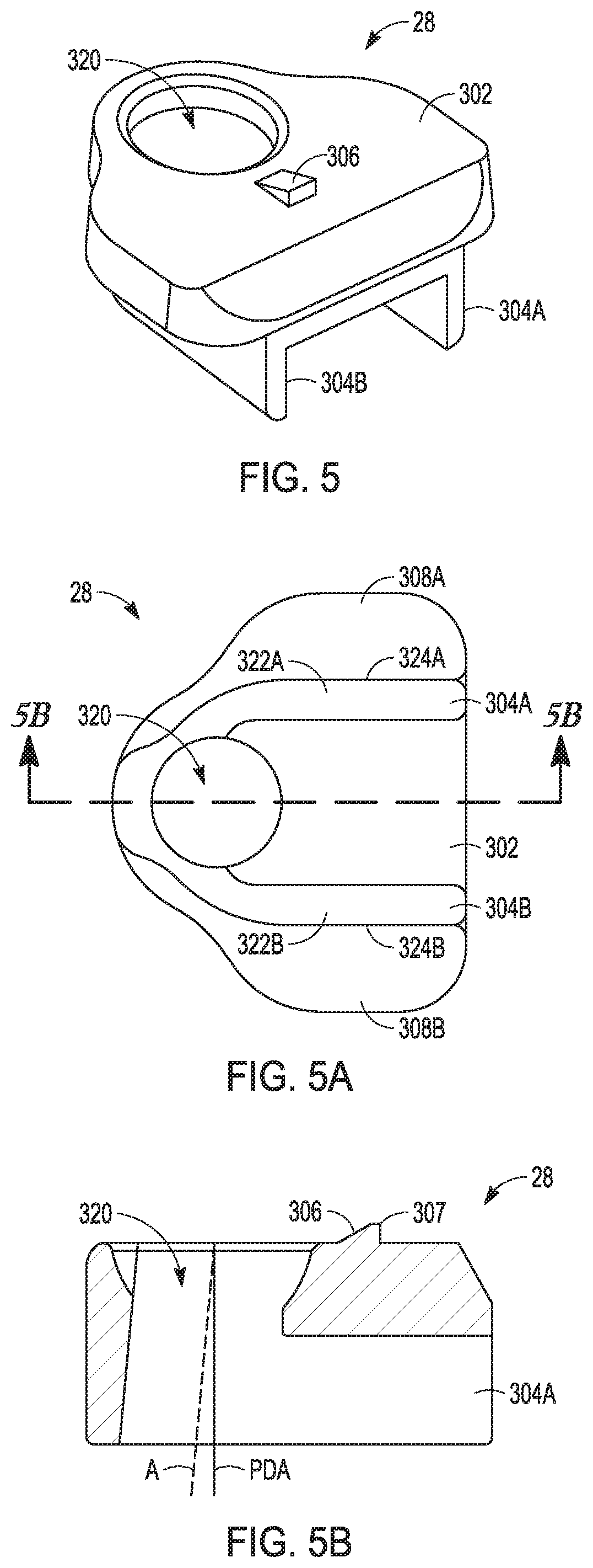
[0036] FIG. 5 show a perspective view of the insert according to an example of the present application.
[0037] FIG. 5A shows a plan view of a distal portion of insert including first and second feet and an aperture according to an example of the present application.
[0038] FIG. 5B is a cross-sectional view of the insert along line 5B-5B of FIG. 5A.
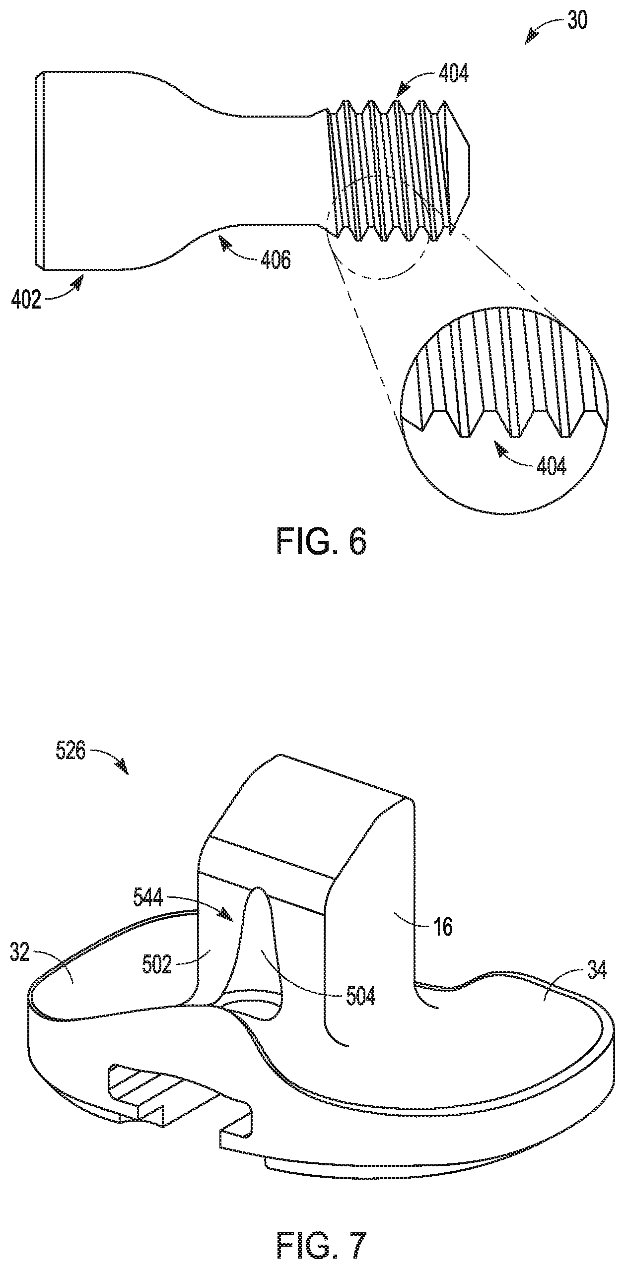
[0039] FIG. 6 is a plan view of the fastener according to an example of the present application.
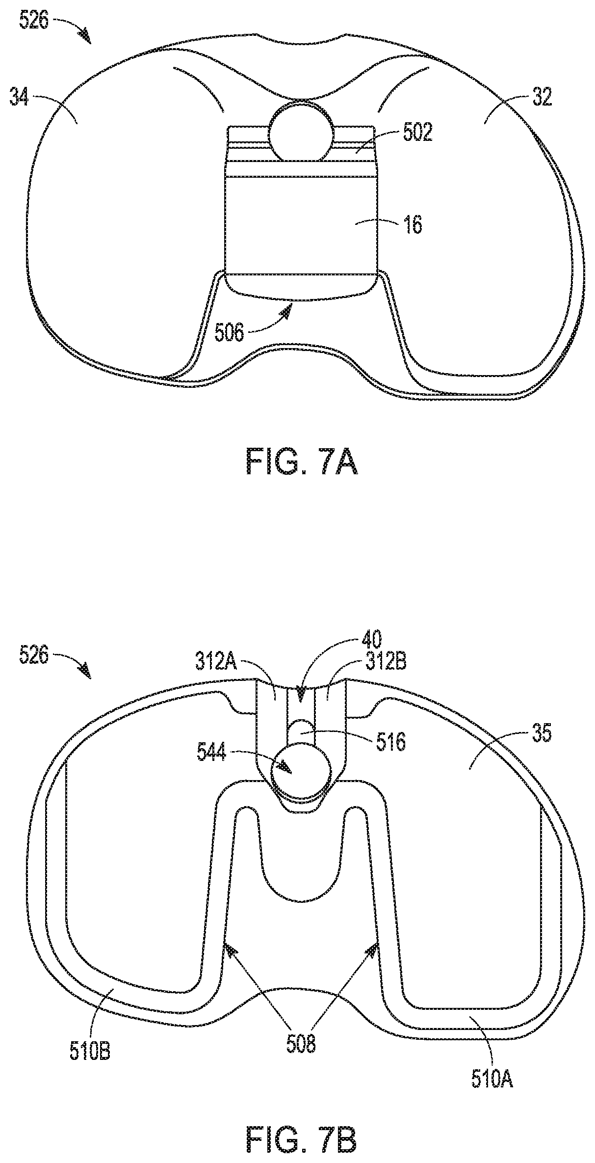
[0040] FIGS. 7-7C show the tibial bearing component from various perspectives according to an example of the present application.
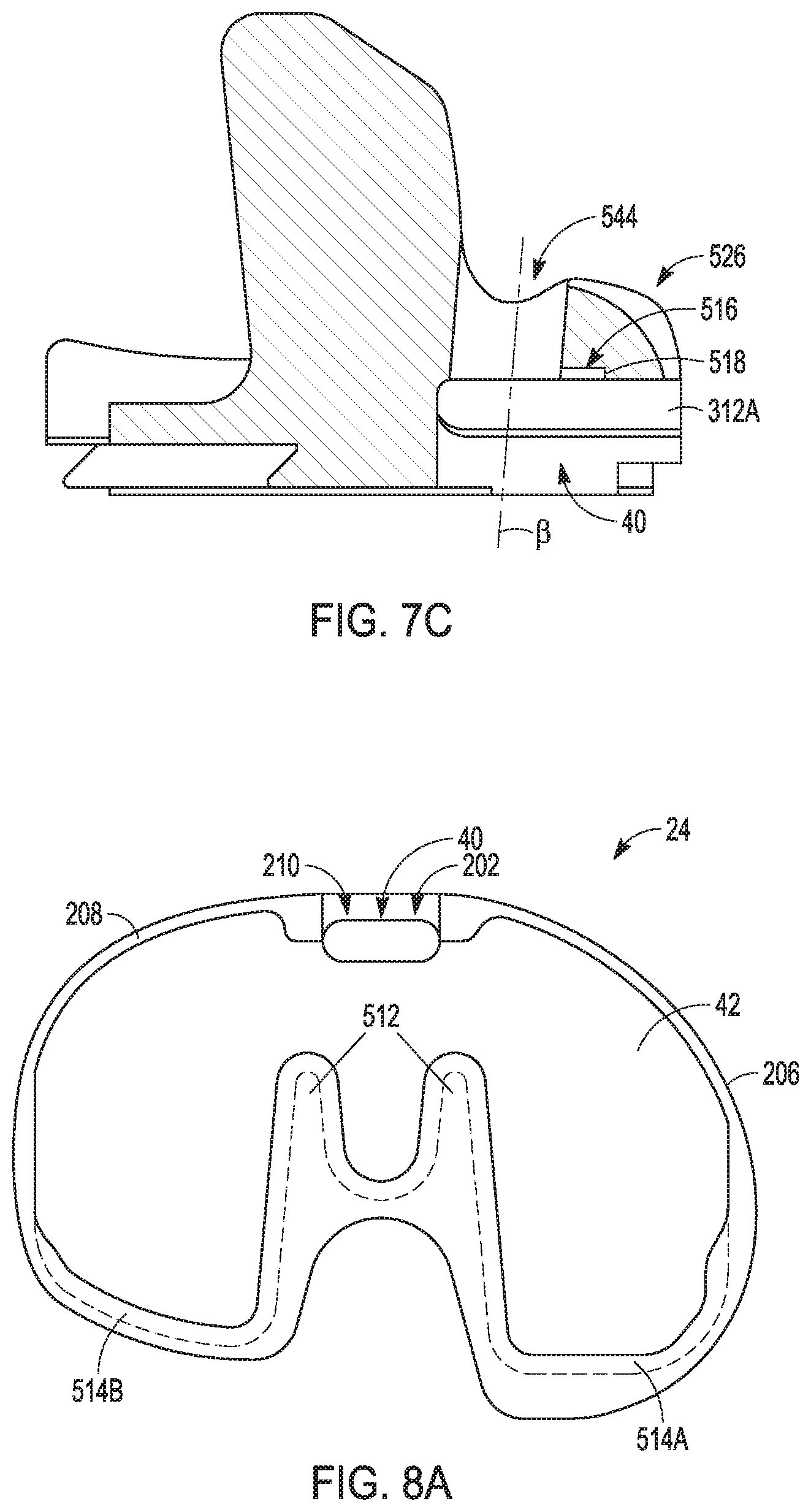
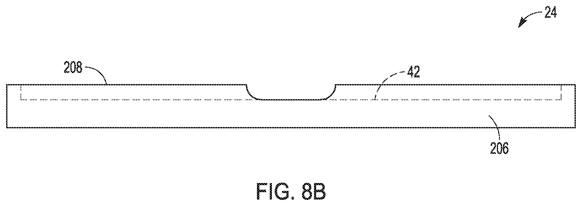
[0041] FIGS. 8A and 8B show the tibial baseplate from various perspectives according to an example of the present application.
DETAIL ED DESCRIPTION
[0042] The present application relates tibial prostheses, systems, and methods. The systems, for example, can include a tibial bearing component, a tibial baseplate, an insert and a fastener.
[0043] The present application relates a prosthesis assembly that can be used in a knee arthroplasty and/or as part of a later knee revision surgery. As described herein, the prosthesis assembly can include tibial prosthesis and a femoral prosthesis. This application focuses on aspects of the tibial prosthesis, which can include a tibial baseplate, a tibial bearing component, an insert and a fastener. As discussed previously, the tibial prosthesis can be configured to reduce micro-motion between the tibial bearing component and the tibial baseplate. This can improve the durability of the tibial prosthesis. Additional features and benefits of the various examples provided herein will be discussed and/or will be apparent to one of ordinary skill in the art.
[0044] As used herein, the terms "proximal" and "distal" should be given their generally understood anatomical interpretation. The term "proximal" refers to a direction generally toward the torso of a patient, and "distal" refers to the opposite direction of proximal, i.e., away from the torso of a patient. It should be understood that the use of the terms "proximal" and "distal" should be interpreted as though the patient were standing with the knee joint in extension despite the apparatuses described herein generally being used with the knee joint in flexion. The intent is to differentiate the terms "proximal" and "distal" from the terms "anterior" and "posterior". As used herein, the terms "anterior" and "posterior" should be given their generally understood anatomical interpretation. Thus, "posterior" refers to a rear of the patient, e.g., a back of the knee. Similarly, "anterior" refers to a front of the patient, e.g., a front of the knee. Thus, "posterior" refers to the opposite direction of "anterior", Similarly, the term "lateral" refers to the opposite direction of "medial".
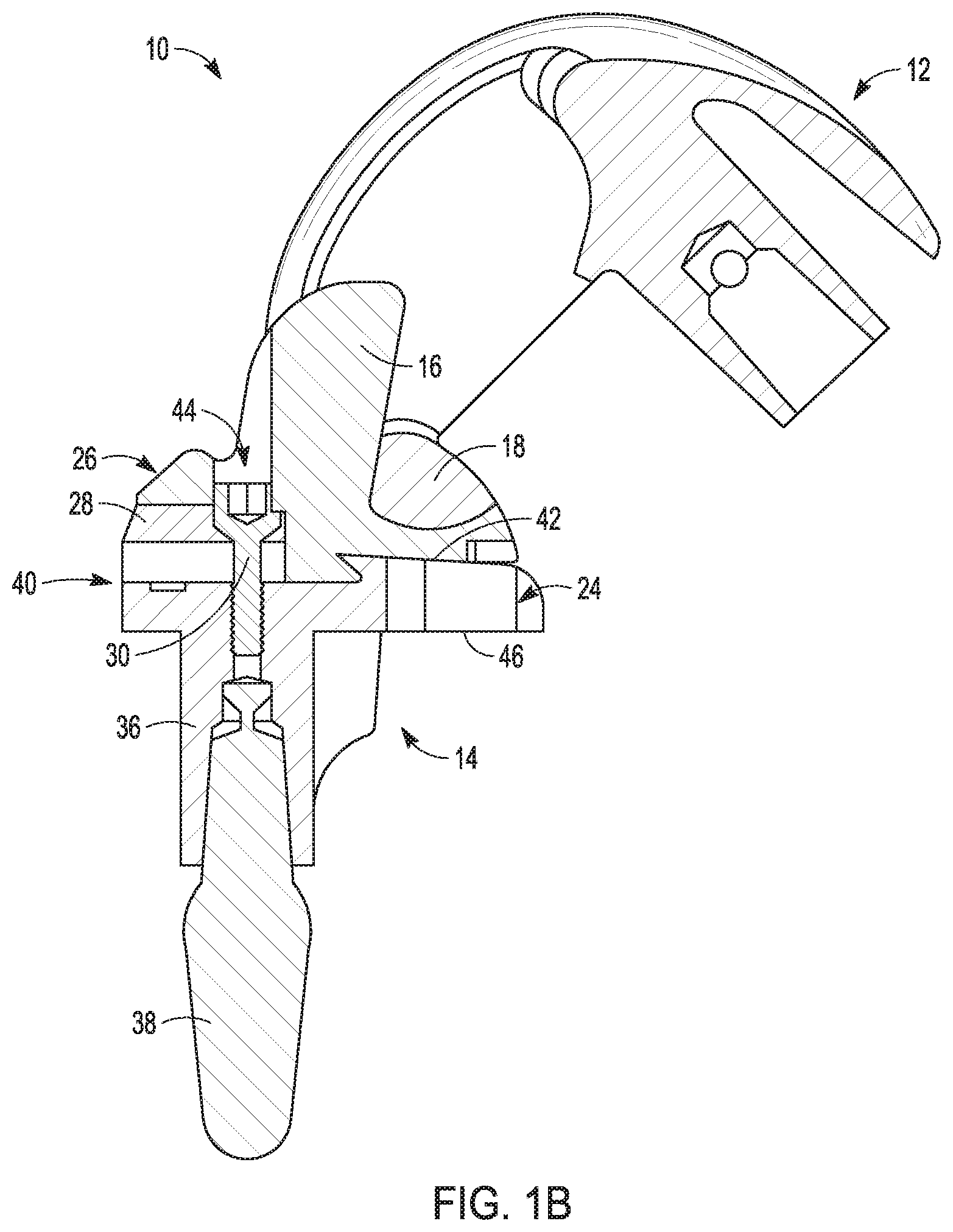
[0045] FIGS. 1A and 1B illustrate a prosthesis assembly 10 that can include a femoral prosthesis 12 and a tibial prosthesis 14. In the example of FIG. 1A, the prosthesis assembly 10 is shown in a perspective view with the femoral prosthesis 12 articulated relative to the tibial prosthesis 14 to 135.degree. of flexion. FIG. 1B shows the prosthesis assembly 10 in a cross-sectional view along a sagittal plane. The sagittal plane extends along the anterior-posterior direction and the proximal-distal direction of the prosthesis assembly 10.
[0046] According to the examples provided herein, the prosthesis assembly 10 can comprise a posterior stabilized (PS) prosthesis. Thus, the tibial prosthesis can include a spine 16 and the femoral prosthesis 12 can include a cam 18 (FIG. 1B). The spine 16 and the cam 18 can designed to cooperate with one another to stabilize femoral prosthesis 12 with respect to tibial prosthesis 14 in lieu of a posterior cruciate ligament (PCL). However, other prosthesis designs are contemplated including a mid-level constraint (MLC) design, a cruciate retaining (CR) design, and an ultra-congruent (UC) design, for example. The CR and UC designs omit the spine 16 and cam 18, such that femoral prosthesis 12 defines an intercondylar space between medial and lateral condyles 20 and 22 (only one shown in FIG. 1B) that is entirely open and uninterrupted by the cam 18. CR tibial prostheses are generally used in surgical procedures which retain the PCL.
[0047] Turning to the components illustrated in FIG. 1A and/or FIG. 1B, the tibial prosthesis 14 can include a tibial bearing component 26, a tibial baseplate 24, an insert 28, and a fastener 30 (FIG. 1B). The tibial bearing component 26 can include the spine 16, a proximal medial articular surface 32 and a proximal lateral articular surface 34. The tibial baseplate 24 can include a keel 36. Additional components such as a stem 38 can be used with the prosthesis assembly 10 in some examples.
[0048] As shown in FIGS. 1A and 1B, the femoral prosthesis 12 can be disposed atop and can articulate relative to the tibial prosthesis 14. Such articulation can be between the medial and lateral condyles 20 and 22 and the proximal medial articular surface 32 and the proximal lateral articular surface 34, respectively. The proximal medial articular surface 32 and the proximal lateral articular surface 34 can be shaped (e.g., curved) to facilitate such articulation during knee joint flexion. The spine 16 of the tibial bearing component 26 can be centrally located between the proximal medial articular surface 32 and the proximal lateral articular surface 34 as shown in FIG. 1A. The spine 16 can be configured to engage with the cam 18 during flexion as shown in FIG. 1B. Such engagement provides additional stability that would otherwise be offered by ligaments such as the PCL.
[0049] The tibial bearing component 26 can be secured to the tibial baseplate 24 as shown in FIGS. 1A and 1B. Such securement can be facilitated by the use of rails, notches, bosses and other features that will be described subsequently. Additionally, as shown in FIG. 1B, the insert 28 and the fastener 30 can be used to further secure the tibial beating component 26 to the tibial baseplate 24 as will be described subsequently.
[0050] As shown in FIG. 1B, the insert 28 can be disposed within a recess 40 of the tibial bearing component 26 atop a proximal surface 42 of the tibial baseplate 24 when assembled. The fastener 30 can extend at least partially through an aperture 44 into the recess 40 and can engage the insert 28 along a head portion thereof. The fastener 30 can additionally extend to fasten to the tibial baseplate 24 along a threaded portion as illustrated and described subsequently. As will be further discussed subsequently, features of the insert 28, fastener 30, tibial baseplate 24 and tibial bearing component 26 reduce micro-motion of the tibial bearing component 26 relative to the tibial baseplate 24.
[0051] In addition to the proximal surface 42, the tibial baseplate 24 has a distal surface 46 configured to interface with and abut a resected surface of the tibia (not shown). The keel 36 extends generally distal of the distal surface 46 according to the example of FIGS. 1A and 1B. The keel 36 can be configured to be received in a corresponding recess within the tibia to facilitate fixation of the tibial baseplate 24 to the tibia. However, according to other examples the tibial baseplate 24 can use additional or other features (i.e. features additional to or other than the keel 36) to facilitate fixation to the tibia including bone cement, spikes, augments and/or pegs. Thus, the keel 36 and stem 38 need not be utilized in all examples.
[0052] FIG. 2 shows a second example of a prosthesis assembly 110 of similar construction to the prosthesis assembly 10 of FIGS. 1A and 1B. However, in FIG. 2 the location of the aperture 144 has been altered relative to the aperture 44. The aperture 144 does not pass through the spine 116 in the embodiment of FIG. 2 but is disposed anterior thereof. In contrast, the aperture 44 passed through an anterior portion of the spine 16 as shown in FIGS. 1A and 1B. Thus, it is contemplated that the aperture 44, 144 can be disposed in a plurality of positions including passing through at least a portion of the spine, anterior of the spine or posterior of the spine.
[0053] FIG. 2 additionally shows the femoral prosthesis 12 articulated to an extension position relative to the tibial prosthesis 14. In such position, the cam 18 can be disposed out of contact with the spine 116.
[0054] Thus, as shown in one or more of FIGS. 1A, 1B and 2, the tibial bearing component 26 can have medial and lateral proximal articular surfaces 32, 34 (FIG. 1A) and an opposing distal surface 35 (FIG. 2). The tibial bearing component 26 can define at least one recess 40 therein with the recess 40 having an opening at a periphery of the tibial bearing component 26. The tibial baseplate 24 can be coupled to the tibial bearing component 26 on the proximal surface 42 thereof and having a distal surface 45 configured to be disposed on a resected proximal surface of a tibia. The insert 28 can be configured to be disposed within the recess 40 and can engage the tibial baseplate 24 and the tibial bearing component 26. The fastener 30 can be insertable into the tibial bearing component 26 and can be configured to retain the insert 28 to the tibial baseplate 24.
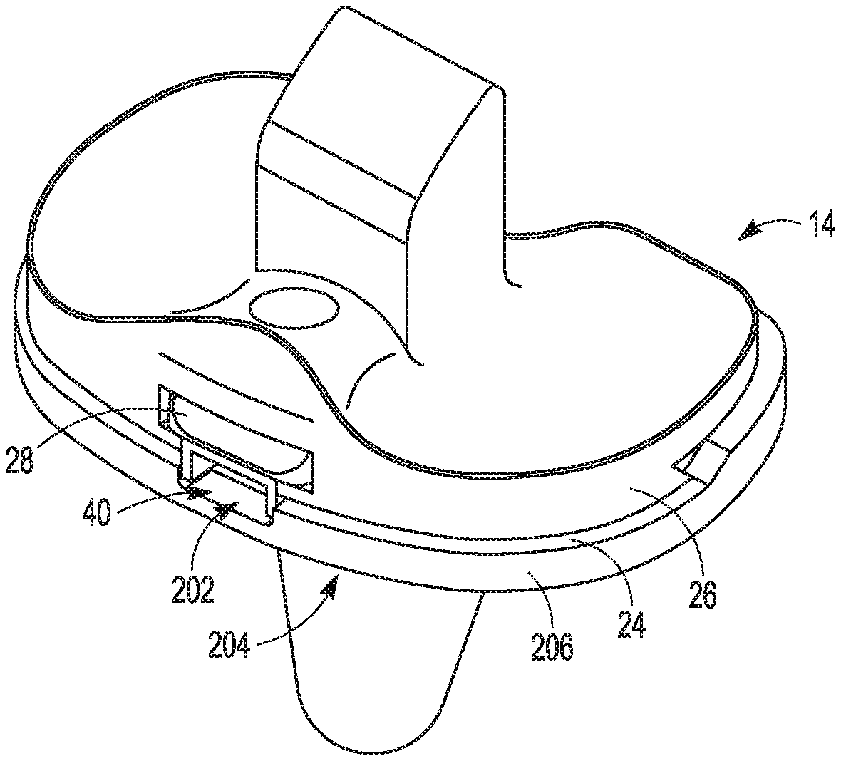
[0055] FIGS. 3A-3D illustrate a method 200 by which the tibial prosthesis 14 can be assembled. The method 200 includes passing the insert 28 through a peripheral opening 202 and into the recess 40 formed in the tibial bearing component 26 as shown in FIGS. 3A and 3B. The method engages a portion (e.g., tab 306 in FIG. 5) of the insert 28 with the tibial bearing component 26 while having first and second wings (described and number subsequently in reference to FIGS. 4A-5B) of the insert 28 received in corresponding grooves (described and number subsequently in reference to FIG. 4A) that are part of the recess 40. A tool can be used in some instances to facilitate passing the insert 28 and engagement as described above. The tool can also facilitate removal of the insert 28 from the recess 40 in some examples.
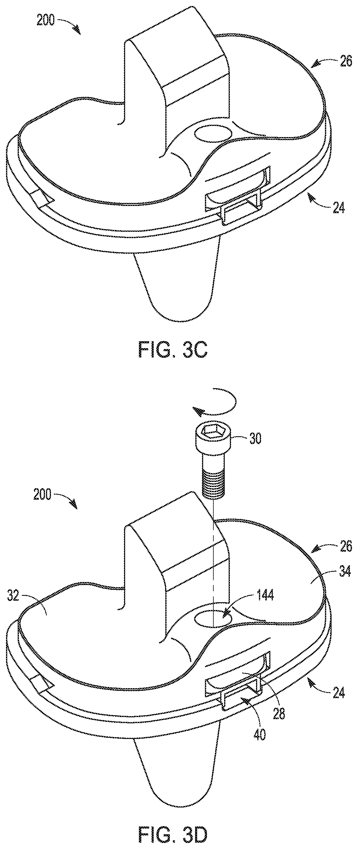
[0056] The method 200 can engage the tibial bearing component 26 with the tibial baseplate 24 as shown in FIG. 3C. This can initially be accomplished with engagement features such as dovetail boss, rails, notches or the like as will be illustrated and described subsequently. The insert 28 can be fastened to the tibial baseplate 24 as is initially demonstrated in FIG. 3D by passing the fastener 30 through the aperture 144 and into the recess 40 to engage the insert 28. The fastener 30 can then be rotated to thread with the tibial baseplate 24 to secure the insert 28 to the tibial baseplate 24 and thereby secure the tibial bearing component 26 to the tibial baseplate 24.
[0057] As will be discussed and illustrated in reference to further FIGURES subsequently, fastening the insert 28 to the tibial baseplate 24 can include passing the fastener 40 through a region located between medial and lateral proximal articular surfaces 32, 34 of the tibial bearing component 26 (the location of the aperture 144) as shown in FIG. 3D. The method 200 can also engage a first foot of the insert with a first portion of a rail of the tibial baseplate and can engage a second foot of the insert with a second portion of the rail of the tibial baseplate as will be discussed subsequently in reference to FIGS. 4 and 4A.
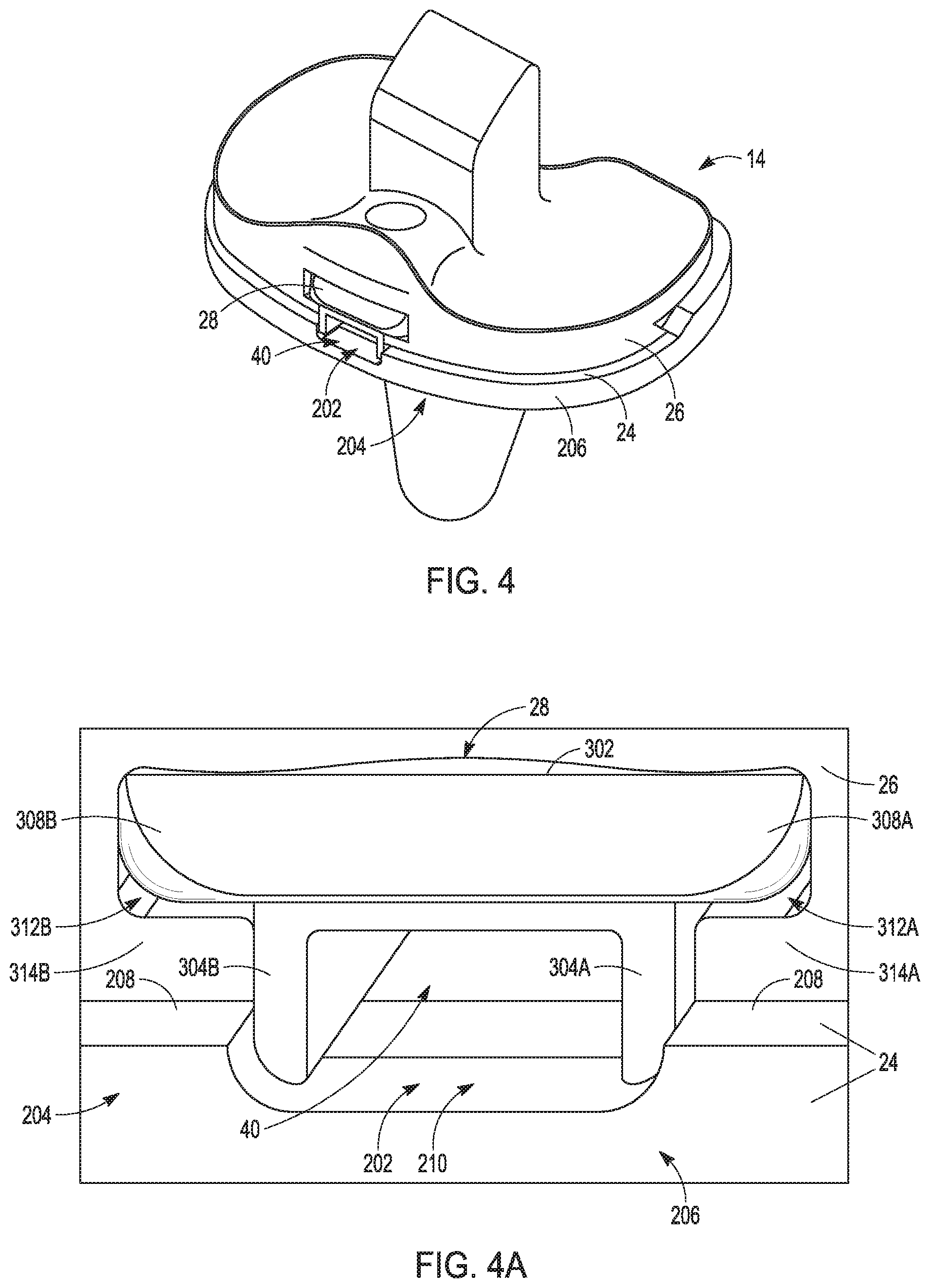
[0058] FIG. 4 shows the assembled tibial prosthesis 14. FIG. 4A is an enlarged view of an anterior portion of the tibial baseplate 24, the tibial bearing component 26 and the insert 28.
[0059] As is best shown in FIG. 4A, the insert 28 can be positioned in the recess 40 and can be configured to engage portions of the tibial baseplate 24. More particularly, the insert 28 can include a body 302, a first foot 304A and a second foot 304B as shown in FIGS. 4A, 5 and 5A. A tab 306 can project proximal of the body 302 as shown in FIGS. 5 and 5B. The body 302 can include first and second wings 308A and 308B that extend outward of the first foot 304A and second foot 304B, respectively. According to one example, the first wing 308A extends lateral of the first foot 304A and the second wing 308B extends medial of the second foot 304B.
[0060] As shown in FIGS. 4 and 4A, the opening 202 can be located at an anterior portion 204 of a periphery 206 of the tibial bearing component 26. The insert 28 can be disposed in the recess 40 such that substantially an entirety or all of the insert 28 is disposed therein. Additionally, when disposed in the recess 40, substantially an entirety of the insert 28 can be disposed anterior of the fastener 30 (FIGS. 1B and 2).
[0061] As shown in FIG. 4A, the tibial baseplate 24 can include a rail 208 extending from the proximal surface 42 along the periphery 206. The rail 208 has a gap 210. The gap 210 can be part of the opening 202, and therefore, can comprise part of the recess 40. In some examples, part of the rail 208 and gap 210 can be disposed anterior of the recess 40 and opening 202. The example of FIG. 4A illustrates that with the insert 28 disposed in the recess 40, at least a portion of the insert 28 extends into the gap 210 and engages the rail 208 (e.g. along the medial and lateral side surfaces of the first foot 304A and second foot 304B as shown subsequently in FIGS. 5 and 5A). Such engagement, along with engagement of the insert 28 against the proximal surface 42, can limit micro-motion of the tibial bearing component 26 relative to the tibial baseplate 24 with securement of the fastener 30.
[0062] As shown in FIG. 4A, the first and second wings 308A and 308B are configured to be received in corresponding grooves 312A and 312B that are part of the recess 40. The grooves 312A and 212B are shaped similar to the wings 308A and 308B. The wings 308A and 308B can be disposed on and engage projections 314A, 314B that form a distal portion of the grooves 312A and 312B.
[0063] Turning to FIGS. 5-5B, the body 302 can have an aperture 320 defined thereby. The aperture 320 can be configured to receive a head of the fastener 30 as was previously illustrated in FIGS. 1B and 2. More particularly, according to some examples the aperture 320 can be hemispherical in shape along a portion thereof so as to facilitate centering of the fastener 30 during insertion. The hemispherical shape can also minimize stretch loss of the fastener 30 due to settling of the fastener 30 during use. In some examples, such as that of FIG. 5B, an axis A of the aperture 320 can be angled relative to a proximal-distal axis PDA of the insert 28. This causes the fastener 30 to be angled in a direction in addition to the proximal-distal direction such as the anterior-posterior direction.
[0064] The first foot 304A can be connected to the body 302 and can extend distal therefrom in a direction generally perpendicular to that of wing 308A. As shown in FIG. 5A, in addition to a distal surface 322A, the first foot 304A can have a lateral side surface 324A engaging the tibial baseplate 24 when assembled as illustrated and described above in reference to FIG. 4A. Similarly, the second foot 304B can be connected to the body 302 and can extend distal therefrom. The second foot 304B can be spaced from the first foot 304A. The second foot 304B can have a distal surface 322B and can have a medial side surface 324B engaging the tibial baseplate 24 when assembled as illustrated and described above in reference to FIG. 4A.
[0065] The tab 306 can extend proximally from the body 304 and can engage the tibial bearing component 26 to temporarily retain the insert 28 within the tibial bearing component 26 such as illustrated in FIG. 3B of the method 200. More particularly, the tab 306 has an anterior face 307 (FIG. 5B) that engages a corresponding surface of the tibial bearing component 26 so as not to allow the insert 28 to be withdrawn from the recess 40 such as in the posterior-to-anterior direction (an opposing direction to the direction of insertion of the insert 28 into the recess 40 as shown in FIG. 3A).
[0066] FIG. 6 shows an example of the fastener 30 in greater detail. The fastener 30 can have a head portion 402 and a threaded portion 404. FIG. 6 provides an enlargement of the threaded portion 404. As discussed with regard to the insert 28 of FIGS. 5-5B, the head portion 402 can share as a similar curvature as the aperture 320. For example, the head portion 402 can be provided with a hemispherical configuration similar to that of the aperture 320 so as to facilitate centering of the screw during insertion (e.g. the conformity of the hemispherical head and the insert can be anywhere between a 1:1 and a 1:1.2 ratio, inclusive). Such configuration can also minimize stretch loss due to the fastener settling. A neck region 406 between the head portion 402 and the thread portion can have a necked down area with a diameter smaller than a minor diameter of the threaded portion 404. This can prevent notching of the neck region 406 during fabrication.
[0067] As shown in FIG. 6, the threaded portion 404 can include rounded root radii and the minor diameter can be relative to a major diameter to improve the strength of the fastener relative to that of a standard thread.
[0068] FIGS. 7-7C show a tibial bearing component 526 similar in construction to that of tibial bearing component 26 save that the disposition of an aperture 544 such so as to extend through at least an anterior portion of the spine 16. Thus, an anterior portion 502 of the spine 16 has a cut-out 504 as shown in FIG. 7. All other features of the tibial bearing component 526 are similar to or identical to those of the tibial bearing component 26 as previously described.
[0069] As shown in FIG. 7A, the spine 16 can be centrally located between the medial articular surface 32 and the lateral articular surface 34. A posterior region 506 of the spine 16 can have a radius such that the posterior region 506 is convexly shaped in a medial-lateral direction when viewed in a transverse plane. In contrast, the anterior portion 502 can be substantially flat when viewed in the transverse plane.
[0070] FIG. 7B shows a plan view of the distal surface 35 of the tibial bearing component 526. FIG. 7B additionally shows the recess 40. It should be noted that although the recess 40 and corresponding insert 28 are shown positioned at the anterior region and extending to an anterior periphery of the tibial bearing component 26 and the tibial baseplate 24 in the examples provided, in other embodiments the recess 40 and insert 28 can be disposed in other locations of the tibial bearing component 26 and the tibial baseplate 24. Additionally, although a substantially anterior-posterior insertion direction for the insert 28 into the recess 40 was illustrated and described, in other examples the insertion direction can be in another direction (e.g., medial-lateral, proximal-distal) or combinations of directions (e.g., medial-lateral and anterior-posterior).
[0071] FIG. 7B also illustrates additional connection mechanisms such as a double dovetail notch 508 and peripheral notches 510A and 510B these features are configured to attach to a double dovetail boss 512 and undercut rails 514A, 514B, respectively of the tibial baseplate 24 as shown in FIG. 8A. Upon assembly, the tibial bearing component 26, 126, 526 can be advanced along a path, such that tibial bearing component 26, 126, 526 moves along a generally anterior-to-posterior path as the double dovetail notch 508 begins to engage with the double dovetail boss 512 and the peripheral notches 510A and 510B begin to engage with the undercut rails 514A, 514B. Further posterior movement of the tibial bearing component 212 causes a tight interfitting engagement between these features. As is discussed and illustrated further in reference to FIG. 3, further engagement and securement of the tibial bearing component 26, 126 526 to the tibial baseplate 24 is facilitated by the insert 28 and the fastener 30.
[0072] As was previously shown in reference to FIGS. 1B and 2, the aperture 44, 144, 544 can be configured to receive at least a portion of the fastener 30 (FIGS. 1B and 2) therein. Indeed, upon assembly a head portion of the fastener 30 may remain in the aperture 44, 144, 544. According to the example of FIG. 7C, the aperture 544 can be angled (along axis B) relative to a proximal-distal axis (not shown) of the tibial bearing component 526 such that the aperture 544 extends both proximal-distal and anterior-posterior. The angle can be in a manner similar or identical to that provided for the aperture 320 of the insert 28 as previously discussed. In other examples, the aperture and/or aperture of the insert 28 can be angled in any manner desired not just in the proximal-distal and anterior-posterior manner illustrated.
[0073] FIGS. 7B and 7C illustrate the recess 40 in further detail including the grooves 312A and 312B (FIG. 7B). FIGS. 7B and 7C also show a notch 516 that can form a part of the recess 40. The notch 516 can be positioned anterior of the aperture 544 along a proximal portion of the recess 40. The notch 516 is configured to receive the tab 306 (FIGS. 5 and 5B) when the insert 28 is received in the recess 40. An anterior surface 518 that forms a part of the notch 516 is configured to engage the anterior face 307 (FIG. 5B) of the insert 28. This engagement can temporarily restrict movement of the insert 28 such that the insert cannot easily be withdrawn from the recess 40 such as in the posterior-to-anterior direction (an opposing direction to the direction of insertion of the insert 28 into the recess 40 as shown in FIG. 3A).
[0074] FIGS. 8A and 8B show the tibial baseplate 24. In particular, FIG. 8A shows the proximal surface 42 of the tibial baseplate 24. FIG. 8B shows a plan view of a proximal portion of the tibial baseplate 24. Additional features shown include the rail 208 extending from the proximal surface 42 along the periphery 206. The rail 208 has the gap 210 as previously discussed in reference to FIG. 4A. The gap 210 can be part of the opening 202, and therefore, can comprise part of the recess 40. As shown in FIG. 8A, the tibial baseplate 24 can also include the double dovetail boss 512 and the undercut rails 514A, 514B as previously discussed.
Additional Notes
[0075] The above detailed description includes references to the accompanying drawings, which form a part of the detailed description. The drawings show, by way of illustration, specific embodiments in which the invention can be practiced. These embodiments are also referred to herein as "examples." Such examples can include elements in addition to those shown or described. However, the present inventors also contemplate examples in which only those elements shown or described are provided. Moreover, the present inventors also contemplate examples using any combination or permutation of those elements shown or described (or one or more aspects thereof), either with respect to a particular example (or one or more aspects thereof), or with respect to other examples (or one or more aspects thereof) shown or described herein.
[0076] In this document, the terms "a" or "an" are used, as is common in patent documents, to include one or more than one, independent of any other instances or usages of "at least one" or "one or more." In this document, the term "or" is used to refer to a nonexclusive or, such that "A or B" includes "A but not B," "B but not A," and "A and B," unless otherwise indicated. In this document, the terms "including" and "in which" are used as the plain-English equivalents of the respective terms "comprising" and "wherein." Also, in the following claims, the terms "including" and "comprising" are open-ended, that is, a system, device, article, composition, formulation, or process that includes elements in addition to those listed after such a term in a claim are still deemed to fall within the scope of that claim. Moreover, in the following claims, the terms "first," "second," and "third," etc. are used merely as labels, and are not intended to impose numerical requirements on their objects.
[0077] The above description is intended to be illustrative, and not restrictive. For example, the above-described examples (or one or more aspects thereof) can be used in combination with each other. Other examples can be used, such as by one of ordinary skill in the art upon reviewing the above description. The Abstract is provided to comply with 37 CFR. .sctn. 1.72(b), to allow the reader to quickly ascertain the nature of the technical disclosure. It is submitted with the understanding that it will not be used to interpret or limit the scope or meaning of the claims. Also, in the above detailed description, various features can be grouped together to streamline the disclosure. This should not be interpreted as intending that an unclaimed disclosed feature is essential to any claim. Rather, inventive subject matter can lie in less than all features of a particular disclosed example. Thus, the following claims are hereby incorporated into the detailed description as examples or embodiments, with each claim standing on its own as a separate example, and it is contemplated that such examples can be combined with each other in various combinations or permutations. The scope of the invention should be determined with reference to the appended claims, along with the full scope of equivalents to which such claims are entitled.
* * * * *
D00000
D00001
D00002
D00003
D00004
D00005
D00006
D00007
D00008
D00009
D00010
D00011
XML
uspto.report is an independent third-party trademark research tool that is not affiliated, endorsed, or sponsored by the United States Patent and Trademark Office (USPTO) or any other governmental organization. The information provided by uspto.report is based on publicly available data at the time of writing and is intended for informational purposes only.
While we strive to provide accurate and up-to-date information, we do not guarantee the accuracy, completeness, reliability, or suitability of the information displayed on this site. The use of this site is at your own risk. Any reliance you place on such information is therefore strictly at your own risk.
All official trademark data, including owner information, should be verified by visiting the official USPTO website at www.uspto.gov. This site is not intended to replace professional legal advice and should not be used as a substitute for consulting with a legal professional who is knowledgeable about trademark law.