Retrieval Device
Ranallo; Cynthia Ann ; et al.
U.S. patent application number 16/846581 was filed with the patent office on 2020-07-30 for retrieval device. This patent application is currently assigned to UNITED STATES ENDOSCOPY GROUP, INC.. The applicant listed for this patent is UNITED STATES ENDOSCOPY GROUP, INC.. Invention is credited to Scott Haack, Christopher Kaye, Joseph Michelini, Cynthia Ann Ranallo, Alex Uspenski.
| Application Number | 20200237395 16/846581 |
| Document ID | 20200237395 / US20200237395 |
| Family ID | 1000004752470 |
| Filed Date | 2020-07-30 |
| Patent Application | download [pdf] |


View All Diagrams
| United States Patent Application | 20200237395 |
| Kind Code | A1 |
| Ranallo; Cynthia Ann ; et al. | July 30, 2020 |
RETRIEVAL DEVICE
Abstract
The present subject matter provides improvements of endoscopic retrieving devices. In specific, the present subject matter provides a net element with an extra wide tail section. The present subject matter provides a new weaving pattern. The present subject matter provides a new shape of the loop. The present subject matter provides a net with a combination of net elements, such as combinations of different net geometries and/or different net materials. The present subject matter provides a new and inventive loop. The present subject matter provides an improved second end of the tubular member. The present subject matter provides a new and inventive arm.
| Inventors: | Ranallo; Cynthia Ann; (Eastlake, OH) ; Uspenski; Alex; (Chardon, OH) ; Michelini; Joseph; (Painesville, OH) ; Kaye; Christopher; (Eastlake, OH) ; Haack; Scott; (Moreland Hills, OH) | ||||||||||
| Applicant: |
|
||||||||||
|---|---|---|---|---|---|---|---|---|---|---|---|
| Assignee: | UNITED STATES ENDOSCOPY GROUP,
INC. Mentor OH |
||||||||||
| Family ID: | 1000004752470 | ||||||||||
| Appl. No.: | 16/846581 | ||||||||||
| Filed: | April 13, 2020 |
Related U.S. Patent Documents
| Application Number | Filing Date | Patent Number | ||
|---|---|---|---|---|
| 15866273 | Jan 9, 2018 | |||
| 16846581 | ||||
| 62444144 | Jan 9, 2017 | |||
| Current U.S. Class: | 1/1 |
| Current CPC Class: | A61B 17/320016 20130101; A61B 90/92 20160201; A61B 17/32056 20130101; A61B 2017/00367 20130101; A61B 17/00234 20130101; A61B 17/221 20130101; A61B 2017/2217 20130101; A61B 2017/00358 20130101; A61B 2017/00438 20130101; A61B 2017/2212 20130101 |
| International Class: | A61B 17/3205 20060101 A61B017/3205; A61B 17/32 20060101 A61B017/32; A61B 17/221 20060101 A61B017/221; A61B 90/92 20060101 A61B090/92; A61B 17/00 20060101 A61B017/00 |
Claims
1. An endoscopic device for retrieving an object from within a human body, the device comprising: a transmitting assembly comprising: a handle; and a link having a first end attached to the handle and a second end; a wire defining a loop portion and a leg portion, wherein the leg portion is disposed proximal from the loop portion and a proximal end of the leg portion is secured to the second end of the link; a net element having a loop section secured to the loop portion, wherein the loop portion is movable between an expanded position and a collapsed position by action of the handle relative to the base, and wherein a widest portion of the loop portion is more proximal to a proximal end of the loop portion than a mid-point of the length of the loop portion.
2. The endoscopic device of claim 1, wherein a distance from the mid-point of the length of the loop to the widest portion of the loop is about 3%-45% of the length.
3. The endoscopic device of claim 2, wherein the distance from the mid-point of the length of the loop to the widest portion of the loop is about 10%-35% of the length.
4. The endoscopic device of claim 3, wherein the distance from the mid-point of the length of the loop to the widest portion of the loop is about 12%-25% of the length.
5. The endoscopic device of claim 1, wherein the net element further comprises a tail section secured to the link.
6. The endoscopic device of claim 5, wherein the tail section is secured to the link by a tether.
7. The endoscopic device of claim 5, wherein the tail section has a width of 10-25 mm.
8. The endoscopic device of claim 5, wherein the loop portion passes through the net element, loops over the edges of the net element, and passes through the net element again from the same face.
9. The endoscopic device of claim 5 further comprising a plurality of the following patterns: the loop portion passing through the net element, looping over the edges of the net element, and passing through the net element again from the same face.
10. The endoscopic device of claim 5, wherein the leg portion passes through the tail section at a position between about 1 mm to 6 mm from a corner defined between the tail section and the loop section of the net element.
11. The endoscopic device of claim 10 further comprising: a second leg portion, and wherein both leg portions pass through the tail section at a position between about 1 mm to 6 mm from the corner.
12. The endoscopic device of claim 10, wherein the leg portion passes through the tail section at a position between about 2 mm to 5 mm from the corner.
13. The endoscopic device of claim 12 further comprising: a second leg portion, and wherein both leg portions pass through the tail section at a position between about 2 mm to 5 mm from the corner.
14. The endoscopic device of claim 5, wherein the leg portion passes through the tail section at a position at least about 4 mm from a corner defined between the tail section and the loop section.
15. The endoscopic device of claim 14 further comprising: a second leg portion, and wherein both leg portions pass through the tail section at a position at least 2 mm from the corner.
16. The endoscopic device of claim 1, wherein the net element comprises combinations of different net geometries and/or different net materials.
17. The endoscopic device of claim 1, wherein the loop portion is configured to flex towards only one side.
18. The endoscopic device of claim 1 further comprising: a support assembly including a base and an elongated tubular member, wherein the handle is movable relative to the base, and the link extends through at least a portion of the tubular member.
19. The endoscopic device of claim 18, wherein a distal opening of the tubular member is enlarged or flared.
20. The endoscopic device of claim 18, wherein an inside surface or an outside surface of the distal portion of the tubular member is smooth and atraumatic.
Description
CROSS-REFERENCES
[0001] This application is a continuation of U.S. patent application Ser. No. 15/866,273, filed Jan. 9, 2018, which claims the benefit of U.S. Provisional Patent Application No. 62/444,144, filed Jan. 9, 2017, both disclosures of which are hereby incorporated herein by reference in their entirety.
TECHNICAL FIELD
[0002] The present subject matter is related to an endoscopic retrieval device.
BACKGROUND OF THE INVENTION
[0003] Endoscopic retrieval or removal devices are used to recover objects from inside a human subject. Such objects may include excised human tissue, including polyps, foreign objects, or food bolus. Some typical devices include forceps or clasps to grab objects. Certain devices of this type are not well-suited for retrieving heavy, rounded or blunt objects such as large tissue masses, a food bolus, coins, marbles and batteries because the objects are difficult to hold securely. Further, if an object is dropped near the trachea during the removal process, the results can be catastrophic for the patient. Other devices include a variety of net support and net operating structures.
[0004] Many retrieval devices are used within an instrument channel of an endoscope during endoscopic medical procedures. These devices are generally expandable and collapsible relative to a tube inserted into the instrument channel. For example, a wire loop at the distal end of the device may expand and collapse relative to the tube by action of a handle at the proximal end of the device. Further, a net may be secured to the expandable and collapsible wire loop.
SUMMARY
[0005] One aspect of the present subject matter is to provide a net element with an extra wide tail section. The tail section wraps around the link, the leg portion, or the connection.
[0006] Another aspect of the present subject matter is to provide a new weaving pattern. The loop passes through the net element, loops over the edges of the net element, and passes through the net element again from the same face. At least one leg of the loop passes through the tail section at a position at least about 4 mm from a corner defined between the tail section and the loop section of the net element.
[0007] Another aspect of the present subject matter is to provide a new shape of the loop. The widest portion of the loop is more proximal to the tubular member than the mid-point of the length of the loop is.
[0008] Another aspect of the present subject matter is to provide a net with a combination of net elements, such as combinations of different net geometries and/or different net materials.
[0009] Another aspect of the present subject matter is to provide a new and inventive loop. The loop is configured to flex towards only one side. The loop or the net is colored or coded to indicate which side is flexed.
[0010] Another aspect of the present subject matter is to provide an improved second end of the tubular member. The second opening of the tubular member is enlarged or flared. Also, the inside surface of the distal portion of the tubular member is smooth and atraumatic to the net.
[0011] Another aspect of the present subject matter is to provide a new and inventive arm. The distal ends of two arms are respectively attached to each side of the proximal portion of the loop. The proximal ends of the two arms are attached to the handle. The arms are configured to be pushed towards the distal direction to widen the loop.
BRIEF DESCRIPTION OF THE DRAWINGS
[0012] FIG. 1 is a perspective view of a retrieval device constructed in accordance with an embodiment of the present invention;
[0013] FIG. 2 is a view of a portion of the device of FIG. 1, showing the loop;
[0014] FIGS. 3a-3d are views of a portion of the device of FIG. 1, showing the loop and the net elements;
[0015] FIGS. 4a-4c are views of a portion of the device of FIG. 1, showing the loop, the net elements, and the tubular member;
[0016] FIG. 5 is a view of an embodiment of the net element;
[0017] FIG. 6 is a view of an embodiment of the net;
[0018] FIGS. 7a and 7b is views of an embodiment of the net weaving pattern;
[0019] FIG. 8 is a view of an embodiment of the loop;
[0020] FIGS. 9a-9c are side views of unassembled loops and net elements;
[0021] FIGS. 10a-10f are views of embodiments of the net;
[0022] FIGS. 11a and 11b are views of another embodiment of the net;
[0023] FIG. 12 is a view of another embodiment of the net;
[0024] FIG. 13 is a view of another embodiment of the net;
[0025] FIGS. 14a and 14b are views of another embodiment of the loop;
[0026] FIGS. 15a and 15b are views of another embodiment of the loop;
[0027] FIGS. 16a and 16b are views of embodiments of the tubular member; and
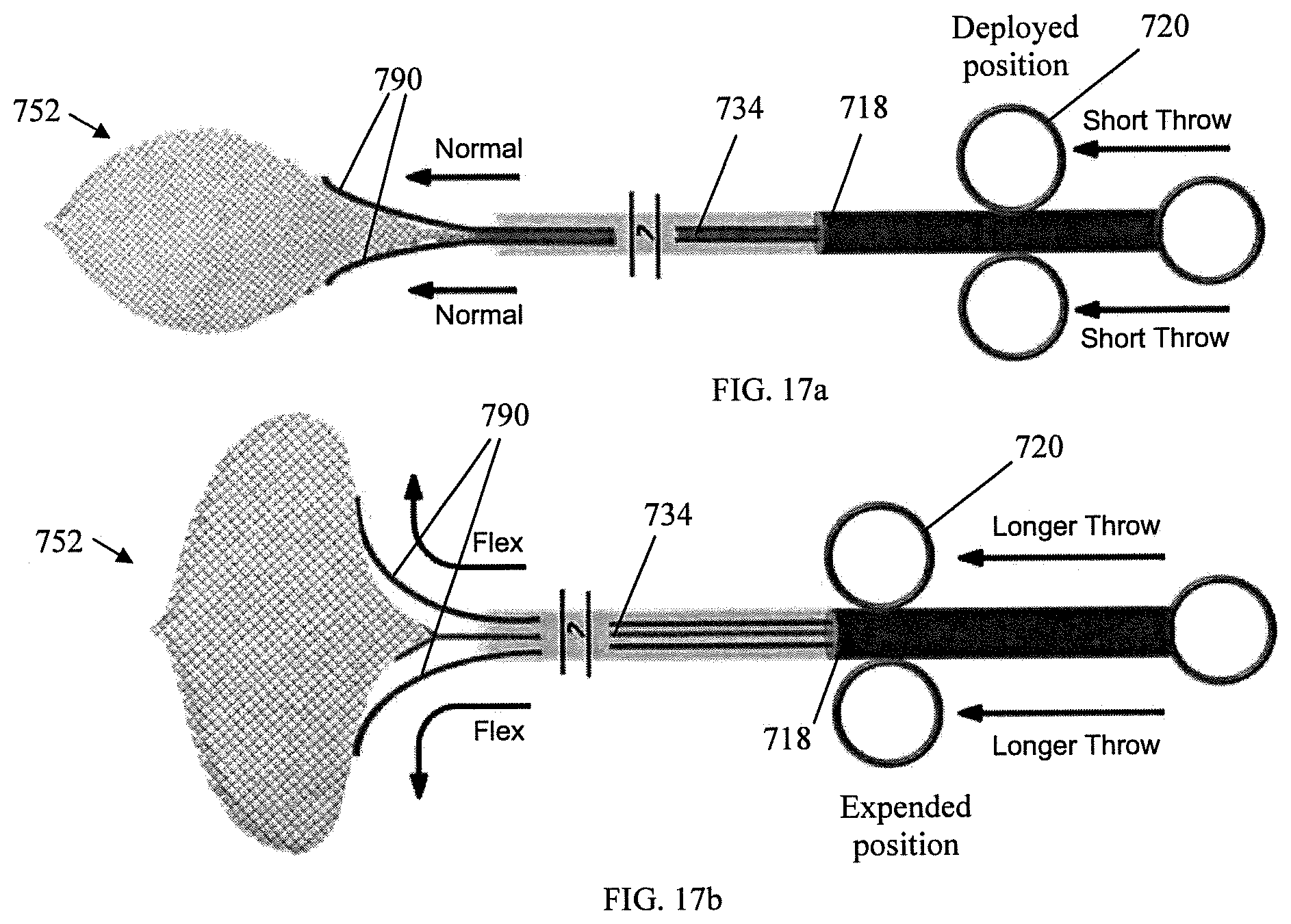
[0028] FIGS. 17a and 17b are views of an embodiment of an arm.
DETAILED DESCRIPTION
[0029] The Detailed Description merely describes preferred embodiments of the invention and is not intended to limit the scope of the invention or claims in any way. Indeed, the invention as described by the claims is broader than and unlimited by the preferred embodiments, and the terms used have their full ordinary meaning.
[0030] A device for retrieving an object from within a human subject is disclosed. In discussing the device, the terms distal and proximal are used with respect to the operator's hand. In other words, when the device is used within the instrument channel of an endoscope or similar device, the proximal and distal orientation are relative to the position of the surgeon or operator of the device.
[0031] It should also be noted that for the purposes of this application, the terms attach (attached), connect (connected), and link (linked) are not limited to direct attachment, connection, or linking but also include indirect attachment, connection, or linking with intermediate parts, components, or assemblies being located between the two parts being attached, connected, or linked to one another. In addition, the terms attach (attached), connect (connected), and link (linked) may include two parts integrally formed or unitarily constructed.
[0032] For exemplary purposes only, the invention will be discussed in regard to a device designed for use within an endoscope for retrieving objects within relatively tight passages, such as for example, impacted food bolus from the esophagus or polyps located within the gastrointestinal tract. It should be apparent to others with ordinary skill in the art that the discussion and Figures included in this application are by way of example only, and that the invention can be utilized with endoscopic retrieval devices having a wide variety of structures, shapes, strengths, or purposes. One of many other exemplary uses for the invention is to remove polyps from the colon.
[0033] Several exemplary devices for endoscopic retrieval of an object from within a subject are disclosed in U.S. Pat. No. 5,906,621 to Secrest et al.; U.S. Pat. No. 6,814,739 to Secrest et al.; U.S. Pat. No. 8,016,838 to Secrest et al.; U.S. Pat. No. 8,057,484 to Secrest et al.; U.S. Pat. No. 8,591,521 to Cherry et al.; U.S. Pat. No. 9,204,888 to Cherry et al.; U.S. Pat. No. 9,486,188 to Secrest et al.; U.S. Pat. No. 9,730,716 to Secrest et al.; U.S. Pat. No. 9,826,997 to Cherry et al.; U.S. application Ser. No. 15/676,725 to Secrest et al.; U.S. application Ser. No. 15/875,028 to Cherry et al., each of which incorporated herein by reference in its entirety, to the extent that any do not conflict with the present application.
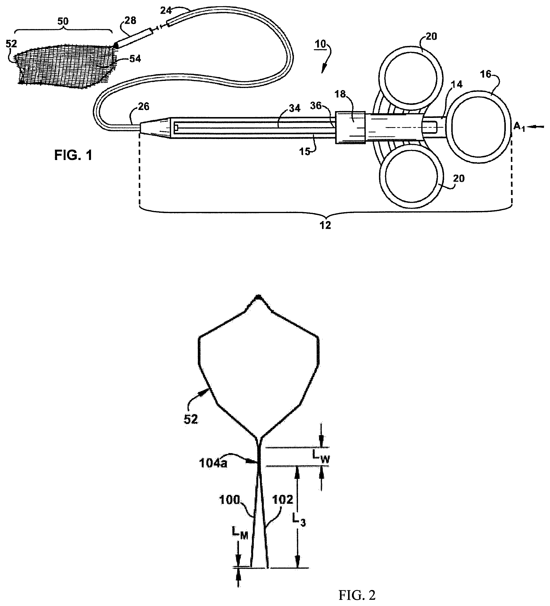
[0034] An endoscopic surgical device 10 for retrieving excised tissue and or foreign bodies from within a subject is illustrated in FIG. 1. The device 10 is so constructed and arranged that it may be inserted into a subject through an orifice or small incision and operated to retrieve a tissue sample previously detached from the subject by a conventional method, e.g., a snare/cautery system. Often, the endoscopic surgical device 10 is delivered via a channel located in and through an endoscope.
[0035] The device 10 can be used with any suitable or conventional endoscopic or laparascopic surgical equipment. For purposes of this disclosure the device 10 is described in the context of use with an endoscope/colonoscope/sigmoidoscope type apparatus (not illustrated), of conventional or suitable construction. The scope is provided with an elongated body having a controllably flexible projecting end region. Surgical instruments, such as the device 10, may be introduced through an instrument channel, which extends through the scope body, for retrieving tissue targeted by the surgeon manipulating the scope.
[0036] FIG. 1 is a perspective view of a retrieval device 10 constructed in accordance with an embodiment of the present subject matter. The device 10 includes an actuating body 12 attached to a motion transmitting link 34 at a proximal end 36 of the motion transmitting link 34. By affecting the motion transmitting link 34, the actuating body 12 can transmit considerable deployment and retractive forces to a net 50 while enabling an endoscope body to be freely manipulated and flexed to position the net where desired. In other embodiments, the actuating body 12 can be any number of actuating devices or handles recognized by one of ordinary skill in the art.
[0037] In the particular embodiment shown in FIG. 1, the actuating body 12 includes a support base 14. The support base 14 includes a ring 16 at a proximal end. The actuating body 12 also includes a handle 18 having two rings 20. The handle 18 is mounted over an interior section 15 of the support base 14 and is movable relative to the support base in the direction A1 as illustrated, or in an opposing direction. For example, an operator may place a finger in each of the rings 20 and thumb of the same hand in the support base ring 16. By moving the two fingers in the direction A1, an operator can move the handle 18 relative to the support base 14. In contrast, the handle 18 can be slid in a direction opposite A1 by pulling one's fingers towards one's thumb.
[0038] The device 10 can also include an elongated introducer member or tubular member 24 having a first end 26 fixed to the support base 14 and a second end remote from the actuating body. The tubular member 24 and the support base 14 of the present embodiment are a fixed support assembly for the moving parts of the device 10. The tubular member 24 may be any suitable, small-diameter tube formed of a non-reactive low-friction flexible material, such as for example, polytetrafluorethylene. The tubular member 24 defines a lumen with an opening at the tubular member second end.
[0039] In the embodiment of FIG. 1, the motion transmitting link 34 is connected to the actuating body 12 via handle 18. The link can be a solid cable, a hollow tube, or any suitable elongated object or combination of objects for transferring axial motion and considerable deployment and retractive forces from the handle 18 to other parts of the device. The link 34 has first end 36 fixed to the handle 18 and a second end remote from the actuating body portion 12, connecting to retrieval net 50 via connection 28. The link extends substantially through the tubular member 24 lumen. The link may be constructed of any suitable rigid or semi-rigid material. The link may be one piece or formed from a series of pieces and connections, such as for example, hypodermic tubes, swage connections, and cables. In some embodiments, the link 34 is rotatable by the actuating body 18 having a rotation function. A rotatable link 34 is made of nitinol wire or other suitable wire. In some other embodiments, the rotatable link 34 has torque tube filar construction.
[0040] Still referring to FIG. 1, the device also includes a retrieval net 50. The retrieval net 50 is used by the operator to capture and retrieve objects from within a human subject. The retrieval net 50 includes a loop 52, or loop portion, and at least one net element 54 secured to the loop. The at least one net element 54 may be supported by the loop 52 by threading or weaving the loop through holes in the at least one net element. It may also be supported by sewing or otherwise attaching the net element to the loop through use of a thread or other sewed lines. However, the at least one net element 54 may be supported by the loop 52 by any suitable method known in the art, such as welding, melding, or gluing. Further, it should be apparent to others with ordinary skill in the art that a variety of net shapes and sizes can be utilized in the practice of this invention. Additional, inventive net and loop arrangements are described herein.
[0041] Referring now to FIG. 2, the loop 52 of the device of FIG. 1 is shown. The loop 52 is shown in FIG. 2 in a polygon form prior to assembly within the tubular member 24. The wire of the loop 52 extends back toward the proximal end of the device 10 and forms two adjacent, or leg, portions 100 and 102. The leg portions 100, 102 are secured to each other by a connection 104 a, such as for example, with a weld or by crimping or twisting the portions together, having an axial length Lw of sufficient size to secure the portions together. As shown, the leg portions 100, 102 are joined by a weld 104a. The leg portions 100, 102 extend beyond the weld 104a a length L3. The extension lengths of the two leg portions 100, 102 may be mismatched by a length Lm, but this mismatch is not required. The mismatch in extension lengths of the two leg portions 100, 102 allows space to connect the two leg portions to the link 34 through the connection 28 during manufacturing of the device.
[0042] Referring to FIG. 1., the connection 28 connects the second, distal end of the link 34 to retrieval net 50. The connection 28 may be a weld between the link 34 and the loop 52 or any means capable of attaching link 34 and the retrieval net 50 recognized by one of ordinary skill in the art, including adhesive or a threaded connection between the link 34 and the loop 52. The connection 28 may also be a junction between at least one net element 54 and link 34.
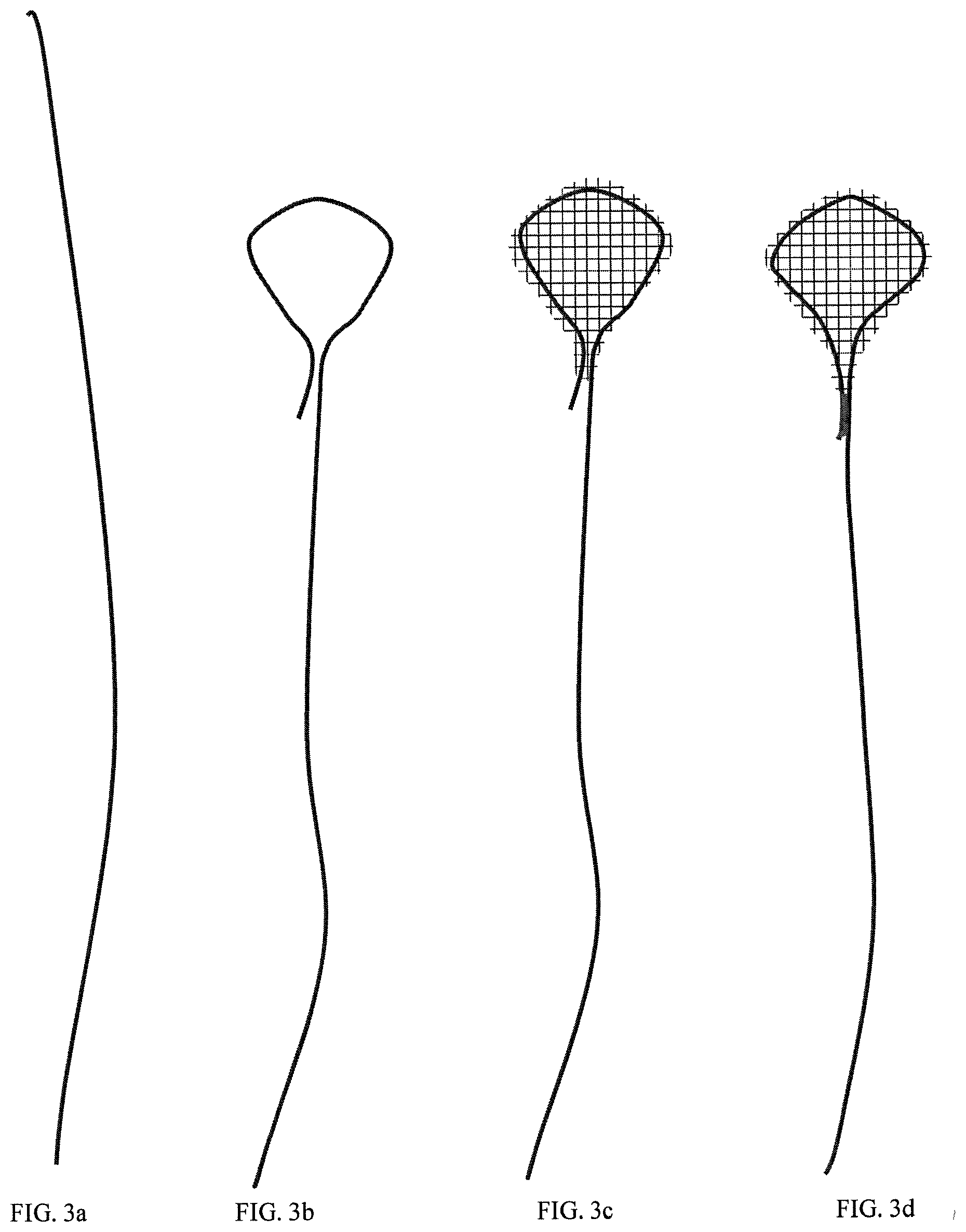
[0043] One of ordinary skill in the art should realize that the link 34, the connection 28, and the loop 52 could be formed by one wire. In the embodiments in FIG. 3a-3d, a single wire forms both the loop 52, the connection 28, and the link 34. The wire comprises a short leg and a long leg. The short leg welds, crimps, or otherwise bonds to the long leg and forms the loop. The wire may be made of nitinol or other suitable material. In the embodiments in FIG. 4a-4d, the single wire has two long legs. Both legs pass through the tubular member. One or more stops are configured to be tied, welded, crimped, or otherwise bonded to at least one leg. In such, the stops limit net migration. In some embodiments shown as FIG. 4b, one or more stops are added to the tubular member, and may be tied, welded or glued. The stops could be two "balls" or other features larger than net openings, or be a ball and socket that would help maintain the positional relationship of the wires as the net was retracted. Position could be a locking mechanism or merely passive positioning. FIG. 4c shows that the tubular member may comprise stops, such as a notch and an O-ring. One of ordinary skill in the art should understand that any modifications or structures on the tubular member, such as a crimp, glue or taper to decrease the inner diameter of the tubular member could be used to restrict the movement of net. In both instances, a tie or attachment may be needed. Such a tie or attachment is the most effective at the distal end. This would also help center the wires and net in the tubular member. In the embodiments of FIG. 4d, the two wire legs are welded, glued or crimped together, either a couple places or over the length, to give the legs rigidity.
[0044] As discussed, the retrieval net 50 is designed for resilient movement between two positions. FIG. 1 shows the retrieval net 50 in a deployed position. The retrieval net 50 can also be disposed within the tube 24 for deployment and retrieval through the tubular member lumen opening. By movement of the handle 18 relative to the body 14, the retrieval net 50 is movable between either the deployed or stored positions.
[0045] One aspect of the present subject matter is to provide a net element with an extra wide tail section. Referring to FIG. 5, the net element 154 comprises a loop section 180 and a tail section 190. The width W of the tail section 190 is about 10 mm-35 mm. In some embodiments, the width W of the tail section 190 is about 25 mm.
[0046] In some embodiments of FIG. 6, the tail section 190 was wrapped around the link 34 by tying a tether 195. In other embodiments, the tail section 190 wraps around at least one of the leg portions 100, 102. In other embodiments, the tail section 190 wraps around the connection 28. One of ordinary skill in the art should understand that the tail section is not necessarily tied by the tether 195, and could be welded or glued. The wider tail section 190 helps to prevent over stretching the proximal end of the net created by the net element when retrieving an object and thus reduces the chance of tearing the mesh. It also aides in packing the mesh into the tubular member 24.
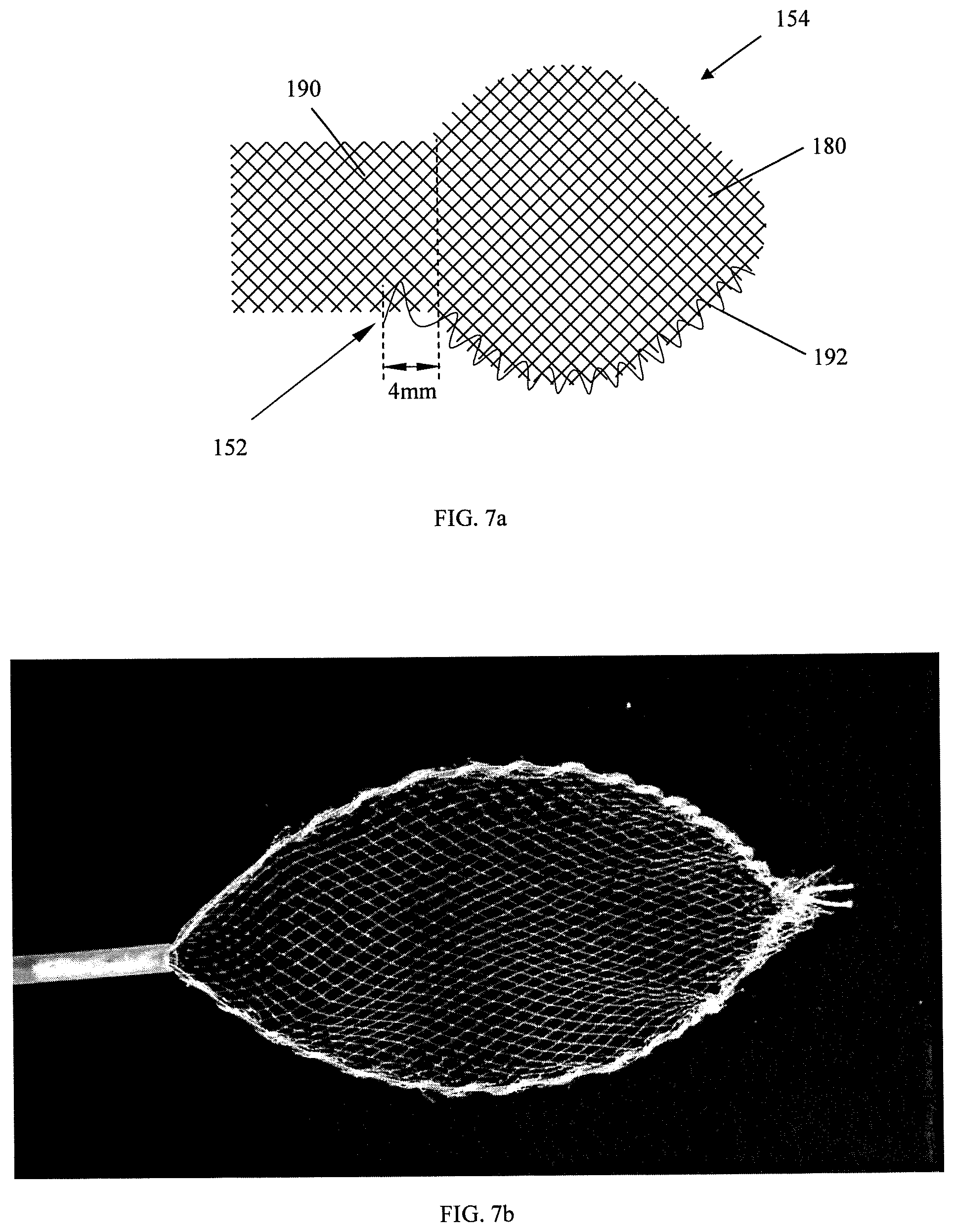
[0047] Another aspect of the present subject matter is to provide a new weaving pattern. Referring to FIG. 7a, in some embodiments, the loop 152 passes through the net element 154, loops over the edges of the net element 154, and passes through the net element 154 again from the same face. The loop 152 weaves following a direction 192. FIG. 7b shows a net having such a weaving pattern. Such weaving pattern helps with visualization while using the device.
[0048] In some embodiments, the loop 152 passes through the tail section 190. In some embodiments, one leg of the loop 152 passes through the tail section 190. In some other embodiments, both legs of the loop 152 pass through the tail section 190. In some other embodiments, at least one leg of the loop 152 passes through the tail section 190 at a position between about 1 mm to 6 mm from a corner defined between the tail section 190 and the loop section 180 of the net element 154. In some other embodiments, at least one leg of the loop 152 passes through the tail section 190 at a position between about 2 mm to 5 mm from a corner defined between the tail section 190 and the loop section 180 of the net element 154. In some embodiments, at least one leg of the loop 152 passes through the tail section 190 at a position at least about 4 mm from a corner defined between the tail section 190 and the loop section 180 of the net element 154. In some other embodiments, both legs of the loop 152 pass through the tail section 190 at a position between about 1 mm to 6 mm from a corner defined between the tail section 190 and the loop section 180 of the net element 154. In some other embodiments, both legs of the loop 152 pass through the tail section 190 at a position between about 2 mm to 5 mm from a corner defined between the tail section 190 and the loop section 180 of the net element 154. In some embodiments, both legs of the loop 152 pass through the tail section 190 at a position at least about 4 mm from a corner defined between the tail section 190 and the loop section 180 of the net element 154. In such, the weaving pattern helps to reduce wear of the net element when retracting the net into the tubular member.
[0049] Another aspect of the present subject matter is to provide a new shape of the loop. Referring to FIG. 8, in some embodiments, the loop 152 comprises a widest portion 166 and a length L measured between a proximal end and a distal end. The proximal end is defined where the loop begins to close during retraction into the tubular member, irrespective of where the loop connection physically may occur. The distal end is defined by the most distal end, or ends, of the loop 152. In any instance where there are proximal legs that are excessively long, and/or the distal tip is inverted or of any other unusual geometry, the midpoint shall be considered only with respect to the broad portions of the form, which is defined between the proximal end and the distal end(s). The widest portion 166 of the loop 152 is more proximal to the tubular member 24 than the mid-point of the length L of the loop 152 is. In other words, the widest portion 166 is closer to the tubular member 24 than the mid-point of the length L of the loop 152, such that the loop 152 is easier to be controlled during the procedures. In some embodiments, the distance D from the mid-point of the length L of the loop 152 to the widest portion 166 of the loop 152 is about 3%-45% of the length L. In some embodiments, the distance D from the mid-point of the length L of the loop 152 to the widest portion 166 of the loop 152 is about 10%-35% of the length L. In some embodiments, the distance D from the mid-point of the length L of the loop 152 to the widest portion 166 of the loop 152 is about 12%-25% of the length L.
[0050] Another aspect of the present subject matter is to provide a net with a combination of net elements, such as combinations of different net geometries and/or different net materials. Such a net provides better support and strength that otherwise could not be achieved by a single net geometry/material.
[0051] The net comprises at least a first net element and a second net element, respectively, having different geometry or material properties. The property differences may be caused by different alignments of multiple nets or multiple net pieces, weave densities, geometries, materials, or any combination of the above properties. For example, in some embodiments, the first and second net elements have different alignments or zones. In some embodiments, the first and second net elements have different weave densities. In some embodiments, the first and second net elements use different materials. In some embodiments, the first and second net elements have different geometries. As a result of an embodiment, the first net element is more elastic, while the second net element has more strength or resiliency.
[0052] Individual net element may, but not necessarily, fully cover the loop. In some embodiments, the first and second net elements respectively cover the whole loop. In some embodiments, one of the first and second net elements fully covers the loop; and another net element covers only a part of the loop. In some embodiments, none of the first and second net elements covers the whole loop. However, the first and second net elements connect each other to cover the whole loop.
[0053] Referring to FIGS. 9a-9c, in some embodiments shown in FIG. 9a, the first net element is attached to one side of the loop, while the second net is attached to another side of the loop. In some embodiments shown in FIG. 9b, the first and second nets are attached to the same side of the loop. In some embodiments shown in FIG. 9c, the first net element is attached to one side of the loop; and the second net element is attached the first net element, or vice versa. A person skilled may readily understand that the net element could be weld, glued, or otherwise attached by a known mechanism to the loop. Similarly, the second net element could be weld, glued, or otherwise attached by a known mechanism to the first net element.
[0054] A person skilled in the art should readily understand that the net elements discussed above could also include plastic film or plastic membrane, such as Tyvek, or a known material.
[0055] In the embodiments of FIGS. 10a-10f, the net 350 comprises the first and second net elements 3542, 3544. The first net element 3542 fully covers the loop 352. The second net element 3544 covers only a portion of the loop. The second net elements in FIGS. 10a-10f have various shapes but both provide a better supporting function than a single net element. The first and second net elements 3542, 3544 have different weave patterns. The first and second net elements 3542, 3544 are also made by different materials. The first and second net elements 3542, 3544 work synergistically to provide the best performing net that will still pack into the tubular member 24. It should be noted that these combination net geometries could be woven with the appropriate configuration, had the net geometry welded and/or bonded to create it, or even welded or otherwise bonded in a layered approach while on the loop. It is also possible that one skilled in the art could merely weave or attach the secondary weave configuration in place without them being bonded to each other. This would allow some independent motion, but still produce positive synergistic effects. It should be further noted that it is possible to create these asymmetrical net configurations by a secondary weaving or threading of fibers within or adjacent to the substrate net in a parallel, perpendicular or other geometric pattern with respect to the loop, not unlike, but not limited to, those shown in FIGS. 10a to 10f.
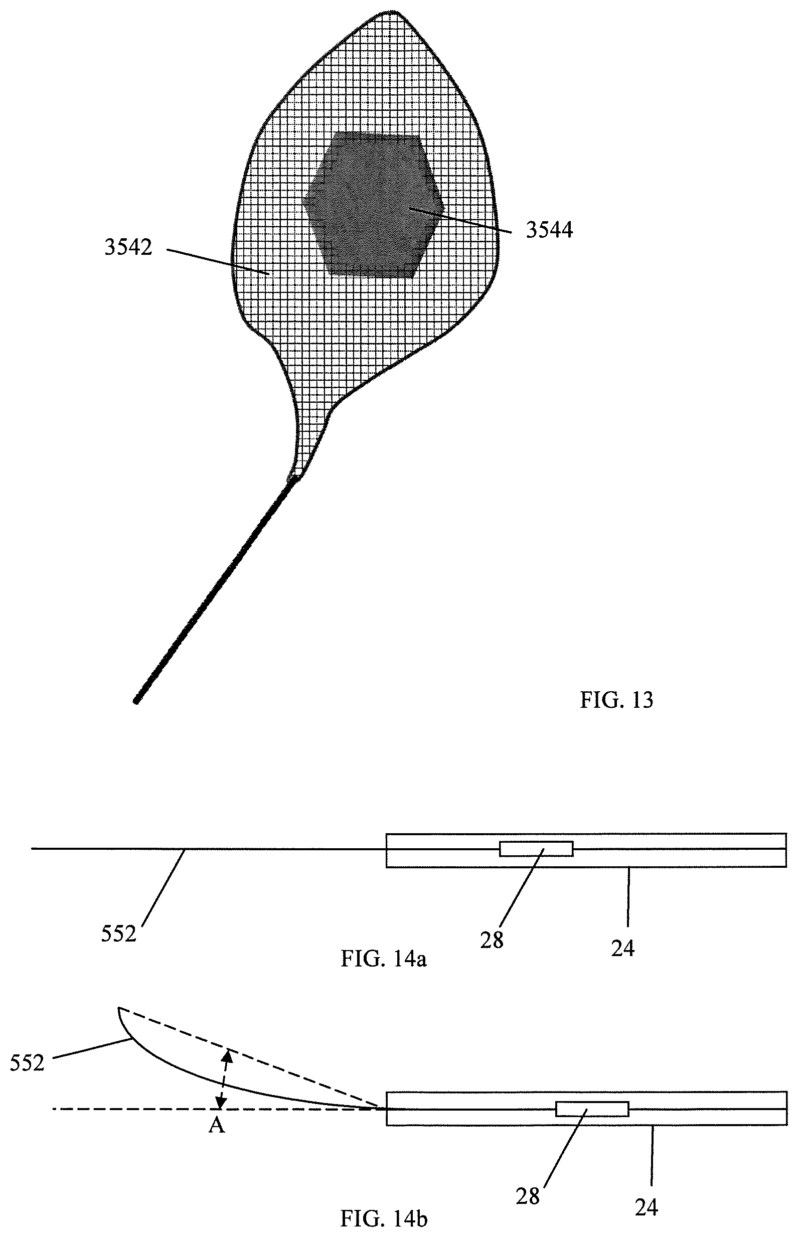
[0056] In the embodiment of FIGS. 11a and 11b, both the first and second net elements 3542, 3544 fully covers the loop. In the embodiment of FIG. 12, the first net element 3542 is made of woven or knitted material. The second net element 3544 is made of plastic film. The first net element 3542 fully covers the loop. The second net element 3544 is attached the middle portion of the first net element 3542 to add support and strength. In the embodiment of FIG. 13, the middle portion of the first net element 3542 is removed and is replaced with the second net element 3544. A person skilled in the art will also realize that the second net element could also be a woven or knitted material instead of plastic film. Also, the first net element could be plastic film instead of a woven or knitted material. Furthermore, it should be apparent that the second element can be woven, sewn, or welded onto the first net element.
[0057] Another aspect of the present subject matter is to provide a new and inventive loop. Referring to FIGS. 14a and 14b, because of its shape memory nature, the loop 552 is so constructed that the loop 552 remains in a substantial level plane at its deployed position; while the loop 552 substantially flexes towards only one direction when the loop 552 is actuated from its deployed position towards its stored position. Person skilled in the art could understand that the loop 552 flexes towards one direction when the loop 552 is at its deployed position. In some embodiment, the loop flexes in a curved fashion. In some other embodiments in FIGS. 15a and 15b, the loop 552 with at least one memory bend flexes towards one direction when the loop 552 is at its deployed position. In some embodiments in FIGS. 14a, 14b, 15a, and 15b, the loop 552 is configured to flex at an angle A of about 20 to 60 degrees. In some other embodiments in FIGS. 14a, 14b, 15a, and 15b, the loop 552 is configured to flex at an angle A of about 30 to 35 degrees.
[0058] In some embodiments, the loop 552 is rotatable with the rotatable link and the rotatable actuating body 18 described above. Depending on the position of the object retrieved, the loop 552 could rotate to a desired angle to flex up or down to achieve a desired result. In some embodiments, the loop 552 or the net is colored or coded at certain areas to remind the operator that which direction the loop 552 flexes. In one embodiment, at least part of the loop 552 is made of memory materials, such as nitinol or other suitable wire.
[0059] Another aspect of the present subject matter is to provide an improved second end of the tubular member. Referring to FIGS. 16a and 16b, in some embodiments, the second end 627 of the tubular member 624 is enlarged. In some embodiments, the second end 627 of the tubular member 624 is flared. This aides in packing the net element into the tubular member during the retraction.
[0060] In some embodiments, the inside surface 628 of the distal portion of the tubular member 624 is smooth and atraumatic. In some embodiments, the second end 627 of the tubular member 624 is an atraumatic tip. This helps to reduce the chances of the net elements from catching or tearing on the distal opening of the tubular member during the retraction. In some embodiments, the outside surface of the distal portion of the tubular member 624 is smooth and atraumatic.
[0061] Another aspect of the present subject matter is to provide a new and inventive arm. The device further comprises at least one arm. The arm has a distal end and a proximal end. The distal end is securely attached to the loop. In some embodiments, the distal end is securely attached to the proximal portion of the loop. A person skilled in the art could understand that the attachment could be welding, gluing, tying, or otherwise known attachment mechanisms.
[0062] In some embodiments in FIGS. 17a and 17b, the device comprises two arms 790. The distal end of each of the arms 790 is securely attached to the proximal portion of the loop 752. The proximal end of each of the arms 790 is attached to the handle 718. The link 734 is shorter than the arms 790 and has a dead stop (not shown) in the handle 718. When the finger ring 720 is actuated about 1/2 way, the link 734 and the arms 790 move together to push the loop to its deployed position. As such, the net has a pouch volume and capacity. When the finger ring 720 is actuated further than about 1/2 way, the link 734 is fixed and the arms 790 are allowed to push out further. The arms 790 force the loop 752 to an expended position. As such, the loop 752 flexes perpendicular to the axis of the tubular member. This causes the net element to stretch tight like a tennis racket. This could help in removal of polyps and/or food debris and also could help scoop and/or move items into a better capture position.
[0063] A person skilled in the art should understand that the endoscopic device described in the present subject matter is not necessary to comprise the support assembly (including the base and the elongated tubular member) and/or the transmitting assembly (including the handle and the link). A handle may be formed by or connected to the proximal end of the loop.
[0064] While several embodiments of the invention have been illustrated and described in considerable detail, the present invention is not to be considered limited to the precise construction disclosed. Various adaptations, modifications and uses of the invention may occur to those skilled in the arts to which the invention relates. It is the intention to cover all such adaptations, modifications and uses falling within the scope or spirit of the claims filed herewith.
* * * * *
D00000
D00001
D00002
D00003
D00004
D00005
D00006
D00007
D00008
D00009
D00010
D00011
D00012
XML
uspto.report is an independent third-party trademark research tool that is not affiliated, endorsed, or sponsored by the United States Patent and Trademark Office (USPTO) or any other governmental organization. The information provided by uspto.report is based on publicly available data at the time of writing and is intended for informational purposes only.
While we strive to provide accurate and up-to-date information, we do not guarantee the accuracy, completeness, reliability, or suitability of the information displayed on this site. The use of this site is at your own risk. Any reliance you place on such information is therefore strictly at your own risk.
All official trademark data, including owner information, should be verified by visiting the official USPTO website at www.uspto.gov. This site is not intended to replace professional legal advice and should not be used as a substitute for consulting with a legal professional who is knowledgeable about trademark law.