Thermally Conductive Insert Element For Electronic Unit
KORTA; Jakub ; et al.
U.S. patent application number 16/747097 was filed with the patent office on 2020-07-23 for thermally conductive insert element for electronic unit. The applicant listed for this patent is APTIV TECHNOLOGIES LIMITED. Invention is credited to Marcel FRUEND, Klaus KAUFMANN, Jakub KORTA.
| Application Number | 20200236811 16/747097 |
| Document ID | 20200236811 / US20200236811 |
| Family ID | 65138943 |
| Filed Date | 2020-07-23 |
| Patent Application | download [pdf] |


| United States Patent Application | 20200236811 |
| Kind Code | A1 |
| KORTA; Jakub ; et al. | July 23, 2020 |
THERMALLY CONDUCTIVE INSERT ELEMENT FOR ELECTRONIC UNIT
Abstract
Electronic unit comprises an housing comprising a top cover; a printed circuit board mounted inside the housing and comprising at least a first heating source element on the top layer of the printed circuit board; the top cover comprises at least a first opening; the electronic unit comprises at least a first thermally conductive insert element distinct from the housing and extending from its top extremity arranged around the first opening, to its bottom extremity in thermal contact with the first heating source element such that heating dissipation of the first heating source element is allowed; fixing means configured to entirely fix the top extremity of the first thermally conductive insert element with the top cover around the first opening.
| Inventors: | KORTA; Jakub; (Krakow, PL) ; FRUEND; Marcel; (Remscheid, DE) ; KAUFMANN; Klaus; (Wuppertal, DE) | ||||||||||
| Applicant: |
|
||||||||||
|---|---|---|---|---|---|---|---|---|---|---|---|
| Family ID: | 65138943 | ||||||||||
| Appl. No.: | 16/747097 | ||||||||||
| Filed: | January 20, 2020 |
| Current U.S. Class: | 1/1 |
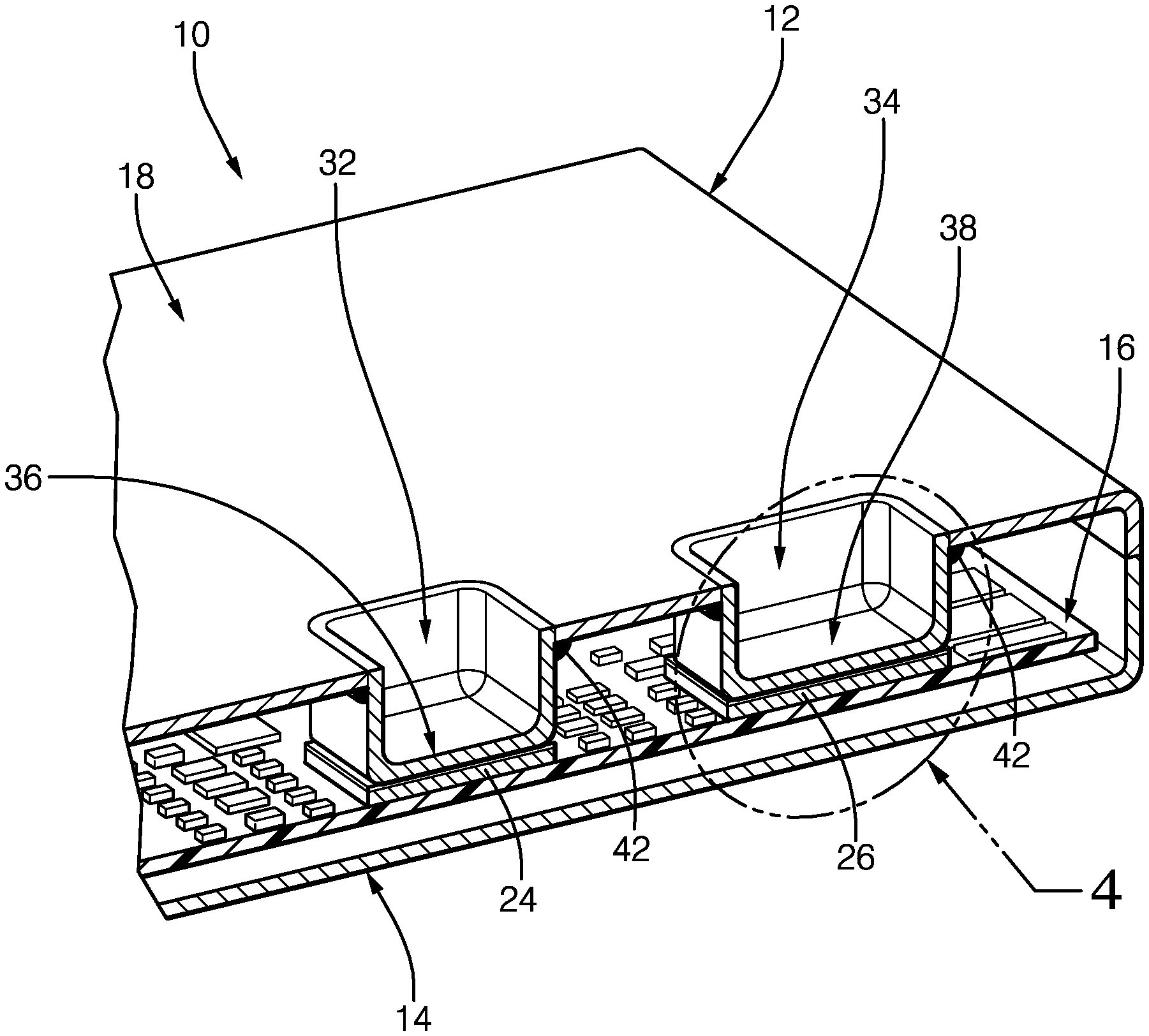
| Current CPC Class: | H05K 7/20418 20130101; H05K 7/20445 20130101; H05K 5/069 20130101; H05K 7/20854 20130101; H05K 7/20254 20130101 |
| International Class: | H05K 7/20 20060101 H05K007/20; H05K 5/06 20060101 H05K005/06 |
Foreign Application Data
| Date | Code | Application Number |
|---|---|---|
| Jan 21, 2019 | EP | 19152913.0 |
Claims
1. An electronic unit, comprising a housing comprising a top cover, the top cover including at least a first opening; a printed circuit board mounted inside the housing and comprising at least a first heating source element on a top layer of the printed circuit board; a first thermally conductive insert element distinct from the housing and extending from a top extremity arranged around the first opening, to a bottom extremity in thermal contact with the first heating source element such that heat dissipation of the first heating source element is allowed; and fixing means configured to entirely fix the top extremity of the first thermally conductive insert element with the top cover around the first opening.
2. Electronic unit according to claim 1, wherein the first thermal conductive insert element comprises a blind cavity extending from the top extremity entirely fixed around the first opening, to the bottom extremity in thermal contact with the first heating source element.
3. Electronic unit according to claim 1, wherein the first thermally conductive insert element has a thermal conductivity greater than a thermal conductivity of the top cover.
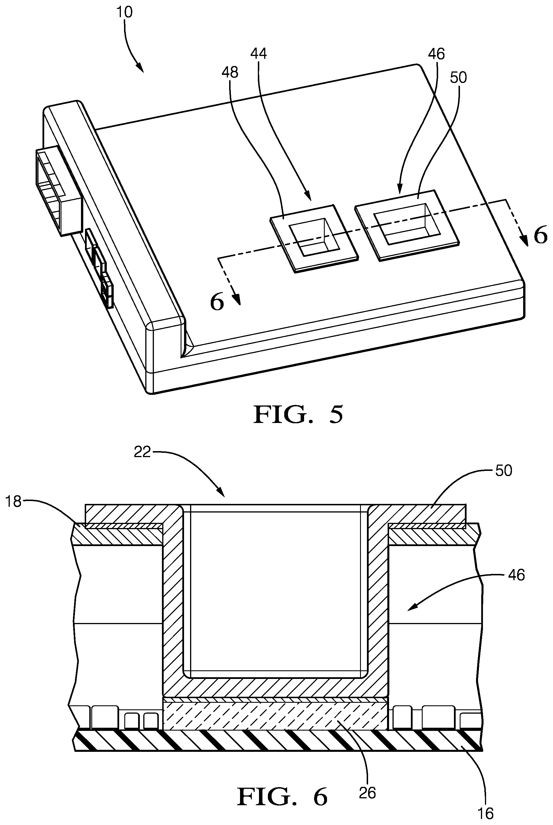
4. Electronic unit according to claim 1, wherein the fixing means are watertight fixing means around the first opening.
5. Electronic unit according to claim 1, wherein the top extremity of the first thermally conductive insert element comprises a flange arranged around the top extremity and fixed with the top cover around the first opening.
6. Electronic unit according to claim 5, wherein the top cover comprises a thickness reduction area all around the first opening and establishing a reduction in thickness equal to or greater than a thickness of the flange so that the flange does not protrude from the top surface of the top cover.
7. Electronic unit according to claim 1, wherein the top cover is made of a liquid coolant cold plate, the top cover comprising a coolant liquid inlet, a coolant liquid outlet, and liquid coolant wall guides configured to convey liquid coolant from the coolant liquid inlet to the first thermally conductive insert element and from the first thermally conductive insert element to the coolant liquid outlet.
8. Electronic unit according to claim 1, wherein the housing comprises a top wall having at least one other opening; the top cover being arranged onto the top extremity; the first thermally conductive insert element being arranged through the other opening.
9. Electronic unit according to claim 8, wherein the top extremity is made of plastic material.
10. Electronic unit according to claim 1, wherein the first thermally conductive insert element and the top cover are made of metallic material.
11. Electronic unit according to claim 10, wherein the first thermally conductive insert element is made of a copper alloy material; and the top cover is made of an aluminum alloy material.
12. Electronic unit according to claim 1, wherein the fixing means comprise an adhesive paste joint.
13. Electronic unit according to claim 10, wherein the fixing means comprising a brazed joint.
14. Electronic unit according to claim 1, wherein the printed circuit board comprises a second heating source element on the top layer of the printed circuit board; the top cover comprises a second opening; the electronic unit comprises a second thermally conductive insert element distinct from the housing and extending from a top extremity arranged around the second opening, to a bottom extremity in thermal contact with the second heating source element such that heat dissipation of the second heating source element is allowed; and said second thermally conductive insert element comprises a second thermal conductivity different than a first thermal conductivity of the first thermally conductive insert element.
15. Electronic unit according to claim 14, wherein the second thermally conductive insert element is made of a silver material.
Description
CROSS REFERENCE TO RELATED APPLICATIONS
[0001] This application claims priority to European Patent Application No. 19152913.0, filed on Jan. 21, 2019.
TECHNICAL FIELD OF THE INVENTION
[0002] The invention relates to electronic unit arranged with thermally conductive insert element for optimized heat dissipation from printed circuit board of the electronic unit.
BACKGROUND OF THE INVENTION
[0003] Typical enclosure for automotive electronics unit is designed for protecting fragile devices from unwanted mechanical loads, dust and humidity. For high efficiency and high power devices which generate significant amounts of thermal energy, housing is also used to enable heat removal allowing the devices to operate within safe temperature limits.
[0004] Generally, in case of die casted housing, heat dissipation is frequently obtained through conduction via the so-called pedestals, which are housing geometrical features allowing for establishing thermal joints between heat sources and housing walls. In case of high heat fluxes generate by electronic devices, complex structures, such has water cooling systems, are implemented in addition with the heat conduction obtained with the die casted housing.
[0005] It is therefore important to propose a new solution to solve these problems.
SUMMARY OF THE INVENTION
[0006] According to the invention, an electronic unit comprises an housing comprising a top cover, a printed circuit board mounted inside the housing and comprising at least a first heating source element arranged on the top layer of the printed circuit board. The top cover comprises at least a first opening and the electronic unit comprises at least a first thermally conductive insert element distinct from the housing and extending from its top extremity arranged around the first opening, to its bottom extremity in thermal contact with the first heating source element such that heating dissipation of the first heating source element is allowed, i.e. such that increased heat dissipation through conduction from the heat source element is possible. The electronic unit comprises fixing means configured to entirely fix the top extremity of the first thermally conductive insert element with the top cover around the first opening.
[0007] The first thermal conductive insert element may comprise a blind cavity extending from its opened top extremity entirely fixed around the first opening, to its bottom wall extremity in thermal contact with the first heating source element. The first thermally conductive insert element may have a thermal conductivity greater than the top cover. The fixing means may be watertight fixing means around the first opening.
[0008] The top extremity of the first thermally conductive insert element may comprise a flange arranged around the top extremity and fixed with the top cover around the first opening. The top cover may comprise a thickness reduction area all around to first opening corresponding to the thickness of the flange, the flange being arranged onto the reduced thickness area such that the surface area of the top cover comprising the flange is a flat surface. The thickness reduction may also be greater than the thickness of the flange such that the flange does not protrude on the top cover.
[0009] The top cover may be made of a liquid coolant cold plate, the top cover comprising a coolant liquid inlet, a coolant liquid outlet, and liquid coolant wall guides configured to convey the coolant liquid from the coolant liquid inlet to the first thermally conductive insert element and from the first thermally conductive insert element to the coolant liquid outlet.
[0010] The housing may comprise a top wall having at least one another opening; the top cover being arranged onto the top wall; the first thermally conductive insert element being arranged through the another opening. The top wall may be made of plastic material. The first thermally conductive insert element and the top cover may be made of metallic material, preferably, the first thermally conductive insert element may be made of cooper alloy material and the top cover may be made of an aluminum alloy material. The fixing means may comprise a brazed joint or the fixing means may comprise an adhesive paste joint especially when the housing is not made of metallic material.
[0011] The printed circuit board may comprise a second heating source element on the top layer of the printed circuit board; the top cover may comprise a second opening such that the electronic unit may comprise a second thermally conductive insert element distinct from the housing and extending from its top extremity arranged around the second opening, to its bottom extremity in thermal contact with the second heating source element such that heating dissipation of the second heating source element is allowed. The second thermally conductive insert element may comprise a thermal conductivity different to the first thermally conductive insert element. The second thermally conductive insert element may be made of silver material.
BRIEF DESCRIPTION OF THE DRAWING
[0012] Other features, objects and advantages of the invention will become apparent from reading the detailed description that follows, and the attached drawing, given by way of example and in which:
[0013] FIG. 1 is a schematic perspective view of the electronic unit without the thermally conductive insert elements according to one embodiment of the invention.
[0014] FIG. 2 is a schematic perspective view of the electronic unit of FIG. 1 arranged with the thermally conductive insert elements according to the invention.
[0015] FIG. 3 is an axial cut view according to plan 3-3 of FIG. 2.
[0016] FIG. 4 is zoom view of the circled area 4 of FIG. 3.
[0017] FIG. 5 is a schematic perspective view of the electronic unit with thermally conductive insert elements according to another embodiment of the invention.
[0018] FIG. 6 is an axial cut view of one thermally conductive insert element according to plan 6-6 of FIG. 2.
[0019] FIG. 7 is an alternative embodiment of FIG. 6.
[0020] FIG. 8 is a schematic perspective view of the electronic unit arranged with a cold plate comprising thermally conductive insert elements according to another embodiment of the invention.
[0021] FIG. 9 is a top perspective view of the cold plate of FIG. 8.
[0022] FIG. 10 is a bottom perspective view of the cold plate of FIG. 8.
DETAILED DESCRIPTION
[0023] According to FIG. 1, an electronic unit 10 is shown. The electronic unit 10 may be an electronic control unit for car or any kind of electronic unit 10, said electronic unit 10 comprises a housing 12. The housing 12 comprises a bottom wall 14 on which a printed circuit board 16 is arranged and a top wall or a top cover 18 that comprises a first opening 20 and a second opening 22 or a first cut-out and a second cut-out. The first opening 20 and the second opening 22 are opened square shape and are respectively arranged above a first heating source element 24 and a second heating source element 26, both heating source elements 24, 26 being arranged on the top layer of the printed circuit board 16.
[0024] An heating source element 24, 26 in the sense of the present disclosure relates to an electronic component that may generate heat during operation, or to any conductive layout pattern as copper track pattern, that also may generate heat when a current is flowing through said pattern.
[0025] According to FIG. 2 and FIG. 3 the electronic unit 10 comprises a first thermally conductive insert element 28, or thermally conductive pedestal, and a second thermally conductive insert element 30, both thermally conductive insert element being distinct from the housing 12. The first thermally conductive insert element 28 and the second thermally conductive element 30 cooperate mechanically respectively with the first opening 20 and the second opening 22 of the top cover 18, and respectively with the first heating source element 24 and the second heating source element 26 such that heating dissipation of the first heating source element 24 and the heating dissipation of the second heating source element 26 are allowed.
[0026] As each thermally conductive insert element 28, 30 are distinct from the housing 12, they may have thermal conductivity different than the housing 12. Generally, the present description provides the advantage of using standard housing 12 material such as plastic or aluminum while the thermally conductive insert elements 28, 30 comprise greater thermal conductivity than the housing 12. Both thermally conductive insert elements 28, 30 may have the same thermal conductivity or different thermal conductivity. As non-limiting example, both thermally conductive insert elements 28, 30 may be made of copper alloy, or if one of the two heating source element 24, 26 needs better heat dissipation, the thermally conductive insert element 28 relative to said heating source element 24 may be made of silver.
[0027] According to the embodiment shown in FIG. 2 and FIG. 3, each thermally conductive insert element 28, 30 comprises a blind cavity 32, 34 or a blind hole extending from its opened top extremity entirely fixed around its associated opening 20, 22, to its bottom wall extremity 36, 38 in thermal contact with the its associated heating source element 24, 26.
[0028] According to FIG. 4, one embodiment of the arrangement of the second thermally conductive insert element 30 is shown. Arrangement of the first thermally conductive insert element 28 may be similar.
[0029] The top layer of the printed circuit board 16 comprises one electronic component as the second heating source element 26. Said electronic component may be as a non-limiting examples, a microcontroller or a solid state power switch. The bottom wall extremity 38 of the second thermally conductive insert element 30 is in thermal contact with the second heating source element 26. More particularly, the second heating source element 26 is in thermal contact with the second thermally conductive insert element 30 by means of a thermal interface material 40 as thermal paste arranged on the top surface of the second heating source element 26. Alternatively, the bottom wall extremity 38 of the second thermally conductive insert element 30 may be in direct thermal contact with the top surface of the second heating source element 26, i.e. without thermal interface material such that heat transfer is less optimized.
[0030] The opened top extremity of the second thermally conductive insert element 30 is arranged inside the second opening 22 and comprises fixing means 42 cooperating with the around inside of the second opening 22 of the top cover 18 such that watertight is guaranteed between the second thermally conductive insert element 30 and the top cover 18. In other words, globally, the fixing means 42 are configured to entirely fix the top extremity of a thermally conductive insert element 28, 30 with the top cover 18 around an opening 20, 22 of the top cover 18.
[0031] Generally, the fixing means 42 comprise an adhesive paste joint that suits with most of the housing 12 materials that have to be fixed with the thermally conductive insert element 28, 30.
[0032] In case of the top cover 18 is made of metallic material, and the first thermally conductive insert element 28 and the second thermally conductive insert element 30 are also made of metallic material, said first and second thermally conductive insert elements 28, 30 may be respectively brazed with the around inside of the first opening 20 and the second opening 22 of the top cover 18 such that a brazed join is formed between each thermally conductive insert element 28, 30 and the top cover 18 providing watertight effect. As alternatives, the opened top extremity of the thermally conductive insert may be brazed with the around of the opening on top of the top cover 18 or on the bottom side of the top cover 18.
[0033] According to FIG. 5, the top cover 18 of the electronic unit 10 comprises a variant of the first thermally conductive insert element 28 and the second thermally conductive insert element 30. The top cover 18 is equipped with a third thermally conductive insert element 44 and a fourth thermally conductive insert element 46 that differ from the first thermally conductive insert element 28 and the second thermally conductive insert element 30 by comprising a flange 48, 50 around their top extremity. The flange 48, 50 of each thermally conductive insert element 44, 46 improves the fixing strength of the third thermally conductive insert element 44 and of the fourth thermally conductive insert element 46 with the top cover 18. Additionally, in case of a metallic top cover 18, said flanges 48, 50 improve respectively the heating transfer from the third thermally conductive insert element 44 and from the fourth thermally conductive insert element 46 to the metallic top cover 18.
[0034] According to FIG. 5 and FIG. 6, the flange 50 is fixed around the second opening 22 of the top cover 18, on the top surface, or external surface, of the top cover 18. Alternatively, the flange 50 may be fixed on the bottom surface, or internal surface, of the top cover 18. The flange 50 may be glued to the top cover 18 by the usage of adhesive paste joint. In case of metallic top cover 18, the flange 50 may be brazed with the top cover 18 such that a brazed joint is formed between the flange 50 and the top cover 18.
[0035] According to FIG. 7, the top cover 18 is arranged with the fourth thermally conductive insert element 46. The flange 50 is mounted around the second opening 22, on the top surface of the top cover 18. More particularly, the top cover 18 comprises a thickness reduction area 52 all around to first opening 20. The thickness reduction is equal or greater than the thickness of the flange 50 such that the flange 50 does not protrude on the top surface of the top cover 18. While the thickness reduction is equal to the corresponding thickness of the flange 50, the surface area of the top cover 18 comprising the flange 50 is a flat surface.
[0036] The embodiment shown in FIG. 7 differs from the embodiment of FIG. 5 and FIG. 6 such that the top surface of the top cover 18 wherein the flange 50 is mounted, i.e. the thickness reduction area 52 of the top cover 18 comprising the flange 50, is a flat surface. In that case, the flange 50 of the fourth thermally conductive insert element 46 does not affect the top surface plan of the top cover 18.
[0037] According to FIG. 8, the electronic unit 10 comprises a cold plate 54. The cold plate 54 is arranged on the top surface of the housing 12. According to FIG. 9 and FIG. 10, the mechanical cooperation between the cold plate 54 and the thermally conductive insert elements 44, 46 is similar than the mechanical cooperation between the top cover 18 and the third thermally conductive insert element 44 and the fourth the thermally conductive insert element 46 shown at FIG. 5, FIG. 6 and FIG. 7. In other words, the cold plate 54 comprises two other openings 56, 58 such that the thermally conductive insert elements 44, 46 are fixed in a similar manner than described by the FIGS. 5, 6 and 7.
[0038] Alternatively, the thermally conductive insert elements arranged with the cold plate 54 may be similar that the first thermally conductive insert element 28 and the second thermally conductive insert element 30 as shown at FIG. 2, FIG. 3 and FIG. 4.
[0039] According to FIG. 8, FIG. 9 and FIG. 10, as being fixed to the cold plate 54, when assembled with the electronic unit 10 housing 12, each thermally conductive insert element 44, 46 fixed with the cold plate 54 is arranged through an opening 20, 22 of the top wall of the housing 12 of the electronic unit 10, i.e. an opening 20, 22 of the top cover 18 as defined at FIG. 1. From that embodiment the thermally conductive insert elements 44, 46 are not any more primarily fixed with the housing 12, but they are primarily fixed with the cold plate 54. In order to guaranteed watertight between the cold plate 54 and the opening 20, 22 of the top wall of the housing 12, adhesive paste joint may be added between the cold plate 54 and the top wall of the housing 12.
[0040] According to FIG. 8, FIG. 9 and FIG. 10, the cold plate 54 is more particularly a liquid coolant cold plate 54 comprising a coolant liquid inlet 60 and a coolant liquid outlet 62.
[0041] More particularly, in order to efficiently cool down the thermally conductive insert elements 44, 46, the cold plate 54 comprises liquid coolant wall guides 64, 66, 68, as liquid coolant deflector, configured to convey the liquid coolant from the coolant liquid inlet 60 to each thermally conductive insert element 44, 46, and to convey the liquid coolant from each thermally conductive insert element 44, 46 to the coolant liquid outlet 62.
[0042] Alternatively, each thermally conductive insert element 44, 46 may be attached at their top extremity to a single cold plate to increase their thermal conductivity.
[0043] The invention is not limited to the shape of the openings 20, 22 of the top wall and of the top cover and of the thermally conductive insert elements 28, 30, 44, 46 shown at the FIGS. 2 and 5. Other shape may be also suitable for the invention. In addition, other thermal conductive material than the ones cited in that present description may also be suitable for the thermally conductive insert elements 28, 30, 44, 46. The number of thermally conductive insert elements 28, 30, 44, 46 and their corresponding heating source element 24, 26 may be greater than two.
* * * * *
D00000
D00001
D00002
D00003
D00004
D00005
XML
uspto.report is an independent third-party trademark research tool that is not affiliated, endorsed, or sponsored by the United States Patent and Trademark Office (USPTO) or any other governmental organization. The information provided by uspto.report is based on publicly available data at the time of writing and is intended for informational purposes only.
While we strive to provide accurate and up-to-date information, we do not guarantee the accuracy, completeness, reliability, or suitability of the information displayed on this site. The use of this site is at your own risk. Any reliance you place on such information is therefore strictly at your own risk.
All official trademark data, including owner information, should be verified by visiting the official USPTO website at www.uspto.gov. This site is not intended to replace professional legal advice and should not be used as a substitute for consulting with a legal professional who is knowledgeable about trademark law.