Network Multi-source Inbound Quality Of Service Methods And Systems
Mayya; Ajit Ramachandra ; et al.
U.S. patent application number 16/785628 was filed with the patent office on 2020-07-23 for network multi-source inbound quality of service methods and systems. The applicant listed for this patent is Nicira, Inc.. Invention is credited to Stephen Craig Connors, Ajit Ramachandra Mayya, Sunil Mukundan, Mukamala Swaminathan Srihari, Parag Pritam Thakore, Steven Michael Woo.
| Application Number | 20200235999 16/785628 |
| Document ID | / |
| Family ID | 63791045 |
| Filed Date | 2020-07-23 |


View All Diagrams
| United States Patent Application | 20200235999 |
| Kind Code | A1 |
| Mayya; Ajit Ramachandra ; et al. | July 23, 2020 |
NETWORK MULTI-SOURCE INBOUND QUALITY OF SERVICE METHODS AND SYSTEMS
Abstract
A computerized method useful for implementing a Multi-Source Inbound QoS (Quality of Service) process in a computer network includes the step of calculating a current usage rate of a provider entity. The provider entity is classified by a network traffic priority; implementing a fair sharing policy among a set of provider entities. The method includes the step of adjusting any excess bandwidth among a set of provider entities. The method includes the step of implementing link sharing at a provider-entity level.
| Inventors: | Mayya; Ajit Ramachandra; (Saratoga, CA) ; Thakore; Parag Pritam; (Los Gatos, CA) ; Connors; Stephen Craig; (San Jose, CA) ; Woo; Steven Michael; (Los Altos, CA) ; Mukundan; Sunil; (Chennai, IN) ; Srihari; Mukamala Swaminathan; (Chennai, IN) | ||||||||||
| Applicant: |
|
||||||||||
|---|---|---|---|---|---|---|---|---|---|---|---|
| Family ID: | 63791045 | ||||||||||
| Appl. No.: | 16/785628 | ||||||||||
| Filed: | February 9, 2020 |
Related U.S. Patent Documents
| Application Number | Filing Date | Patent Number | ||
|---|---|---|---|---|
| 15811329 | Nov 13, 2017 | 10574528 | ||
| 16785628 | ||||
| 62457816 | Feb 11, 2017 | |||
| Current U.S. Class: | 1/1 |
| Current CPC Class: | H04L 43/0882 20130101; H04L 41/0896 20130101; H04L 43/0876 20130101 |
| International Class: | H04L 12/24 20060101 H04L012/24; H04L 12/26 20060101 H04L012/26 |
Claims
1-14. (canceled)
15. For wide area network (WAN) comprising a plurality of forwarding nodes, a method for implementing multi-source inbound quality of service (QoS) at an edge first forwarding node that connects a site to the WAN, the method comprising identifying a plurality of usage values for a plurality of other forwarding nodes of the WAN that forward packets to the edge first forwarding node along a shared WAN link; based on the identified usage values, allocating bandwidth to each of the other forwarding nodes; and configuring at least one particular other forwarding node to honor the bandwidth allocated to the particular other forwarding node.
16. The method of claim 15, wherein identifying the plurality of usage values comprises receiving, from each of the other forwarding nodes, at least one usage value that represents a desired quantity of network traffic that the other forwarding node expects to send to the first forwarding node.
17. The method of claim 15, wherein allocating bandwidth comprises allocating bandwidth for different types of traffics that are associated with different priority levels.
18. The method of claim 17, wherein allocating bandwidth for different traffic types comprises allocating first and second bandwidth levels for first and second traffic types to at least one of the other forwarding nodes.
19. The method of claim 18, wherein identifying the plurality of usage values comprises receiving, from each of the other forwarding nodes, at least one usage value that represents a desired quantity of network traffic that the other forwarding node expects to send to the first forwarding node; the other forwarding node that is assigned first and second bandwidth levels for first and second traffic types provides first and second usage values for the first and second traffic types to the first forwarding node.
20. The method of claim 15, wherein the other forwarding nodes comprise a cloud gateway.
21. The method of claim 15, wherein the other forwarding nodes comprise an edge second forwarding node connecting another site to the WAN.
22. The method of claim 21, wherein the sites comprise a branch office of an enterprise and a datacenter the enterprise, or two branch offices of the enterprise.
23. The method of claim 21 further comprising forcing the particular other forwarding node to reduce its transmission rate to a rate that does not exceed the amount of bandwidth allocated to the particular other forwarding node.
24. The method of claim 21, wherein the usage value for each of the other forwarding nodes specifies an amount of bandwidth needed by the other forwarding node to send network traffic to the first forwarding node without dropping any packet.
25. An electronic device comprising: a set of one or more processing units; and a non-transitory machine readable medium storing a program which when executed by at least one of the processing units, implements a multi-source inbound Quality of Service (QoS) process at an edge first forwarding node that connects a site to the WAN, the program comprising a set of instructions for: identifying a plurality of usage values for a plurality of other forwarding nodes of the WAN that forward packets to the edge first forwarding node along a shared WAN link; based on the identified usage values, allocating bandwidth to each of the other forwarding nodes; and configuring at least one particular other forwarding node to honor the bandwidth allocated to the particular other forwarding node.
26. The electronic device of claim 25, wherein the set of instructions for identifying the plurality of usage values comprises a set of instructions for receiving, from each of the other forwarding nodes, at least one usage value that represents a desired quantity of network traffic that the other forwarding node expects to send to the first forwarding node.
27. The electronic device of claim 25, wherein the set of instructions for allocating bandwidth comprises a set of instructions for allocating bandwidth for different types of traffics that are associated with different priority levels.
28. The electronic device of claim 27, wherein the set of instructions for allocating bandwidth for different traffic types comprises a set of instructions for allocating first and second bandwidth levels for first and second traffic types to at least one of the other forwarding nodes.
29. The electronic device of claim 28, wherein the set of instructions for identifying the plurality of usage values comprises a set of instructions for receiving, from each of the other forwarding nodes, at least one usage value that represents a desired quantity of network traffic that the other forwarding node expects to send to the first forwarding node; the other forwarding node that is assigned first and second bandwidth levels for first and second traffic types provides first and second usage values for the first and second traffic types to the first forwarding node.
30. The electronic device of claim 25, wherein the other forwarding nodes comprise a cloud gateway.
31. The electronic device of claim 25, wherein the other forwarding nodes comprise an edge second forwarding node connecting another site to the WAN.
32. The electronic device of claim 31, wherein the sites comprise a branch office of an enterprise and a datacenter the enterprise, or two branch offices of the enterprise.
33. The electronic device of claim 31, wherein the program further comprises a set of instructions for forcing the particular other forwarding node to reduce its transmission rate to a rate that does not exceed the amount of bandwidth allocated to the particular other forwarding node.
34. The electronic device of claim 31, wherein the usage value for each of the other forwarding nodes specifies an amount of bandwidth needed by the other forwarding node to send network traffic to the first forwarding node without dropping any packet.
Description
CROSS-REFERENCE TO RELATED APPLICATIONS
[0001] This application claims priority to U.S. Provisional Application No. 62/457,816, titled and METHOD AND SYSTEM OF OVERLAY FLOW CONTROL filed on 11 Feb. 2017. This provisional application is incorporated by reference in its entirety. These applications are incorporated by reference in their entirety.
FIELD OF THE INVENTION
[0002] This application relates generally to computer networking, and more specifically to a system, article of manufacture and method Of Multi-Source Inbound QoS (quality of service).
DESCRIPTION OF THE RELATED ART
[0003] Employees working in branch offices of an Enterprises typically need to access resources that are located in another branch office. In some cases, these are located in the Enterprise Data Center, which is a central location for resources. Access to these resources is typically obtained by using a site-to-site VPN, which establishes a secure connection over a public network (e.g. the Internet, etc.). There may be dedicated computer equipment in the branch office, the other branch office and/or Data Center which establishes and maintains the secure connection. These types of site-to-site VPNs can be setup one at a time and can be resource intensive to set up and maintain.
[0004] It is typical in deployments that a VCMP endpoint (e.g. a receiver) (e.g. VCMP tunnel initiator or responder; can be a VCE or VCG) can receive traffic from multiple VCMP sources (e.g. providers henceforth), such as VCMP endpoints and/or a host in the Internet. In these scenarios, the sum of all the receiver traffic on the receiver can be greater than the rated receiver capacity on the link. This can be because the providers are independent of each other. The provider can also be agnostic of the total unused receiver capacity at the receiver. This can lead to receiver oversubscription at the receiver which may lead to adverse impact on application performance.
SUMMARY
[0005] A computerized method useful for implementing a Multi-Source Inbound QoS (Quality of Service) process in a computer network includes the step of calculating a current usage rate of a provider entity. The provider entity is classified by a network traffic priority; implementing a fair sharing policy among a set of provider entities. The method includes the step of adjusting any excess bandwidth among a set of provider entities. The method includes the step of implementing link sharing at a provider-entity level.
BRIEF DESCRIPTION OF THE DRAWINGS
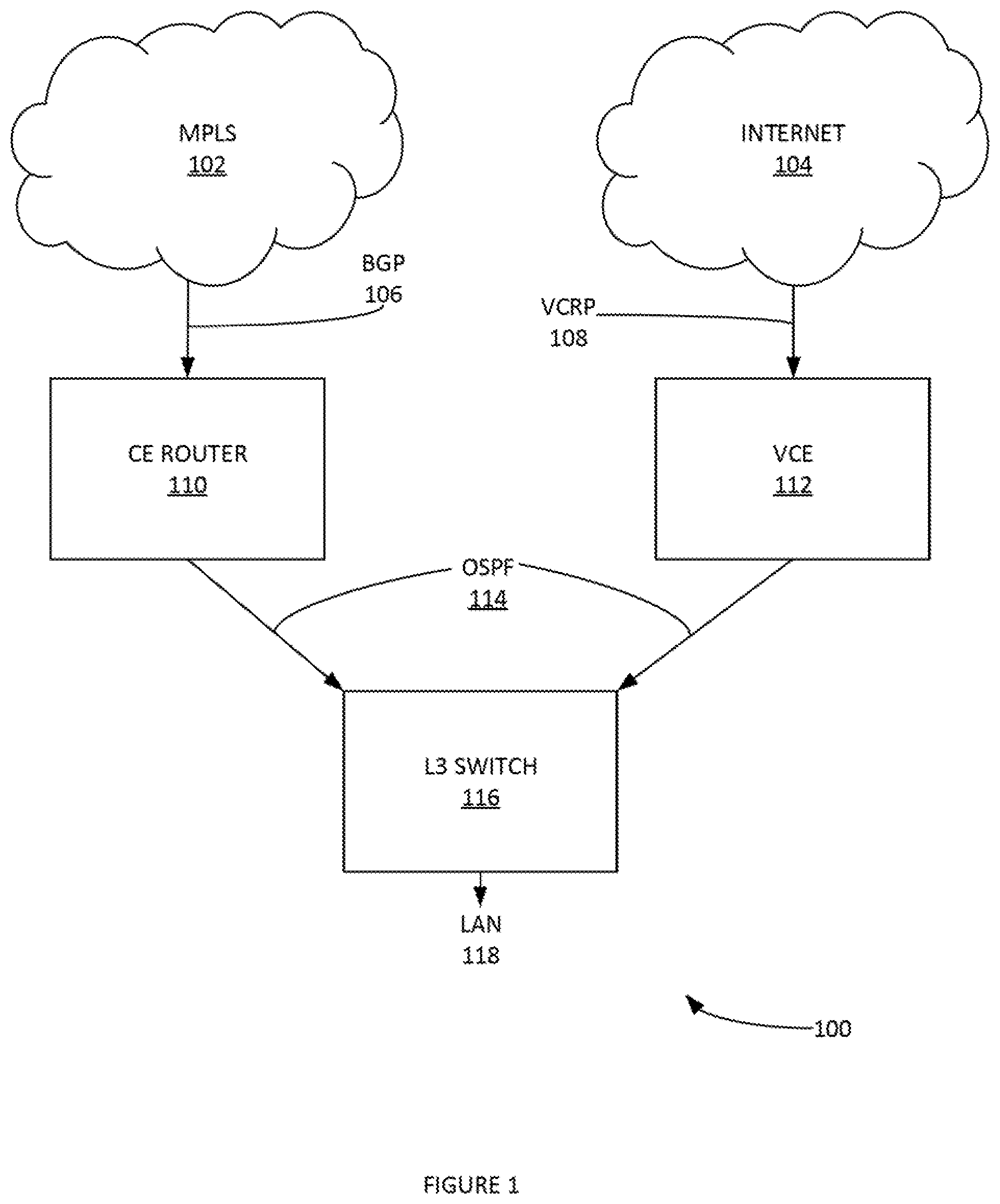
[0006] FIG. 1 illustrates an example network for implementing Overlay Flow Control, according to some embodiments.
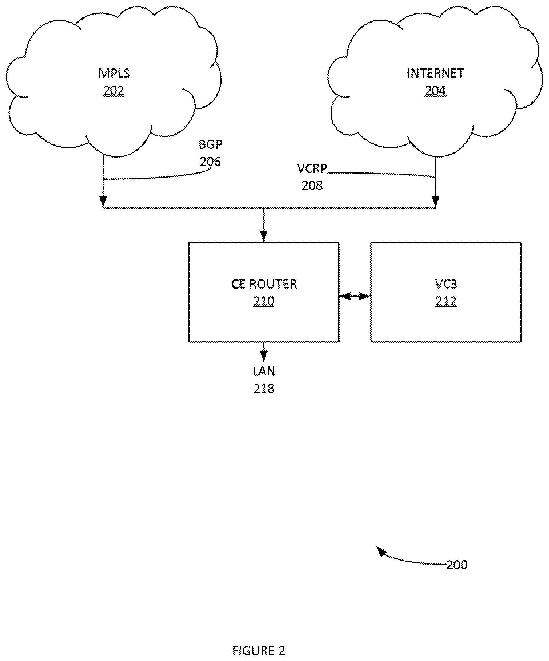
[0007] FIG. 2 illustrates another example network for implementing Overlay Flow Control, according to some embodiments.
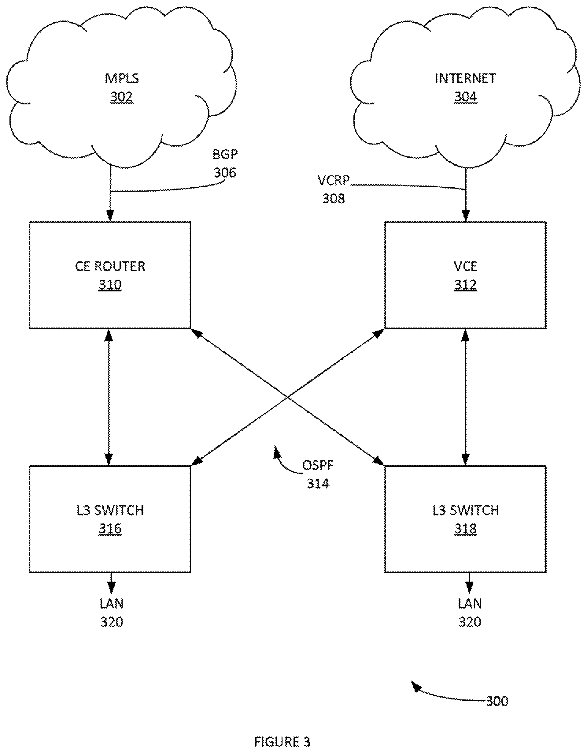
[0008] FIG. 3 illustrates another example network for implementing Overlay Flow Control, according to some embodiments.
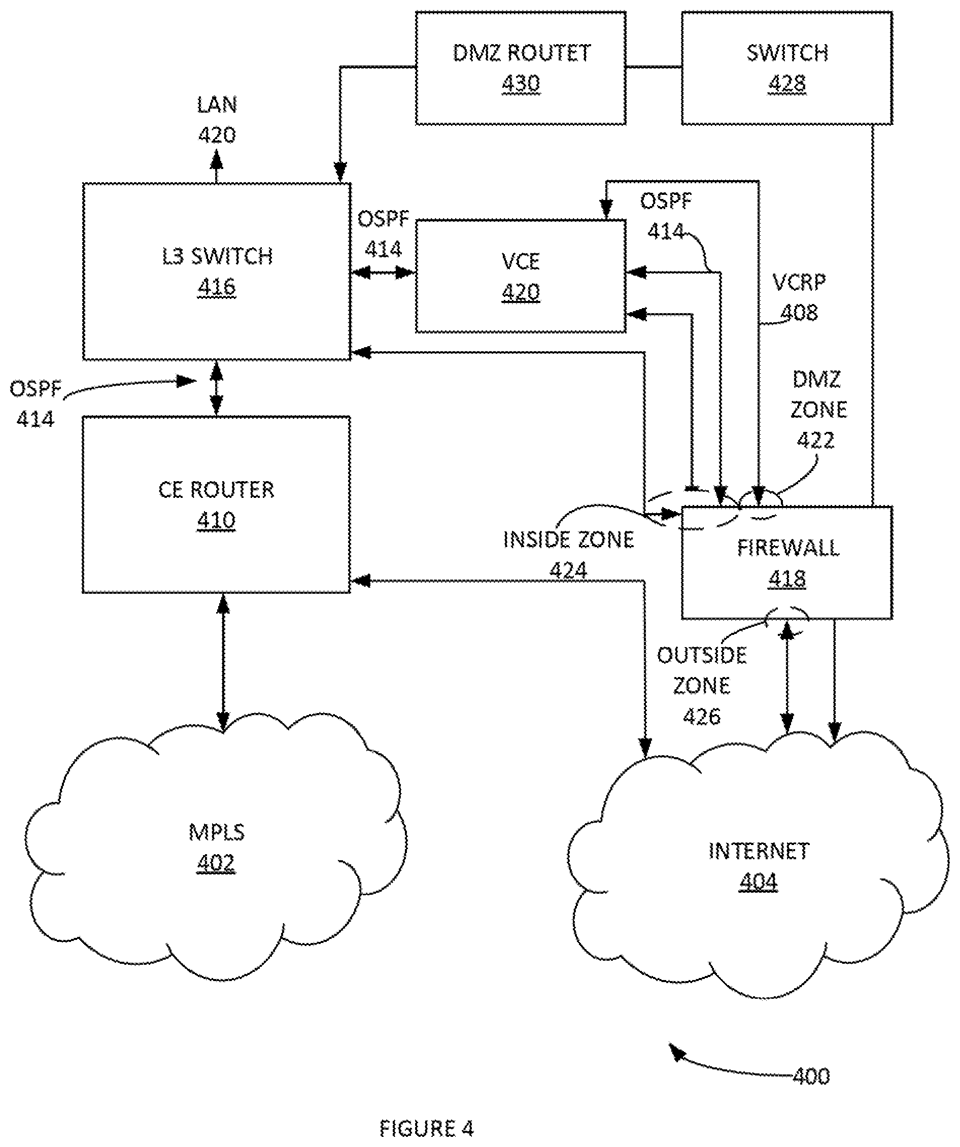
[0009] FIG. 4 illustrates another example network for implementing Overlay Flow Control, according to some embodiments.
[0010] FIG. 5 illustrates an example topology of two datacenters can be configured as edge-to-edge VPN hubs, according to some embodiments.
[0011] FIGS. 6-7 illustrates example failover behaviours for preferred and non-preferred routes, according to some embodiments.
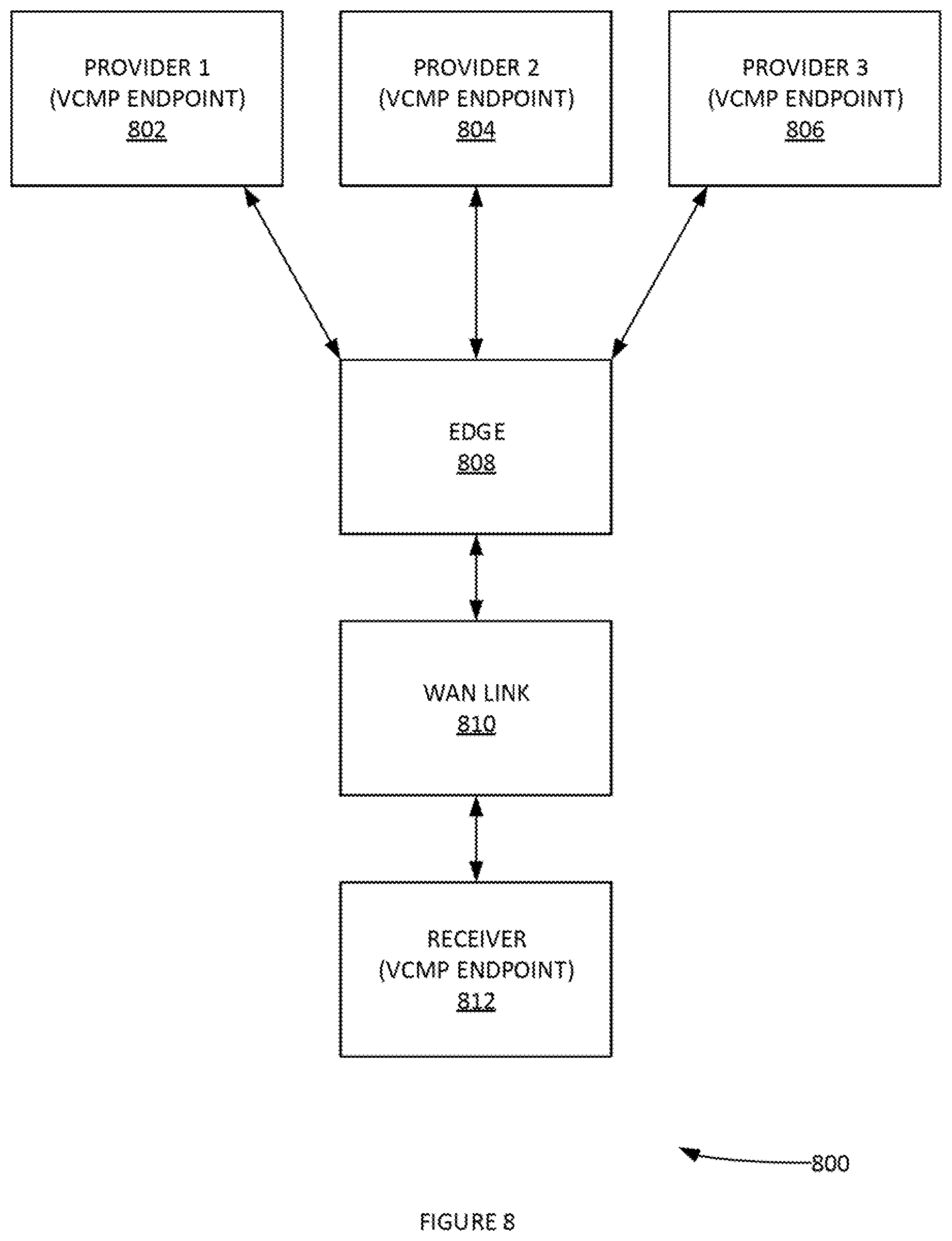
[0012] FIG. 8 illustrates an example system for implementing Multi-Source Inbound QoS (Quality of Service), according to some embodiments.
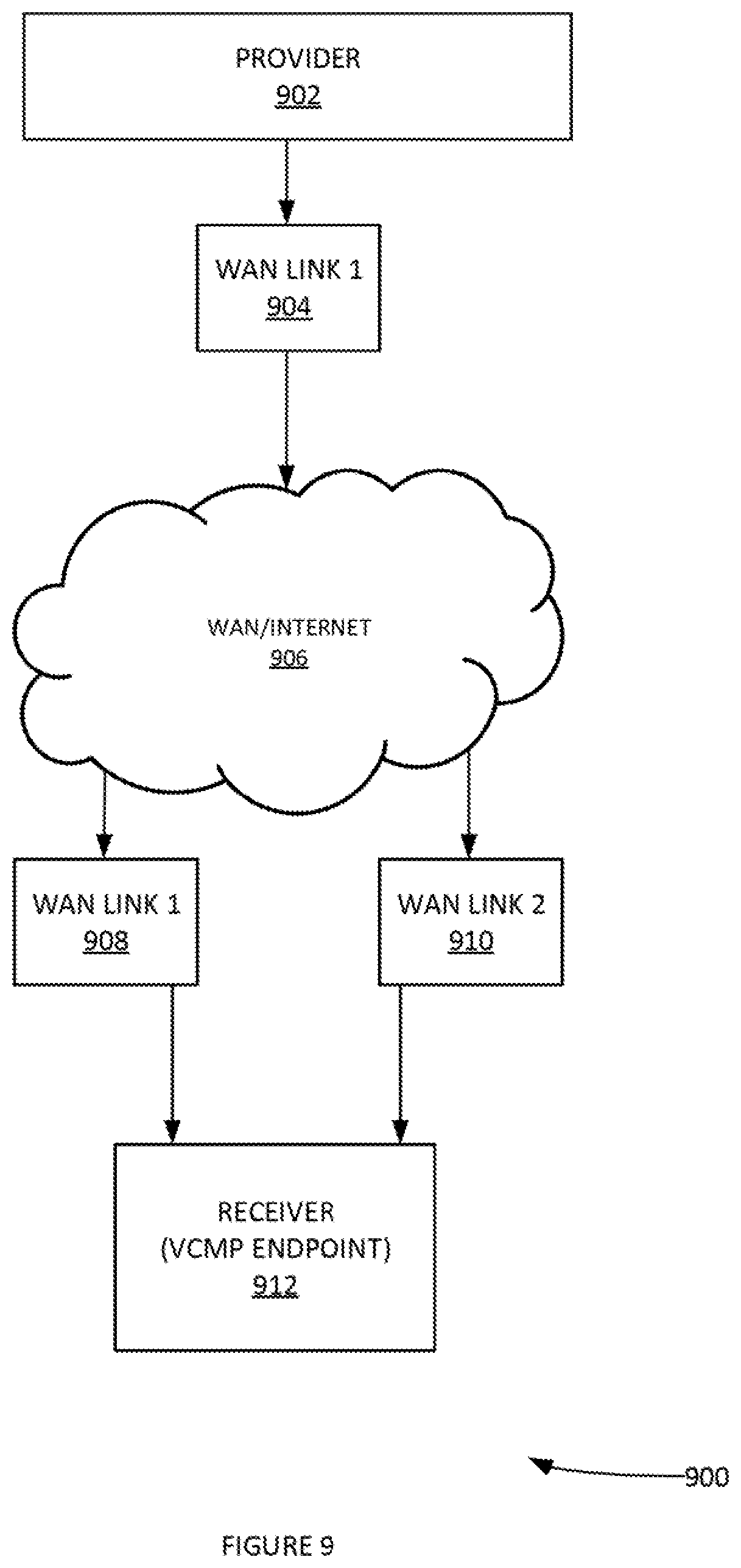
[0013] FIG. 9 illustrates a system with a many-to-one link on a provider (e.g. Cloud Gateways and one arm Partner Gateways), according to some embodiments.
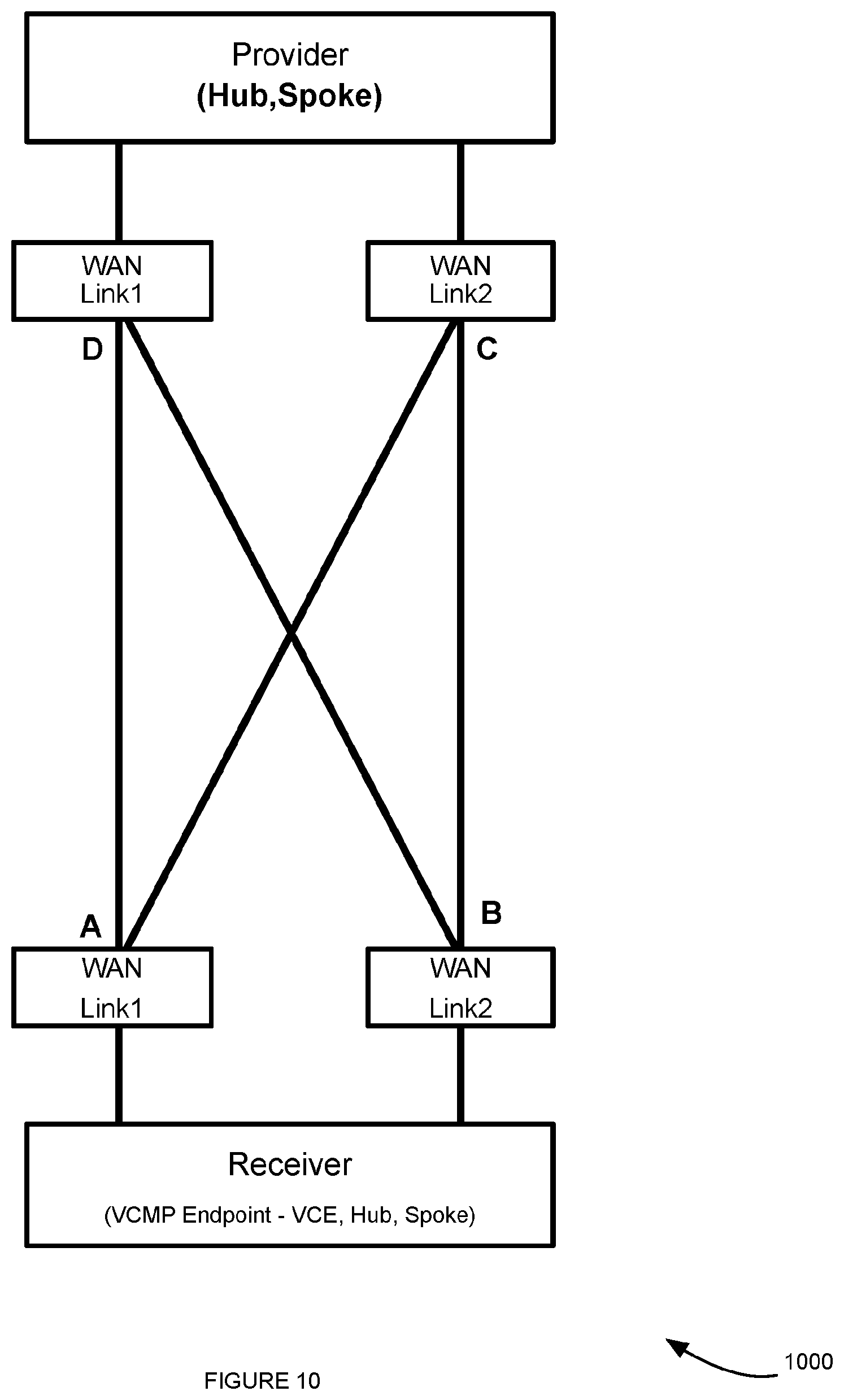
[0014] FIG. 10 illustrates a system with many-to-many links on the provider (e.g. with a hub as a provider).
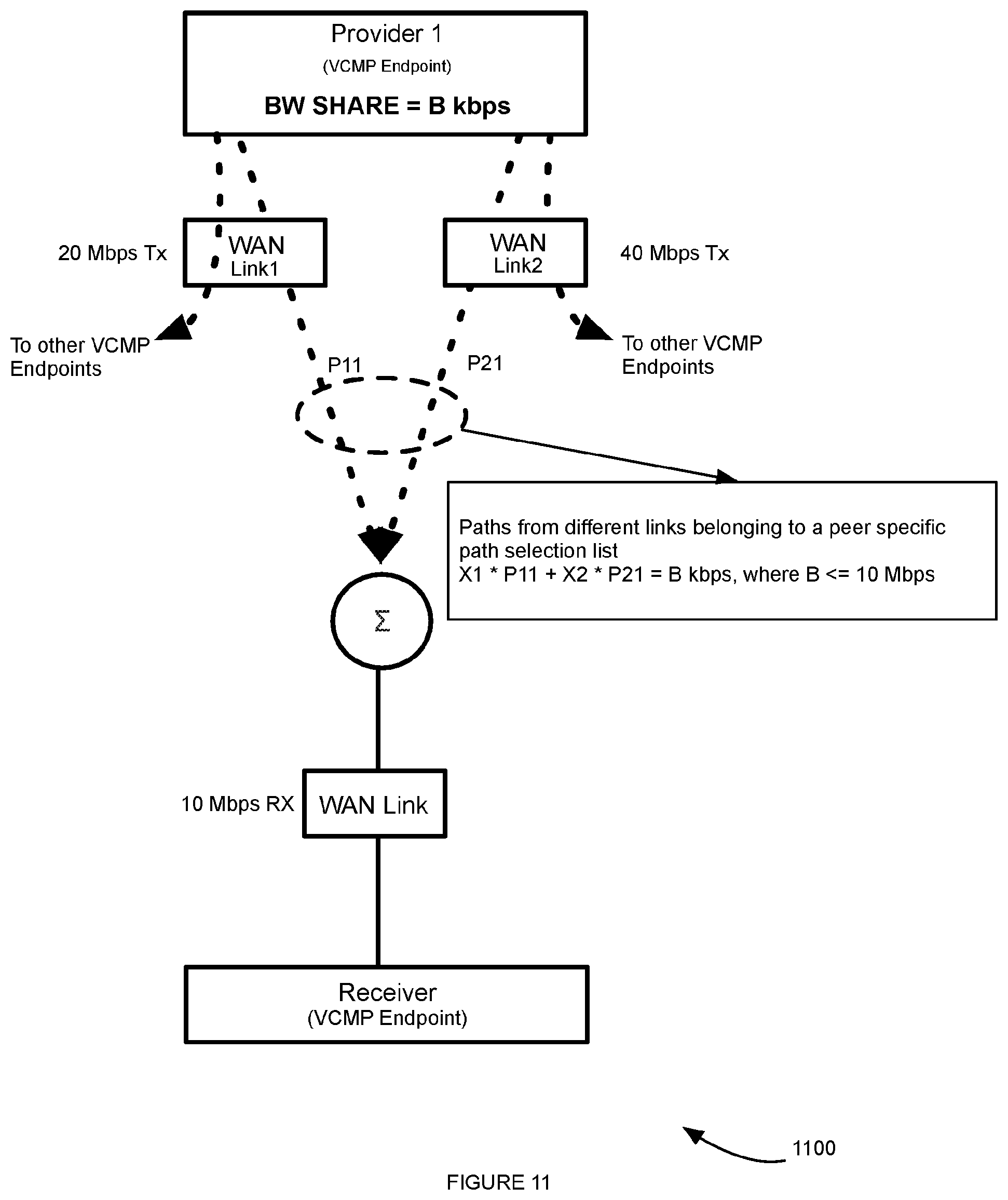
[0015] FIG. 11 illustrates an example system with endpoints as Hubs, according to some embodiments.
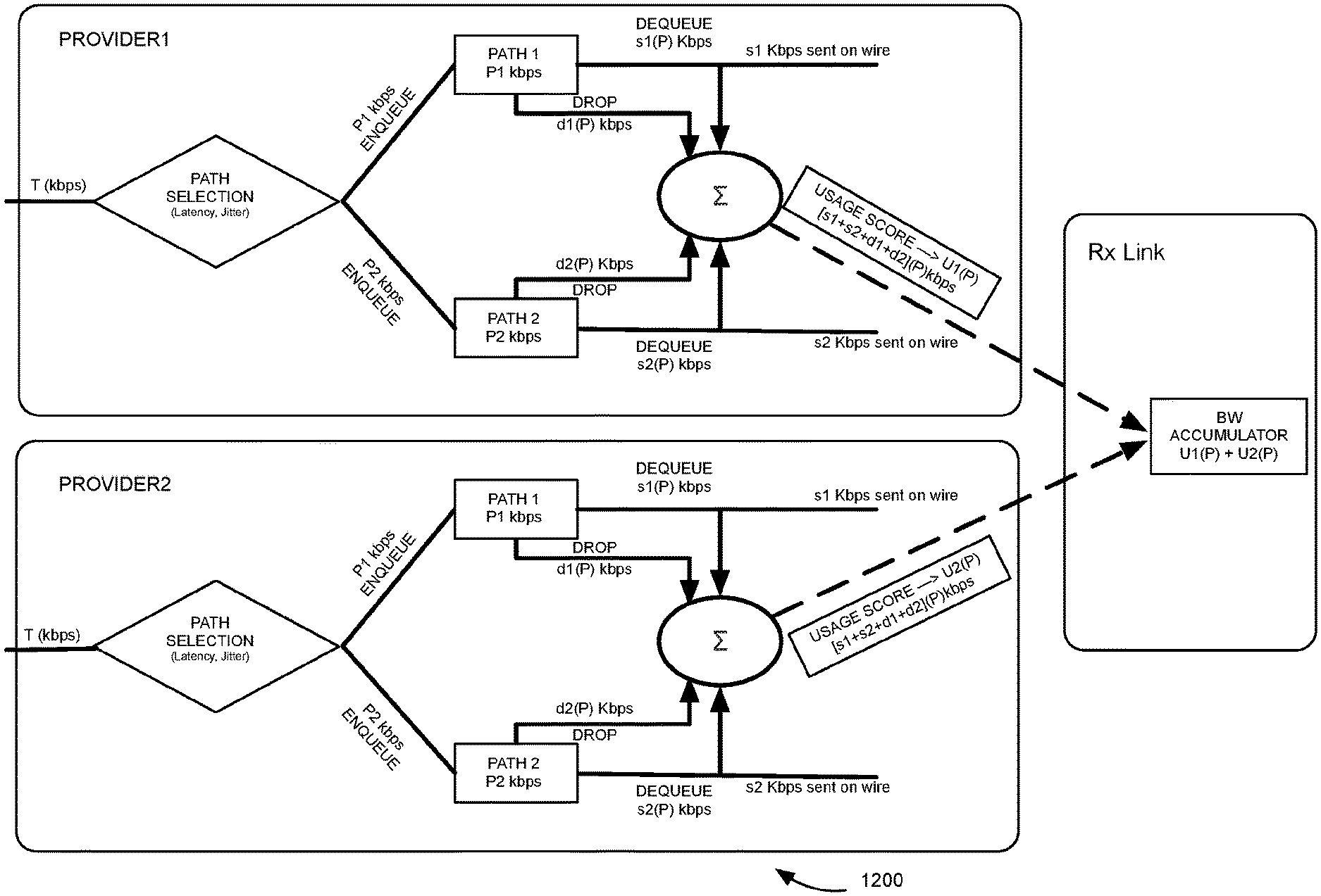
[0016] FIG. 12 illustrates an example process for calculating usage, according to some embodiments.
[0017] FIG. 13 illustrates an example screenshot of an algorithm for calculating a usage score, according to some embodiments.
[0018] FIG. 14 depicts an exemplary computing system that can be configured to perform any one of the processes provided herein.
[0019] FIG. 15 illustrates an example Multi-Source Inbound QoS algorithm, according to some embodiments.
[0020] The Figures described above are a representative set, and are not exhaustive with respect to embodying the invention.
DESCRIPTION
[0021] Disclosed are a system, method, and article of manufacture for overlay flow control. The following description is presented to enable a person of ordinary skill in the art to make and use the various embodiments. Descriptions of specific devices, techniques, and applications are provided only as examples. Various modifications to the examples described herein can be readily apparent to those of ordinary skill in the art, and the general principles defined herein may be applied to other examples and applications without departing from the spirit and scope of the various embodiments.
[0022] Reference throughout this specification to "one embodiment," "an embodiment," `one example,` or similar language means that a particular feature, structure, or characteristic described in connection with the embodiment is included in at least one embodiment of the present invention. Thus, appearances of the phrases "in one embodiment," "in an embodiment," and similar language throughout this specification may, but do not necessarily, all refer to the same embodiment.
[0023] Furthermore, the described features, structures, or characteristics of the invention may be combined in any suitable manner in one or more embodiments. In the following description, numerous specific details are provided, such as examples of programming, software modules, user selections, network transactions, database queries, database structures, hardware modules, hardware circuits, hardware chips, etc., to provide a thorough understanding of embodiments of the invention. One skilled in the relevant art can recognize, however, that the invention may be practiced without one or more of the specific details, or with other methods, components, materials, and so forth. In other instances, well-known structures, materials, or operations are not shown or described in detail to avoid obscuring aspects of the invention.
[0024] The schematic flow chart diagrams included herein are generally set forth as logical flow chart diagrams. As such, the depicted order and labeled steps are indicative of one embodiment of the presented method. Other steps and methods may be conceived that are equivalent in function, logic, or effect to one or more steps, or portions thereof, of the illustrated method. Additionally, the format and symbols employed are provided to explain the logical steps of the method and are understood not to limit the scope of the method. Although various arrow types and line types may be employed in the flow chart diagrams, and they are understood not to limit the scope of the corresponding method. Indeed, some arrows or other connectors may be used to indicate only the logical flow of the method. For instance, an arrow may indicate a waiting or monitoring period of unspecified duration between enumerated steps of the depicted method. Additionally, the order in which a particular method occurs may or may not strictly adhere to the order of the corresponding steps shown.
Definitions
[0025] Example definitions for some embodiments are now provided.
[0026] Border Gateway Protocol (BGP) can be a standardized exterior gateway protocol designed to exchange routing and reachability information among autonomous systems (AS) on the Internet.
[0027] Cloud computing can involve deploying groups of remote servers and/or software networks that allow centralized data storage and online access to computer services or resources. These groups of remote serves and/or software networks can be a collection of remote computing services.
[0028] CE router (customer edge router) can be a router located on the customer premises that provides an Ethernet interface between the customer's LAN and the provider's core network. CE routers can be a component in an MPLS architecture.
[0029] Customer-premises equipment (CPE) can be any terminal and associated equipment located at a subscriber's premises and connected with a carrier's telecommunication channel at the demarcation point.
[0030] Edge device can be a device that provides an entry point into enterprise or service provider core networks. An edge device can be software running in a virtual machine (VM) located in a branch office and/or customer premises.
[0031] Firewall can be a network security system that monitors and controls the incoming and outgoing network traffic based on predetermined security rules.
[0032] Flow can be a grouping of packets that match a five (5) tuple which is a combination of Source IP Address (SIP), Destination IP Address (DIP), L4 Source Port (SPORT) and L4 Destination Port (DPORT) and the L4 protocol (PROTO).
[0033] Forward error correction (FEC) (e.g. channel coding) can be a technique used for controlling errors in data transmission over unreliable or noisy communication channels.
[0034] Deep learning can be a type of machine learning based on a set of algorithms that attempt to model high-level abstractions in data by using model architectures, with complex structures or otherwise, composed of multiple non-linear transformations
[0035] Deep Packet Inspection (DPI) can be the ability to analyze the different layers of a packet on the network.
[0036] Gateway can be a node (e.g. a router) on a computer network that serves as an access point to another network.
[0037] Internet Protocol Security (IPsec) can be a protocol suite for securing Internet Protocol (IP) communications by authenticating and encrypting each IP packet of a communication session.
[0038] Multiprotocol Label Switching (MPLS) can be a mechanism in telecommunications networks that directs data from one network node to the next based on short path labels rather than long network addresses, thus avoiding complex lookups in a routing table.
[0039] Orchestrator can include a software component that provides multi-tenant and role based centralized configuration management and visibility.
[0040] Open Shortest Path First (OSPF) can be a routing protocol for Internet Protocol (IP) networks. OSPF ca use a link state routing (LSR) algorithm and falls into the group of interior gateway protocols (IGPs), operating within a single autonomous system (AS).
[0041] Quality of Service (QoS) can include the ability to define a guaranteed set of actions such as routing, resource constraints (e.g. bandwidth, latency etc.).
[0042] Software as a service (SaaS) can be a software licensing and delivery model in which software is licensed on a subscription basis and is centrally hosted.
[0043] Tunneling protocol can allow a network user to access or provide a network service that the underlying network does not support or provide directly.
[0044] Virtual Desktop Infrastructure (VDI) is a desktop-oriented service that hosts user desktop environments on remote servers and/or blade PCs. Users access the desktops over a network using a remote display protocol.
[0045] Virtual private network (VPN) can extend a private network across a public network, such as the Internet. It can enable users to send and receive data across shared or public networks as if their computing devices were directly connected to the private network, and thus benefit from the functionality, security and management policies of the private network.
[0046] Voice over IP (VoIP) can a methodology and group of technologies for the delivery of voice communications and multimedia sessions over Internet Protocol (IP) networks, such as the Internet.
[0047] Additional example definitions are provided herein.
[0048] Examples Systems and Processes of Overlay Flow Control
[0049] In order to integrate into customer environments with minimal configuration required on existing devices, an Edge device and a gateway system can support dynamic routing protocols. In order to facilitate simplified use and management of these dynamic routing protocols such as OSPF. Accordingly, various Overlay Flow Control methods and system can be implemented. These can provide a user a single, simple point of configuration for all routes in a network without requiring changes to the protocol configuration itself.
[0050] FIG. 1 illustrates an example network 100 for implementing Overlay Flow Control, according to some embodiments. Network 100 provides an example topology with a single L3 switch 116 that is connected on the LAN 118 side of an edge device 112 (e.g. a VELOCLOUD.RTM. edge device, etc.). L3 switch 116 can also be connected to a CE router 110. CE router 110 can redistribute an MPLS 102 and/or BGP 106 routes into OSPF 114 routes. In this topology, the edge device can learn routes from the L3 switch 116. Edge device 112 can inject its own routes as well. Network 100 can be communicatively coupled with the Internet 104 utilizing routing protocol 108 (e.g. VELOCLOUD.RTM. routing protocol, etc.). CE router 110 can be a customer edge (CE) router.
[0051] FIG. 2 illustrates another example network 200 for implementing Overlay Flow Control, according to some embodiments. Network 100 provides an example topology where the Internet 204 and MPLS 202 links both terminate on a single router 210. Edge device 212 can be deployed in a `one-arm` configuration attached to CE router 212. The edge device can redistribute an MPLS 102 and/or BGP 106 routes into OSPF 114 routes. In this topology, edge device 212 can learn routes from the L3 switch 116. In this example topology, edge device 212 can learn routes from the CE router 212, as well as injecting its own routes.
[0052] FIG. 3 illustrates another example network 300 for implementing Overlay Flow Control, according to some embodiments. In an example large branch site, an active/active 13 switches 316-318 can communicate routes using OSPF 314 between two upstream devices (e.g. an Edge device) using OSPF 314 and a CE router 310. CE router 310 redistribute MPLS BGP routes 302, 306 into OSPF routes 314. It is noted that network 300 includes the notion of a single WAN link (e.g. MPLS) is accessible via two routed interfaces. In order to support this, a virtual IP address can be provisioned inside the edge and used in OSPF advertisement.
[0053] FIG. 4 illustrates another example network 400 for implementing Overlay Flow Control, according to some embodiments. Network 400 can implement Overlay Flow Control in a datacenter site. A datacenter can have a distinct separation between the MPLS core and DMZ switch. The L3 switch can be talking OSPF and can be used for route learning and injection. The firewall within the DMZ can use routes injected via OSPF (though none may be learned) to ensure that returning Internet traffic is routed symmetrically.
[0054] FIG. 5 illustrates an example topology 500 of two datacenters can be configured as edge-to-edge VPN hubs, according to some embodiments. Example topology 500 can include redundant datacenters which advertise the same subnets with different costs. In this scenario, both datacenters (e.g. a primary datacenter and a backup datacenter, etc.) can be configured as edge-to-edge VPN hubs. As all edges connect directly to each hub, the hubs can also connect directly to each other. Based on a route cost value, network traffic can be steered to the preferred active datacenter.
[0055] The customer can indicate whether routes are preferred (e.g. VELOCLOUD.RTM. Overlay becomes the default path with MPLS as a backup) and/or non-preferred (e.g. where MPLS remains the default path with VELOCLOUD.RTM. Overlay as a backup). The route costs for preferred, non-preferred and/or default routes can be configurable. For example, they can have different defaults based on whether OE1 or OE2 routes are used in the redistribution.
[0056] In one example, a CE Router can advertise an OE2 route. For routes with cost `n` (where `n>1`), it can be advertised with cost `n-1`. For routes with cost `1`, it can be advertised with cost `1` and a link cost `m-1`, where m is the link cost from the L3 Switch/Router to the CE router.
[0057] In another example, CE Router advertises an OE1 route. Take the OE1 route cost as `n`. The link cost can be obtained from the L3 Switch/Router to the CE router as `m`. It can be advertised a route with cost `n-prime` and link cost `m-prime` such that (`n-prime`+`m-prime`)<(`n+m`).
[0058] FIGS. 6-7 illustrates example failover behaviors 600-700 for preferred and non-preferred routes, according to some embodiments. It is noted that though route costs can be calculated for preferred and non-preferred routes (e.g. as provided supra), for simplicity they are presented below as `n` for CE router cost, `n-1` for a preferred route cost and `n+1` for a non-preferred route cost.
[0059] To simplify the visualization and management of routes, they are presented in the Overlay Flow Control table. This table provides an enterprise-wide view of routes, routing adjacencies and preferred exits for each specific route. The preferred exit for any given route can be selected which can result in the routing preferences being automatically updated at each Edge device and advertised to influence routing changes across the network without the customer having to perform any further configuration actions. An edge device can implement the following rules for redistributing VCRP (e.g. a routing protocol) into OSPF. First, an edge device can redistribute VCRP prefixes that belong to various bronze sites as OE1, metric <m> If VCRP route preference is lower than DIRECT (if available) route preference. Else the prefixes are redistributed as OE2, metric <m> where m=low priority. A Direct route preference can be fixed to two-hundred and fifty-six (256). A VCRP route preference lower than 256 can indicate a route as a preferred route otherwise a Direct rout (if available) is preferred. The system can watch out for how CPE's redistribute this prefix into the MPLS cloud. The system can determine if the metric type is preserved by BGP attributes while redistributing into OSPF. The system can determine if the cost is preserved by BGP attributes while redistributing into OSPF.
[0060] Route insertion rules can be implemented. Routes can be inserted into a unified routing table based on the type of VPN profile configured. Hubs can setup direct routes for all VCRP prefixes. Branches can setup direct routes for prefixes via CG and/or VPN-hubs and/or DE2E direct route. For the same prefix, there can be two routes per transit point. This can be because the prefix is advertised by the owner and the hub. A first route can have a next_hop logical ID as transit point and destination logical ID as the owner. A next route can have a next hop logical ID and/or destination logical ID as VPN hub (e.g. not applicable for CG and DE2E).
[0061] A first example use case can include provisioning an edge device inside a datacenter location that previously did not contain one. In this example, Hub1 can be inserted into the Datacenter site as shown in the picture with a routed interface connected to L3 switch and the other WAN link connected to the Internet. The leg connecting L3 switch and Hub1 can have OSPF enabled. Hub1 can advertise default route 0.0.0.0/0 (originate-default) with metric 0 to L3 switch. This can allow Hub1 to take over Internet traffic sourced by subnets connected to L3 switch. Route H can have been learned as intra-area route (O). Route S can have been learned as external type route (e.g. OEx). Route H and Route S can be added to OSPF view and are sent to VCO for GNDT sync up. Hub1 can be marked as owner of prefix `H` and VCO responds to Hub1 with advertise flag set to True for prefix `H`. Sites that advertise intra-area (O) or inter-area (IA) routes can be marked as owner of the routes in GNDT and can be allowed to advertise the routes to VCG. VCO can respond to Hub1 with advertise flag set to False for prefix `S` as `S` is an external-route and requires administrator's intervention. Hub1 can advertises route `H` to VCG through VCRP.
[0062] In a second use-case example, a Bronze site can be brought online, t is noted that the as a prerequisite, the Datacenter are already be online. A Bronzel site (e.g. a simple branch office site with only Internet connections and no MPLS or dynamic routing protocols such as OSPF in use at the site) can be provisioned and connected to VCG through an Internet link. Bronzel site can advertise route `B` to VCG through VCRP. VCG can be a reflector that reflects route `B` to Hub1 with Bronzel site as next hop and can reflect route `H` to Bronzel site with Hub1 site as next hop.
[0063] In a third use-case example, a Silver site (e.g. a branch office site containing a hybrid of MPLS and internet WAN links as well as an L3 device which Is learning and advertising routes via OSPF) can be brought online. It is noted that the as a prerequisite, the Datacenter and associated Bronze site are already be online. Silver1 site can be stood up and connected to VCG through an Internet link. Silver1 site can learn routes `H` and `B` through VCG and install the learned sites into a unified route table. For example, Silver1 site can learn routes `S` as an intra-area and routes `H` and `B` as external routes (e.g. from L3 switch). Routes `S`, `H`, and `B` can be added to OSPF View and are communicated to VCO for GNDT synchronization. VCO responds with advertise flag set to `True` for prefix `S` but set to False for prefix `H` and `B` Silver1 can advertise `S` to other branches via VCG over VCRP.
[0064] In a fourth use-case example, a Legacy site route advertisement can be implemented. It is noted that the as a prerequisite, the Datacenter and associated Bronze and Silver sites are already online. Legacy site route `L` can be learned by Hub1 site and Silver1 site as external route (e.g. OEx). Hub1 and Silver1 can communicate route `L` to VCO for GNDT synchronization. Hub1 can be chosen as owner for the external route `L`. (e.g. without administrator intervention). Hub1 can advertise route `L` to other branches via VCG over VCRP. This can enable connectivity between legacy site `L` and bronze1 site `B`.
[0065] Various examples of hybrid sites distributing routes learned through VCRP into OSPF are now discussed. In a first example, a hybrid site on receiving route `R` over VCRP can redistribute `R` to L3 switch as external route based on various criteria. VELOCLOUD.RTM. (B2B) can be set as preferred. Route `R` can be revoked if it was installed with metric type OE2. Route `R` can be redistributed with metric type OE1, metric `M`=1; etc. Accordingly, the L3 switch can be programmed with route `R` pointing to VCE. Additionally, OE1 can provide the adjacent routers to add cost to route `R` as the routes get redistributed further and thus may not impact the route priority for this route `R` on other receiving sites. In one example, Silver1 can install route `R` with metric 1, metric type OE1. This route `R` can be installed as the high priority route on adjacent L3 router(s). However, when this route `R` reaches another hybrid site. For example, Datacenter site can see that the route `R` with metric >one (1). Accordingly, this does not affect the route `R` on adjacent 13 routers of Datacenter site that would be pointing to Datacenter site as next hop.
[0066] A Direct criterion can be set as preferred when it is available. In one example, route `R` can be revoked if it was installed with metric type OE1, metric `M`=one (1). Route `R` can be redistributed with metric type OE2, metric `M`=cost of `R`+<low_prio_offset>. <low_prio_offset> can be some value that installs the route as low priority route. The value can be updated based on lab experiment.
[0067] Hybrid site redistributing `R` to L3 switch can enable connectivity between `R` and `B` over VELOCLOUD.RTM. B2B overlay. The VELOCLOUD B2B Overlay is the VELOCLOUD Edge and Gateway multipath system that was defined in the original patent providing multipath VPN connectivity between sites. Additionally, it allows connectivity between legacy sites `L` and `B` over private links and VELOCLOUD B2B overlay.
[0068] It should be noted that though OSPF has been used for Illustration purposes supra, the overlay flow control table supports other dynamic routing protocols. for instance, if the protocol is BGP instead of OSPF, metric `M` can be automatically calculated using MED or local preference.
[0069] Multi-Source Inbound QoS
[0070] FIG. 8 illustrates an example system 800 for implementing Multi-Source Inbound QoS (Quality of Service), according to some embodiments. In system 800, the total receiver capacity of the WAN link 810 at the receiver can be ten (10) Mbps. Provider 1 802 and Provider 2 804 can be VCMP (VELOCLOUD Multipath Protocol) endpoints. Provider 3 806 ca be a host on the internet. In the present example, Provider 1 802 can attempt to transmit 10 Mbps to the Edge 808. Provider 2 804 can attempt to transmit 10 Mbps to the Edge 808. Provider 3 806 can attempt to transmit 10 Mbps to the Edge 808. Edge 808 can only accept 10 Mbps of the traffic but the aggregated receiver traffic from the providers 802-806 is greater than 10 Mbps leading to application degradation and general link quality degradation.
[0071] It is further noted that a provider's QoS class-based queueing may not be honoured at the receiver. For example, Provider 1802 can be sending `High` priority `Realtime` class traffic and Provider 2 804 can be sending `Low` priority `Bulk` traffic. However, there is no guarantee that the High/Realtime traffic may be prioritized over the Low/Bulk traffic.
[0072] Multi-Source Inbound QoS is now discussed. Multi-source Inbound QoS addresses the problems discussed supra by letting the receiver assess the volume and priority of the receiver traffic and then assign the transmission bandwidth to the providers 802-806.
[0073] Various example topologies for implementing Multi-Source Inbound QoS are now provided. In some example, two classes of topologies can provide a unique in the way a provider `shares` the allocated bandwidth. The topologies may differ in the number of links on which a VCMP paths can be terminated on a provider which in turn changes the link scheduling hierarchy and the caps that are configured at the nodes. FIGS. 9-11 illustrate example versions of this topology. FIG. 9 illustrates a system 900 with a many-to-one link on a provider (e.g. Cloud Gateways and one arm Partner Gateways), according to some embodiments. System 900 can include paths from receivers. FIG. 10 illustrates a system 1000 with many-to-many links on the provider (e.g. with a hub as a provider). System 1000 can include paths from receivers.
[0074] FIG. 11 illustrates an example system 1100 with endpoints as Hubs, according to some embodiments. It is noted that supported topologies can enable for VCMP tunnels on multiple links. In these case, this allocated share can be adjusted across paths without affecting multi-path link selection for that receiver. For Internet hosts as providers, a policer can be implemented at the receiver that can force the host to reduce its transmission rate to the capacity allocated for such providers.
[0075] Additional Exemplary Computer Architecture and Systems
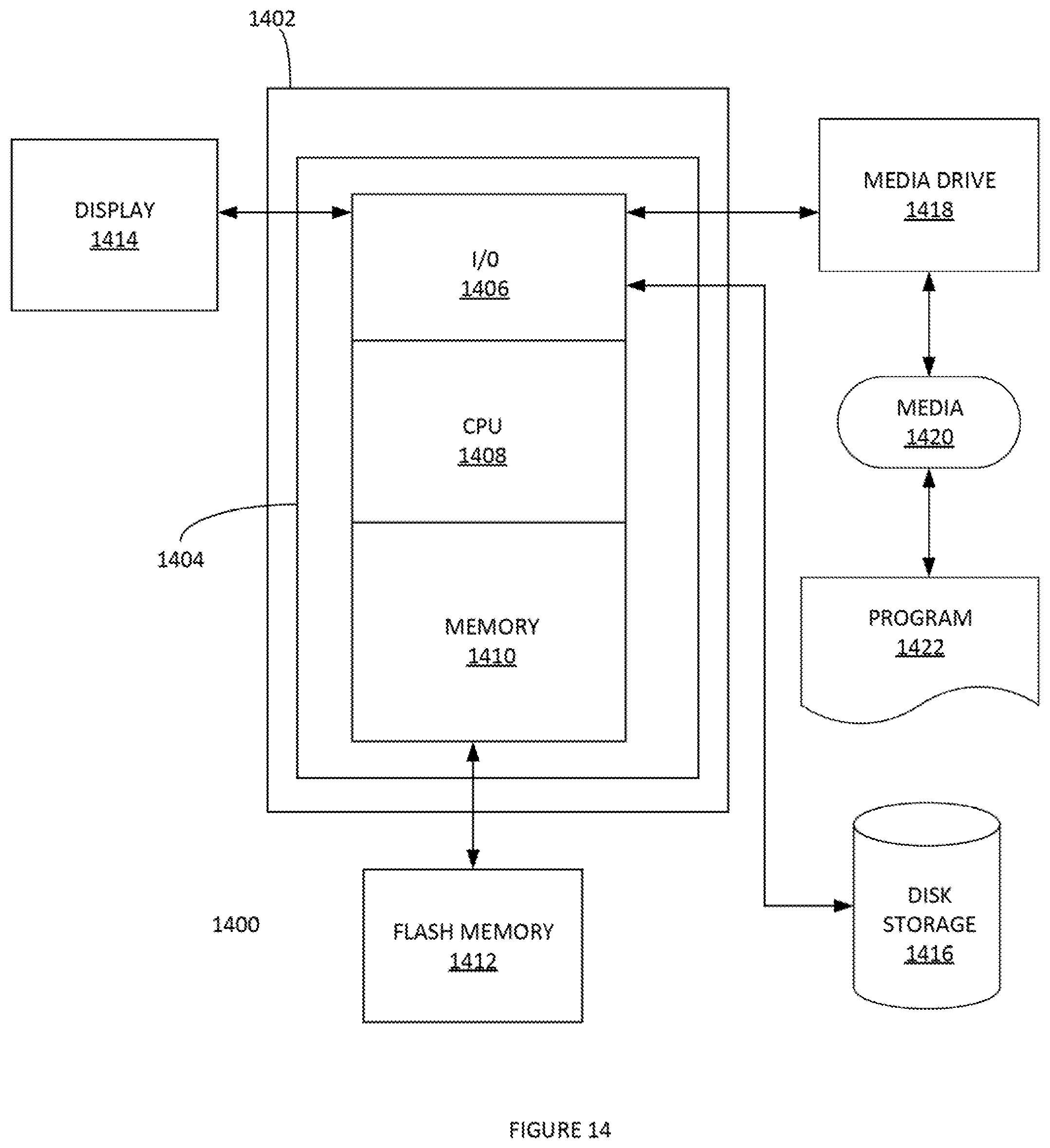
[0076] FIG. 14 depicts an exemplary computing system 1400 that can be configured to perform any one of the processes provided herein. In this context, computing system 1400 may include, for example, a processor, memory, storage, and I/O devices (e.g., monitor, keyboard, disk drive, Internet connection, etc.). However, computing system 1400 may include circuitry or other specialized hardware for carrying out some or all aspects of the processes. In some operational settings, computing system 1400 may be configured as a system that includes one or more units, each of which is configured to carry out some aspects of the processes either in software, hardware, or some combination thereof.
[0077] FIG. 14 depicts computing system 1400 with a number of components that may be used to perform any of the processes described herein. The main system 1402 includes a motherboard 1404 having an I/O section 1406, one or more central processing units (CPU) 1408, and a memory section 1410, which may have a flash memory card 1412 related to it. The I/O section 1406 can be connected to a display 1414, a keyboard and/or other user input (not shown), a disk storage unit 1416, and a media drive unit 1418. The media drive unit 1418 can read/write a computer-readable medium 1420, which can contain programs 1422 and/or data. Computing system 1400 can include a web browser. Moreover, it is noted that computing system 1400 can be configured to include additional systems in order to fulfill various functionalities. Computing system 1400 can communicate with other computing devices based on various computer communication protocols such a Wi-Fi, Bluetooth.RTM. (and/or other standards for exchanging data over short distances includes those using short-wavelength radio transmissions), USB, Ethernet, cellular, an ultrasonic local area communication protocol, etc.
[0078] Multi-Source Inbound QoS
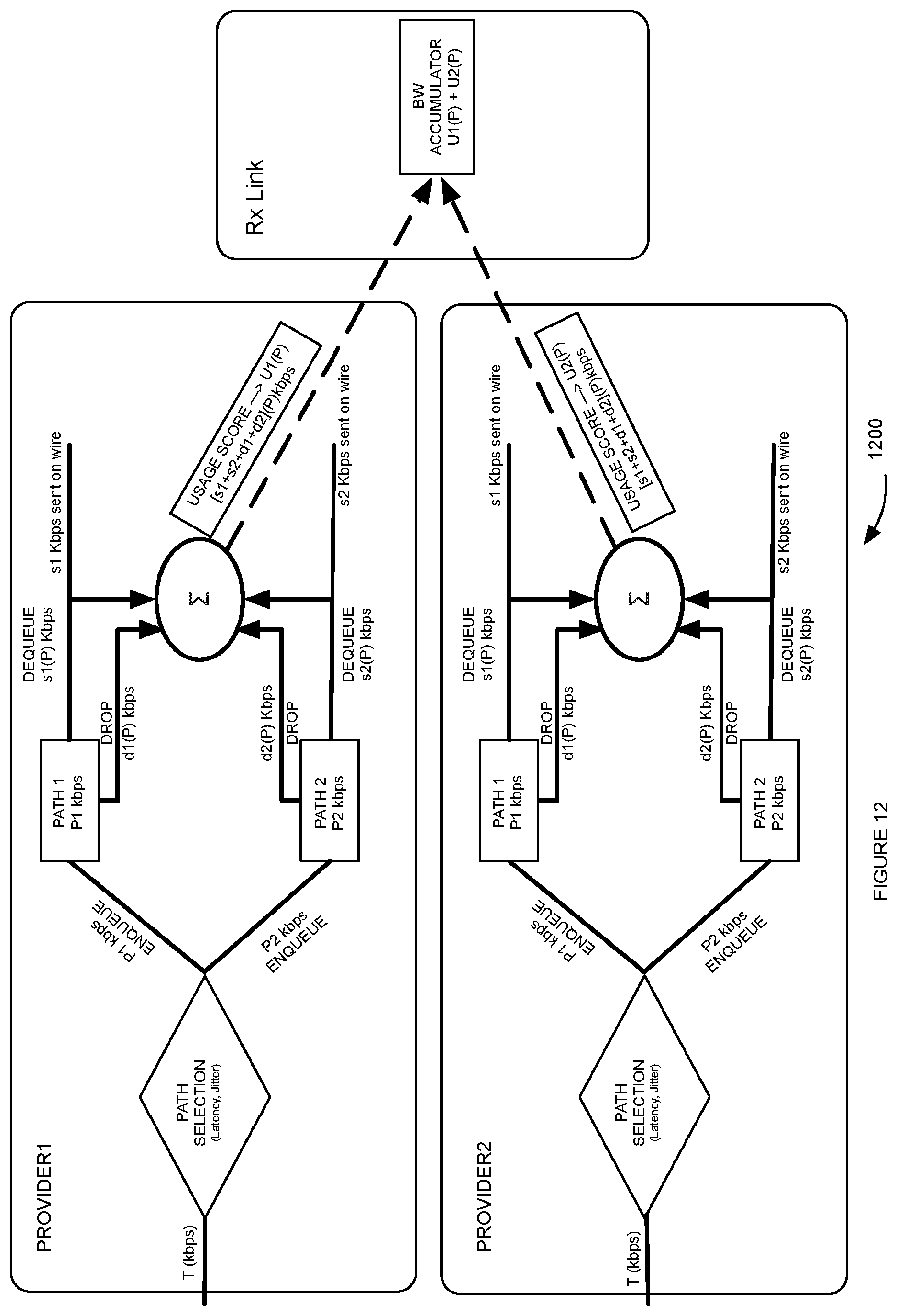
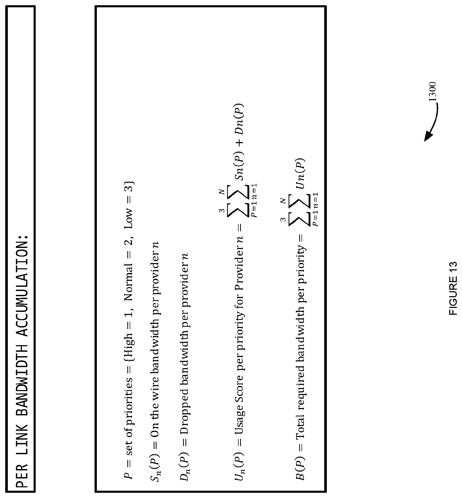
[0079] FIG. 15 illustrates an example Multi-Source Inbound QoS algorithm 1500, according to some embodiments. In step 1502, process 1500 can calculate usage computation. For example, step 1502 can calculate current usage rates of providers classified by traffic priority. FIG. 12 illustrates an example process 1200 for calculating usage, according to some embodiments. Each VELOCLOUD Endpoint in the VELOCLOUD Network can calculate a score for each of the high, normal and low priority traffic to be transmitted to the receiver. The usage score can account for traffic that is sent on the wire and also traffic that is dropped because of lack of capacity on that link. This usage score can be the total requirement for the provider to send traffic to the receiver without dropping any packets. This usage score can be communicated to the receiver which stores this in a bandwidth accumulator. The receiver can now use the sum of the scores, that were received from its peers, stored in the bandwidth accumulator, to determine the bandwidth needs of each peer on a per priority basis, and to distribute bandwidth fairly between all peers. FIG. 13 illustrates an example screenshot of an algorithm for calculating a usage score, according to some embodiments. Upon receipt of this information from all peers, the receiving edge, the bandwidth accumulator can calculate a total score for each priority which is a summation of the individual scores for a given priority.
[0080] In step 1504, process 1500 can implement fair sharing among providers (e.g. providers 802-806, etc.). For example, step 1504 can allocate bandwidth to providers based on the traffic priority and provider share ratios.
[0081] An example of allocating bandwidth to providers is now discussed. For example, the score that was communicated from a provider can be considered to be the bandwidth required for a given priority. This is because process 1500 measures the received and dropped Kbps, thus the sum of these is the amount of bandwidth that would be used to eliminate drops at the current traffic rate. The total bandwidth to be used can be considered to be the sum of all the required bandwidths per priority. If the total bandwidth to be used is less than the total link bandwidth, then it can be allocated to the provider in toto. If the total bandwidth to be used is greater than the total link bandwidth, then for each priority we assign the minimum of the bandwidth required or the total link bandwidth divided by the number of peers.
[0082] In step 1506, process 1500 can allocate excess. For example, step 1506 can adjust excess bandwidth, if any, amongst providers. For example, process 1500 can iterate through each peer and assign any leftover bandwidth to the first peer that we find which still requires more bandwidth.
[0083] In step 1508, process 1500 can implement link sharing at provider level. For example, process 1508 can share the allocated bandwidth by configuring the link scheduler at the provider when appropriate in such a way that path selection policies are honored.
CONCLUSION
[0084] Although the present embodiments have been described with reference to specific example embodiments, various modifications and changes can be made to these embodiments without departing from the broader spirit and scope of the various embodiments. For example, the various devices, modules, etc. described herein can be enabled and operated using hardware circuitry, firmware, software or any combination of hardware, firmware, and software (e.g., embodied in a machine-readable medium).
[0085] In addition, it can be appreciated that the various operations, processes, and methods disclosed herein can be embodied in a machine-readable medium and/or a machine accessible medium compatible with a data processing system (e.g., a computer system), and can be performed in any order (e.g., including using means for achieving the various operations). Accordingly, the specification and drawings are to be regarded in an illustrative rather than a restrictive sense. In some embodiments, the machine-readable medium can be a non-transitory form of machine-readable medium.
* * * * *
D00000
D00001
D00002
D00003
D00004
D00005
D00006
D00007
D00008
D00009
D00010
D00011
D00012
D00013
D00014
D00015

XML
uspto.report is an independent third-party trademark research tool that is not affiliated, endorsed, or sponsored by the United States Patent and Trademark Office (USPTO) or any other governmental organization. The information provided by uspto.report is based on publicly available data at the time of writing and is intended for informational purposes only.
While we strive to provide accurate and up-to-date information, we do not guarantee the accuracy, completeness, reliability, or suitability of the information displayed on this site. The use of this site is at your own risk. Any reliance you place on such information is therefore strictly at your own risk.
All official trademark data, including owner information, should be verified by visiting the official USPTO website at www.uspto.gov. This site is not intended to replace professional legal advice and should not be used as a substitute for consulting with a legal professional who is knowledgeable about trademark law.