Control of Multiple Energy Storages In A Microgrid
Majumder; Ritwik
U.S. patent application number 16/618666 was filed with the patent office on 2020-07-23 for control of multiple energy storages in a microgrid. The applicant listed for this patent is ABB Schweiz AG. Invention is credited to Ritwik Majumder.
| Application Number | 20200235578 16/618666 |
| Document ID | / |
| Family ID | 59014628 |
| Filed Date | 2020-07-23 |

| United States Patent Application | 20200235578 |
| Kind Code | A1 |
| Majumder; Ritwik | July 23, 2020 |
Control of Multiple Energy Storages In A Microgrid
Abstract
A method performed by a network controller of an electrical microgrid having a plurality of energy storages. Each of the energy storages is associated with a respective storage controller. The method includes receiving information about a measurement made at a remote location in the microgrid. The method also includes obtaining respective participation factors in respect of the remote location for each of at least a first energy storage and a second energy storage of the plurality of energy storages. The method also includes obtaining respective states of charge for each of the at least first and second energy storages. The method also includes, for each of the at least first and second energy storages, calculating a reference value for the energy storage, and sending the reference value to the storage controller with which the energy storage is associated. The calculating includes calculating the reference value based on the obtained participation factors and the obtained states of charge.
| Inventors: | Majumder; Ritwik; (Vasteras, SE) | ||||||||||
| Applicant: |
|
||||||||||
|---|---|---|---|---|---|---|---|---|---|---|---|
| Family ID: | 59014628 | ||||||||||
| Appl. No.: | 16/618666 | ||||||||||
| Filed: | June 1, 2017 | ||||||||||
| PCT Filed: | June 1, 2017 | ||||||||||
| PCT NO: | PCT/EP2017/063387 | ||||||||||
| 371 Date: | December 2, 2019 |
| Current U.S. Class: | 1/1 |
| Current CPC Class: | G05B 19/0423 20130101; H02J 3/388 20200101; G01R 19/2513 20130101; G05B 2219/24215 20130101; H02J 3/381 20130101; H02J 3/28 20130101; H02J 13/00002 20200101; G05B 2219/21087 20130101 |
| International Class: | H02J 3/28 20060101 H02J003/28; H02J 3/38 20060101 H02J003/38; H02J 13/00 20060101 H02J013/00; G05B 19/042 20060101 G05B019/042 |
Claims
1. A method performed by a network controller (4) of an electrical power microgrid (1) comprising a plurality of energy storages (2), each energy storage being associated with a respective storage controller (3), the method comprising: receiving (S1) information about a measurement made at a remote location (RL) in the microgrid; obtaining (S2) respective participation factors in respect of the remote location for each of at least a first energy storage (2a) and a second energy storage (2b) of the plurality of energy storages; obtaining (S3) respective states of charge of each of said at least first and second energy storages; and for each of the at least first and second energy storages (2a/2b): calculating (S4) a reference value for the energy storage, and sending (S5) the reference value to the storage controller (3a/3b) with which the energy storage is associated; wherein the calculating (S4) comprises calculating the reference value based on the obtained (S2) participation factors and the obtained (S3) states of charge.
2. The method of claim 1, wherein the calculating (S4) comprises calculating the reference value based also on received information about respective statuses of circuit breakers (7) in the microgrid (1).
3. The method of any preceding claim, wherein the measurement comprises a voltage measurement and the reference value is for a voltage reference of the energy storage (2), and/or wherein the measurement comprises a current measurement and the reference value is for a current reference of the energy storage (2).
4. The method of any preceding claim, wherein the obtaining (S2) of participation factors comprises obtaining participation factors for current control mode and/or for voltage control mode of the microgrid (1).
5. The method of any preceding claim, wherein the obtaining (S2) of participation factors comprises receiving the participation factors from the respective storage controllers (3) and/or from an operating system of the microgrid (1), e.g. a supervisory control and data acquisition, SCADA, operating system.
6. The method of any preceding claim, wherein the measurement indicates that the microgrid (1) has been islanded.
7. The method of any claim 1-5, wherein the measurement indicates a power oscillation in the microgrid (1).
8. The method of any preceding claim, wherein the remote location (RL) is at a Point of Common Coupling, PCC, (7) of the microgrid (1) with an AC grid (6).
9. The method of any claim 1-7, wherein the remote location (RL) is at a location where a distributed generator, DG, (5) is connected in the microgrid (1).
10. A computer program product comprising computer-executable components for causing a network controller (4) to perform the method of any one of claims 1-9 when the computer-executable components are run on processing circuitry comprised in the network controller.
11. A network controller (4) for an electrical microgrid (1) comprising a plurality of energy storages (2), each energy storage being associated with a respective storage controller (3), the network controller comprising: processing circuitry; and storage storing instructions executable by said processing circuitry whereby said network controller is operative to: receive information about a measurement made at a remote location (RL) in the microgrid; obtain respective participation factors in respect of the remote location for each of at least a first energy storage (2a) and a second energy storage (2b) of the plurality of energy storages; obtain respective states of charge of each of said at least first and second energy storages; and for each of the at least first and second energy storages (2a/2b): calculate a reference value for the energy storage, and send the reference value to the storage controller (3a/3b) with which the energy storage is associated; wherein the calculating comprises calculating the reference value based on the obtained participation factors and the obtained states of charge.
12. A method performed by a storage controller (3) associated with an energy storage (2) in an electrical microgrid (1), the method comprising: controlling (S11) the energy storage based on a pre-set reference value; from a network controller (4) of the microgrid, receiving (S12) an updated reference value; receiving (S13) information about a measurement made at a local location (LL); adjusting (S14) the pre-set reference value based on both the received (S12) updated reference value and the received (S13) measurement information; and controlling (S15) the energy storage based on the adjusted (S14) reference value.
13. The method of claim 12, wherein the local location is at a location where the energy storage (2) is connected in the microgrid (1).
14. A computer program product comprising computer-executable components for causing a storage controller (3) to perform the method of any one of claims 12-13 when the computer-executable components are run on processing circuitry comprised in the storage controller.
15. A storage controller (3) configured for being associated with an energy storage (2) in an electrical microgrid (1), the storage controller comprising: processing circuitry; and storage storing instructions executable by said processing circuitry whereby said storage controller is operative to: control the energy storage (2) based on a pre-set reference value; from a network controller (4) of the microgrid, receive an updated reference value; receive information about a measurement made at a local location (LL); adjust the pre-set reference value based on both the received updated reference value and the received measurement information; and control the energy storage based on the adjusted reference value.
16. An electrical microgrid (1) comprising a network controller (4) of claim 11 and a plurality of storage controllers (3) of claim 15.
Description
TECHNICAL FIELD
[0001] The present disclosure relates to a methods and devices for controlling a plurality of energy storages in a microgrid.
BACKGROUND
[0002] A microgrid is a localized grouping of distributed generators (DG), energy storage, and loads that normally operates connected to a traditional centralized grid (macrogrid) via a point of common coupling (PCC). This single point of common coupling with the macrogrid can be disconnected, islanding the microgrid. Microgrids are part of a structure aiming at producing electrical power locally from many small energy sources, DGs. In a microgrid, a DG is often connected via a converter which controls the output of the DG, i.e. the power injected into the microgrid.
[0003] Energy storages can provide energy or power within a microgrid depending on the need. A microgrid requires a high energy storage for supplying power balance for longer time, and stability is improved with a high power storage. In a microgrid, system stability is improved with application of an energy storage for continuous real and reactive power injection which also acts as a stabilizer for the microgrid. The main control philosophy for such stabilizing action is real and reactive power injection based on local frequency and voltage deviation, respectively.
[0004] In most scenarios, a larger storage/stabilizer is economical. However, in a microgrid, depending on growth, expansion and with higher penetration of DGs, it may be required to add a new storage/stabilizer in an existing microgrid, which leads to multiple storage scenarios. Moreover, a planned multiple stabilizer scenario can also be beneficial for a microgrid with critical loads and frequency dependencies.
[0005] In a microgrid having a plurality of energy storages, it is necessary to decide which storage should be used to act in view of an obtained measurement, e.g. voltage or frequency measurement.
[0006] U.S. Pat. No. 8,946,929 discloses a microgrid comprising a plurality of energy storages, each connected to either of a direct current (DC) bus and an alternating current (AC) bus. Each energy storage has a local controller which keeps track of the State of Charge (SoC) and health of its storage and which is connected with a master microgrid controller via an energy storage system bus. The document is concerned with properly determining SoC to avoid overcharging or overdischarging the storage, thereby preserving its health and prolonging its lifespan. A master microgrid controller may perform charge/discharge operation for the subordinate energy storage components based upon the microgrid power status and the SoC and state of health status of the energy storage components.
SUMMARY
[0007] An objective of the present invention is to provide a method for dynamic participation of energy storages in a microgrid during power imbalances in a microgrid.
[0008] According to an aspect of the present invention, there is provided a method performed by a network controller of an electrical microgrid comprising a plurality of energy storages. Each of the energy storages is associated with a respective storage controller. The method comprises receiving information about a measurement made at a remote location (RL) in the microgrid. The method also comprises obtaining respective participation factors in respect of the remote location for each of at least a first energy storage and a second energy storage of the plurality of energy storages. The method also comprises obtaining respective states of charge of each of said at least first and second energy storages. The method also comprises, for each of the at least first and second energy storages, calculating a reference value for the energy storage, and sending the reference value to the storage controller with which the energy storage is associated. The calculating comprises calculating the reference value based on the obtained participation factors and the obtained states of charge.
[0009] According to another aspect of the present invention, there is provided a computer program product comprising computer-executable components for causing a network controller to perform an embodiment of a method of the present disclosure when the computer-executable components are run on processing circuitry comprised in the storage controller.
[0010] According to another aspect of the present invention, there is provided a network controller for an electrical microgrid comprising a plurality of energy storages. Each of the energy storages is associated with a respective storage controller. The network controller comprises processing circuitry, and storage storing instructions executable by said processing circuitry whereby said network controller is operative to receive information about a measurement made at a remote location in the microgrid. The network controller is also operative to obtain respective participation factors in respect of the remote location for each of at least a first energy storage and a second energy storage of the plurality of energy storages. The network controller is also operative to obtain respective states of charge of each of said at least first and second energy storages. The network controller is also operative to, for each of the at least first and second energy storages, calculate a reference value for the energy storage, and send the reference value to the storage controller with which the energy storage is associated. The calculating comprises calculating the reference value based on the obtained participation factors and the obtained states of charge.
[0011] According to another aspect of the present invention, there is provided a method performed by a storage controller associated with an energy storage in an electrical microgrid. The method comprises controlling the energy storage based on a preset reference value. The method also comprises, from a network controller of the microgrid, receiving an updated reference value. The method also comprises receiving information about a measurement made at a local location (LL). The method also comprises adjusting the preset reference value based on both the received updated reference value and the received measurement information. The method also comprises controlling the energy storage based on the adjusted reference value.
[0012] According to another aspect of the present invention, there is provided a computer program product comprising computer-executable components for causing a storage controller to perform an embodiment of a method of the present disclosure when the computer-executable components are run on processing circuitry comprised in the storage controller.
[0013] According to another aspect of the present invention, there is provided a storage controller configured for being associated with an energy storage in an electrical microgrid. The storage controller comprises processing circuitry, and storage storing instructions executable by said processing circuitry whereby said storage controller is operative to control the energy storage based on a preset reference value. The storage controller is also operative to, from a network controller of the microgrid, receive an updated reference value. The storage controller is also operative to receive information about a measurement made at a local location. The storage controller is also operative to adjust the preset reference value based on both the received updated reference value and the received measurement information. The storage controller is also operative to control the energy storage based on the adjusted reference value.
[0014] According to another aspect of the present invention, there is provided an electrical power microgrid comprising an embodiment of a network controller of the present disclosure and a plurality of storage controllers in accordance with an embodiment of the present disclosure.
[0015] By means of respective participation factors, a plurality of energy storages in the microgrid can be controlled by the central network controller, via local storage controllers, to react to a measurement obtained from a remote location (i.e. a location which is not local to an energy storage) in the microgrid. A participation factor may e.g. be regarded as the impact of active power injection from a first energy storage on the frequency deviation measured at the remote location or influence of reactive power injection from a second energy storage on the voltage measured at the remote location. The participation factors may alternatively/additionally be related to the influence on the dominant mode (lower frequency system oscillations) from the first energy storage active power injections or second energy storage reactive power injection for example.
[0016] The SoC of the respective energy storages is obtained to ensure that the energy storages hold enough energy/power to perform the action implied by the participation factors. If the SoC of an energy storage is too high or too low for the action of that energy storage implied by the participation factors, the calculating of the reference values are adjusted accordingly. Otherwise, if the SoC is not an issue for performing the actions implied by the participation factors, this is noted and the reference values are not adjusted in view of the SoC when they are calculated.
[0017] It is to be noted that any feature of any of the aspects may be applied to any other aspect, wherever appropriate. Likewise, any advantage of any of the aspects may apply to any of the other aspects. Other objectives, features and advantages of the enclosed embodiments will be apparent from the following detailed disclosure, from the attached dependent claims as well as from the drawings.
[0018] Generally, all terms used in the claims are to be interpreted according to their ordinary meaning in the technical field, unless explicitly defined otherwise herein. All references to "a/an/the element, apparatus, component, means, step, etc.", are to be interpreted openly as referring to at least one instance of the element, apparatus, component, means, step, etc., unless explicitly stated otherwise. The steps of any method disclosed herein do not have to be performed in the exact order disclosed, unless explicitly stated. The use of "first", "second" etc., for different features/components of the present disclosure are only intended to distinguish the features/components from other similar features/components and not to impart any order or hierarchy to the features/components.
BRIEF DESCRIPTION OF THE DRAWINGS
[0019] Embodiments will be described, by way of example, with reference to the accompanying drawings, in which:
[0020] FIG. 1a is a schematic circuit diagram of an embodiment of a microgrid, with storage control based on a remote measurement, in accordance with the present invention.
[0021] FIG. 1b is a schematic block diagram of an embodiment of a control arrangement for the microgrid of FIG. 1a.
[0022] FIG. 2 is a schematic circuit diagram of an embodiment of a microgrid, with storage control based on a local measurement, in accordance with the present invention.
[0023] FIG. 3 is a schematic circuit diagram of an embodiment of a microgrid, with storage control based on a measurement at the PCC, in accordance with the present invention.
[0024] FIG. 4 is a schematic circuit diagram of an embodiment of a microgrid connected to another microgrid, with storage control based on remote measurements, in accordance with the present invention.
[0025] FIG. 5 is a schematic graph illustrating how a (e.g. voltage or current) deviation measured at a remote location in FIG. 4 can be counteracted by controlling two different energy storages to perform different actions.
[0026] FIG. 6 is a schematic flow chart of an embodiment of a method performed by the network controller, in accordance with the present invention.
[0027] FIG. 7 is a schematic flow chart of an embodiment of a method performed by a storage controller, in accordance with the present invention.
DETAILED DESCRIPTION
[0028] Embodiments will now be described more fully hereinafter with reference to the accompanying drawings, in which certain embodiments are shown. However, other embodiments in many different forms are possible within the scope of the present disclosure. Rather, the following embodiments are provided by way of example so that this disclosure will be thorough and complete, and will fully convey the scope of the disclosure to those skilled in the art. Like numbers refer to like elements throughout the description.
[0029] The ability of an energy storage to participate in system dynamics in a microgrid depends on its controllability, and is in prior art usually determined based on available energy (SoC) of the energy storage. Measurement based injections of power from the energy storage into the microgrid are usually activated based on a detected deviation of a system parameters (e.g. frequency, voltage, current etc.). In accordance with the present disclosure, a common signal or measurement deviation is used to decide individual storage actions [e.g. power injection profiles, grid forming, VSM (Virtual Synchronous Machine) operation] for each energy storage. The actions are generated based on calculated participation factors of the storages for the measured location and (optionally) status of the breakers connecting the energy storages in the microgrid and/or connecting the microgrid at a PCC. The SoC of the respective energy storages are monitored in order to ensure that the available stored energy is adequate for performing the action (injection or absorption of electrical energy) implied by the participation factors.
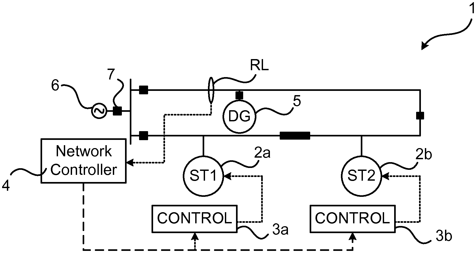
[0030] FIG. 1a illustrates an embodiment of a microgrid 1 comprising a plurality of energy storages 2, here a first energy storage 2a and a second energy storage 2b. Each energy storage 2 is associated with (controlled by) a local storage controller 3, i.e. a first storage controller 3a for the first energy storage 2a and a second storage controller 3b for the second energy storage 2b. The microgrid also typically comprises at least one DG 5, optionally any number of loads (not shown), and circuit breakers, including a circuit breaker 7 at the PCC with another power grid 6, e.g. an AC grid such as a power distribution grid, or another microgrid.
[0031] A central network controller 4 is arranged for controlling the microgrid 1, e.g. by sending reference values to the storage controllers for updating their respective references (e.g. voltage, frequency, current and/or power references). As indicated by the dotted line in the figure, the network controller 4 obtains information about a measurement (e.g. voltage, frequency, current and/or power measurement) made at a remote location RL in the microgrid 1. That the RL is remote indicates that the location is not local to one of the energy storages 2, e.g. at the point where the energy storage is connected in the microgrid. Examples of remote locations include, but are not limited to, a location at a point where a DG 5 or load is connected in the microgrid, or a location at a PCC or breaker 7 in the microgrid. As indicated by the dashed lines in the figure, the network controller 4 may then send control signals to the respective storage controllers 3, comprising reference values, for centrally controlling the energy storages 2 based on the measurement at the RL. The reference values of the control signals may in other embodiments be based on any number of measurements at any number of remote locations.
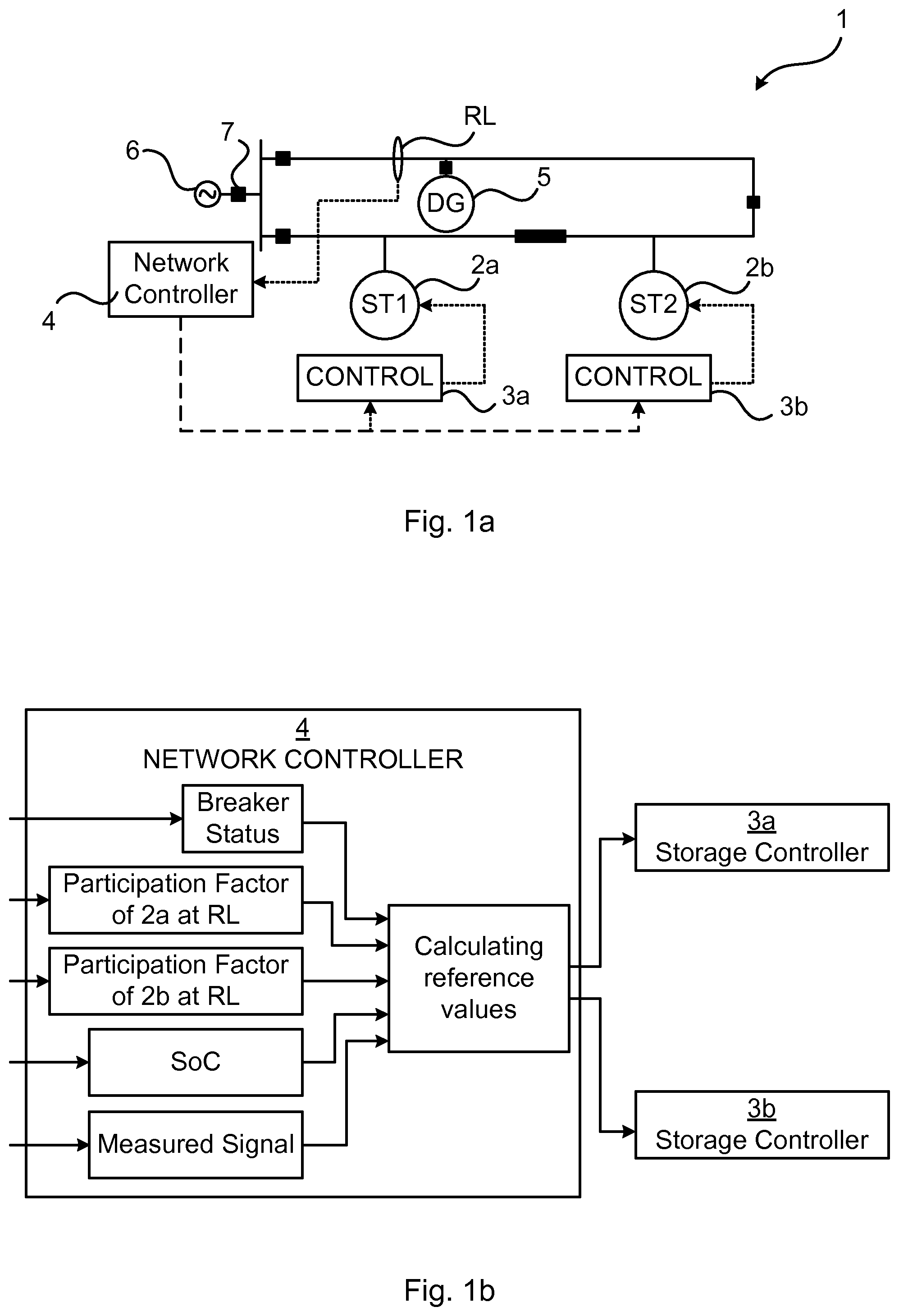
[0032] FIG. 1b illustrates examples of input and output signals of a network controller 4 in a control arrangement which also comprises the storage controllers 3, here first and second storage controllers 3a and 3b, of a microgrid, e.g. the microgrid illustrated in FIG. 1a. The input comprises information about the measurement at the remote locations, and may also comprise any of:
[0033] SoC of the first and second energy storages 2a and 2b, e.g. received from the first and second storage controllers 3a and 3b which may monitor the SoC of their respective associated energy storage 2a and 2b. The SoC of the respective energy storages are monitored in order to ensure that the available stored energy is adequate for performing the action (injection or absorption of electrical energy) implied by the participation factors.
[0034] The respective participation factors, e.g. dynamically calculated, of the first and second storages 2a and 2b in respect of the RL. Based on the network connection, microgrid assets (e.g. loads and DGs 5) and network controller parameters, the participation factor regarding each RL is calculated for each measured parameter (e.g. voltage, frequency, current and/or power, corresponding to control modes such as voltage, frequency, current and/or power control mode) against change in storage references (or states e.g. output current, voltage etc.). These may be calculated at the microgrid operating system and communicated to the network controller 4. Alternatively, in some embodiments of the present invention, the participation factors are calculated, or otherwise determined, in by the network controller. As another alternative, each storage controller 3 may calculate the participation factor of its associated energy storage, e.g. in terms of peak power injection, oscillation frequency, energy etc. Each storage controller 3 can calculate participation factors for each RL used.
[0035] Status of breakers in the microgrid, e.g. the breaker 7 at the PCC which may indicate whether the microgrid is islanded or not. Also the status (e.g. open or closed) of other breakers in the microgrid may be relevant to the ability of each storage 2 to affect the measured property at the RL. The breaker status information can be fed to the network controller 4 directly from the relay or through the microgrid operating system e.g. a supervisory control and data acquisition (SCADA) operating system.
[0036] By means of data storage and processing circuitry of the network controller 4, the network controller may then use the inputted information to calculate respective reference values for each of the first and second energy storages 2a and 2b. Control signals comprising the respective reference values are outputted (sent) to each respective first and second storage controller 3a and 3b.
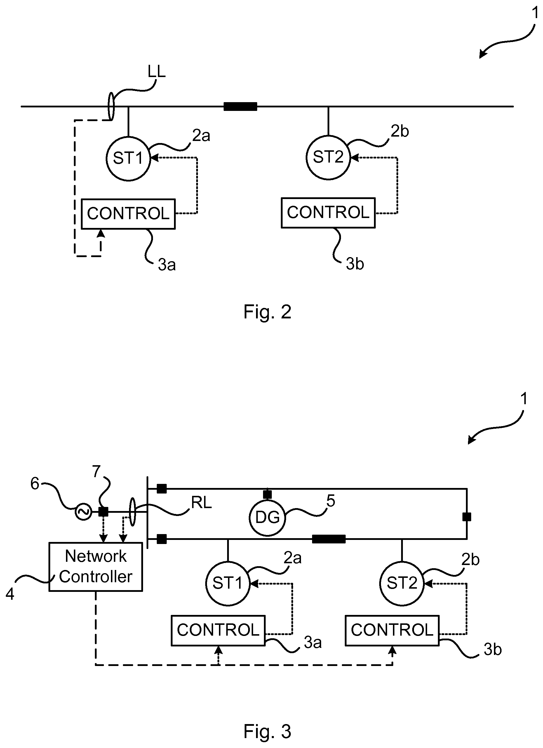
[0037] FIG. 2 illustrates an embodiment of a part of a microgrid 1 in which information about a local measurement at a local location LL at the first storage 2a is obtained by the first storage controller 3a, directly i.e. not via the network controller 4. That a storage controller 3 controls its associated energy storage 2 based on control signals from the network controller 4 relating to a measurement at a remote location RL does not preclude that the storage controller 3 may also control the energy storage 2 based on locally obtained measurement(s) from a local location LL, e.g. at a point where the energy storage 2 is connected in the microgrid 1. The storage controller 3 may thus adjust its reference based on both the local measurement and on the remote measurement (by means of the control signal from the network controller 4). A local signal deviation as measured at a LL may have higher priority than a signal deviation at a RL. Such a deviation may be corrected based on the local measurements. This avoids delays in corrective actions for larger disturbance near the storage device.
EXAMPLE 1
Selection of Real and Reactive Power Injections
[0038] With reference to FIG. 1a, a decreasing power output of the DG 5, e.g. while the microgrid 1 is islanded, is detected with a slow fall of voltage and frequency as measured at the RL. Before this decreasing power output results in tripping and load shedding relays or other protective equipment, energy storages 2a and 2b are employed to restore voltage and frequency of the microgrid. According to an embodiment of the present invention, the network controller 4 calculates reference values for participation of the first and second energy storages 2a and 2b and decides on e.g. changes in real power injection from the first energy storage 2a while the reactive power support is provided by the second energy storage 2b.
EXAMPLE 2
Selection of Grid Forming Energy Storages
[0039] With reference to FIG. 3, following a fault and/or during islanding, detected at the PCC breaker 7, the network controller 4 calculates reference values for the first and second energy storages 2a and 2b, resulting in that the second energy storage 2b, as controlled by the second storage controller 3b, changes mode to grid forming mode while the first energy storage 2a, as controlled by the first storage controller 3a, remains in its present mode e.g. voltage control mode. This could be decided due to location of the loads and SoC of the respective storages 2a and 2b. For large and foreseeable disturbances, as when the microgrid is islanded, the reference values may be precalculated for immediate implementations.
EXAMPLE 3
Selection of Energy Storages for Damping Control
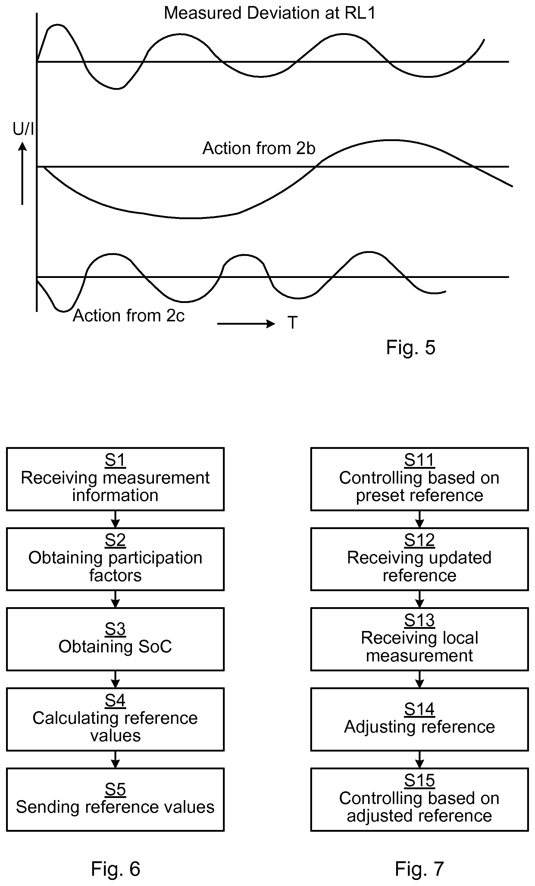
[0040] With reference to FIG. 4, in which the power grid 6 with which the microgrid 1 is connected at the PCC 7 is another microgrid, the network controller 4 which controls both microgrids 1 and 6 calculates reference values for energy storages 2 of both microgrids 1 and 6, resulting in the selection of the second energy storage 2b of microgrid 1 and the third energy storage 2c of the power grid 6 for an inter area mode oscillation damping measured at the two remote locations RL1 and RL2 on either side of the PCC 7. The action performed by the second and third energy storages 2a and 2c could for instance be change in power injection at different frequencies, as illustrated in FIG. 5.
[0041] With reference to FIGS. 6 and 7, method embodiments of the present invention, performed in/by the network controller 4 or any or each of the storage controllers 3 are presented below.
[0042] FIG. 6 is a flow chart illustrating a method performed by a network controller 4 of the electrical power microgrid 1 comprising a plurality of energy storages 2. Each energy storage is associated with (controlled by) a respective storage controller 3. The method comprises receiving S1 information about a measurement made at a remote location RL in the microgrid. The method also comprises obtaining S2 respective participation factors in respect of the remote location for each of at least a first energy storage 2a and a second energy storage 2b of the plurality of energy storages. The method also comprises obtaining S3 respective states of charge of each of said at least first and second energy storages, to ensure the calculated S4 reference values based on system disturbance and participation factor of the storage can be archived (otherwise they are adjusted accordingly). The method also comprises, for each of the at least first and second energy storages 2a or 2b, calculating S4 a reference value for the energy storage and sending S5 the reference value to the storage controller 3a or 3b with which the energy storage is associated. The calculating S4 comprises calculating the reference value based on the obtained S2 participation factors and the obtained S3 states of charge.
[0043] FIG. 7 is a flow chart illustrating a method performed by a storage controller 3 associated with an energy storage 2 in the electrical microgrid 1. The method comprises controlling S11 the energy storage based on a preset reference value. The method also comprises, from a network controller 4 of the microgrid, receiving S12 an updated reference value. The method also comprises receiving S13 information about a measurement made at a local location LL. The method also comprises adjusting S14 the preset reference value based on both the received S12 updated reference value and the received S13 measurement information. The method also comprises controlling S15 the energy storage based on the adjusted S14 reference value.
[0044] The present disclosure has mainly been described above with reference to a few embodiments. However, as is readily appreciated by a person skilled in the art, other embodiments than the ones disclosed above are equally possible within the scope of the present disclosure, as defined by the appended claims.
* * * * *
D00000
D00001
D00002
D00003
D00004
XML
uspto.report is an independent third-party trademark research tool that is not affiliated, endorsed, or sponsored by the United States Patent and Trademark Office (USPTO) or any other governmental organization. The information provided by uspto.report is based on publicly available data at the time of writing and is intended for informational purposes only.
While we strive to provide accurate and up-to-date information, we do not guarantee the accuracy, completeness, reliability, or suitability of the information displayed on this site. The use of this site is at your own risk. Any reliance you place on such information is therefore strictly at your own risk.
All official trademark data, including owner information, should be verified by visiting the official USPTO website at www.uspto.gov. This site is not intended to replace professional legal advice and should not be used as a substitute for consulting with a legal professional who is knowledgeable about trademark law.