Substrate Processing Device
Jeong; WonKi
U.S. patent application number 16/704835 was filed with the patent office on 2020-07-23 for substrate processing device. The applicant listed for this patent is ASM IP Holding B.V.. Invention is credited to WonKi Jeong.
| Application Number | 20200234989 16/704835 |
| Document ID | / |
| Family ID | 71610119 |
| Filed Date | 2020-07-23 |


View All Diagrams
| United States Patent Application | 20200234989 |
| Kind Code | A1 |
| Jeong; WonKi | July 23, 2020 |
SUBSTRATE PROCESSING DEVICE
Abstract
Provided is an exhaust device with improved exhaust efficiency. The exhaust device includes: a plurality of exhaust ports in communication with an exhaust space and configured to exhaust gas in a first direction; a plurality of exhaust paths respectively connected to the plurality of exhaust ports; and a transfer port in communication with the plurality of exhaust paths and configured to exhaust gas in a second direction. More uniform processing of a substrate may be achieved through a substrate processing device using such an exhaust device.
| Inventors: | Jeong; WonKi; (Cheonan-si, KR) | ||||||||||
| Applicant: |
|
||||||||||
|---|---|---|---|---|---|---|---|---|---|---|---|
| Family ID: | 71610119 | ||||||||||
| Appl. No.: | 16/704835 | ||||||||||
| Filed: | December 5, 2019 |
| Current U.S. Class: | 1/1 |
| Current CPC Class: | H01L 21/67393 20130101 |
| International Class: | H01L 21/673 20060101 H01L021/673 |
Foreign Application Data
| Date | Code | Application Number |
|---|---|---|
| Jan 22, 2019 | KR | 10-2019-0008341 |
Claims
1. A substrate processing device comprising: a first reactor comprising a first reaction space for processing a first substrate and a first exhaust space for exhausting gas in the first reaction space; a first exhaust path extending to surround at least a portion of the first exhaust space; a second exhaust path extending to surround at least a portion of the first exhaust space; a first exhaust port connecting one end of the first exhaust path and the first exhaust space; a second exhaust port connecting one end of the second exhaust path and the first exhaust space; and a first transfer port connecting the first exhaust path and the second exhaust path.
2. The substrate processing device of claim 1, wherein a portion of the gas in the first reaction space is exhausted through the first exhaust port, the first exhaust path, and the first transfer port, and another portion of the gas in the first reaction space is exhausted through the second exhaust port, the second exhaust path, and the first transfer port.
3. The substrate processing device of claim 1, wherein the gas in the first exhaust space is exhausted upward through the first exhaust port to the first exhaust path, and the gas in the first exhaust space is exhausted upward through the second exhaust port to the second exhaust path.
4. The substrate processing device of claim 3, further comprising: a first transfer path connected to the first transfer port, wherein the gas in the first exhaust path and the second exhaust path is exhausted downward to the first transfer path through the first transfer port.
5. The substrate processing device of claim 4, further comprising: a partition wall accommodating the first reactor, wherein the first transfer path is arranged in the partition wall.
6. The substrate processing device of claim 1, further comprising: a second reactor comprising a second reaction space for processing a second substrate and a second exhaust space for exhausting gas in the second reaction space; a third exhaust path extending to surround at least a portion of the second exhaust space; a fourth exhaust path extending to surround at least a portion of the second exhaust space; a third exhaust port connecting one end of the third exhaust path and the second exhaust space; a fourth exhaust port connecting one end of the fourth exhaust path and the second exhaust space; and a second transfer port connecting the third exhaust path and the fourth exhaust path.
7. The substrate processing device of claim 6, further comprising: a partition wall accommodating the first reactor and the second reactor, wherein a plurality of substrates are simultaneously processed through the first reactor and the second reactor.
8. The substrate processing device of claim 7, further comprising: a first transfer path connected to the first transfer port; a second transfer path connected to the second transfer port; a connection port connecting the first transfer path and the second transfer path; and an exhaust pump connected to the connection port, wherein the first transfer path and the second transfer path are arranged in the partition wall, and the connection port and the exhaust pump are located outside the partition wall and arranged asymmetrically with respect to the substrate processing device.
9. The substrate processing device of claim 7, wherein each of the first transfer port and the second transfer port is adjacent to a corner portion of the partition wall.
10. The substrate processing device of claim 1, wherein the first reactor comprises: a substrate supporting unit; a first lid comprising a processing unit and arranged on the substrate supporting unit; and a second lid having a first exhaust space formed therein and arranged between the substrate supporting unit and the first lid.
11. The substrate processing device of claim 10, wherein the first exhaust space extends to surround the first reaction space, and a channel is formed between the first exhaust space and the first reaction space such that the first exhaust space is in communication with the first reaction space through the channel.
12. A substrate processing device comprising: a partition wall having a plurality of substrate supporting units arranged therein; a lid arranged on the partition wall and providing an exhaust space; a plurality of exhaust ports in communication with the exhaust space and configured to exhaust gas in a first direction; a plurality of exhaust paths respectively connected to the plurality of exhaust ports; and a transfer port in communication with the plurality of exhaust paths and configured to exhaust gas in a second direction.
13. The substrate processing device of claim 12, wherein the plurality of exhaust paths comprise: a first exhaust path extending to surround at least a portion of the exhaust space; and a second exhaust path extending to surround at least a portion of the exhaust space, wherein the plurality of exhaust ports comprise: a first exhaust port connecting one end of the first exhaust path and the exhaust space; and a second exhaust port connecting one end of the second exhaust path and the exhaust space.
14. The substrate processing device of claim 12, wherein a plurality of processing units are formed inside the lid.
15. The substrate processing device of claim 12, wherein a plurality of reaction spaces are defined by the plurality of substrate supporting units and the plurality of processing units.
16. The substrate processing device of claim 12, further comprising: a top lid arranged between the partition wall and the lid; and a flow control ring arranged on the top lid between the top lid and each of the plurality of substrate supporting units and spaced apart from each of the plurality of substrate supporting units to form a gap, wherein the flow control ring is slidably arranged on the top lid.
17. The substrate processing device of claim 12, wherein the plurality of exhaust ports are spaced apart from each other at intervals of 360/n degrees, and n is the number of the plurality of exhaust ports and a natural number of 2 or more.
18. The substrate processing device of claim 12, further comprising: a plurality of control valves respectively connected to the plurality of exhaust ports, wherein the plurality of control valves are configured to control the flow rate of gas passing through the respective exhaust ports.
19. The substrate processing device of claim 18, wherein the plurality of control valves control the flow rate of gas passing through an exhaust port located at a first distance from the transfer port to be less than the flow rate of gas passing through an exhaust port located at a second distance from the transfer port, the second distance being greater than the first distance.
20. A substrate processing device comprising: a plurality of reactors, wherein each of the plurality of reactors comprises a reaction space for processing a substrate and an exhaust space for exhausting gas in the reaction space; a partition wall accommodating the plurality of reactors; a first lid comprising a plurality of gas supply units and arranged on the partition wall; a second lid having the exhaust space formed therein and arranged between the partition wall and the first lid; a first exhaust path extending to surround at least a portion of the exhaust space; a second exhaust path extending to surround at least a portion of the exhaust space; a first exhaust port connecting one end of the first exhaust path and the exhaust space and configured to exhaust gas in the exhaust space upward; a second exhaust port connecting one end of the second exhaust path and the exhaust space and configured to exhaust gas in the exhaust space upward; and a first transfer port connecting the first exhaust path and the second exhaust path and configured to exhaust gas in the first exhaust path and the second exhaust path downward.
Description
CROSS-REFERENCE TO RELATED APPLICATION
[0001] This application claims the benefit of Korean Patent Application No. 10-2019-0008341, filed on Jan. 22, 2019, in the Korean Intellectual Property Office, the disclosure of which is incorporated herein in its entirety by reference.
BACKGROUND
1. Field
[0002] One or more embodiments relate to a substrate processing device, and more particularly, to a substrate processing device having an improved exhaust structure of a batch type reactor.
2. Description of the Related Art
[0003] In semiconductor or display processing equipment, productivity, for example, the number of substrates that can be processed per unit time, is a very important factor in mass production processes. As a device capable of mass production, there is a batch type reactor. A batch type reactor is a system in which several tens of substrates are stacked vertically, loaded into the reactor, and then processed. A batch type reactor has high productivity in that it processes dozens of substrates at a time, but the batch type reactor has a disadvantage in that it is difficult to precisely control individual substrates because one reactor processes several substrates at the same time.
[0004] For example, in a multi-reactor system equipped with multiple reactors in one chamber, a gas supply and exhaust structure for simultaneous processing of multiple substrates needs to be implemented. However, such a gas supply and exhaust structure is complicated in comparison with a gas supply and exhaust structure of a reactor system equipped with a single reactor.
[0005] In recent years, there has been increasing demand for multiple reactors capable of precise control of productivity and individual substrates. Further, as a system equipped with multiple reactors in one chamber, there is a need for a substrate processing device capable of simultaneously processing multiple substrates at the same time with precise control of individual substrates, thereby improving productivity.
SUMMARY
[0006] In the case of a multi-reactor system, each reactor has a gas supply and exhaust system, and arrangement of the exhaust system affects process reproducibility of each reactor. Accordingly, one of the problems to be solved by the present disclosure is to provide an exhaust system that improves process reproducibility between reactors.
[0007] Additional aspects will be set forth in part in the description which follows and, in part, will be apparent from the description, or may be learned by practice of the presented embodiments.
[0008] According to one or more embodiments, a substrate processing device includes: a first reactor including a first reaction space for processing a first substrate and a first exhaust space for exhausting gas in the first reaction space; a first exhaust path extending to surround at least a portion of the first exhaust space; a second exhaust path extending to surround at least a portion of the first exhaust space; a first exhaust port connecting one end of the first exhaust path to the first exhaust space; a second exhaust port connecting one end of the second exhaust path to the first exhaust space; and a first transfer port connecting the first exhaust path to the second exhaust path.
[0009] A portion of the gas in the first reaction space may be exhausted through the first exhaust port, the first exhaust path, and the first transfer port, and another portion of the gas in the first reaction space may be exhausted through the second exhaust port, the second exhaust path, and the first transfer port.
[0010] The gas in the exhaust space may be exhausted upward through the first exhaust port to the first exhaust path, and the gas in the first exhaust space may be exhausted upward through the second exhaust port to the second exhaust path.
[0011] The substrate processing device may further include: a first transfer path connected to the first transfer port, wherein the gas in the first exhaust path and the second exhaust path may be exhausted downward to the first transfer path through the first transfer port.
[0012] The substrate processing device may further include: a partition wall accommodating the first reactor, wherein the first transfer path may be arranged in the partition wall.
[0013] The substrate processing device may further include: a second reactor including a second reaction space for processing a second substrate and a second exhaust space for exhausting gas in the second reaction space; a third exhaust path extending to surround at least a portion of the second exhaust space; a fourth exhaust path extending to surround at least a portion of the second exhaust space; a third exhaust port connecting one end of the third exhaust path to the second exhaust space; a fourth exhaust port connecting one end of the fourth exhaust path to the second exhaust space; and a second transfer port connecting the third exhaust path to the fourth exhaust path.
[0014] The substrate processing device may further include: a partition wall accommodating the first reactor and the second reactor, wherein a plurality of substrates may be simultaneously processed through the first reactor and the second reactor.
[0015] The substrate processing device may further include: a first transfer path connected to the first transfer port; a second transfer path connected to the second transfer port; a connection port connecting the first transfer path to the second transfer path; and an exhaust pump connected to the connection port, wherein the first transfer path and the second transfer path may be arranged in the partition wall, and the connection port and the exhaust pump may be located outside the partition wall and arranged asymmetrically with respect to the substrate processing device.
[0016] Each of the first transfer port and the second transfer port may be adjacent to a corner portion of the partition wall.
[0017] The first reactor may include: a substrate supporting unit; a first lid including a processing unit and arranged on the substrate supporting unit; and a second lid having a first exhaust space formed therein and arranged between the substrate supporting unit and the first lid.
[0018] The first exhaust space may extend to surround the first reaction space, and a channel may be formed between the first exhaust space and the first reaction space such that the first exhaust space is in communication with the first reaction space through the channel.
[0019] According to one or more embodiments, a substrate processing device includes: a partition wall having a plurality of substrate supporting units arranged therein; a lid arranged on the partition wall and providing an exhaust space; a plurality of exhaust ports in communication with the exhaust space and configured to exhaust gas in a first direction; a plurality of exhaust paths respectively connected to the plurality of exhaust ports; and a transfer port in communication with the plurality of exhaust paths and configured to exhaust gas in a second direction.
[0020] The plurality of exhaust paths may include: a first exhaust path extending to surround at least a portion of the exhaust space; and a second exhaust path extending to surround at least a portion of the exhaust space, wherein the plurality of exhaust ports may include: a first exhaust port connecting one end of the first exhaust path to the exhaust space; and a second exhaust port connecting one end of the second exhaust path to the exhaust space.
[0021] A plurality of processing units may be formed inside the lid.
[0022] A plurality of reaction spaces may be defined by the plurality of substrate supporting units and the plurality of processing units.
[0023] The substrate processing device may further include: a top lid arranged between the partition wall and the lid; and a flow control ring arranged on the top lid between the top lid and each of the plurality of substrate supporting units and spaced apart from each of the plurality of substrate supporting units to form a gap, wherein the flow control ring may be slidably arranged on the top lid.
[0024] The plurality of exhaust ports may be spaced apart from each other at intervals of 360/n degrees, and n may be the number of the plurality of exhaust ports and a natural number of 2 or more.
[0025] The substrate processing device may further include: a plurality of control valves respectively connected to the plurality of exhaust ports, wherein the plurality of control valves may control the flow rate of gas passing through the respective exhaust ports.
[0026] The plurality of control valves may be controlled such that the flow rate of gas passing through an exhaust port located at a first distance from the transfer port is less than the flow rate of gas passing through an exhaust port located at a second distance greater than the first distance.
[0027] According to one or more embodiments, a substrate processing device includes: a plurality of reactors, wherein each of the plurality of reactors includes a reaction space for processing a substrate and an exhaust space for exhausting gas in the reaction space; a partition wall accommodating the plurality of reactors; a first lid including a plurality of gas supply units and arranged on the partition wall; a second lid having a first exhaust space formed therein and arranged between the partition wall and the first lid; a first exhaust path extending to surround at least a portion of the exhaust space; a second exhaust path extending to surround at least a portion of the exhaust space; a first exhaust port connecting one end of the first exhaust path to the exhaust space and configured to exhaust gas in the exhaust space upward; a second exhaust port connecting one end of the second exhaust path to the exhaust space and configured to exhaust gas in the exhaust space upward; and a first transfer port connecting the first exhaust path to the second exhaust path and configured to exhaust gas in the first exhaust path and the second exhaust path downward.
BRIEF DESCRIPTION OF THE DRAWINGS
[0028] These and/or other aspects will become apparent and more readily appreciated from the following description of the embodiments, taken in conjunction with the accompanying drawings in which:
[0029] FIG. 1 is a view of a substrate processing device according to embodiments of the inventive concept;
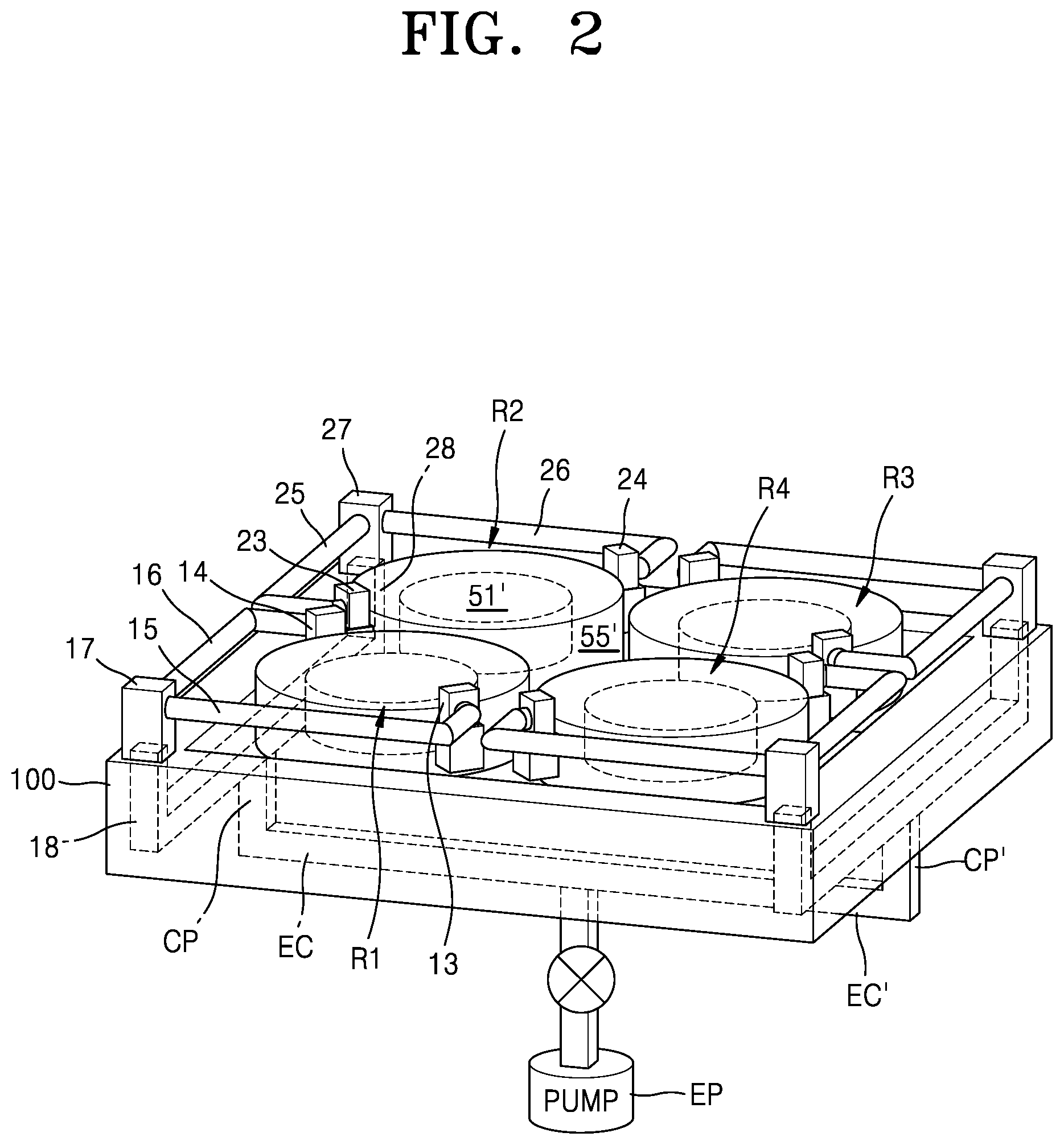
[0030] FIG. 2 is a view of a substrate processing device according to other embodiments of the inventive concept;
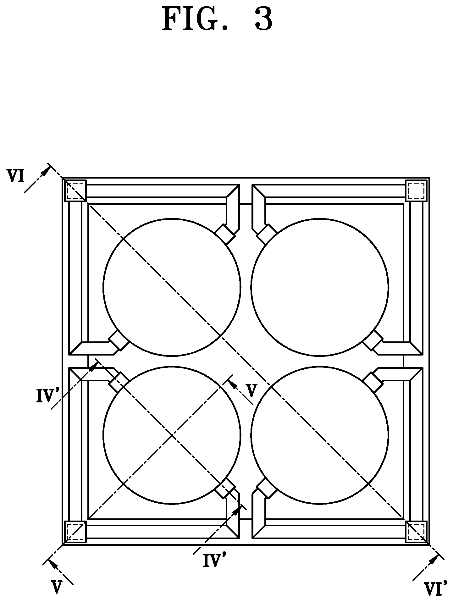
[0031] FIG. 3 is a plan view of the substrate processing device of FIG. 2;
[0032] FIGS. 4 to 6 are cross-sectional views of the substrate processing device of FIGS. 2 and 3;
[0033] FIG. 7 is a view of a substrate processing device according to some embodiments of the inventive concept;
[0034] FIG. 8 is a view of FIG. 7 viewed from a first direction, and FIG. 9 is a view of FIG. 7 viewed from a second direction;
[0035] FIGS. 10 to 12 are views of a substrate processing device according to embodiments of the inventive concept;
[0036] FIGS. 13 to 15 are views of a substrate processing device according to embodiments of the inventive concept;
[0037] FIG. 16 is a plan view of a substrate processing device according to embodiments of the inventive concept, in which an exhaust flow of the substrate processing device is shown; and
[0038] FIG. 17 is a view of a substrate processing device according to embodiments of the inventive concept.
DETAILED DESCRIPTION
[0039] Hereinafter, embodiments of the present disclosure will be described in detail with reference to the accompanying drawings.
[0040] In this regard, the present embodiments may have different forms and should not be construed as being limited to the descriptions set forth herein. Rather, these embodiments are provided so that the present disclosure will be thorough and complete, and will fully convey the scope of the present disclosure to one of ordinary skill in the art.
[0041] The terminology used herein is for the purpose of describing particular embodiments and is not intended to limit the present disclosure. As used herein, the singular forms "a", "an", and "the" are intended to include the plural forms as well, unless the context clearly indicates otherwise. It will be further understood that the terms "includes", "comprises" and/or "including", "comprising" used herein specify the presence of stated features, integers, steps, operations, members, components, and/or groups thereof, but do not preclude the presence or addition of one or more other features, integers, steps, operations, members, components, and/or groups thereof. As used herein, the term "and/or" includes any and all combinations of one or more of the associated listed items.
[0042] It will be understood that, although the terms first, second, etc. may be used herein to describe various members, components, regions, layers, and/or sections, these members, components, regions, layers, and/or sections should not be limited by these terms. These terms do not denote any order, quantity, or importance, but rather are only used to distinguish one component, region, layer, and/or section from another component, region, layer, and/or section. Thus, a first member, component, region, layer, or section discussed below could be termed a second member, component, region, layer, or section without departing from the teachings of embodiments.
[0043] Embodiments of the present disclosure will be described hereinafter with reference to the drawings in which embodiments of the present disclosure are schematically illustrated. In the drawings, variations from the illustrated shapes may be expected as a result of, for example, manufacturing techniques and/or tolerances. Thus, the embodiments of the present disclosure should not be construed as being limited to the particular shapes of regions illustrated herein but may include deviations in shapes that result, for example, from manufacturing processes.
[0044] FIG. 1 is a view of a substrate processing device according to embodiments of the inventive concept.
[0045] Referring to FIG. 1, the substrate processing device may include a first reactor R1, a first exhaust port 13, a second exhaust port 14, a first exhaust path 15, a second exhaust path 16, and a first transfer port 17.
[0046] The first reactor R1 may be a space in which processing is performed on an object to be processed such as a substrate. Although only one reactor is shown in FIG. 1, a plurality of reactors may be implemented. The reactor may provide a space for performing heating, deposition, etching, polishing, ion implantation, and/or other processing on the object to be processed.
[0047] For example, the reactor may be configured to perform a moving function, a vacuum sealing function, a heating function, an exhaust function, and/or other functions for the object to be processed such that the object is processed in the reactor. For example, the reactor may include a reaction space 51 for processing an object to be processed such as a substrate, and an exhaust space 55 for exhausting gas of the reaction space 51.
[0048] In an alternative embodiment, the exhaust space 55 may extend to surround the reaction space 51. In another alternative embodiment, the reactor may include at least one lid structure, and the exhaust space 55 and/or the reaction space 51 may be formed through the lid structure. In another alternative embodiment, the reactor may include a first lid and a second lid. In this case, the exhaust space 55 may be formed in the first lid and a processing unit (e.g., a gas supply unit) for reaction may be formed in the second lid (see FIG. 4).
[0049] The first exhaust port 13 may be configured to be in communication with the exhaust space 55. In an embodiment, the first exhaust port 13 may be configured to be in communication with a first portion of the exhaust space 55 formed to surround the reaction space 51. The first exhaust port 13 may connect one end of the first exhaust path 15 with the exhaust space 55. In an alternative embodiment, gas in the exhaust space 55 may be exhausted upwardly through the first exhaust port 13 to the first exhaust path 15. This upward exhaust may be achieved through a channel structure inside the first exhaust port 13. For example, a portion of the channel structure of the first exhaust port 13 may be in communication with the exhaust space 55 in a side direction, and the other portion of the channel structure of the first exhaust port 13 may be in communication with the first exhaust path 15 in an upward direction. Therefore, an L-shaped or L-like shaped channel may be formed in the first exhaust port 13.
[0050] The second exhaust port 14 may be configured to be in communication with the exhaust space 55. In an embodiment, the second exhaust port 14 may be configured to be in communication with a second portion of the exhaust space 55 formed to surround the reaction space 51. The second exhaust port 14 may connect one end of the second exhaust path 16 with the exhaust space 55. In an alternative embodiment, gas in the exhaust space 55 may be exhausted upwardly through the second exhaust port 14 to the second exhaust path 16. This upward exhaust may be achieved through a channel structure inside the second exhaust port 14. For example, a portion of the channel structure of the second exhaust port 14 may be in communication with the exhaust space 55 in a side direction, and the other portion of the channel structure of the second exhaust port 14 may be in communication with the second exhaust path 16 in an upward direction. Therefore, an L-shaped or L-like shaped channel may be formed in the second exhaust port 14.
[0051] In an alternative embodiment, the first exhaust port 13 and the second exhaust port 14 may be arranged symmetrically. For example, the first exhaust port 13 and the second exhaust port 14 may be arranged to face each other in a direction opposite to each other with an interval of 180 degrees. In another embodiment, in addition to the first exhaust port 13 and the second exhaust port 14, an additional exhaust port may be provided, and these may be arranged at the same angular interval (see FIG. 16).
[0052] The first exhaust path 15 may be connected between the first exhaust port 13 and the first transfer port 17. One end of the first exhaust path 15 may be connected to the first exhaust port 13 and the other end of the first exhaust path 15 may be connected to the first transfer port 17. Therefore, a portion of the gas in the reaction space 51 may be exhausted through the first exhaust port 13, the first exhaust path 15, and the first transfer port 17. In an alternative embodiment, the first exhaust path 15 may extend to surround a portion of the exhaust space 55. When the first exhaust port 13 has a channel structure for upward exhaust, the first exhaust path 15 may be above the exhaust space 55 of the first reactor R1. In another alternative embodiment, the first exhaust path 15 may be arranged outside a partition wall (not shown).
[0053] The second exhaust path 16 may be connected between the second exhaust port 14 and the first transfer port 17. One end of the second exhaust path 16 may be connected to the second exhaust port 14 and the other end of the second exhaust path 16 may be connected to the first transfer port 17. Therefore, another portion of the gas in the reaction space 51 may be exhausted through the second exhaust port 14, the second exhaust path 16, and the first transfer port 17. In an alternative embodiment, the second exhaust path 16 may extend to surround a portion of the exhaust space 55. When the second exhaust port 14 has a channel structure for upward exhaust, the second exhaust path 16 may be above the exhaust space 55 of the first reactor R1. In another alternative embodiment, the second exhaust path 16 may be arranged outside a partition wall (not shown).
[0054] The first transfer port 17 may be configured to connect the first exhaust path 15 with the second exhaust path 16. The first transfer port 17 may be configured to exhaust gas of the first exhaust path 15 and gas of the second exhaust path 16. For example, the first transfer port 17 may be connected to a first transfer path 18, and the gas of the first exhaust path 15 and the gas of the second exhaust path 16 may be exhausted to the first transfer path 18 through the first transfer port 17. In an alternative embodiment, the above-described exhaust may be downward exhaust, and such downward exhaust may be achieved through a channel structure inside the first transfer port 17. For example, a first portion of the channel structure of the first transfer port 17 may be in communication with the first exhaust path 15 in a first side direction, a second portion of the channel structure of the first transfer port 17 may be in communication with the second exhaust path 16 in a second side direction, and a third portion of the channel structure of the first transfer port 17 may be in communication with the first transfer path 18 in a downward direction. Therefore, a T-shaped or a T-like shaped channel may be formed in the first exhaust port 13.
[0055] In the substrate processing device having such an exhaust structure, a gas flow and an exhaust flow in a reactor may be uniformly controlled by providing a plurality of exhaust ports around the reaction space 51.
[0056] Alternatively, the exhaust ports may be arranged asymmetrically for a more efficient and uniform exhaust flow in the reactor. Optimized arrangement of the exhaust ports may be determined empirically or by simulation evaluation.
[0057] In an alternative embodiment, the substrate processing device may further include a partition wall (not shown) that accommodates the first reactor R1. In this case, the first transfer path 18 may be arranged in the partition wall. Such an arrangement structure of the first transfer path 18 has a technical advantage that an exhaust structure may be simplified in a multi-reactor structure in which substrate processing for a plurality of reactors is performed at the same time. This will be described later below in detail with reference to FIGS. 2 and 3.
[0058] FIG. 2 is a view of a substrate processing device according to other embodiments of the inventive concept. FIG. 3 is a plan view of the substrate processing device. The substrate processing device according to the embodiments may be a variation of the above-described substrate processing device according to the embodiments. Hereinafter, repeated descriptions of the embodiments will not be given herein.
[0059] The substrate processing device may be a multi-reactor device including a plurality of reactors. That is, the first reactor R1 and a second reactor R2 may be included in one substrate processing device so that a plurality of substrates may be processed at one time. Although four reactors are shown in FIGS. 2 and 3, the present disclosure is not limited thereto, and the substrate processing device may include a plurality of reactors (i.e., two or more reactors).
[0060] Referring to FIGS. 2 and 3, the substrate processing device may include the first reactor R1, the first exhaust port 13, the second exhaust port 14, the first exhaust path 15, the second exhaust path 16, and the first transfer port 17. These components have been described in detail with reference to FIG. 1, and thus repeated descriptions thereof will not be given herein. In addition, the substrate processing device may further include the second reactor R2, a third exhaust port 23, a fourth exhaust port 24, a third exhaust path 25, a fourth exhaust path 26, and a second transfer port 27. The substrate processing device may further include corresponding exhaust ports, exhaust paths, and transfer port structures associated with a third reactor R3 and a fourth reactor R4.
[0061] The third exhaust port 23 may be configured to be in communication with an exhaust space 55' of the second reactor R2. In an embodiment, the third exhaust port 23 may be configured to be in communication with the exhaust space 55' formed to surround a reaction space 51' of the second reactor R2. The third exhaust port 23 may connect one end of the third exhaust path 25 with the exhaust space 55'. In an alternative embodiment, gas in the exhaust space 55' may be exhausted upwardly through the third exhaust port 23 to the third exhaust path 25. This upward exhaust may be achieved through a channel structure inside the third exhaust port 23. For example, a portion of the channel structure of the third exhaust port 23 may be in communication with the exhaust space 55' in a side direction, and the other portion of the channel structure of the third exhaust port 23 may be in communication with the third exhaust path 25 in an upward direction. Therefore, an L-shaped or L-like shaped channel may be formed in the third exhaust port 23.
[0062] The fourth exhaust port 24 may be configured to be in communication with the exhaust space 55' of the second reactor R2. In an embodiment, the fourth exhaust port 24 may be configured to be in communication with the exhaust space 55' formed to surround the reaction space 51' of the second reactor R2. The fourth exhaust port 24 may connect one end of the fourth exhaust path 26 with the exhaust space 55'. In an alternative embodiment, gas in the exhaust space 55' may be exhausted upwardly through the fourth exhaust port 24 to the fourth exhaust path 26. This upward exhaust may be achieved through a channel structure inside the fourth exhaust port 24. For example, a portion of the channel structure of the fourth exhaust port 24 may be in communication with the exhaust space 55' in a side direction, and the other portion of the channel structure of the fourth exhaust port 24 may be in communication with the fourth exhaust path 26 in an upward direction. Therefore, an L-shaped or L-like shaped channel may be formed in the fourth exhaust port 24.
[0063] In an alternative embodiment, the third exhaust port 23 and the fourth exhaust port 24 may be arranged symmetrically. In another embodiment, the third exhaust port 23 and the fourth exhaust port 24 may be arranged so as to be uniformly spaced apart from each other with respect to the center of the reactor. In another embodiment, the third exhaust port 23 and the fourth exhaust port 24 may be provided with a control valve, and the flow rate of gas passing through the exhaust port through the control valve may be controlled. The flow rate of gas may be controlled simultaneously or individually so that exhaust uniformity is optimized, and the flow rate exhausted through each exhaust port may be the same as or different from each other. This configuration of the control valve allows a gas flow and an exhaust flow in an asymmetric exhaust system to be controlled more precisely.
[0064] The third exhaust path 25 may be connected between the third exhaust port 23 and the second transfer port 27. One end of the third exhaust path 25 may be connected to the third exhaust port 23 and the other end of the third exhaust path 25 may be connected to the second transfer port 27. Therefore, a portion of gas in the reaction space 51' of the second reactor R2 may be exhausted through the third exhaust port 23, the third exhaust path 25, and the second transfer port 27. In an alternative embodiment, the third exhaust path 25 may extend to surround a portion of the exhaust space 55'. When the third exhaust port 23 has a channel structure for upward exhaust, the third exhaust path 25 may be above the exhaust space 55' of the second reactor R2. Furthermore, the third exhaust path 25 may be arranged outside a partition wall 100.
[0065] The fourth exhaust path 26 may be connected between the fourth exhaust port 24 and the second transfer port 27. One end of the fourth exhaust path 26 may be connected to the fourth exhaust port 24 and the other end of the fourth exhaust path 26 may be connected to the second transfer port 27. Therefore, another portion of the gas in the reaction space 51' may be exhausted through the fourth exhaust port 24, the fourth exhaust path 26, and the second transfer port 27. In an alternative embodiment, the fourth exhaust path 26 may extend to surround a portion of the exhaust space 55'. When the fourth exhaust port 24 has a channel structure for upward exhaust, the fourth exhaust path 26 may be above the exhaust space 55' of the second reactor R2. Furthermore, the fourth exhaust path 26 may be arranged outside the partition wall 100.
[0066] The second transfer port 27 may be configured to connect the third exhaust path 25 with the fourth exhaust path 26. The second transfer port 27 may be configured to exhaust gas of the third exhaust path 25 and gas of the fourth exhaust path 26. For example, the second transfer port 27 may be connected to a second transfer path 28, and the gas of the third exhaust path 25 and the gas of the fourth exhaust path 26 may be exhausted to the second transfer path 28 through the second transfer port 27. In an alternative embodiment, the above-described exhaust may be downward exhaust, and such downward exhaust may be achieved through a channel structure inside a transfer port. For example, a first portion of the channel structure of the second transfer port 27 may be in communication with the third exhaust path 25 in a first side direction, a second portion of the channel structure of the second transfer port 27 may be in communication with the fourth exhaust path 26 in a second side direction, and a third portion of the channel structure of the second transfer port 27 may be in communication with the second transfer path 28 in a downward direction. Therefore, a T-shaped or a T-like shaped channel may be formed in the second exhaust port 27.
[0067] The substrate processing device may be a multi-substrate processing device implementing a gas supply and exhaust structure for simultaneous processing of a plurality of substrates. For example, the multi-substrate processing device may be a horizontal batch type device capable of simultaneously processing a plurality of substrates. That is, a plurality of substrates arranged in the transverse direction may be processed simultaneously. In this case, the first reactor R1 and the second reactor R2 may function as an inner chamber for simultaneously processing a plurality of substrates. The substrate processing device may further include the partition wall 100 for accommodating the inner chamber (i.e., the first reactor R1 and the second reactor R2). The partition wall 100 may function as an outer chamber.
[0068] The substrate processing device may further include the first transfer path 18 and the second transfer path 28. The first transfer path 18 may connect the first transfer port 17 with a connection port CP to transfer gas of the first transfer port 17 to the connection port CP. The second transfer path 28 may connect the second transfer port 27 with the connection port CP to transfer gas of the second transfer port 27 to the connection port CP. The connection port CP may be connected to an exhaust pump EP through an external path EC, and the above-described gases may be exhausted to the outside by the exhaust pump EP. In an alternative embodiment, the connection port CP may be arranged inside or outside the partition wall 100. In another alternative embodiment, the external path EC may be arranged in the partition wall 100.
[0069] In an alternative embodiment, the connection port CP may be symmetrically arranged with respect to the substrate processing device. For example, as shown in FIGS. 2 and 3, a first connection port CP connected to the first transfer path 18 and the second transfer path 28, and a second connection port CP' connected to a third transfer path and a fourth transfer path may be symmetrically arranged with respect to a central portion of the substrate processing device.
[0070] In some embodiments, the external path EC and the exhaust pump EP may be symmetrically arranged with respect to the substrate processing device. For example, as shown in FIGS. 2 and 3, the first external path EC and the second external path EC' respectively connected to the first connection port CP and the second connection port CP' may be symmetrically arranged with respect to the center portion of the substrate processing device. Furthermore, the exhaust pump EP may be arranged at the center portion of the substrate processing device.
[0071] In another embodiment, the external path EC and the exhaust pump EP may be arranged asymmetrically with respect to the substrate processing device. For example, as shown in FIGS. 7 to 9, the first external path EC connected to the first connection port CP may extend below the partition wall 100 toward a first corner portion C1 of the outer chamber. In addition, the second external path EC' connected to the second connection port CP' may extend below the partition wall 100 toward a second corner portion C2 of the outer chamber. The exhaust pump EP may be arranged on one surface of the substrate processing device, for example, corresponding to the center between the first corner portion C1 and the second corner portion C2. The first external path EC may extend from the portion extending to the first corner portion C1 to the exhaust pump EP. Also, the second external path EC' may extend from the portion extending to the second corner portion C2 to the exhaust pump EP.
[0072] In the case of a multi-reactor device having such an asymmetrical exhaust system, the uniformity or symmetry of exhaust of gas flowing from the reactor to an exhaust pump depends on the position of the reactor in an outer chamber. According to embodiments of the inventive concept, a gas flow and an exhaust flow in a reactor may be controlled uniformly by providing an exhaust port, an exhaust path, a transfer port, a transfer path, a connection port, and an external path around a reaction space, and by configuring such components to be connected to an exhaust pump arranged asymmetrically with respect to a substrate processing device. Alternatively, a control valve may be added to the external path to achieve a uniform exhaust flow within each reactor.
[0073] In another alternative embodiment, the first transfer path 18 and the second transfer path 28 may be arranged in the partition wall 100 of the outer chamber. For example, the first transfer path 18 may be formed in the partition wall 100 of the outer chamber, and the first transfer port 17 arranged at the first corner portion C1 (of FIG. 7) of the partition wall 100 may be connected to the first transfer path 18. Similarly, the second transfer path 28 may be formed inside the partition wall 100 of the outer chamber, and the second transfer port 27 arranged at the second corner portion C2 (of FIG. 7) of the partition wall 100 may be connected to the second transfer path 28. The first transfer port 17 and the second transfer port 27 may extend downward from the corner of the partition wall 100, respectively. Selectively and additionally, the first transfer port 17 and the second transfer port 27 may extend downwardly along the surface of the partition wall 100, and then the first transfer path 18 and the second transfer path 28 may be connected to the connection port CP.
[0074] FIGS. 4 to 6 are cross-sectional views of the substrate processing device of FIGS. 2 and 3. FIG. 4 is a cross-sectional view taken along line IV-IV' of FIG. 3, FIG. 5 is a cross-sectional view taken along line V-V of FIG. 3, and FIG. 6 is a cross-sectional view taken along line VI-VI' of FIG. 3.
[0075] Referring to FIGS. 4 to 6, a reactor of the substrate processing device may include a substrate supporting unit 150, a first lid 110, and a second lid 120.
[0076] The first lid 110 is located on the substrate supporting unit 150 and covers the upper part of the reaction space 51, and may include a processing unit. The processing unit may be coupled (e.g., fixed) to the first lid 110 and members that perform appropriate functions depending on functions of the reactor may be employed. For example, when a reactor performs a deposition function, the processing unit of the first lid 110 may include a reactant supply (e.g., a showerhead assembly). In another embodiment, when the reactor performs a polishing function, the processing unit of the first lid 110 may include a polishing pad.
[0077] The second lid 120 may be between the first lid 110 and the partition wall 100. The second lid 120 may provide a space in which the processing unit connected to the first lid 110 is accommodated. Optionally, the second lid 120 may provide a portion of the space for an object to be processed. For example, when the reactor performs a deposition function, the reaction space 51 for deposition may be formed inside a side wall of the second lid 120, and the exhaust space 55 may be formed inside the second lid 120.
[0078] A top lid TLD may contact the second lid 120 to support the first lid 110 and the second lid 120. The top lid TLD may be supported by the partition wall 100. The top lid TLD may be between the partition wall 100 and a lid (particularly, the second lid 120). A gap E may be formed between the second lid 120 and a flow control ring (FCR). The gap E may serve as a channel between the first reaction space 51 and the first exhaust space 55. Therefore, the first reaction space 51 and the first exhaust space 55 may be in communication with each other through the channel.
[0079] Referring to FIG. 4, a portion of the second lid 120 may be in communication with the first exhaust port 13. Therefore, gas in a portion of the exhaust space 55 may be exhausted through the first exhaust port 13. In an example embodiment, the first exhaust port 13 may have an L-shaped or L-like shaped channel formed therein, so that gas in the exhaust space 55 flows in a side direction and is exhausted upward. The other portion of the second lid 120 may be in communication with the second exhaust port 14 (of FIG. 1). Therefore, gas in the other portion of the exhaust space 55 may be exhausted through the second exhaust port 14 (of FIG. 1).
[0080] Gas exhausted upward through the first exhaust port 13 may be exhausted in connection with the first exhaust path 15. As described above, the first exhaust path 15 may extend to surround at least a portion of the first exhaust space 55. Furthermore, as shown in FIGS. 1, 4, 5 and 6, the first exhaust path 15 may be connected to the first transfer port 17. Similarly, gas exhausted upward through the second exhaust port 14 may be exhausted in connection with the second exhaust path 16 (of FIG. 1). The second exhaust path 16 (of FIG. 1) may extend to surround the other portion of the first exhaust space 55, and as shown in FIGS. 1, 4, 5 and 6, the second exhaust path 16 may be connected to the first transfer port 17.
[0081] The first transfer port 17 may have a T-shaped or T-like shaped (e.g., Y-shaped) channel formed therein. Gas of the first exhaust path 15 may be introduced in the first transfer port 17 in a first direction (e.g., first side direction), and gas of the second exhaust path 16 may be introduced in the first transfer port 17 in a second direction (e.g., second side direction). Further, the gases introduced in the first direction and the second direction may be exhausted in a third direction (e.g., downward direction).
[0082] In an alternative embodiment, the FCR may be between the top lid TLD and the substrate supporting unit 150. The FCR is arranged on the top lid TLD and may be arranged to be slidable on the top lid TLD. The FCR may be spaced apart from the substrate supporting unit 150 to form a gap G and a pressure balance between the reaction space 51 and an inner space of an outer chamber may be controlled by adjusting the gap G.
[0083] In another alternative embodiment, three or more exhaust ports may be arranged. For example, as shown in FIG. 16, four exhaust ports may be arranged per reactor, and these four exhaust ports may be spaced apart from each other at intervals of 90 degrees. In other words, a plurality of exhaust ports may be arranged per reactor, and the plurality of exhaust ports may be spaced apart from each other at intervals of 360/n degrees. In this case, n is the number of the plurality of exhaust ports, and may be a natural number of 2 or more. Alternatively, the plurality of exhaust ports may be arranged asymmetrically to achieve an optimized uniform exhaust flow, and the intervals and angles may be determined through experiment and simulation evaluation.
[0084] In another embodiment, as shown in FIG. 17, a plurality of control valves may be installed in each of the plurality of exhaust ports. The plurality of control valves may be connected to the exhaust ports and configured to control the flow rate of gas passing through respective exhaust ports. For example, the plurality of control valves may individually control the flow rate of gas passing through an exhaust port located at a first distance from a transfer port to be less than the flow rate of gas passing through an exhaust port located at a second distance from the transfer port, the second distance being greater than the first distance. This configuration of the control valve allows a gas flow and an exhaust flow in an asymmetric exhaust system to be controlled more uniformly.
[0085] FIGS. 7 to 9 are views of a substrate processing device according to some embodiments of the inventive concept. In more detail, FIG. 7 shows a portion of the substrate processing device excluding a lid, an exhaust port, an exhaust path, and a transfer port (i.e., the transfer paths 18 and 28, the connection port CP and CP', the external path EC connected to an external pump, etc.). FIG. 8 is a view of FIG. 7 viewed from a first direction, and FIG. 9 is a view of FIG. 7 viewed from a second direction. The substrate processing device according to the embodiments may be a variation of the above-described substrate processing device according to the embodiments. Hereinafter, repeated descriptions of the embodiments will not be given herein.
[0086] Referring to FIGS. 7 to 9, the transfer paths 18 (18a and 18b) and 28 (28a and 28b) are formed in the partition wall 100. The transfer paths 18 and 28 are connected to the external path EC through the connection port CP and CP' and the external path EC is connected to a main exhaust path 211. Therefore, gas in a reaction space is exhausted to the exhaust pump EP via the transfer ports 17 and 27, the transfer paths 18 and 28, the external path EC, and the main exhaust path 211.
[0087] As shown in FIG. 8, two reactors R1a and R1b in a first direction share the internal transfer path 18 (18a and 18b) and the remaining two reactors in a direction (e.g., A', not shown) opposite to the first direction share the other internal transfer path 28 (28a and 28b). The two internal transfer paths 18, 28 are connected to an external path EC through respective connection ports CP. FIGS. 7, 8 and 9 show that the four reactors share the external path EC, the main exhaust path 211, and the exhaust pump EP. An isolation valve 210 may be added to the main exhaust path 211. Therefore, the exhaust pump EP may be protected from the outside atmosphere by the isolation valve 210 during a maintenance period. Further, a pressure control valve (e.g., a throttle valve) may be added to the main exhaust path 211. The outer path EC may be fixed so as not to move in close contact with a lower surface of the partition wall 100 of an outer chamber. In an alternative embodiment, the two internal transfer paths 18 and 28 may be connected to each other within a bottom wall of the partition wall 100 of the outer chamber and directly connected to the main exhaust path 211, without the external path EC.
[0088] FIGS. 10 to 12 are views of a substrate processing device according to embodiments of the inventive concept. The substrate processing device according to the embodiments may be a variation of the above-described substrate processing device according to the embodiments. Hereinafter, repeated descriptions of the embodiments will not be given herein.
[0089] FIG. 10 shows an upper surface of the multi-reactor chamber 311. A plurality of reactors 312 are arranged in the chamber 311 and one side of each of the reactors 312 is connected to an exhaust port 313. FIG. 10 shows that each of the reactors 312 is connected to each exhaust port 313.
[0090] FIG. 11 shows a side perspective view of the reactor 312. A reaction space of the reactor 312 may be defined as a space surrounded by a lid 314 having an exhaust duct, an FCR 315 arranged below the lid 314, and a gas supply (e.g., a showerhead (not shown)) arranged in an inner space surrounded by the lid 314, and a substrate heating device (e.g., a heating block (not shown)) arranged to face the gas supply.
[0091] The lid 314 and the FCR 315 may be spaced apart from each other to form a gap. A space of, for example, 1 mm may be formed therebetween and gas in the reaction space may be exhausted to an exhaust pump (not shown) via an exhaust space 316 and the exhaust port 313 inside the lid 314 through the gap (i.e., a separate space). The exhaust port 313 may include a channel for exhausting gas downward.
[0092] In FIGS. 10 to 12, an exhaust path of gas is indicated by an arrow. As can be seen from the drawings, the exhaust port 313 is arranged in a side portion of the reaction space so that the flow of exhaust gas around a substrate is not uniform and may be deviated to one side. This may result in a deterioration of the uniformity of a thickness of a thin film and a problem that characteristics of the thin film are not uniform depending on the position.
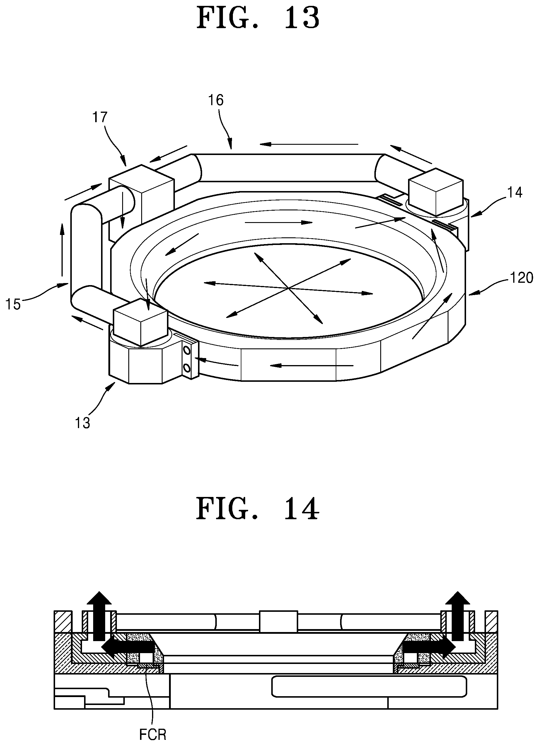
[0093] FIGS. 13 to 15 are views of a substrate processing device according to embodiments of the inventive concept. The substrate processing device according to the embodiments may be a variation of the above-described substrate processing device according to the embodiments. Hereinafter, repeated descriptions of the embodiments will not be given herein.
[0094] Referring to FIG. 13, the substrate processing device has the first exhaust port 13 and the second exhaust port 14 arranged at both ends of the second lid 120. The first exhaust port 13 and the second exhaust port 14 are connected to the first transfer port 17 through the first exhaust path 15 and the second exhaust path 16 respectively. The first transfer port 17 is connected to the transfer path 18 or 28 (of FIG. 8) inserted inside the partition wall 100 (of FIG. 8). An exhaust sequence to the exhaust pump EP (of FIG. 8) thereafter is the same as those described in FIGS. 8 and 9.
[0095] According to an exhaust configuration of FIGS. 13 and 14, gas in a reactor may be uniformly exhausted in both directions through the first exhaust port 13 and the second exhaust port 14 without being deviated to one side and exhausted. In more detail, gas exhausted through a separate space between the second lid 120 and the FCR is exhausted upward in both directions through the first exhaust port 13 and the second exhaust port 14. Thereafter, the gas is transferred to the first transfer port 17 through the first exhaust path 15 and the second exhaust path 16, and the gas is exhausted downward through the first transfer port 17. The downwardly evacuated gas is exhausted to the exhaust pump EP through the internal transfer path 18 or 28 in a chamber wall, the connection port CP, the external path EC, and the main exhaust path 211. In FIG. 14, the two exhaust ports 13 and 14 are provided in both directions of the second lid 120, but more uniform exhaust efficiency may be achieved in the reactor by providing additional exhaust ports as shown in FIG. 16.
[0096] FIG. 15 is a plan view of a multi-reactor chamber to which the reactor according to FIG. 14 is applied and shows an exhaust flow thereof.
[0097] Referring to FIGS. 13 to 15 and 7, the gas exhausted from the reaction space passes through the first exhaust port 13 connected to the lid 120, the second exhaust port 14 connected to the lid 120, the first exhaust path 15, the second exhaust path 16, and the first transfer port 17. Thereafter, the gas is exhausted to the exhaust pump EP via the transfer paths 18 or 28, the connection port CP, the external path EC, and the main exhaust path 211. FIG. 15 shows a gas flow 20 exhausted through an exhaust space 120 to the first exhaust port 13 and the second exhaust port 14, and a gas flow 21 exhausted through the first exhaust path 15 and the second exhaust path 16 to the first transfer port 17.
[0098] According to embodiments of the inventive concept, as shown in FIG. 7, two reactors share one set of the internal transfer paths 18a and 18b and the remaining two reactors share another set of the internal transfer paths 28a and 28b. The two internal transfer paths 18 and 28 of different sets share the external path EC, the main exhaust path 211, and the exhaust pump EP.
[0099] According to FIG. 13, two exhaust ports 13 and 14 are provided in the lid 120. However, the present disclosure is not limited thereto, and an exhaust port may be additionally provided to increase the uniformity of exhaust efficiency. FIG. 16 shows a modified embodiment of another exhaust system according to embodiments of the inventive concept which may achieve such the uniformity of exhaust efficiency.
[0100] Referring to FIG. 16, four exhaust ports, that is, the first exhaust port 13, the second exhaust port 14, the third exhaust port 23, and the fourth exhaust port 24 are connected to the exhaust duct 161. The first and fourth exhaust ports 13 and 24 are connected to an exhaust duct 161 (the lid 120 of FIG. 13) surrounding the reaction space and an external exhaust path 167, and one side surface of the external exhaust path 167 is connected to the first transfer port 17. The first transfer port 17 is connected to a transfer path (see the internal transfer path 18 or 28 of FIG. 7) formed within a chamber wall. Through this structure of FIG. 16, more uniform exhaust may be achieved in the reaction space.
[0101] In FIG. 16, four exhaust ports are connected to the exhaust duct 161, but the present disclosure is not limited thereto, and the exhaust ports may be arranged to be symmetrical with respect to the center of the exhaust duct 161. For example, 2, 3, 4, 5, 6, . . . n exhaust ports may be arranged at uniform intervals. In this case, arrangement angles between the exhaust ports are 180 degrees (n=2), 120 degrees (n=3), 90 degrees (n=4), 72 degrees (n=5), 60 degrees (n=6), . . . , 360/n degrees. In this case, n is the number of the plurality of exhaust ports, and may be a natural number of 2 or more.
[0102] Alternatively, the exhaust ports may be arranged asymmetrically for a more efficient and uniform exhaust flow in the reactor. Optimized arrangement of the exhaust ports may be determined empirically or by simulation evaluation.
[0103] FIG. 17 shows a substrate processing device that enables more uniform exhaust flow, which is a modified embodiment of the substrate processing device according to the embodiment of FIG. 16.
[0104] Referring to FIG. 17, control valves are connected to exhaust ports, respectively. A first control valve 168 is arranged between the first exhaust port 13 and the exhaust duct 161 and a second control valve 169 is arranged between the second exhaust port 14 and the exhaust duct 161. Similarly, a third control valve 170 and a fourth control valve 171 are arranged between the third exhaust port 23 and the exhaust duct 161 and between the fourth exhaust port 24 and the exhaust duct 161, respectively. The control valves allow more precise control of the exhaust efficiency of gases exhausted to the external exhaust path 167 in a reaction space, thereby enabling more uniform and efficient exhaust. Further, through the control valves, a more uniform gas flow may be achieved in the reaction space.
[0105] In the substrate processing device of FIG. 17, by respectively controlling an opening and closing sequence, speed, or a cross-sectional area of a gas flow path of each of the control valves, a uniform gas flow may be realized inside the reaction space, and the problem of a non-uniform gas flow due to asymmetricaled arrangement of the exhaust ports may be solved.
[0106] For example, opening and closing speeds of the first control valve 168 and the fourth control valve 171 respectively connected to the first exhaust port 13 and fourth exhaust port 24 close to the first transfer port 17 and a cross-sectional area of a gas flow path inside each of the control valves may be set to first values, and opening and closing speeds of the second control valve 169 and the third control valve 170 respectively connected to the second exhaust port 14 and the third exhaust port 23 relatively far from the first transfer port 17 and a cross-sectional area of a gas flow path inside each of the control valves may be set to second values different from the first values. Through these configurations, the gas flow in a reactor and the uniformity may be artificially controlled. That is, in a multi-reactor device having an asymmetrically arranged exhaust system, a gas flow and exhaust flow in the reactor may be artificially controlled to be more uniform. As a result, reproducible process implementations during a reaction period may be achieved.
[0107] Shapes of each portion of accompanying drawings for a clear understanding of the present disclosure should be considered in descriptive sense, but may be modified into various shapes other than those shown.
[0108] It should be understood that embodiments described herein should be considered in a descriptive sense only and not for purposes of limitation. Descriptions of features or aspects within each embodiment should typically be considered as available for other similar features or aspects in other embodiments.
[0109] While one or more embodiments have been described with reference to the figures, it will be understood by those of ordinary skill in the art that various changes in form and details may be made therein without departing from the spirit and scope of the disclosure as defined by the following claims.
* * * * *
D00000
D00001
D00002
D00003
D00004
D00005
D00006
D00007
D00008
D00009
D00010
D00011
D00012

D00013

XML
uspto.report is an independent third-party trademark research tool that is not affiliated, endorsed, or sponsored by the United States Patent and Trademark Office (USPTO) or any other governmental organization. The information provided by uspto.report is based on publicly available data at the time of writing and is intended for informational purposes only.
While we strive to provide accurate and up-to-date information, we do not guarantee the accuracy, completeness, reliability, or suitability of the information displayed on this site. The use of this site is at your own risk. Any reliance you place on such information is therefore strictly at your own risk.
All official trademark data, including owner information, should be verified by visiting the official USPTO website at www.uspto.gov. This site is not intended to replace professional legal advice and should not be used as a substitute for consulting with a legal professional who is knowledgeable about trademark law.