Methods Of Operating An Automated Machine For Inserting Wires Into Grommet Cavity Locations Of An Electrical Connector
Helmick; Eerik J. ; et al.
U.S. patent application number 16/840761 was filed with the patent office on 2020-07-23 for methods of operating an automated machine for inserting wires into grommet cavity locations of an electrical connector. This patent application is currently assigned to The Boeing Company. The applicant listed for this patent is The Boeing Company. Invention is credited to Nick S. Evans, Eerik J. Helmick, Bradley J. Mitchell.
| Application Number | 20200233404 16/840761 |
| Document ID | / |
| Family ID | 58448249 |
| Filed Date | 2020-07-23 |


| United States Patent Application | 20200233404 |
| Kind Code | A1 |
| Helmick; Eerik J. ; et al. | July 23, 2020 |
METHODS OF OPERATING AN AUTOMATED MACHINE FOR INSERTING WIRES INTO GROMMET CAVITY LOCATIONS OF AN ELECTRICAL CONNECTOR
Abstract
A method of operating an automated machine is provided for inserting wires into grommet cavity locations of an electrical connector to compensate for manufacturing tolerances associated with the electrical connector. The method comprises inserting wires into grommet cavity locations of the electrical connector based upon a plug map having offset values to compensate for manufacturing tolerances associated with the electrical connector. The method may further comprise selecting from a plurality of pre-generated plug maps having offset values the closest matching pre-generated plug map for the electrical connector based upon offset values associated with each of the plurality of pre-generated plugs maps. The selected pre-generated plug map having offset values corresponds to the plug map used to insert wires into grommet cavity locations of the electrical connector.
| Inventors: | Helmick; Eerik J.; (Everett, WA) ; Mitchell; Bradley J.; (Snohomish, WA) ; Evans; Nick S.; (Lynnwood, WA) | ||||||||||
| Applicant: |
|
||||||||||
|---|---|---|---|---|---|---|---|---|---|---|---|
| Assignee: | The Boeing Company Chicago IL |
||||||||||
| Family ID: | 58448249 | ||||||||||
| Appl. No.: | 16/840761 | ||||||||||
| Filed: | April 6, 2020 |
Related U.S. Patent Documents
| Application Number | Filing Date | Patent Number | ||
|---|---|---|---|---|
| 15137556 | Apr 25, 2016 | 10649442 | ||
| 16840761 | ||||
| Current U.S. Class: | 1/1 |
| Current CPC Class: | G05B 2219/45033 20130101; H01R 43/20 20130101; Y10S 901/02 20130101; G05B 19/41805 20130101; B25J 9/1687 20130101; G05B 2219/39183 20130101; G05B 2219/45064 20130101; H01R 2107/00 20130101 |
| International Class: | G05B 19/418 20060101 G05B019/418; B25J 9/16 20060101 B25J009/16; H01R 43/20 20060101 H01R043/20 |
Claims
1. An automated wire insertion machine for inserting wires into grommet cavity locations of an electrical connector, the automated wire insertion machine comprising: a controllable wire insertion robot; and a processing unit configured to control the controllable wire insertion robot based upon a plug map having offset values to insert wires into the grommet cavity locations of the electrical connector.
2. The automated wire insertion machine according to claim 1 further comprising: a data storage unit configured to store the plug map having offset values.
3. The automated wire insertion machine according to claim 2 wherein the plug map having offset values comprises one of a plurality of pre-generated plug maps associated with the electrical connector.
4. The automated wire insertion machine according to claim 3 wherein the one of the plurality of pre-generated plug maps comprises the closest matching pre-generated plug map for the electrical connector based upon offset values associated with each of the plurality of pre-generated plugs maps.
5. The automated wire insertion machine according to claim 3 wherein the plurality of pre-generated plug maps are generated based upon an original plug map of the grommet cavity locations of the electrical connector.
6. The automated wire insertion machine according to claim 5 wherein the plurality of pre-generated plug maps are generated by the processing unit.
7. The automated wire insertion machine according to claim 6 wherein the plurality of pre-generated plug maps are generated by defining a range of potential error of the grommet cavity locations of the electrical connector that comprises at least one of a potential rotational error and a potential translational error.
8. The automated wire insertion machine according to claim 7 wherein the plurality of pre-generated plug maps are generated by defining an acceptable tolerance of the grommet cavity locations of the electrical connector that comprises at least one of an acceptable rotational tolerance and an acceptable translational tolerance.
9. The automated wire insertion machine according to claim 8 wherein the plurality of pre-generated plug maps are generated by calculating all permutations of possible offset values of the grommet cavity locations of the electrical connector based on the range of potential error and the acceptable tolerance, thereby creating the plurality of pre-generated plug maps.
10. The automated wire insertion machine according to claim 9 wherein the controllable wire insertion robot inserts the wires into the grommet cavity locations of the electrical connector based upon one pre-generated plug map of the plurality of pre-generated plug maps.
11. The automated wire insertion machine according to claim 6 wherein the plurality of pre-generated plug maps are generated by defining a range of potential error of the grommet cavity locations of the electrical connector that comprises both a potential rotational error and a potential translational error.
12. The automated wire insertion machine according to claim 11 wherein the plurality of pre-generated plug maps are generated by defining an acceptable tolerance of the grommet cavity locations of the electrical connector that comprises both an acceptable rotational tolerance and an acceptable translational tolerance.
13. The automated wire insertion machine according to claim 12 wherein the plurality of pre-generated plug maps are generated by calculating all permutations of possible offset values of the grommet cavity locations of the electrical connector based on the range of potential error and the acceptable tolerance, thereby creating the plurality of pre-generated plug maps.
14. The automated wire insertion machine according to claim 13 wherein the controllable wire insertion robot inserts the wires into the grommet cavity locations of the electrical connector based upon one pre-generated plug map of the plurality of pre-generated plug maps.
15. The automated wire insertion machine according to claim 1 further comprising: a data storage unit configured to store an original plug map associated with the electrical connector.
16. The automated wire insertion machine according to claim 15 wherein the offset values have been received from a source external to the automated wire insertion machine.
17. The automated wire insertion machine according to claim 16 wherein the processing unit is further configured to calculate the plug map having offset values based upon the original plug map stored in the data storage unit and the offset values that have been received from the source external to the automated wire insertion machine.
18. The automated wire insertion machine according to claim 1 wherein the offset values comprise at least one of rotational offset values and translational offset values.
19. A method of operating an automated machine for inserting wires into grommet cavity locations of an electrical connector to compensate for manufacturing tolerances associated with the electrical connector, the method comprising: storing in a data storage unit a plurality of pre-generated plug maps associated with the electrical connector; retrieving from the data storage unit one of the plurality of pre-generated plug maps; and inserting wires into grommet cavity locations of the electrical connector based upon the retrieved one of the plurality of pre-generated plug maps to compensate for manufacturing tolerances associated with the electrical connector.
20. A method of operating an automated machine for inserting wires into grommet cavity locations of an electrical connector to compensate for manufacturing tolerances associated with the electrical connector, the method comprising: storing in a data storage unit local to the automated wire insertion machine an original plug map associated with the electrical connector; receiving offset values from a source external to the automated wire insertion machine; calculating an updated plug map based upon the original plug map and the offset values; and inserting wires into grommet cavity locations of the electrical connector based upon the updated plug map to compensate for manufacturing tolerances associated with the electrical connector.
Description
PRIORITY
[0001] This application is a divisional of U.S. Ser. No. 15/137,556 filed on Apr. 25, 2016.
FIELD
[0002] The present application relates to wire insertion machines, and is particularly directed to methods of operating an automated machine for inserting wires into grommet cavity locations of an electrical connector and an automated wire insertion machine.
BACKGROUND
[0003] A typical wire insertion machine includes a robot that inserts wires into grommet cavity locations of an electrical connector. The electrical connector is mounted on a mounting fixture that is firmly affixed to a base of the wire insertion machine. The wire insertion machine also includes a processing unit that controls the robot to insert wires in accordance with a plug map and program instructions stored in a data storage unit. The plug map comprises spatial coordinates at which the robot is to insert wires into grommet cavity locations of the electrical connector.
[0004] A drawback in the operation of the above-described wire insertion machine is that one or more spatial coordinates at which the robot is to insert wires may not align sufficiently with the corresponding true grommet cavity locations of the electrical connector to ensure successful wire insertions. A failed wire insertion occurs when spatial coordinates at which the wire is to be inserted do not align sufficiently with the corresponding true grommet cavity location. It would be desirable to overcome such drawbacks in the operation of wire insertion machines.
SUMMARY
[0005] In one aspect, a method of operating an automated machine is provided for inserting wires into grommet cavity locations of an electrical connector to compensate for manufacturing tolerances associated with the electrical connector. The method comprises inserting wires into grommet cavity locations of the electrical connector based upon a plug map having offset values to compensate for manufacturing tolerances associated with the electrical connector.
[0006] In another aspect, a method of operating an automated machine is provided for inserting wires into grommet cavity locations of an electrical connector to compensate for manufacturing tolerances associated with the electrical connector. The method comprises storing in a data storage unit a plurality of pre-generated plug maps associated with the electrical connector. The method further comprises retrieving from the data storage unit one of the plurality of pre-generated plug maps. The method also comprises inserting wires into grommet cavity locations of the electrical connector based upon the retrieved one of the plurality of pre-generated plug maps to compensate for manufacturing tolerances associated with the electrical connector.
[0007] In another aspect, a method of operating an automated machine is provided for inserting wires into grommet cavity locations of an electrical connector to compensate for manufacturing tolerances associated with the electrical connector. The method comprises storing in a data storage unit local to the automated wire insertion machine an original plug map associated with the electrical connector. The method further comprises receiving offset values from a source external to the automated wire insertion machine. The method further comprises calculating an updated plug map based upon the original plug map and the offset values. The method also comprises inserting wires into grommet cavity locations of the electrical connector based upon the updated plug map to compensate for manufacturing tolerances associated with the electrical connector.
[0008] In yet another aspect, an automated wire insertion machine is provided for inserting wires into grommet cavity locations of an electrical connector. The automated wire insertion machine comprises a controllable wire insertion robot, and a processing unit configured to control the wire insertion robot based upon a plug map having offset values to insert wires into the grommet cavity locations of the electrical connector.
[0009] Other aspects will become apparent from the following detailed description, the accompanying drawings and the appended claims.
BRIEF DESCRIPTION OF THE DRAWINGS
[0010] FIG. 1 is a block diagram of an example automated wire insertion machine constructed in accordance with an embodiment.
[0011] FIG. 2 shows an example computer system external to the automated wire insertion machine of FIG. 1 and capable of providing a plug map having offset values for use in the automated wire insertion machine.
[0012] FIG. 3 shows an example plug map having offset values for use in the automated wire insertion machine of FIG. 1.
[0013] FIG. 4 is a flow diagram depicting an example method of operating the example computer system of FIG. 2 to pre-generate plug maps having offset values in accordance with an embodiment.
[0014] FIG. 5 is a flow diagram depicting an example method of operating the example automated wire insertion machine of FIG. 1 in accordance with an embodiment.
[0015] FIG. 6 is a flow diagram depicting an example method of operating the computer system of FIG. 2 to provide a selected pre-generated plug map having offset values for the automated wire insertion machine of FIG. 1.
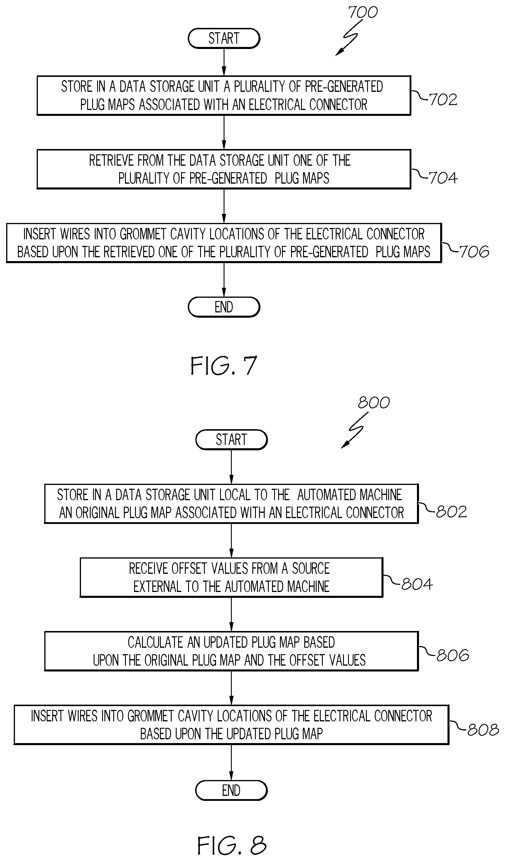
[0016] FIG. 7 is a flow diagram depicting an example method of operating the automated wire insertion machine of FIG. 1 in accordance with another embodiment.
[0017] FIG. 8 is a flow diagram depicting an example method of operating the automated wire insertion machine of FIG. 1 in accordance with yet another embodiment.
DETAILED DESCRIPTION
[0018] The present application is directed to methods of operating an automation machine for inserting wires into an electrical connector. The specific construction of the automated wire insertion machine and the industry in which the machine is implemented may vary. It is to be understood that the disclosure below provides a number of embodiments or examples for implementing different features of various embodiments. Specific examples of components and arrangements are described to simplify the present disclosure. These are merely examples and are not intended to be limiting.
[0019] By way of example, the disclosure below describes an automated wire insertion machine and methods implemented by the Boeing Corporation for insertion of wires in electrical connectors for airplane parts in compliance with Federal Aviation Administration (FAA) regulations.
[0020] Referring to FIG. 1, a block diagram of an example automated wire insertion machine 100 constructed in accordance with an embodiment is illustrated. An existing model of a wire insertion machine can be modified to provide automated wire insertion machine 100. For example, model Komax Zeta 656 manufactured by Komax located in Switzerland can be modified to provide automated wire insertion machine 100. Modifications of other models of wire insertion machines are possible.
[0021] Automated wire insertion machine 100 includes processing unit 102 that executes instructions stored in internal data storage unit 104, external data storage unit (not shown), or a combination thereof. Processing unit 102 may comprise any type of technology. For example, processing unit 102 may comprise a dedicated-purpose electronic processor. Other types of processors and processing unit technologies are possible. Internal data storage unit 104 may comprise any type of technology. For examples, internal data storage unit 104 may comprise random access memory (RAM), read only memory (ROM), solid state memory, or any combination thereof. Other types of memories and data storage unit technologies are possible.
[0022] Automated wire insertion machine 100 further includes a number of input/output (I/O) devices 106 that may comprise any type of technology. For example, I/O devices 106 may comprise a keypad, a keyboard, a touch-sensitive display screen, a liquid crystal display (LCD) screen, a microphone, a speaker, or any combination thereof. Other types of I/O devices and technologies are possible.
[0023] Automated wire insertion machine 100 further includes wire insertion robot 108 that is controlled in response to signals from processing unit 102. More specifically, processing unit 102 executes instructions of a wire insertion application program stored in data storage unit 104 to control operation of wire insertion robot 108 to insert wires into grommet cavity locations 110 of electrical connector 112 shown in FIG. 1. Electrical connector 112 may comprise a MIL-spec type of electrical connector, and is mounted on a fixture of automated wire insertion machine 100. Structure and operation of wire insertion robots are known and, therefore, will not be further described.
[0024] Referring to FIG. 2, an example computer system 200 external to automated wire insertion machine 100 of FIG. 1 and capable of providing a plug map having offset values (as will be described in more detail hereinbelow with reference to FIG. 3) for use in automated wire insertion machine 100 is illustrated. Computer system 200 includes processing unit 202 that executes instructions stored in internal data storage unit 204, external data storage unit (not shown), or a combination thereof. Processing unit 202 may comprise any type of technology. For example, processing unit 202 may comprise a general-purpose electronic processor. Other types of processors and processing unit technologies are possible. Internal data storage unit 204 may comprise any type of technology. For examples, internal data storage unit 204 may comprise random access memory (RAM), read only memory (ROM), solid state memory, or any combination thereof. Other types of memories and data storage unit technologies are possible.
[0025] Computer system 200 further includes a number of input/output (I/O) devices 206 that may comprise any type of technology. For example, I/O devices 206 may comprise a keypad, a keyboard, a touch-sensitive display screen, a liquid crystal display (LCD) screen, a microphone, a speaker, or any combination thereof. Other types of I/O devices and technologies are possible.
[0026] Referring to FIG. 3, an example plug map 300 having offset values for use in automated wire insertion machine 100 of FIG. 1 is illustrated. More specifically, example plug map 300 includes a first set of cavity locations 310 (shown as solid circles in FIG. 3) that correspond to original cavity locations for electrical connector 112 (FIG. 1). Each of the original cavity locations (i.e., each of the first set of cavity locations 310) corresponds to spatial coordinates at which automated wire insertion machine 100 attempts to insert a wire. Plug map 300 further includes a second set of cavity locations 320 (shown as dashed circles in FIG. 3) that are rotationally offset (i.e., angular offset) about center point 330 relative to the first set of cavity locations 310. Each of the angular offset cavity locations (i.e., each of the second set of cavity locations 320) corresponds to spatial coordinates at which automated wire insertion machine 100 attempts to insert a wire in accordance with example embodiments as will be described in detail hereinbelow.
[0027] Referring to FIG. 4, flow diagram 400 depicts an example method of operating the example computer system of FIG. 2 to pre-generate plug maps having offset values in accordance with an embodiment. In block 402, an original plug map of an electrical connector, such as electrical connector 112 shown in FIG. 1, is obtained. The original plug map contains data that represents spatial coordinates corresponding to the centroid of each of grommet cavity locations of an ideally-manufactured electrical connector. This data can be obtained, for example, from the manufacturer of electrical connector 112. The process then proceeds to block 404.
[0028] In block 404, a range of potential rotational error for electrical connector 112 is defined. For example, the range of potential rotational error may be defined as .+-.3.0 degrees. In block 406, an acceptable rotational tolerance is defined. For example, the rotational tolerance may be defined as 0.1 degrees. The process then proceeds to block 408.
[0029] In block 408, all permutations of possible rotational offset values are calculated and defined based upon the range of potential error defined in block 404 and the acceptable rotational tolerance defined in block 406. Then, in block 410, plug maps having offset values (such as plug map 300 having offset values shown in FIG. 3) are created based upon the original plug map obtained in block 402 and the permutations of possible rotational offset values defined in block 408. Given the example range of potential rotational error of .+-.3.0 degrees and the example acceptable rotational tolerance of 0.1 degrees, this would result in sixty different plug maps with offset values (i.e., offset values of .+-.0.1.degree.; .+-.0.2.degree.; .+-.0.3.degree. . . . .+-.2.8.degree.; .+-.2.9.degree.;.+-.3.0.degree.).
[0030] As an example, new X coordinate portion of a coordinate pair is equal to cos(.theta.)X-sin(.delta.)Y. Each new Y coordinate portion of a coordinate pair is equal to sin(.theta.)X+cos(.theta.)Y. The angle .theta. is defined as the angle between zero and 360 degrees, or between zero and 2.pi. radians. Thus, in this example, there are a total of sixty-one plug maps (i.e., the original plug map and the sixty plug maps with offset values) associated with electrical connector 112. The process then proceeds to block 412.
[0031] In block 412, the total of sixty-one plug maps (i.e., the original plug map and the sixty pre-generated plug maps with offset values) associated with electrical connector 112 are stored locally in data storage unit 104 of automated wire insertion machine 100. It is conceivable that original plug maps and corresponding plug maps with offset values associated with other electrical connectors be stored locally in data storage unit 104 of automated wire insertion machine 100. The process then ends.
[0032] Referring to FIG. 5, flow diagram 500 depicts an example method of operating the example automated wire insertion machine 100 of FIG. 1 in accordance with an embodiment. In block 502, wires are inserted into grommet cavity locations 110 of electrical connector 112 (FIG. 1) based upon a plug map having offset values that is stored in data storage unit 104 of automated wire insertion machine 100. The process then ends.
[0033] Referring to FIG. 6, flow diagram 600 depicts an example method of operating computer system 200 of FIG. 2 to provide a selected pre-generated plug map having offset values for automated wire insertion machine 100 of FIG. 1. In this example embodiment, the original plug map and the plug maps with offset values that were pre-generated in FIG. 4 are also stored in data storage unit 202 of computer system 200 (FIG. 2). Flow diagram 600 shows a process to select the most closely matching pre-generated plug map.
[0034] In block 602, a measured plug map of electrical connector 112 shown in FIG. 1 is obtained. The measured plug map contains data that represents spatial coordinates corresponding to the centroid of each of grommet cavity locations 110 of electrical connector 112. This data can be obtained, for example, by a vision system (not shown) that captures an image of electrical connector 112. An example vision system that can be used to provide a measured plug map comprises model In-Sight 5605 manufactured by Cognex located in Natick, Mass., U.S.A. Vision software of vision system is trained to locate the true location of the centroid of each individual cavity. The true location of each cavity is provided in the same Cartesian coordinate system (X, Y) of the original plug map. The process then proceeds to block 604.
[0035] In block 604, the offset between the measured plug map and each of the pre-generated plug maps is calculated on an individual cavity-by-cavity basis. Then, in block 606, for each pre-generated plug map, the sum of offset values associated with that particular pre-generated plug map is calculated. More specifically, the distance formula represented as follows is used to calculate each offset value.
Offset Value=[(X.sub.2-X.sub.1).sup.2+(Y.sub.2-Y.sub.1).sup.2].sup.1/2
[0036] where (X.sub.1, Y.sub.1) are the spatial coordinates of a point from the measured plug map; and
[0037] (X.sub.2, Y.sub.2) are the spatial coordinates of a point from a pre-generated plug map.
Each offset value is representative of the distance away from the true location of the associated grommet cavity location of electrical connector 112. This process is repeated for each of the cavities for each pre-generated plug map. A sum of all offset values associated with each pre-generated plug map is then obtained. Thus, sixty sum of offset values are provided. The process then proceeds to block 608.
[0038] In block 608, the pre-generated plug map with the smallest sum of offset values is selected. This selected pre-generated plug map is the closest match (i.e., the "best match" or "best fit") to the measured plug map obtained in block 602. Then, in block 610, the selected pre-generated plug map of block 608 is identified, for example, by its plug map number. The plug map number is provided to automated wire insertion machine 100 (FIG. 1) to allow machine 100 to retrieve the corresponding pre-generated plug map from data storage unit 104 to insert wires into grommet cavity locations 110 of electrical connector 112 based on the identified pre-generated plug map. The process of flow diagram 600 of FIG. 6 then ends.
[0039] Referring to FIG. 7, flow diagram 700 depicts an example method of operating the automated wire insertion machine 100 of FIG. 1 in accordance with another embodiment. In block 702, a plurality of pre-generated plug maps associated with electrical connector 112 is stored in data storage unit 104 of automated wire insertion machine 100. Then, in block 704, one of the pre-generated plug maps stored in data storage unit 104 is retrieved. In block 706, wires are inserted into grommet cavity locations 110 of electrical connector 112 based upon the pre-generated plug map retrieved in block 704. The process then ends.
[0040] Referring to FIG. 8, flow diagram 800 depicts an example method of operating the automated wire insertion machine of FIG. 1 in accordance with yet another embodiment. In block 802, an original plug map associated with electrical connector 112 is stored locally in data storage unit 104 of automated wire insertion machine 100. Then, in block 804, offset values are received from a source external to automated wire insertion machine 100. The offset values may be obtained by taking the difference for each point between an original plug map and a measured plug map, for example. The measured plug map can be obtained by a vision system, for example. The process proceeds to block 806.
[0041] In block 806, an updated plug map is calculated based upon an original plug map stored in data storage unit 104 and the offset values received in block 804. The updated plug map is stored in data storage unit 104. Then, in block 808, wires are inserted into grommet locations 110 of electrical connector 112 based upon the updated plug map of block 806. The process of flow diagram 800 of FIG. 8 then ends.
[0042] It should be apparent that the above-described plug maps with offset values enable automated insertion of wires into grommet cavity locations of an electrical connector to compensate for manufacturing tolerances associated with the electrical connector. Plug maps with offset values are needed to enable automated wire insertion because grommet cavity locations of electrical connectors do not have exact locations and dimensions. The offset values are needed to avoid collision of a wire with the electrical connector when the wire is being inserted. Wires are inserted with a much lower risk of a failed wire insertion.
[0043] It should also be apparent that the stored permutations of offset values enable a fast robotic insertion of wires into grommet cavity locations of the electrical connector. While a large number of pre-generated plug maps with offset values would be difficult to search through manually, it would be relatively easy to use a processing unit to search through the large number of pre-generated plug maps with offset values.
[0044] Although the above description describes rotational offset values, it is conceivable that translational offset values, or a combination of rotational offset values and translational offset values be used.
[0045] Also, although the above description describes sixty plug maps having offset values being pre-generated, it is conceivable that any number of plug maps having offset values could be pre-generated. For examples, the number of plug maps having offset values could be hundreds, thousands, or even tens of thousands, depending upon the range of potential error and the acceptable tolerance for the particular application.
[0046] Further, although the above describes plug maps having offset values being used for automated wire insertion in grommet cavity locations of MIL-spec type of electrical connectors, it is conceivable that plug maps having offset values be used for automated insertion in grommet cavity locations of non-MIL-spec type of electrical connectors.
[0047] Although the above-description describes methods for facilitating automated wire insertion into grommet cavity locations of electrical connectors for airplane parts in the aviation industry in accordance with FAA regulation, it is contemplated that the methods may be implemented to facilitate automated wire insertion for any type of electrical connector in any industry in accordance with the applicable industry standards.
[0048] Aspects of disclosed embodiments may be implemented in software, hardware, firmware, or a combination thereof. The various elements of the system, either individually or in combination, may be implemented as a computer program product tangibly embodied in a machine-readable storage device for execution by a processor. Various steps of embodiments may be performed by a computer processor executing a program tangibly embodied on a computer-readable medium to perform functions by operating on input and generating output. The computer-readable medium may be, for example, a memory, a transportable medium such as a compact disk or a flash drive, such that a computer program embodying aspects of the disclosed embodiments can be loaded onto a computer.
[0049] Although various aspects of disclosed embodiments have been shown and described, modifications may occur to those skilled in the art upon reading the specification. The present application includes such modifications and is limited only by the scope of the claims.
* * * * *
D00000
D00001
D00002
D00003
D00004
D00005
XML
uspto.report is an independent third-party trademark research tool that is not affiliated, endorsed, or sponsored by the United States Patent and Trademark Office (USPTO) or any other governmental organization. The information provided by uspto.report is based on publicly available data at the time of writing and is intended for informational purposes only.
While we strive to provide accurate and up-to-date information, we do not guarantee the accuracy, completeness, reliability, or suitability of the information displayed on this site. The use of this site is at your own risk. Any reliance you place on such information is therefore strictly at your own risk.
All official trademark data, including owner information, should be verified by visiting the official USPTO website at www.uspto.gov. This site is not intended to replace professional legal advice and should not be used as a substitute for consulting with a legal professional who is knowledgeable about trademark law.