Lighting Assembly For Transparent Electronic Display And Graphic
Diaz; Marcos ; et al.
U.S. patent application number 16/839451 was filed with the patent office on 2020-07-23 for lighting assembly for transparent electronic display and graphic. The applicant listed for this patent is Manufacturing Resources International, Inc.. Invention is credited to Marcos Diaz, William Dunn.
| Application Number | 20200233265 16/839451 |
| Document ID | / |
| Family ID | 55655322 |
| Filed Date | 2020-07-23 |


| United States Patent Application | 20200233265 |
| Kind Code | A1 |
| Diaz; Marcos ; et al. | July 23, 2020 |
LIGHTING ASSEMBLY FOR TRANSPARENT ELECTRONIC DISPLAY AND GRAPHIC
Abstract
A transparent electronic display layer is placed between a front and rear transparent layer. A light guide is positioned behind the transparent electronic display layer and has an outer edge. Lighting elements are positioned adjacent to the outer edge. A cavity is positioned adjacent to and on an opposing side of the lighting elements as compared to the light guide such that light exiting the lighting elements enters both the light guide and the cavity. A graphic may be provided at the cavity.
| Inventors: | Diaz; Marcos; (Alpharetta, GA) ; Dunn; William; (Alpharetta, GA) | ||||||||||
| Applicant: |
|
||||||||||
|---|---|---|---|---|---|---|---|---|---|---|---|
| Family ID: | 55655322 | ||||||||||
| Appl. No.: | 16/839451 | ||||||||||
| Filed: | April 3, 2020 |
Related U.S. Patent Documents
| Application Number | Filing Date | Patent Number | ||
|---|---|---|---|---|
| 14878679 | Oct 8, 2015 | 10649273 | ||
| 16839451 | ||||
| 62061512 | Oct 8, 2014 | |||
| Current U.S. Class: | 1/1 |
| Current CPC Class: | G02B 6/0091 20130101; G02F 1/133603 20130101; G02B 6/0068 20130101; A47F 3/001 20130101; G02B 6/0085 20130101; A47F 11/10 20130101; A47F 3/0404 20130101; G02B 6/0041 20130101; A47F 3/043 20130101; A47F 3/0434 20130101 |
| International Class: | G02F 1/13357 20060101 G02F001/13357; F21V 8/00 20060101 F21V008/00; A47F 3/04 20060101 A47F003/04; A47F 11/10 20060101 A47F011/10 |
Claims
1. A display assembly comprising: a front transparent layer; a rear transparent layer; a transparent electronic display layer placed between the front transparent layer and the rear transparent layer; a light guide positioned behind the transparent electronic display layer; lighting elements positioned along an outer edge of the light guide; and a cavity positioned adjacent to, and on an opposing side of, the lighting elements as compared to the light guide such that light exiting the lighting elements enters both the light guide and the cavity.
2. The display assembly of claim 1 wherein: the transparent electronic display layer comprises liquid crystals.
3. The display assembly of claim 1 wherein: the front transparent layer comprises glass; and the rear transparent layer comprises glass.
4. The display assembly of claim 1 wherein: the plurality of lighting elements comprise light emitting diodes.
5. The display assembly of claim 1 further comprising: a graphic placed at the cavity.
6. The display assembly of claim 5 wherein: the cavity is configured to permit light entering the cavity to exit through the front transparent layer.
7. The display assembly of claim 6 further comprising: a reflective surface positioned within the cavity and between the graphic and the rear transparent layer.
8. The display assembly of claim 7 further comprising: a housing defining a storage cavity for a number of consumer products; and an access panel movably attached to said housing, wherein the front transparent layer and the rear transparent layer define, at least in part, front and rear surfaces of said access panel.
9. The display assembly of claim 8 further comprising: a refrigeration system for the housing configured to cool the number of consumer products, wherein the access panel is a door.
10. The display assembly of claim 1 further comprising: a thermal plate bonded to the rear transparent layer and in thermal communication with the plurality of lighting elements, wherein the plurality of lighting elements are attached to the thermal plate.
11. A method for illuminating a display case comprising the steps of: providing a transparent electronic display layer between a front transparent cover and a rear transparent cover, a light guide behind the transparent electronic display layer, lighting elements along an edge of the light guide, and a cavity adjacent to the lighting elements; placing a graphic within or adjacent to the cavity; providing electrical power to the lighting elements such that light is caused to enter both the light guide and the cavity, thereby illuminating both the graphic and the transparent electronic display layer; and causing images to be displayed at the transparent electronic display layer.
12. The method of claim 11 further comprising the steps of: providing a housing defining a storage cavity for a number of consumer products; and attaching an access panel to the housing in a moveable fashion, wherein said access panel comprises the transparent electronic display layer, the front transparent cover, the rear transparent cover, the light guide, the lighting elements, and the cavity.
13. The method of claim 12 wherein: the lighting elements, when supplied with electrical power, are configured to illuminate the number of consumer products within the housing.
14. The method of claim 12 further comprising the steps of: circulating refrigerated air within the housing to cool the number of consumer products.
15. The method of claim 13 further comprising the steps of: attaching a thermal plate to the rear transparent cover, wherein said thermal plate is in thermal communication with the lighting elements; conductively transferring heat from the lighting elements to the thermal plate; and conductively transferring heat from the thermal plate to the refrigerated air within the housing.
16. The method of claim 11 wherein: said transparent electronic display layer comprises a number of liquid crystals; and said lighting elements comprise light emitting diodes.
17. A display case comprising: a housing configured to hold a number of consumer products; and a door assembly moveably attached to the storage cavity and comprising: a front transparent layer; a rear transparent layer; a transparent electronic display layer configured to display images and positioned between a front transparent layer and a rear transparent layer; a light guide positioned behind the transparent electronic display and having an outer edge; lighting elements positioned along the outer edge of the light guide; a cavity positioned on an opposing side of the lighting elements as compared to the light guide; and a static graphic comprising artwork located within or adjacent to the cavity; wherein the lighting elements are configured to, when illuminated, simultaneously emit light to both the transparent electronic display layer and the static graphic such that the images displayed at the transparent electronic display and the artwork of the graphic are illuminated.
18. The display case of claim 17 wherein: the cavity is defined, at least in part, by the front transparent layer and the rear transparent layer.
19. The display case of claim 18 further comprising: a bracket positioned between the cavity and the lighting elements; and apertures located in the bracket, wherein said apertures are configured to permit light emitted from the lighting elements to pass through the bracket and into the cavity.
20. The display case of claim 17 further comprising: a thermal plate positioned behind the graphic, wherein said thermal plate is in conductive thermal communication with the lighting elements and refrigerated air circulated within the housing.
Description
CROSS-REFERENCE TO RELATED APPLICATIONS
[0001] This application is a continuation of U.S. application Ser. No. 14/878,679 filed Oct. 8, 2015, which claims the benefit of U.S. Application No. 62/061,512 filed on Oct. 8, 2014, the disclosures of each of which are hereby incorporated by reference in their entireties.
TECHNICAL FIELD
[0002] Embodiments generally relate to lighting assemblies for transparent electronic displays.
BACKGROUND OF THE ART
[0003] Display cases are used in a number of different retail establishments for illustrating the products that are available for sale. In some instances these display cases may be coolers or freezers which are placed in grocery stores, convenience stores, gas stations, restaurants, or other retail establishments. In other instances these display cases may be non-refrigerated transparent containers used in a jewelry or watch store, bakery, deli, antique shop, sporting goods store, electronics store, or other retail establishments. While the design and appearance of the product itself does provide some point-of-sale (POS) advertising, it has been found that additional advertising at the POS can increase the awareness of a product and in turn create additional sales.
[0004] Most retail establishments already contain some POS advertising, and depending on the type of establishment the proprietor may want to limit the amount of `clutter` in the retail area--resulting in a very limited space for additional POS advertising. It has now become desirable to utilize the transparent glass that is typically placed in display cases with additional POS advertising. Most notably, it has been considered that transparent LCDs may be positioned along with the transparent glass and could display additional advertising materials while still allowing a patron to view the products inside the display case.
SUMMARY OF THE EXEMPLARY EMBODIMENTS
[0005] An exemplary embodiment provides an LED assembly for a transparent LCD assembly. LEDs are preferably arranged along the top and bottom edges of a two way light guide which permits the light to exit both the front and rear surface of the light guide. The top LEDs are preferably placed in thermal communication with a top thermal plate which is placed in conductive thermal communication with the rear glass. Similarly, the bottom LEDs are preferably placed in thermal communication with a bottom thermal plate which is also placed in conductive thermal communication with the rear glass. The light guide is preferably sandwiched between a front and rear bracket but is permitted to float up/down or left/right (as one observes the image on the LCD) to account for thermal expansion/contraction of the light guide.
[0006] The foregoing and other features and advantages of the present invention will be apparent from the following more detailed description of the particular embodiments, as illustrated in the accompanying drawings.
BRIEF DESCRIPTION OF THE DRAWINGS
[0007] A better understanding of an exemplary embodiment will be obtained from a reading of the following detailed description and the accompanying drawings wherein identical reference characters refer to identical parts and in which:
[0008] FIG. 1 is a perspective view of a refrigerated display case having an exemplary sealed transparent LCD assembly.
[0009] FIG. 2 is a perspective view of the refrigerated display case of FIG. 1 where the door has been opened.
[0010] FIG. 3 is a perspective view of the sealed transparent LCD assembly of FIGS. 1-2.
[0011] FIG. 4 is a front planar view of the sealed transparent LCD assembly, showing the section lines A-A and B-B.
[0012] FIG. 5 is a section view taken along the section line A-A shown in FIG. 4 and indicating Detail A and Detail B.
[0013] FIG. 6 is a section view taken along the section line B-B shown in FIG. 4 and indicating Detail C.
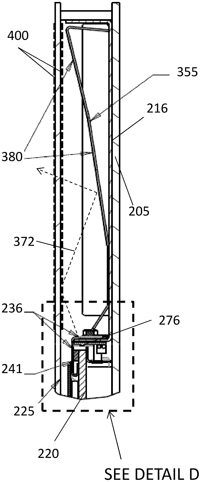
[0014] FIG. 7 is a detailed section view of Detail A shown in FIG. 5.
[0015] FIG. 8 is a detailed section view of Detail D shown in FIG. 7.
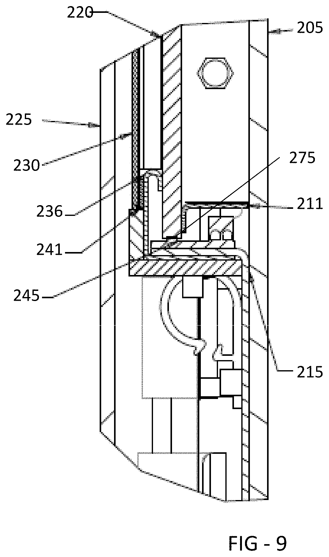
[0016] FIG. 9 is a detailed section view of Detail B shown in FIG. 5.
[0017] FIG. 10 is a perspective view of an exemplary embodiment of a front bracket when using the optional light bleeding technique.
[0018] FIG. 11 is a detailed section view of Detail C shown in FIG. 6.
[0019] FIG. 12 is a perspective view of a partially assembled exemplary embodiment of a sealed transparent LCD assembly.
DETAILED DESCRIPTION
[0020] The invention is described more fully hereinafter with reference to the accompanying drawings, in which exemplary embodiments of the invention are shown. This invention may, however, be embodied in many different forms and should not be construed as limited to the exemplary embodiments set forth herein. Rather, these embodiments are provided so that this disclosure will be thorough and complete, and will fully convey the scope of the invention to those skilled in the art. In the drawings, the size and relative sizes of layers and regions may be exaggerated for clarity.
[0021] The terminology used herein is for the purpose of describing particular embodiments only and is not intended to be limiting of the invention. As used herein, the singular forms "a", "an" and "the" are intended to include the plural forms as well, unless the context clearly indicates otherwise. It will be further understood that the terms "comprises" and/or "comprising," when used in this specification, specify the presence of stated features, integers, steps, operations, elements, and/or components, but do not preclude the presence or addition of one or more other features, integers, steps, operations, elements, components, and/or groups thereof.
[0022] Embodiments of the invention are described herein with reference to illustrations that are schematic illustrations of idealized embodiments (and intermediate structures) of the invention. As such, variations from the shapes of the illustrations as a result, for example, of manufacturing techniques and/or tolerances, are to be expected. Thus, embodiments of the invention should not be construed as limited to the particular shapes of regions illustrated herein but are to include deviations in shapes that result, for example, from manufacturing.
[0023] Unless otherwise defined, all terms (including technical and scientific terms) used herein have the same meaning as commonly understood by one of ordinary skill in the art to which this invention belongs. It will be further understood that terms, such as those defined in commonly used dictionaries, should be interpreted as having a meaning that is consistent with their meaning in the context of the relevant art and will not be interpreted in an idealized or overly formal sense unless expressly so defined herein.
[0024] FIG. 1 is a perspective view of a refrigerated display case having an exemplary sealed transparent LCD assembly 200. Generally, the display case includes a housing 105, to which a door frame assembly 100 is fastened. In this embodiment, a cavity 110 is provided below the door frame assembly 100 where various electronic devices 111 for operating the transparent LCD assembly 200 can be located. The electrical devices 111 may include any or all of the following: timing and control board (TCON), video player, hard drive/storage, microprocessor/CPU, wireless transmitter/receiver, cellular data transmitter/receiver, and internet connectivity. At least some of the electrical devices 111 are in electrical communication with the transparent LCD 200.
[0025] FIG. 2 is a perspective view of the refrigerated display case of FIG. 1 where the door has been opened.
[0026] FIG. 3 is a perspective view of the sealed transparent LCD assembly 200 of FIGS. 1-2. Generally speaking, the assembly includes a spacer 300 which is sandwiched between a front glass 225 and rear glass 205. These components are preferably sealed together with an inert gas filling the sealed enclosure. Although not required for every embodiment, argon gas has been found to be preferred in the exemplary embodiments. For sealing these components together, it is preferable to use a hot melt polyurethane. Preferably, the spacer 300 is the Super Spacer.RTM. Standard from Quanex in Cambridge, Ohio. www.quanex.com. In an exemplary embodiment, the spacer 300 would be a flexible foam that contains a desiccant and has a pressure sensitive acrylic adhesive on the front and back edges of the spacer which would be used to bond with the front and rear glass.
[0027] FIG. 4 is a front planar view of the sealed transparent LCD assembly 200, showing the section lines A-A and B-B. FIG. 5 is a section view taken along the section line A-A shown in FIG. 4 and indicating Detail A and Detail B. FIG. 6 is a section view taken along the section line B-B shown in FIG. 4 and indicating Detail C.
[0028] FIG. 7 is a detailed section view of Detail A shown in FIG. 5 while FIG. 8 is a detailed view of Detail D shown in FIG. 7. A top thermal plate 216 is preferably bonded to the rear glass 205. In an exemplary embodiment, the top thermal plate 216 is preferably bonded to the rear glass 205 through adhesive transfer tape. An exemplary adhesive transfer tape for this purpose would be 468 MP, available commercially from 3M.TM. of St. Paul, Minn. www.3M.com/converter. A printed circuit board (PCB) 246 containing a plurality of LEDs 276 is preferably attached to the top thermal plate 216 and is preferably in conductive thermal communication with the top thermal plate 216 as well. In this way, heat that is generated by the LEDs 276 can be transmitted to the PCB 246, top thermal plate 216, and eventually transferring to the rear glass 205 where the heat can dissipate through natural or forced convection.
[0029] The LEDs 276 are placed adjacent to the edge of a light guide 220 which is sandwiched between a rear bracket 211 and a front bracket 236. Generally speaking, the light guide 220 is only constrained from movement towards the front or back of the assembly, but is not constrained from movement towards the top or sides of the assembly. In other words, the light guide 220 should be secured such that it is capable of thermal expansion/contraction in the X-Y direction (horizontal and vertical when observing the LCD), but is fixed in the Z direction (into/out of the assembly when observing the LCD). It could also be said that the light guide 220 is preferably constrained so that it cannot move towards the front or rear glass but otherwise is permitted to float between the rear bracket 211 and front bracket 236. In an exemplary embodiment, the light guide 220 would be the Acrylite.RTM. LED Endlighten product available from Evonik Industries. www.acrylite-shop.com.
[0030] Preferably, the light guide 220 would contain microscopic diffuse particulate that is homogeneously scattered throughout the sheet. Also preferably, the light emitted from the LEDs 276 and 275 is permitted to exit both the front and rear surfaces of the light guide 220 (in this way, the light guide 220 could be referred to as a `two way light guide`). In an exemplary embodiment, the light is permitted to exit the rear of the light guide 220 so as to illuminate the products within the display case. Thus, it is preferable that the amount of light permitted to exit the rear surface of the light guide 220 is at least 20% of the amount of light permitted to exit the front surface of the light guide 220.
[0031] The transparent LCD 230 is preferably attached to a front surface of the front bracket 236 through a layer of adhesive 241 which would preferably be applied around the perimeter of the LCD 230. In an exemplary embodiment, the adhesive 241 would be VHB tape and preferably 5052 VHB Tape available commercially from 3M.TM. of St. Paul, Minn. www.3M.com.
[0032] In an exemplary embodiment, the front bracket 236 may contain a plurality of apertures 351 (see FIG. 10) which permit light 372 from the LEDs 276 to pass through the front bracket 236 and enter the area above the front bracket 236. In this way, some light from the LED 276 is permitted to enter a top cavity of the sealed transparent LCD assembly. The cavity may be defined by the space between a rear wall 355 and the front glass 225. The light 372 is permitted to reflect off the rear wall 355 and exit through the front glass 225. In some embodiments, a static graphic 400 may be placed on the front glass 225 (either the front surface or the rear surface) such that the light 372 which eventually exits out of the front glass 225 can illuminate the graphic 400. Thus, the apertures 351 which are contained within the front bracket 236 may allow the light 372 from the LED 276 to bleed off the main light guide 220 and be used to backlight the graphic 400. Preferably, the front surfaces 380 of the rear wall 355 are reflective.
[0033] A dark colored mask 405 may be applied to the front glass 225 to ensure that the light 372 from the LED 276 is not directly visible to an observer. The dark colored mask 405 is preferably black and may be bonded to either the interior or exterior surface of the front glass 225. Preferably, the mask 405 is placed along the line of sight of an intended observer who observes the LED 276, where the mask 405 is positioned between the intended observer and the LED 276.
[0034] FIG. 9 is a detailed section view of Detail B shown in FIG. 5. A bottom thermal plate 215 is preferably bonded to the rear glass 205. In an exemplary embodiment, the bottom thermal plate 215 is preferably bonded to the rear glass 205 through adhesive transfer tape. An exemplary adhesive transfer tape for this purpose would be 468 MP, available commercially from 3M.TM. of St. Paul, Minn. www.3M.com/converter. A printed circuit board (PCB) 245 containing a plurality of LEDs 275 is preferably attached to the bottom thermal plate 215 and is preferably in conductive thermal communication with the bottom thermal plate 215 as well. In this way, heat that is generated by the LEDs 275 can be transmitted to the PCB 245, bottom thermal plate 215, and eventually transferring to the rear glass 205 where the heat can dissipate through natural or forced convection.
[0035] The LEDs 275 are placed adjacent to the edge of a light guide 220 which is sandwiched between a rear bracket 211 and a front bracket 236. As discussed at length above, the light guide 220 is preferably only constrained from movement towards the front or back of the assembly, but is not contained from movement towards the top or sides of the assembly. It should be noted that the front bracket 236 could also contain the apertures 351 so that light from the LED 275 may bleed into the cavity below front bracket 236, in order to illuminate a graphic that could be placed on the front glass 225 below the front bracket 236. While not shown here, static graphics could also be placed below the front bracket 236 with a rear wall 355 similar to what is shown and described above with reference to FIG. 7.
[0036] FIG. 11 is a detailed section view of Detail C shown in FIG. 6.
[0037] FIG. 12 is a perspective view of a partially assembled exemplary embodiment of a sealed transparent LCD assembly. This view shows the rear glass 205 with the spacer 300 attached around the perimeter of the glass 205. Also shown is the rear bracket 211 which is attached to the rear glass 205 as well.
[0038] The embodiments of the sealed transparent LCD assembly described herein can be used with any number of display case designs, either temperature controlled or not, and with doors that open or glass that remains stationary.
[0039] Having shown and described a preferred embodiment of the invention, those skilled in the art will realize that many variations and modifications may be made to affect the described invention and still be within the scope of the claimed invention. Additionally, many of the elements indicated above may be altered or replaced by different elements which will provide the same result and fall within the spirit of the claimed invention. It is the intention, therefore, to limit the invention only as indicated by the scope of the claims.
* * * * *
References
D00000
D00001
D00002
D00003
D00004
D00005
D00006
D00007
XML
uspto.report is an independent third-party trademark research tool that is not affiliated, endorsed, or sponsored by the United States Patent and Trademark Office (USPTO) or any other governmental organization. The information provided by uspto.report is based on publicly available data at the time of writing and is intended for informational purposes only.
While we strive to provide accurate and up-to-date information, we do not guarantee the accuracy, completeness, reliability, or suitability of the information displayed on this site. The use of this site is at your own risk. Any reliance you place on such information is therefore strictly at your own risk.
All official trademark data, including owner information, should be verified by visiting the official USPTO website at www.uspto.gov. This site is not intended to replace professional legal advice and should not be used as a substitute for consulting with a legal professional who is knowledgeable about trademark law.