Semi-automatic Or Fully Automatic Firearm
KIRSTEIN; Gerhard
U.S. patent application number 16/747053 was filed with the patent office on 2020-07-23 for semi-automatic or fully automatic firearm. The applicant listed for this patent is Gerhard KIRSTEIN. Invention is credited to Gerhard KIRSTEIN.
| Application Number | 20200232739 16/747053 |
| Document ID | / |
| Family ID | 71402489 |
| Filed Date | 2020-07-23 |

| United States Patent Application | 20200232739 |
| Kind Code | A1 |
| KIRSTEIN; Gerhard | July 23, 2020 |
SEMI-AUTOMATIC OR FULLY AUTOMATIC FIREARM
Abstract
A semi-automatic or fully automatic firearm (2) having a barrel (4), the rear end of which is in the form of a cartridge chamber (8), in which each round can be inserted from the rear; a breech body (6) that is movable in a longitudinal direction of the barrel between an open position for releasing the cartridge chamber (8) for reloading a round and a locking position that locks the cartridge chamber (8), wherein in the locking position the breech body (6) closes the cartridge chamber (8) at the rear and the cartridge casing acts as a thrust bearing, wherein the firearm (2) has a breech body locking device (20) that is designed to move a breech body lock from a breech body release position for releasing the breech body (6) to a breech body locking position for locking the breech body (6) and from the breech body locking position to the breech body release position, wherein the breech body locking device (20) has an electromagnet (24) for moving the breech body lock from the breech body release position to the breech body locking position, and/or an electromagnet (24) for moving the breech body lock from the breech body locking position to the breech body release position, as well as a firearm (2) with an electromagnetically driven firing pin (18).
| Inventors: | KIRSTEIN; Gerhard; (Augsburg, DE) | ||||||||||
| Applicant: |
|
||||||||||
|---|---|---|---|---|---|---|---|---|---|---|---|
| Family ID: | 71402489 | ||||||||||
| Appl. No.: | 16/747053 | ||||||||||
| Filed: | January 20, 2020 |
| Current U.S. Class: | 1/1 |
| Current CPC Class: | F41A 3/68 20130101; F41A 19/13 20130101; F41A 19/27 20130101; F41A 3/10 20130101 |
| International Class: | F41A 19/27 20060101 F41A019/27; F41A 3/68 20060101 F41A003/68; F41A 3/10 20060101 F41A003/10 |
Foreign Application Data
| Date | Code | Application Number |
|---|---|---|
| Jan 18, 2019 | DE | 10 2019 000 301.2 |
Claims
1. A semi-automatic or fully automatic firearm having a barrel, the rear end of which is designed as a cartridge chamber, into which a round can be inserted from the rear, respectively; a breech body, which is movable in a longitudinal direction of the barrel between an open position for releasing the cartridge chamber for the reloading of a round and a closing position that closes the cartridge chamber, wherein in the closing position the breech body closes the cartridge chamber to the rear and acts as a thrust bearing for a cartridge casing, wherein the firearm has a breech locking device that is designed to move a breech body lock from a breech body release position for releasing the breech body to a breech body locking position for locking the breech body in its closing position and from the breech body locking position to the breech body release position, wherein the breech locking device has an electromagnet for moving the breech body lock from the breech body release position to the breech body locking position, or has an electromagnet for moving the breech body lock from the breech body locking position to the breech body release position, or has an electromagnet for moving the breech body lock from the breach body release position to the breech body locking position and for moving the breech body lock from the breech body locking position to the breech body release position.
2. The firearm as claimed in claim 1, wherein the breech locking device has an elastic element, in particular a spring, further in particular a coil compression spring or a coil pull-back spring.
3. The firearm as claimed in claim 1, wherein when the electromagnet is in a deenergized state, the breech body lock is arranged in the breech body release position.
4. The firearm as claimed in claim 1, wherein when the electromagnet is in an energized state, the breech body lock is in the breech body release position.
5. The firearm as claimed in claim 1, wherein the firearm also has a firing pin and the breech body lock has a locking section, wherein the locking section has a recess in which the firing pin is arranged to be movable reciprocally in the longitudinal direction of the barrel.
6. The firearm, in particular a firearm as claimed in claim 1, wherein the firearm has a firing device that has at least one electromagnet for at least partial actuation of same.
7. The firearm as claimed in claim 6, wherein the firing device has a firing pin that is movable from a neutral position to a firing position by means of the electromagnet.
8. The firearm as claimed in claim 6, wherein the firing pin or a section thereof is movable from the firing position to the neutral position by means of the electromagnet.
9. The firearm as claimed in claim 6, wherein the firing device has more than one electromagnet, in particular 3 electromagnets.
10. The firearm as claimed in claim 7, wherein the firing pin is of a multi-part form, in particular of a two-piece form.
11. The firearm as claimed in claim 7, wherein the firing device has an elastic element, in particular a spring.
Description
[0001] The invention relates to a semi-automatic or fully automatic firearm as claimed in the preamble of claim 1.
[0002] Firearms with a locked breech and firearms with an unlocked breech are known from the prior art. In the area of firearms with locked breeches, various locking systems are known, for example combs on a barrel of the weapon and corresponding grooves in a carriage of the weapon or even a breech block on the end of the barrel, locking in the ejection port of the carriage. Other components of the firearms as claimed in the state of the art also have a somewhat complicated mechanical construction, which is expensive and prone to malfunctions.
[0003] Based on the prior art explained above, it is the object of the present invention to specify a firearm that allows a simple and cost-effective construction.
[0004] The object of the invention is achieved with regard to its apparatus aspect by a firearm with the features of claim 1.
[0005] The object of the present invention is thus achieved by a semi-automatic or fully automatic firearm, which has the following: a barrel, the rear end of which is embodied as a cartridge chamber, in which a round can be inserted from the rear, a breech body that is movable in the longitudinal direction of the barrel between an open position for releasing the cartridge chamber for the reloading of a round and a closing position for closing the cartridge chamber, wherein in the closing position the breech body closes the cartridge chamber to the rear and acts as a thrust bearing for the cartridge sleeve. The firearm comprises a breech locking device, which is designed to move a breech body lock from a breech body release position for releasing the breech body into a breech body locking position for locking the breech body in its closing position and from the breech body locking position to the breech body release position. The breech locking device comprises an electromagnet for moving the breech body lock from the breech body release position to the breech body locking position, or comprises an electromagnet for moving the breech body lock from the breech body locking position to the breech body release position, or has an electromagnet for moving the breech body lock from the breech body locking position to the breech body release position and for moving the breech body lock from the breech body release position to the breech body locking position.
[0006] This means that the breech locking device has an electromagnet that may be designed to move the breech body lock by generating a magnetic field and a resulting force acting on the breech body lock to the breech body locking position in which the breech body is locked by the lock. In addition or alternatively, for this purpose the electromagnet is designed to move the breech body lock by generating a magnetic field and a resulting force that acts on the breech body lock to move it to the breech body release position in which the breech body is released. This ensures effective actuation of the breech body lock or of a breech body locking element at the same time as a simple design.
[0007] As a solution to the object underlying the invention, reference should also be made to a firearm having a firing device having at least one electromagnet for at least partial actuation of the same. In particular, the firing device may have a firing pin that is moved by means of the electromagnet from a neutral position to a firing position. As an alternative to this or even additionally, the firing pin may be moved from the firing position to the neutral position by means of the electromagnet.
[0008] It should be noted at this point that the firearm with the firing device described above does not have to be a locked weapon, but may also be any other firearm.
[0009] Further features of the invention are contained in the subordinate claims.
[0010] The invention is described below with reference to the enclosed drawings on the basis of possible embodiments as examples. In the figures:
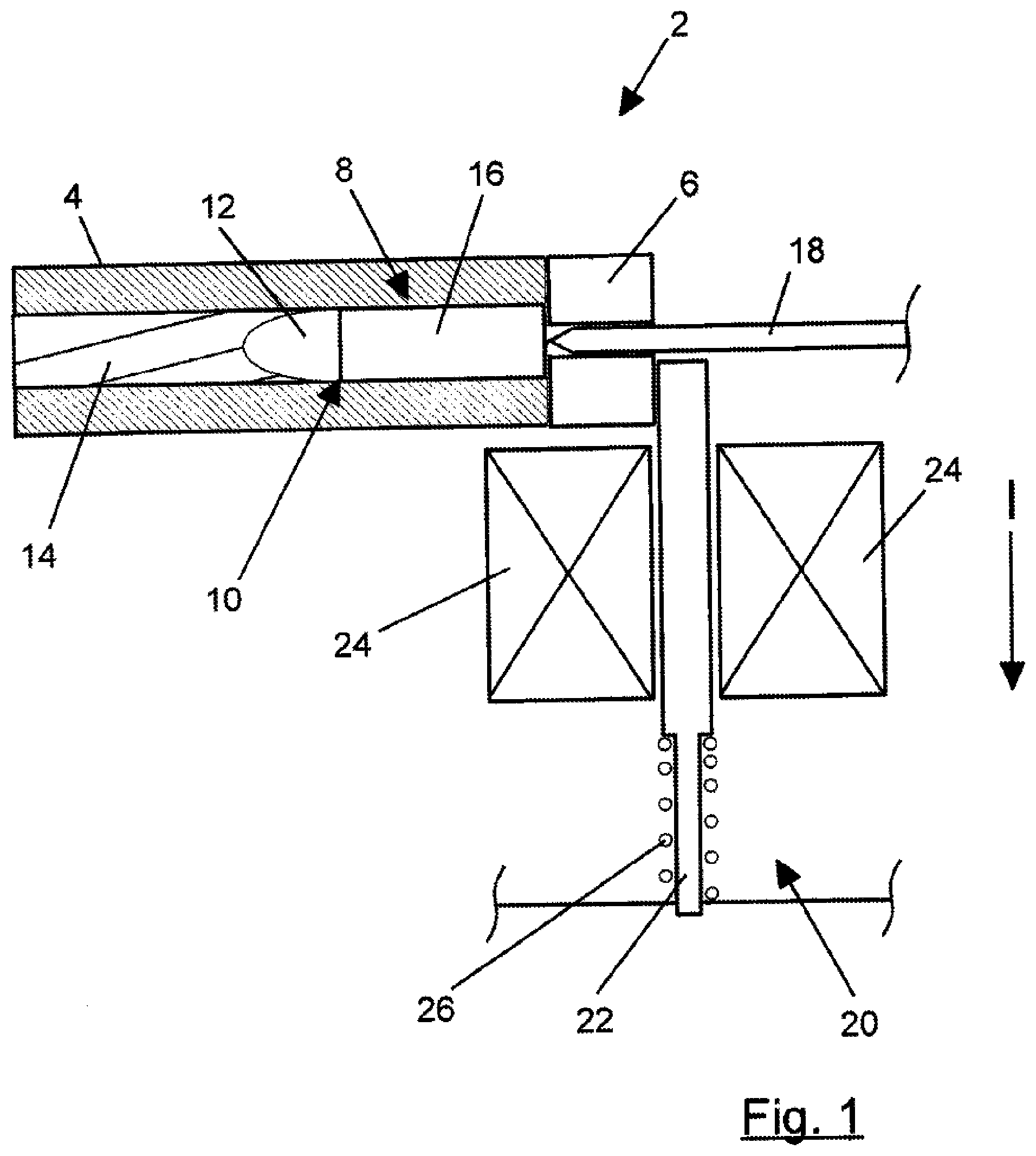
[0011] FIG. 1 shows a partial view (sectional view) of a first possible embodiment of a firearm according to the invention in a breech body locking position;
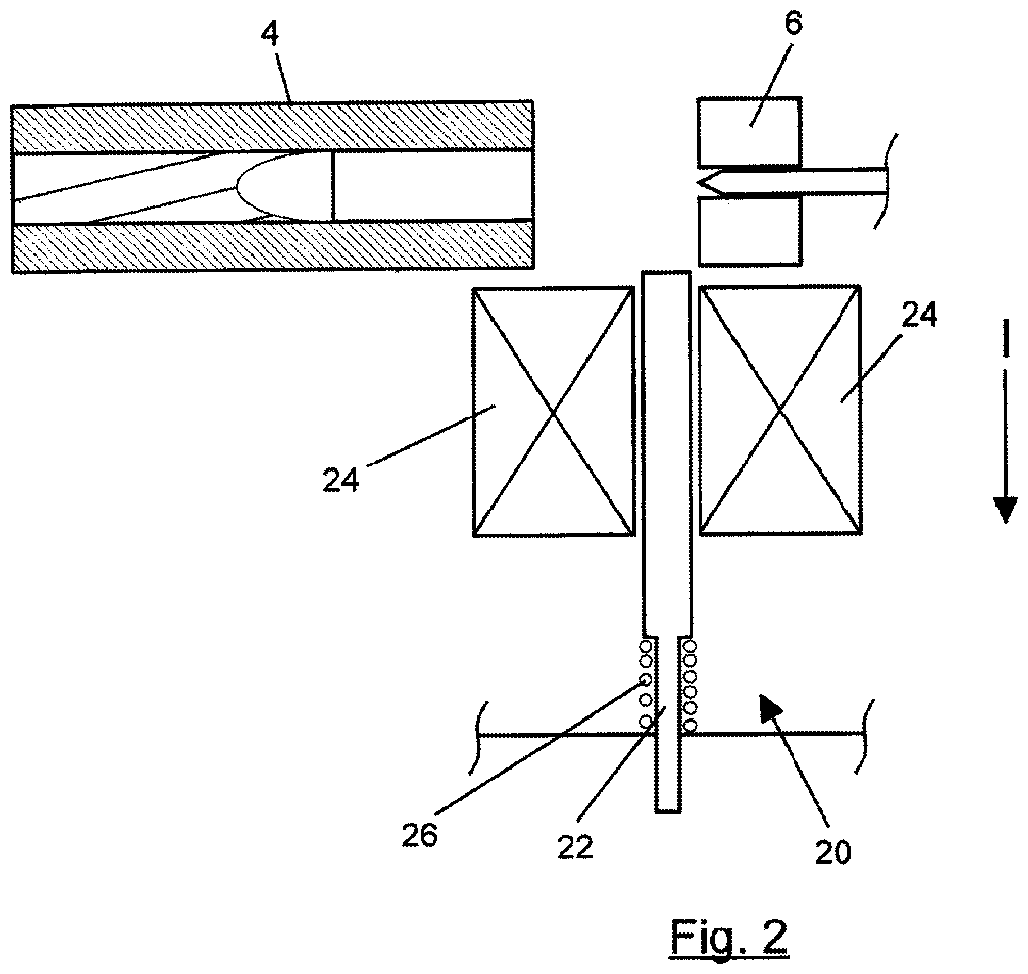
[0012] FIG. 2 shows a partial view (sectional view) of a first possible embodiment of a firearm according to the invention in a breech body release position;
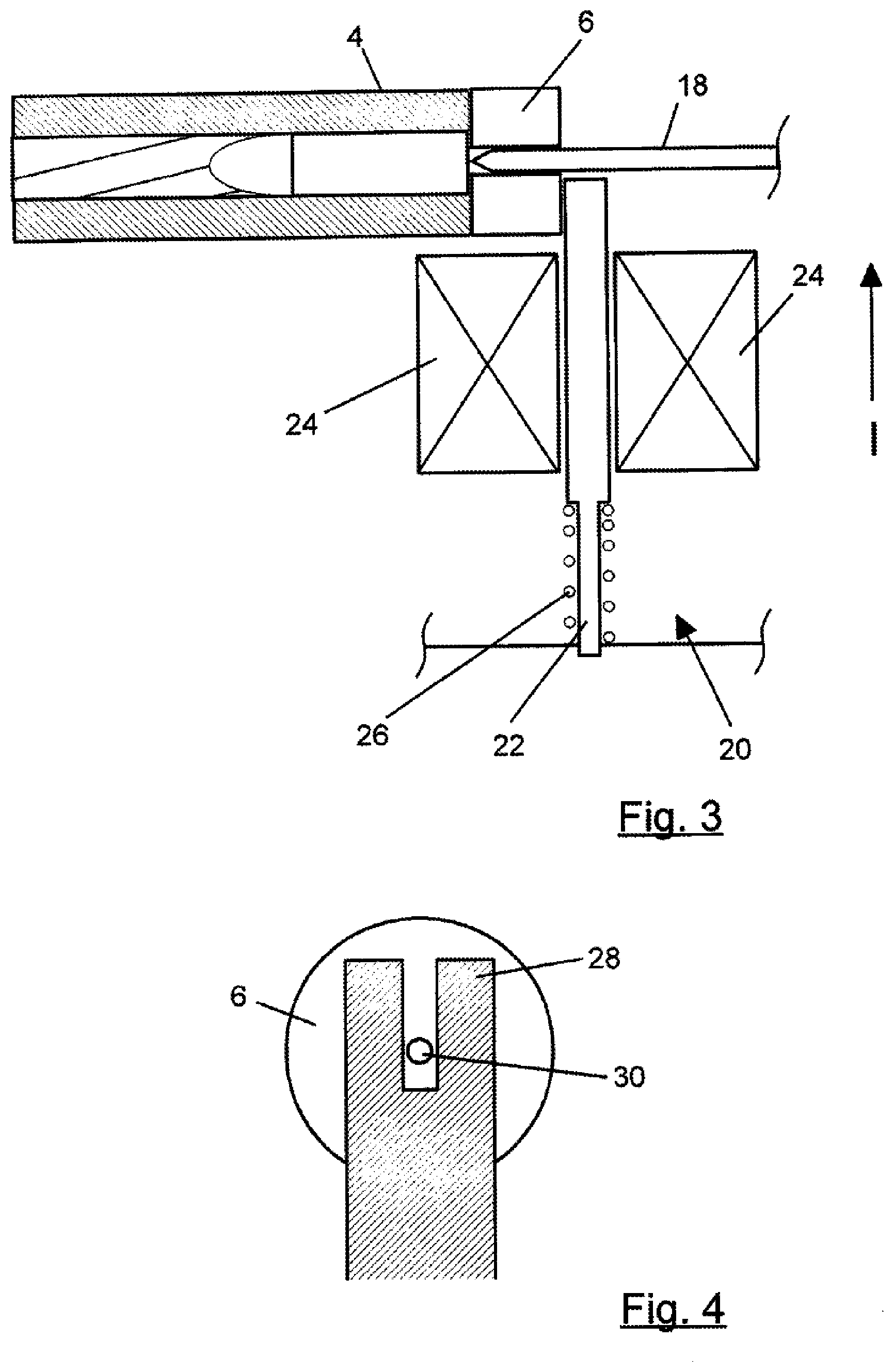
[0013] FIG. 3 shows a partial view (sectional view) of a second possible embodiment of a firearm according to the invention in a breech body locking position;
[0014] FIG. 4 shows a further partial view (sectional view) of an embodiment of a firearm according to the invention, the constructive details of which are realized in both the first and the second embodiments;
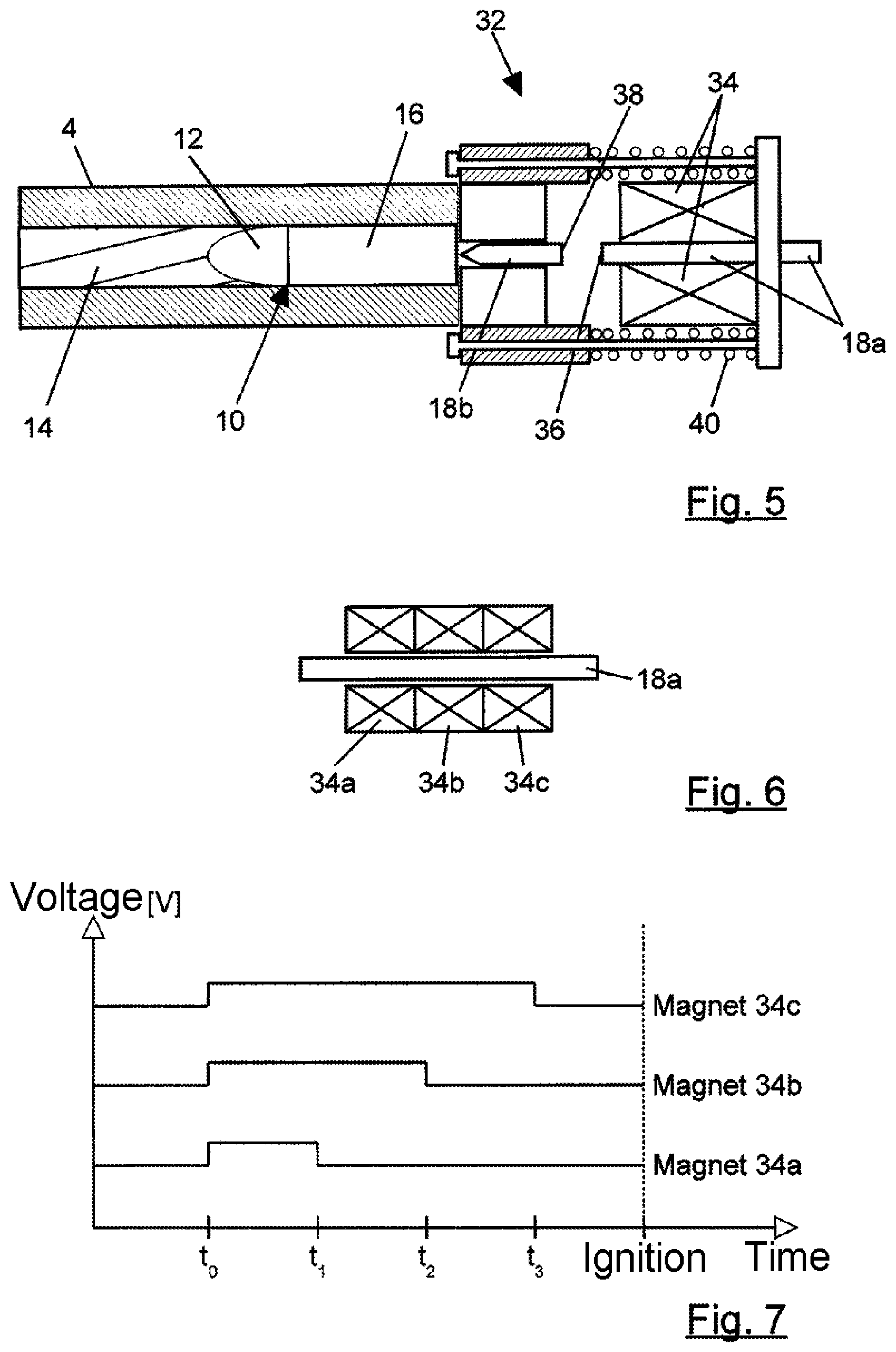
[0015] FIG. 5 shows a sectional view of a part of another possible embodiment of a firearm, which constitutes a firing device of the firearm;
[0016] FIG. 6 shows a schematic view of an alternative embodiment to the embodiment of FIG. 5 of a firearm with a firing device with three electromagnets;
[0017] FIG. 7 shows a diagram showing a duty cycle of the electromagnets of the embodiment shown in FIG. 6.
[0018] FIG. 1, FIG. 2 and FIG. 3 show a barrel 4 and a breech body 6 of a firearm 2 according to the invention. A rear section of the barrel 4 is designed as a cartridge chamber 8. The breech body 6 can be moved in a breech guide (not shown) in the longitudinal direction of the barrel 4 between the breech body locking position shown in FIG. 1 and the breech body release position shown in FIG. 2.
[0019] In the closing position shown in FIG. 1, the breech body 6 forms a thrust bearing for absorbing the recoil on the ignition of the (not shown) propellant charge of the cartridge 10. On the ignition of the propellant charge of the cartridge 10, the bullet 12 is driven through a bore 14 of the barrel 4, while a cartridge casing 16 is held in the cartridge chamber 8 by the breech body 6 against the pressure of the explosion of the propellant charge.
[0020] After firing, the breech body 6 is moved back to the open position shown in FIG. 2. The cartridge casing 16 is ejected during this, so that a new cartridge can then be automatically inserted into the cartridge chamber 8.
[0021] To ignite the propellant charge of the cartridge 10, a firing pin 18 strikes the center on the rear of the cartridge 10.
[0022] The firearm has a breech locking device 20 that is designed to move a breech body lock in the form of a locking bolt 22 from a breech body release position (in FIG. 2) for releasing the breech body 6 to a breech body locking position 6 (shown in FIG. 1 and FIG. 3) for locking the breech body in the closing position and from the breech body locking position to the breech body release position.
[0023] For this purpose, the breech locking device 20 in the embodiments described in FIG. 1 to FIG. 3 comprises an electromagnet 24 and an elastic element in the form of a spring 26, which has a working engagement with the locking bolt or engages the bolt in a force-locking manner or is connected to the bolt in a force-locking manner. The electromagnet is arranged in such a way that a magnetic field generated thereby acts on the locking bolt 22. In the embodiments described, a section of the locking bolt 22 is arranged within the electromagnet (somewhat like a coil core, but movable with respect to the magnet).
[0024] With the embodiment shown in FIG. 1 and FIG. 2, the spring 26 is formed as a coil compression spring that pushes the locking bolt 22 into the breech body locking position by means of the spring force thereof. If a position of the locking bolt 22 in the breech body locking position is desired, the electromagnet 24 is left in or set into a deenergized state and the spring force presses the locking bolt 22 into the breech body locking position.
[0025] If movement of the locking bolt 22 into the breech body release position is desired, the electromagnet 24 is energized, so that the locking bolt 22 is pulled into the breech body release position by the force acting thereon due to the resulting magnetic field and the breech body 6 is thus released.
[0026] With the embodiment shown in FIG. 3, the spring 26 is in the form of a coil pullback spring, which pulls the locking bolt 22 into the breech body release position by means of the spring force thereof. If a position of the locking bolt 22 in the breech body release position is desired, the electromagnet 24 is left in or set into a deenergized state and the spring force pulls the locking bolt 22 into the breech body release position.
[0027] If movement of the locking bolt 22 into the breech body locking position is desired, the electromagnet 24 is energized, so that the locking bolt 22 is pulled into the breech body locking position by the force acting on it due to the resulting magnetic field and thus locks the breech body 6.
[0028] The locking bolt 22 has, besides the section that is arranged in the electromagnet 24, a locking section 28 that has a recess in which the firing pin 18 is arranged to move reciprocally in the longitudinal direction of the barrel. In the embodiment described in FIG. 4, the locking section is of an approximately U-shaped form in a plan view from behind of the breech body 6 of the firearm 2. This ensures that the firing pin 18 can hit the center on the rear of the cartridge 10 unhindered to ignite the propellant charge of the cartridge 10. This is shown in FIG. 4, from which it is also apparent that the breech body 6 has a cylindrical recess in the form of a bore 30, through which the firing pin 18 can pass and can ignite the propellant charge. Alternatively to this, the locking section may, for example, also comprise a bore or a different type of recess, in particular a bore corresponding to the bore 30 arranged in the breech body 6.
[0029] In an alternative embodiment, the spring 26 can be omitted. In this case, the electromagnet is used both for movement of the locking bolt 22 into the breech body locking position as well as for movement of the locking bolt 22 into the breech body release position. For this purpose, it is conceivable, for example, that the locking bolt has magnetic portions, which depending on the magnetic field direction are used for movement of the locking bolt 22 in the desired direction during an interaction with the magnetic field. In this case, the magnetic field direction can be reversed, for example, by a reversal of the current, which reverses the magnetic field of the electromagnet 24, which leads to opposite movements of the locking bolt 22. Alternatively, for example, the use of multiple electromagnets is conceivable, of which each electromagnet is provided for a movement of the locking bolt 22 in a different direction.
[0030] The firearm also comprises a firing device 32 that comprises another electromagnet 34 for at least partial actuation thereof in an embodiment described in FIG. 5 and FIG. 6. The firing device 32 further comprises the firing pin 18, which is of a two-piece form in the embodiment described in FIG. 5 and FIG. 6 and has a first firing pin section 18a and a second firing pin section 18b. Alternatively to this, the firing pin can also be in a one-piece form or a three-piece form or a multi-part form.
[0031] The first firing pin section 18a is arranged within the electromagnet 34 so as to be movable reciprocally in a longitudinal direction (again like a coil core, but movable) and is subjected to force by the field generated by the electromagnet due to its arrangement and can thus be moved by the action of the magnetic field. The second firing pin section 18b is arranged or supported in the breech body 6 so as to be movable reciprocally in the longitudinal direction.
[0032] The first firing pin section 18a can be moved by means of the force generated by the electromagnet 34 (when the electromagnet 34 is energized) from a neutral position (shown in FIG. 5) to a firing position, in which the first firing pin section 18a with an end face 36 facing towards the second firing pin section 18b meets an end face 38 of the second firing pin section 18b facing towards the first firing pin section 18a and, due to the kinetic energy thereof that is transmitted to the second firing pin section 18b, knocks the second firing pin section 18b towards the cartridge, which results in the ignition of the propellant charge.
[0033] The firing device 32 also comprises an elastic element in the form of a spring 40, which is in the form of a coil compression spring in the embodiment shown in FIG. 5 and which has a working engagement with or is connected in a force-locking manner to the first firing pin section 18a such that the spring force pushes the first firing pin section 18a into the neutral position.
[0034] In an alternative embodiment to this, the firing pin 18 (this in turn can be embodied in one piece or multiple pieces) can be moved by means of the electromagnet not only from the neutral position to a firing position but also from the firing position to the neutral position. For this purpose, in the embodiment shown in FIG. 6 there are three electromagnets 34a, 34b and 34c. The first firing pin section 18a (alternatively a section of the firing pin 18 in the case of a one-piece implementation of the firing pin) is arranged within the electromagnets 34a, 34b and 34c. By means of a time-varying energization of the individual electromagnets 34a, 34b and 34c, a movement of the first firing pin section 18a can be achieved either towards the neutral position or towards the firing position. By the time-varying energization, an acceleration in the desired direction of motion can also be achieved, for example an energization profile against time as shown in FIG. 7 is realized.
[0035] From the moment at which the firing is initiated (t0), all three electromagnets 34a, 34b and 34c are energized. At time t1, the first electromagnet 34a is switched to deenergized, from the time t2 the second electromagnet 34b is switched to deenergized and the third electromagnet 34c is switched to deenergized last at time t3. Here t1<t2<<t3 applies. The first electromagnet 34a is located furthest away from the cartridge 10 and the third electromagnet 34c is located closest to the cartridge 10, while the second electromagnet 34b is arranged in the middle between the other two. By this energization scheme, an acceleration of the first firing pin section 18a towards the firing position is achieved. Similarly, an acceleration in the other direction can also be produced by a correspondingly modified energization scheme.
[0036] Although the invention is described on the basis of embodiments with fixed combinations of features, it does however also include conceivable further advantageous combinations of features, as they are in particular but not exhaustively indicated by the subordinate claims. All disclosed features indicated in the filing documents are claimed as essential to the invention, insofar as they are new individually or in combination compared to the prior art.
* * * * *
D00000
D00001
D00002
D00003
D00004
XML
uspto.report is an independent third-party trademark research tool that is not affiliated, endorsed, or sponsored by the United States Patent and Trademark Office (USPTO) or any other governmental organization. The information provided by uspto.report is based on publicly available data at the time of writing and is intended for informational purposes only.
While we strive to provide accurate and up-to-date information, we do not guarantee the accuracy, completeness, reliability, or suitability of the information displayed on this site. The use of this site is at your own risk. Any reliance you place on such information is therefore strictly at your own risk.
All official trademark data, including owner information, should be verified by visiting the official USPTO website at www.uspto.gov. This site is not intended to replace professional legal advice and should not be used as a substitute for consulting with a legal professional who is knowledgeable about trademark law.