Heat Exchanger
SUGIMURA; Ryohei ; et al.
U.S. patent application number 16/841260 was filed with the patent office on 2020-07-23 for heat exchanger. The applicant listed for this patent is DENSO CORPORATION. Invention is credited to Tetsuya ITO, Daiki KATO, Masaaki KAWAKUBO, Hiroshi MIEDA, Ryohei SUGIMURA.
| Application Number | 20200232726 16/841260 |
| Document ID | / |
| Family ID | 66100861 |
| Filed Date | 2020-07-23 |


| United States Patent Application | 20200232726 |
| Kind Code | A1 |
| SUGIMURA; Ryohei ; et al. | July 23, 2020 |
HEAT EXCHANGER
Abstract
A heat exchanger has an inflow port through which refrigerant flows, a cooling outflow port through which the refrigerant flows out during a cooling operation, and a heating outflow port through which the refrigerant flows out during a heating operation. A distance between the inflow port and the heating outflow port is shorter than a distance between the inflow port and the cooling outflow port.
| Inventors: | SUGIMURA; Ryohei; (Kariya-city, JP) ; KAWAKUBO; Masaaki; (Kariya-city, JP) ; KATO; Daiki; (Kariya-city, JP) ; ITO; Tetsuya; (Kariya-city, JP) ; MIEDA; Hiroshi; (Kariya-city, JP) | ||||||||||
| Applicant: |
|
||||||||||
|---|---|---|---|---|---|---|---|---|---|---|---|
| Family ID: | 66100861 | ||||||||||
| Appl. No.: | 16/841260 | ||||||||||
| Filed: | April 6, 2020 |
Related U.S. Patent Documents
| Application Number | Filing Date | Patent Number | ||
|---|---|---|---|---|
| PCT/JP2018/037044 | Oct 3, 2018 | |||
| 16841260 | ||||
| Current U.S. Class: | 1/1 |
| Current CPC Class: | F25B 41/003 20130101; F25B 39/02 20130101; F25B 6/04 20130101; F25B 39/04 20130101; F25B 41/04 20130101; F25B 39/00 20130101; F25B 29/003 20130101; F28F 13/06 20130101; F25B 5/04 20130101; B60H 1/32 20130101 |
| International Class: | F28F 13/06 20060101 F28F013/06; F25B 29/00 20060101 F25B029/00; F25B 41/00 20060101 F25B041/00; F25B 41/04 20060101 F25B041/04 |
Foreign Application Data
| Date | Code | Application Number |
|---|---|---|
| Oct 11, 2017 | JP | 2017-197822 |
Claims
1. A heat exchanger for a heat pump system that performs a cooling operation and a heating operation, the heat exchanger comprising: a heat exchanging portion configured to perform heat exchange between a refrigerant and an outside air during the cooling operation and the heating operation; a refrigerant adjustment unit that is integrally joined with a liquid reservoir that stores liquid refrigerant, and that switches a flow of the refrigerant during the cooling operation and the heating operation; an inflow port into which the refrigerant flows; a cooling outflow port through which the refrigerant flows out during the cooling operation; and a heating outflow port through which the refrigerant flows out during the heating operation, wherein a distance between the inflow port and the heating outflow port is shorter than a distance between the inflow port and the cooling outflow port.
2. The heat exchanger according to claim 1, wherein a heat transfer member is provided between the inflow port and the heating outflow port.
3. The heat exchanger according to claim 2, wherein the inflow port, the heating outflow port, and the heat transfer member are configured by a single connector component.
4. The heat exchanger according to claim 3, wherein the connector component is connected so that a space between the inflow port and the heating outflow port is filled with the heat transfer member.
5. The heat exchanger according to claim 3, wherein the cooling outflow port is provided in a component different from the connector component.
6. The heat exchanger according to claim 1, wherein the inflow port and the heating outflow port are arranged such that a flow direction of the refrigerant at the inflow port is opposite to a flow direction of the refrigerant at the heating outflow port.
7. The heat exchanger according to claim 1, wherein the inflow port, the heating outflow port, and the cooling outflow port are arranged in this order in a longitudinal direction of the liquid reservoir.
Description
CROSS REFERENCE TO RELATED APPLICATIONS
[0001] This application is a continuation application of International Patent Application No. PCT/JP2018/037044 filed on Oct. 3, 2018, which designated the U.S. and based on and claims the benefits of priority of Japanese Patent Application No. 2017-197822 filed on Oct. 11, 2017. The entire disclosure of all of the above applications is incorporated herein by reference.
TECHNICAL FIELD
[0002] The present disclosure relates to a heat exchanger used in a heat pump system that performs a cooling operation and a heating operation.
BACKGROUND
[0003] A heat exchanger used in a heat pump system performs a cooling operation and a heating operation.
SUMMARY
[0004] An object of the present disclosure is to provide a heat exchanger that is capable of improving heating performance and cooling performance and suppressing generation of abnormal noise during the cooling operation.
[0005] A heat exchanger of the present embodiment is a heat exchanger used for a heat pump system that performs a cooling operation and a heating operation. The heat exchanger includes a heat exchanging portion that performs heat exchange between the refrigerant and the outside air during the cooling operation and the heating operation, and a refrigerant adjustment unit that is integrally joined to a liquid reservoir that stores liquid refrigerant, and that switches the flow of the refrigerant during the cooling operation and the heating operation. The heat exchanger has an inflow port through which the refrigerant flows, a cooling outflow port through which the refrigerant flows out during the cooling operation, and a heating outflow port through which the refrigerant flows out during the heating operation. A distance between the inflow port and the heating outflow port is shorter than a distance between the inflow port and the cooling outflow port.
BRIEF DESCRIPTION OF DRAWINGS
[0006] FIG. 1 is a diagram illustrating a heat exchanger according to one embodiment;
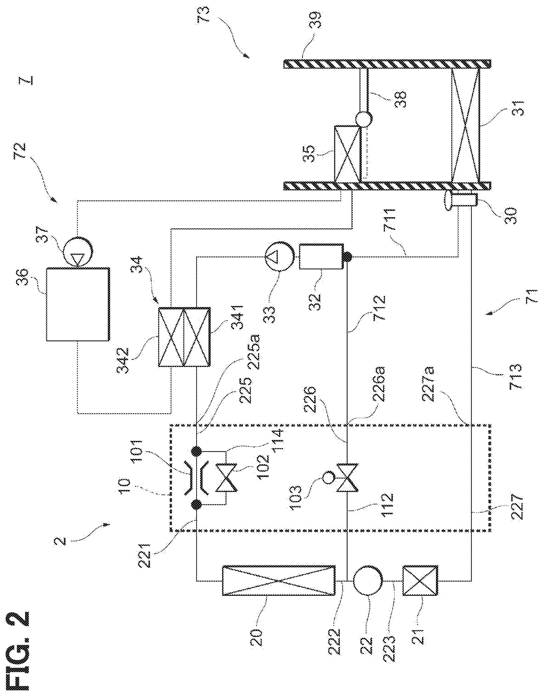
[0007] FIG. 2 is a diagram showing an example of a refrigeration cycle using the heat exchanger shown in FIG. 1;
[0008] FIG. 3 is a diagram showing a heat exchanger as a modification;
[0009] FIG. 4 is a diagram showing a heat exchanger as a modification;
[0010] FIG. 5 is a diagram showing a heat exchanger as a modification;
[0011] FIG. 6 is a diagram for explaining a connector component shown in FIG. 1;
[0012] FIG. 7 is a diagram for explaining the connector component shown in FIG. 1;
[0013] FIG. 8 is a diagram for explaining a connector component shown in FIG. 3; and
[0014] FIG. 9 is a diagram for explaining the connector component shown in FIG. 3.
DETAILED DESCRIPTION
[0015] Hereinafter, the present embodiments will be described with reference to the attached drawings. In order to facilitate the ease of understanding, the same reference numerals are attached to the same constituent elements in each drawing where possible, and redundant explanations are omitted.
[0016] As shown in FIG. 1, a heat exchanger 2 according to a present embodiment includes an upstream heat exchanging portion 20, a downstream heat exchanging portion 21, and a liquid reservoir 22. The upstream heat exchanging portion 20 has two upstream cores 201, 202 and header tanks 203, 204, 205. In the present embodiment, as the illustrated example, the upstream heat exchanging portion 20 has two upstream cores 201, 202, but a single core or three or more cores may be used. The upstream cores 201, 202 are parts that exchange heat between the refrigerant flowing therein and the air flowing outside, and includes tubes through which the refrigerant flows and fins provided between the tubes.
[0017] At the upstream end of the upstream core 201, the header tank 203 is attached. At the downstream end of the upstream core 202, the header tank 205 is attached. At the downstream end of the upstream core 201 and the upstream end of the upstream core 202, the header tank 204 extending across the both of the upstream cores 201, 202 is attached.
[0018] The connection channel 221 is connected to the header tank 203. The connection channel 222 is connected to the header tank 205. The refrigerant flowing in from the connection channel 221 flows into the upstream core 201 through the header tank 203. The refrigerant flowing through the upstream core 201 flows into the header tank 204. The refrigerant flowing through the header tank 204 flows into the upstream core 202. The refrigerant flowing through the upstream core 202 flows into the header tank 205. The refrigerant flowing into the header tank 205 flows out to the connection channel 222.
[0019] The connection channel 222 is a flow channel provided in the liquid reservoir 22. The connection channel 222 is connected to a liquid reserve space 224 of the liquid reservoir 22. The refrigerant flowing out to the connection channel 222 flows into a liquid reserve space 224.
[0020] The liquid reservoir 22 has a substantially cylindrical shape in which a liquid reserve space 224 is formed. The liquid reserve space 224 is a portion that separates the gas-liquid two-phase refrigerant flowing therein from the connection channel 222 into a liquid-phase refrigerant and a gas-phase refrigerant, and reserves the liquid-phase refrigerant. The liquid reservoir 22 includes an inflow channel 225, the connection channel 221, the connection channel 222, a heating outflow channel 226, and a connection channel 223. An inflow port 225a is formed at an end of the inflow channel 225. A heating outflow port 226a is formed at an end of the heating outflow channel 226.
[0021] The connection channel 222, the connection channel 223, and an outflow channel 112 are connected to the liquid reserve space 224. The connection channel 222 is a channel connecting the upstream heat exchanging portion 20 and the liquid reservoir 22. The connection channel 223 is a channel connecting the liquid reservoir 22 and the downstream heat exchanging portion 21. The liquid-phase refrigerant flowing out from the connection channel 223 flows into the downstream heat exchanging portion 21. The outflow channel 112 is a flow passage that allows gas-phase refrigerant to flow out from the liquid reservoir 22.
[0022] The downstream heat exchanging portion 21 has a header tank 211, a downstream core 212, and a header tank 213. A cooling outflow channel 227 is connected to the header tank 213. A cooling outflow port 227a is formed at an end of the cooling outflow channel 227. The header tank 213 is provided at a downstream end of the downstream core 212. At the upstream end of the downstream core 212, the header tank 211 is provided. The connection channel 223 is connected to the header tank 211.
[0023] The liquid-phase refrigerant flows from the connection channel 223 into the header tank 211, and the liquid-phase refrigerant flows from the header tank 211 into the downstream core 212. The downstream core 212 is a part that exchanges heat between the refrigerant flowing therein and the air flowing outside, and includes tubes through which the refrigerant flows and fins provided between the tubes. Accordingly, the liquid-phase refrigerant flowing into the downstream core 212 is directed to the header tank 213 while being subcooled.
[0024] The liquid-phase refrigerant flowing into the header tank 213 from the downstream core 212 flows out to the cooling outflow channel 227. The cooling outflow channel 227 is connected to a channel connected to an expansion valve constituting a refrigeration cycle device at the cooling outflow port 227a, and an evaporator is connected to a position beyond the expansion valve.
[0025] A refrigerant adjustment unit 10 is provided above the liquid reservoir 22. The refrigerant adjustment unit 10 includes an inflow channel 110, an outflow channel 111, an outflow channel 112, and a connection channel 113. The inflow channel 110 is arranged so as to be connected to the inflow channel 225. The outflow channel 111 is arranged so as to be connected to the heating outflow channel 226. The outflow channel 112 is provided so as to communicate with the liquid reserve space 224, and is connected to the outflow channel 111 inside the refrigerant adjustment unit 10. The connection channel 113 is arranged so as to be connected to the connection channel 221.
[0026] The inflow channel 225 and the inflow channel 110 are flow channels into which the high-pressure refrigerant flowing from a compressor flows. The connection channel 221 and the connection channel 113 are flow channels through which the inflowing refrigerant is let out at high pressure or at low pressure as it is and flows out toward the upstream heat exchanging portion 20.
[0027] The outflow channel 112 is a flow channel into which the gas-phase refrigerant flowing out of the liquid reserve space 224 flows. The outflow channel 111 is a flow channel which sends the refrigerant flowing into the outflow channel 112 to the compressor.
[0028] The refrigerant adjustment unit 10 includes a throttle 101, an on-off valve 102, and a flow control valve 103. The throttle 101, the on-off valve 102, and the flow control valve 103 will be described later together with an example of a refrigeration cycle to which the heat exchanger 2 is applied.
[0029] Subsequently, an example of a refrigeration cycle to which the heat exchanger 2 of the present embodiment is applied will be described with reference to FIG. 2. As shown in FIG. 2, the refrigeration cycle device 71 is applied to a vehicle air conditioner 7. The vehicle air conditioner is a device that adjusts the temperature inside the vehicle compartment by adjusting the temperature of the air blown into the vehicle compartment which is the air-conditioning target space. The vehicle air conditioner 7 includes the refrigeration cycle device 71, a cooling water circuit 72, and an air-conditioning unit 73.
[0030] The refrigeration cycle device 71 is configured to selectively switch between a cooling mode for cooling the vehicle compartment by cooling the blown air and a heating mode for heating the vehicle compartment by heating the blown air. The refrigeration cycle device 71 is a compression type refrigeration cycle device constituted of a heat pump circuit in which the refrigerant circulates.
[0031] The refrigeration cycle device 71 includes a decompressor 30, an evaporator 31, an accumulator 32, a compressor 33, a water-cooled condenser 34, and a heat exchanger 2. Here, HFC refrigerant or HFO refrigerant, for example, may be used as the refrigerant circulating in the refrigeration cycle device 71. Oil, i.e. refrigerating machine oil, for lubricating the compressor 33 is mixed in the refrigerant. Therefore, a part of the refrigerating machine oil circulates in the refrigeration cycle device 71 together with the refrigerant.
[0032] The compressor 33 draws the refrigerant through an intake port, compresses the refrigerant, and discharges the compressed refrigerant in a superheated state in the refrigeration cycle device 71. The compressor 33 is an electric compressor. The refrigerant discharged from a discharge port flows into the water-cooled condenser 34.
[0033] The water-cooled condenser 34 is a well-known water-refrigerant heat exchanger. The water-cooled condenser 34 has a first heat exchanging portion 341 and a second heat exchanging portion 342.
[0034] The first heat exchanging portion 341 is located between the discharge port of the compressor 33 and the heat exchanger 2. That is, the refrigerant discharged from the compressor 33 flows through the first heat exchanging portion 341.
[0035] The second heat exchanging portion 342 is provided in the middle of the cooling water circuit 72 through which the engine cooling water flows. In the cooling water circuit 72, the cooling water circulates by a cooling pump 37. The cooling water circulates, in order, the second heat exchanging portion 342, a heater core 35, a cooling pump 37, and an engine 36.
[0036] The water-cooled condenser 34 cools the refrigerant by performing a heat exchange between the refrigerant flowing through the first heat exchanging portion 341 and the cooling water flowing through the second heat exchanging portion 342. The refrigerant flowing out of the first heat exchanging portion 341 flows to the refrigerant adjustment unit 10 of the heat exchanger 2.
[0037] In the cooling water circuit 72, the refrigerant heated by the engine 36 and the second heat exchanging portion 342 flows through the heater core 35, and thus the heater core 35 is heated. The heater core 35 is disposed in a casing 39 of the air-conditioning unit 73. The heater core 35 heats the blown air by exchanging heat between the cooling water flowing through the heater core 35 and the blown air flowing through the casing 39. The water-cooled condenser 34 functions as a radiator that indirectly radiates heat of the refrigerant discharged from the compressor 33 and flowing into the first heat exchanging portion 341 to the blown air through the cooling water and the heater core 35.
[0038] The throttle 101 and the on-off valve 102 of the refrigerant adjustment unit 10 function as a pressure adjustment unit. The throttle 101 and the on-off valve 102 correspond to a pressure regulation portion that adjusts a pressure of the refrigerant flowing into the upstream heat exchanging portion 20 so as to switch between the heating mode in which the refrigerant absorbs heat in the upstream heat exchanging portion 20 of the heat exchanger 2 from the outside air and the cooling mode in which the refrigerant releases heat to the outside air.
[0039] The refrigerant flowing out of the first heat exchanging portion 341 of the water-cooled condenser 34 flows to the throttle 101 through the inflow channel 225. The throttle 101 decompresses and discharges the refrigerant flowing out from the first heat exchanging portion 341 of the water-cooled condenser 34. As the throttle 101, for example, a nozzle or an orifice with a fixed aperture can be used, but a nozzle or an orifice with a variable aperture can also be used. The refrigerant discharged from the throttle 101 flows through the connection channel 221 to the upstream heat exchanging portion 20.
[0040] A bypass channel 114 is a refrigerant flow channel that guides the refrigerant flowing out of the first heat exchanging portion 341 to the upstream heat exchanging portion 20 while bypassing the throttle 601. The on-off valve 102 is a solenoid valve that opens and closes the bypass channel 114.
[0041] In the heating mode, the on-off valve 102 is closed. As a result, in the heating mode, the refrigerant flowing out of the first heat exchanging portion 341 of the water-cooled condenser 34 flows through the throttle 101, so that the refrigerant is decompressed and flows to the upstream heat exchanging portion 20.
[0042] In contrast, the on-off valve 102 is fully closed in the cooling mode. As a result, in the cooling mode, the refrigerant flowing out of the first heat exchanging portion 341 of the water-cooled condenser 34 bypasses the throttle 101 and flows through the bypass channel 114. The refrigerant flowing out of the first heat exchanging portion 341 flows to the upstream heat exchanging portion 20 without being decompressed.
[0043] The heat exchanger 2 is an outdoor heat exchanger located on a vehicle front side in the engine room. The heat exchanger 2 includes the upstream heat exchanging portion 20, the liquid reservoir 22, the downstream heat exchanging portion 21, and the refrigerant adjustment unit 10.
[0044] The refrigerant flowing out of the throttle 101 and the on-off valve 102 as a pressure adjusting unit flows into the upstream heat exchanging portion 20. The upstream heat exchanging portion 20 exchanges heat between the refrigerant flowing therein and the outside air that is the air outside the vehicle compartment blown by a blower fan (not shown). In the heating mode, the upstream heat exchanging portion 20 works as an evaporator that evaporates the refrigerant by performing a heat exchange between the refrigerant flowing therein and the outside air. In the cooling mode, the upstream heat exchanging portion 20 works as a condenser that cools the refrigerant by performing a heat exchange between the refrigerant flowing therein and the outside air.
[0045] The liquid reservoir 22 separates the refrigerant flowing out from the upstream heat exchanging portion 20 into a gas-phase refrigerant and a liquid-phase refrigerant, discharges the gas-phase refrigerant and the liquid-phase refrigerant separately, and stores the liquid-phase refrigerant. The liquid reservoir 22 discharges the separated gas-phase refrigerant to the heating outflow channel 226 and discharges the separated liquid-phase refrigerant to the cooling outflow channel 227.
[0046] The heating outflow channel 226 is connected to the refrigerant channel 712 at the heating outflow port 226a. The refrigerant channel 712 is connected to a part of the refrigerant channel 711. The refrigerant channel 711 is a passage that guides the refrigerant flowing out from the decompressor 30 to the intake port of the compressor 33. The heating outflow channel 226 is a passage that guides the gas-phase refrigerant discharged from the liquid reservoir 22 to the compressor 33.
[0047] The liquid-phase refrigerant flows into the downstream heat exchanging portion 21 from the liquid reservoir 22. The downstream heat exchanging portion 21 further improves the heat exchange efficiency of the refrigerant in the heat exchanger 2 by exchanging heat between the incoming liquid-phase refrigerant and the outside air. Specifically, the downstream heat exchanging portion 21 evaporates, in the heating mode, the liquid-phase refrigerant by exchanging heat between the liquid-phase refrigerant flowing therein and the outside air. As a result, since the liquid-phase refrigerant remaining without being evaporated in the upstream heat exchanging portion 20 can be evaporated, the function as the evaporator in the heat exchanger 2 is improved. However, since the number of tubes is small and the refrigerant passage area is small due to the small installation space, the downstream heat exchanging portion 21 may be operated without flowing the refrigerant in order to avoid an increase in refrigerant pressure loss. In the cooling mode, the downstream heat exchanging portion 21 works as a subcooler that further cools the liquid-phase refrigerant by performing a heat exchange between the refrigerant flowing therein and the outside air. As a result, the function of the heat exchanger 2 as a condenser is improved.
[0048] The refrigerant flowing out of the downstream heat exchanging portion 21 flows into the decompressor 30 through the cooling outflow channel 227 and the refrigerant channel 713 connected to the cooling outflow channel 227. The decompressor 30 decompresses the incoming refrigerant and then discharges the refrigerant. The refrigerant decompressed by the decompressor 30 flows into the evaporator 31. In addition, the refrigerant discharged from the evaporator 31 flows into the decompressor 30. The decompressor 30 is a thermosensitive mechanical expansion valve that decompresses and expands the refrigerant flowing into the evaporator 31 such that the degree of superheating of the refrigerant discharged from the evaporator 31 falls within a predetermined range.
[0049] The refrigerant discharged from the decompressor 30 flows into the evaporator 31. The evaporator 31 is a heat exchanger that cools the blown air by exchanging heat between the refrigerant flowing therein and the blowing air flowing through the casing 39 of the air-conditioning unit 73 in the cooling mode. In the evaporator 31, heat exchange is performed between the blown air and the refrigerant, whereby the refrigerant is evaporated. The evaporated refrigerant is discharged from the evaporator 31 and flows into the intake port of the compressor 33 via the decompressor 30 and the refrigerant channel 711.
[0050] The flow control valve 103 is provided at an intermediate position from the outflow channel 112 to the heating outflow channel 226. The flow control valve 103 is an electromagnetic valve that can change the cross-sectional area of the heating outflow channel 226 by adjusting an opening degree. By adjusting the opening of the flow control valve 103, the flow rate of the refrigerant flowing through the heating outflow channel 226 can be adjusted.
[0051] The air-conditioning unit 73 includes the casing 39 and an air passage switching door 38. The blown air flows through the casing 39. The evaporator 31 and the heater core 35 are arranged in the casing 39 in order from the upstream side to the downstream side of the blown air. The evaporator 31 cools the blown air by exchanging heat between the refrigerant flowing therein and the blown air. A warm-air passage in which the heater core 35 is provided and a cold-air passage in which the heater core 35 is not provided are located downstream of the evaporator 31 in the casing 39.
[0052] The air passage switching door 38 is configured to switch its position between a first door position illustrated with a solid line at which the cold-air passage is closed and the warm-air passage is opened and a second door position illustrated with a dashed line at which the warm-air passage is closed and the cold-air passage is opened. Multiple opening portions (not shown) that are open in the vehicle compartment are located downstream of the warm-air passage and the cold-air passage in the casing 39.
[0053] In the air-conditioning unit 73, the air passage switching door 38 is positioned at the first door position illustrated with the solid line in the heating mode. As a result, since the blown air passing through the evaporator 31 flows through the warm-air passage, the blown air is heated by the heater core 35 and flows to the downstream side. On the other hand, the air passage switching door 38 is positioned at the second door position illustrated with the dashed line in the cooling mode. Thus, since the blown air passing through the evaporator 31 flows through the cold-air passage, the blown air cooled by the evaporator 31 flows directly to the downstream side.
[0054] The heat exchanger 2 of the present embodiment is a heat exchanger used for a heat pump system that performs a cooling operation and a heating operation. The heat exchanger 2 includes an upstream heat exchanging portion 20 and a downstream heat exchanging portion 21 that are heat exchangers that perform heat exchange between the refrigerant and the outside air during the cooling operation and the heating operation, and a refrigerant adjustment unit 10 that is integrally joined to the liquid reservoir 22 that stores liquid refrigerant, and that switches the flow of the refrigerant during the cooling operation and the heating operation. The heat exchanger 2 has an inflow port 225a through which the refrigerant flows, a cooling outflow port 227a through which the refrigerant flows out during the cooling operation, and a heating outflow port 226a through which the refrigerant flows out during the heating operation. The distance between the inflow port 225a and the heating outflow port 226a is shorter than the distance between the inflow port 225a and the cooling outflow port 227a.
[0055] In the present embodiment, the distance between the inflow port 225a and the heating outflow port 226a is shorter than the distance between the inflow port 225a and the cooling outflow port 227a, so that the heat transfer between the inflow port 225a and the heating outflow port 226a is promoted. Therefore, during the heating operation, the difference between the enthalpy of the refrigerant before entering the heat exchanger 2 and the enthalpy of the refrigerant after leaving the heat exchanger 2 increases, so that the heating performance is improved. Further, since the dryness of the gas-liquid two-phase refrigerant introduced from the inflow port 225a decreases, the density of the refrigerant increases and the pressure loss of the refrigerant decreases, so that the heating performance is improved. Further, as the dryness of the gas-liquid two-phase refrigerant introduced from the inflow port 225a decreases, the liquid-phase component of the gas-liquid two-phase refrigerant increases, so that the distribution performance of the refrigerant improves and the heating performance improves.
[0056] In the present embodiment, the distance between the inflow port 225a and the cooling outflow port 227a is longer than the distance between the inflow port 225a and the heating outflow port 226a, so that the heat transfer between the inflow port 225a and the cooling outflow port 227a can be suppressed. When the heat transfer between the inflow port 225a and the cooling outflow port 227a is promoted, there is a concern that the compressor power may be deteriorated due to a decrease in the enthalpy difference, or a problem may occur due to a decrease in the degree of supercooling. By suppressing the heat transfer between the inflow port 225a and the cooling outflow port 227a, it is possible to suppress compressor power deterioration due to a decrease in the enthalpy difference. Further, by suppressing the decrease in the degree of supercooling, it is possible to avoid a decrease in cooling performance due to an increase in refrigerant pressure loss and a deterioration in distribution of the evaporator 31 as the dryness of the refrigerant flowing into the evaporator 31 increases. Further, generation of abnormal noise due to mixing of the gas-phase refrigerant into the refrigerant flowing into the decompressor 30 can also be suppressed.
[0057] In the heat exchanger 2 of the present embodiment, a heat transfer member 27 is provided between the inflow port 225a and the heating outflow port 226a. In the present embodiment, a part of the side wall of the liquid reservoir 22 between the inflow channel 225 and the heating outflow channel 226 is the heat transfer member 27. By providing the heat transfer member 27 between the inflow port 225a and the heating outflow port 226a, the heat transfer between the inflow port 225a and the heating outflow port 226a can be further promoted.
[0058] Further, in the heat exchanger 2 of the present embodiment, as shown in FIGS. 1, 6, and 7, the inflow port 225a and the heating outflow port 226a are formed by a single connector component 25. FIG. 6 is a diagram showing the connector component 25 in FIG. 1 more specifically. FIG. 7 is a diagram showing the connector component 25 from the direction looking straight at the inflow port 225a and the heating outflow port 226a in FIG. 6. Further, like the heat exchanger 2A shown in FIGS. 3, 8, and 9, the inflow port 225Aa, the heating outflow port 226Aa, and the heat transfer member 27A can be configured by a single connector component 25A. FIG. 8 is a diagram more specifically showing the connector component 25A in FIG. 3. FIG. 9 is a diagram showing the connector component 25A from the direction looking straight at the inflow port 225Aa and the heating outflow port 226Aa in FIG. 8. By configuring the inflow port 225Aa, the heating outflow port 226Aa, and the heat transfer member 27A with a single connector component 25A, it is possible to easily realize a configuration that promotes heat transfer between the inflow port 225Aa and the heating outflow port 226Aa.
[0059] Further, the connector component 25A is connected so that the space between the inflow port 225Aa and the heating outflow port 226Aa is filled with the heat transfer member 27A. Since the inflow port 225Aa and the heating outflow port 226Aa are connected by the heat transfer member 27A, a sufficient heat transfer path can be secured, and the heat transfer between the inflow port 225Aa and the heating outflow port 226Aa is further promoted.
[0060] Further, in the heat exchanger 2 and the heat exchanger 2A of the present embodiment, the cooling outflow port 227a is provided in a component different from the connector components 25 and 25A. More specifically, the cooling outflow port 227a is provided at an end of the cooling outflow channel 227 connected to the header tank 213 constituting the downstream heat exchanging portion 21. Since the cooling outflow port 227a is provided on a part different from the connector components 25, 25A equipped with the inflow ports 225a, 225Aa and the heating outflow ports 226a, 226Aa, the heat transfer between the inflow ports 225a, 225Aa and the cooling outflow ports 227a can be suppressed.
[0061] Further, as in the heat exchanger 2B shown in FIG. 4, a cooling outflow port 227Ba can be provided in the liquid reservoir 22B. In the heat exchanger 2B, only the upstream heat exchanging portion 20B is provided, and the heat exchange portion corresponding to the downstream heat exchanging portion 21 is not provided. The cooling outflow port 227Ba is provided at an end of a cooling outflow channel 227B connected to the liquid reservoir 22B.
[0062] Further, in the heat exchangers 2, 2A, 2B of the present embodiment, the inflow ports 225a, 225Aa and the heating outflow ports 226a, 226Aa are arranged so that a flow direction of the refrigerant at the inflow ports 225a, 225Aa is opposite to a flow direction of the refrigerant at the heating outflow ports 226a, 226Aa. Since the flow direction of the refrigerant at the inflow ports 225a, 225Aa is opposite to the flow direction of the refrigerant at the heating outflow ports 226a, 226Aa, the heat transfer between the inflow ports 225a, 225Aa and the heating outflow ports 226a, 226Aa is more improved.
[0063] In the heat exchangers 2, 2A, 2B of the present embodiment, the inflow ports 225a, 225Aa, the heating outflow ports 226a, 226Aa, and the cooling outflow ports 227a, 227Ba are arranged in this order in a longitudinal direction of the liquid reservoirs 22, 22B.
[0064] Since the cooling outflow ports 227a, 227Ba are not arranged between the inflow ports 225a, 225Aa and the heating outflow ports 226a, 226Aa, the heat transfer between the inflow ports 225a, 225Aa and the heating outflow ports 226a, 226Aa can be promoted. The heating outflow ports 226a, 226Aa are disposed between the inflow ports 225a, 225Aa and the cooling outflow ports 227a, 227Ba, the heating outflow ports 226a, 226Aa. Therefore, under the cooling operation, the heating outflow ports 226a, 226Aa and the flow channels connected thereto function as a heat insulating layer, and the heat transfer between the inflow ports 225a, 225Aa and the cooling outflow ports 227a, 227Ba can be suppressed, and heat damage can be avoided.
[0065] Further, as in the heat exchanger 2C shown in FIG. 5, the refrigerant flowing from the connection channel 222 may be directly introduced into the refrigerant adjustment unit 10C. The refrigerant flowing from the connection channel 222 flows into the refrigerant adjustment unit 10C from the refrigerant introduction port 115C. As shown in FIG. 5, when the flow control valve 103C is located at the uppermost position, the outflow channel 112C is opened, and the refrigerant flows into the liquid reserve space 224. On the other hand, when the flow control valve 103C is located at the lowest position, the outflow channel 112C is closed, and the refrigerant flows toward the heating outflow port 226a.
[0066] The embodiments have been described with reference to specific examples above. However, the present disclosure is not limited to these specific examples. Those skilled in the art appropriately design modifications to these specific examples, which are also included in the scope of the present disclosure as long as they have the features of the present disclosure. The elements, the arrangement, the conditions, the shape, etc. of the specific examples described above are not limited to those exemplified and can be appropriately modified. The combinations of elements included in each of the above described specific examples can be appropriately modified as long as no technical inconsistency occurs.
[0067] In an assumable example, regarding a heat exchanger used in a heat pump system that performs a cooling operation and a heating operation, the heat exchanger described in Patent Document 1 (JP 2009-236404 A) is known. In the heat exchanger described in Patent Document 1, during the cooling operation, a high-temperature and high-pressure gas-phase refrigerant flows into a condensing heat exchange part, is cooled, becomes a gas-liquid two-phase refrigerant, and the gas-liquid two-phase refrigerant flows into a liquid receiving part. The liquid-phase refrigerant obtained by saturating the gas-liquid two-phase refrigerant flowing into the liquid receiving part flows into the supercooling heat exchange part, is supercooled, and then flows into a utilizing side heat exchanger. On the other hand, during the heating operation, the low-pressure gas-liquid two-phase refrigerant flows into the condensing heat exchange part, performs heat exchange in the condensing heat exchange part, evaporates, becomes a gaseous refrigerant, and then flows into the liquid receiving part. The gas-phase refrigerant flowing into the liquid receiving part is returned to a compressor without flowing through the supercooling heat exchange part.
[0068] The heat exchanger in Patent Document 1 has following problems to be solved during the heating operation. As a first problem during the heating operation, only the condensing heat exchange part is used during the heating operation, and the supercooling heat exchange part is not used. Therefore, the entire core portion of the heat exchanger cannot be used. There is a problem that the heating performance is low for product constitution. As a second problem during the heating operation, a gas-phase refrigerant with a large specific volume flows around the supercooling heat exchanging part, and refrigerant pressure loss becomes high. Therefore, there is a problem that the heating performance becomes low. As a third problem during the heating operation, since the gas-liquid two-phase refrigerant is introduced from above into the core portion of the heat exchanger, distribution property of the refrigerant flowing through the condensing heat exchange part deteriorates. Therefore, there is a problem that the heating performance is reduced.
[0069] The heat exchanger in Patent Document 1 has following problems to be solved during the cooling operation. As a first problem during the cooling operation, in the case where a refrigerant adjusting part which is integrally connected to a liquid reservoir for storing a liquid refrigerant and switches a flow of the refrigerant during the cooling operation and the heating operation is provided, the refrigerant flowing into the refrigerant adjusting part becomes a high-temperature and high-pressure gas-phase refrigerant. Therefore, there is a problem that the refrigerant flowing in the heat exchanger is heated, the degree of supercooling is insufficient, and the cooling performance is reduced. As a second problem during the cooling operation, the degree of supercooling is insufficient, and the gas-phase refrigerant is mixed into the refrigerant flowing into an expansion valve. Therefore, there is a problem that an abnormal noise is generated.
[0070] An object of the present disclosure is to provide a heat exchanger that is capable of improving heating performance and cooling performance and suppressing generation of abnormal noise during the cooling operation.
[0071] A heat exchanger of the present embodiment is a heat exchanger used for a heat pump system that performs a cooling operation and a heating operation. The heat exchanger includes a heat exchanging portion that performs heat exchange between the refrigerant and the outside air during the cooling operation and the heating operation, and a refrigerant adjustment unit that is integrally joined to a liquid reservoir that stores liquid refrigerant, and that switches the flow of the refrigerant during the cooling operation and the heating operation. The heat exchanger has an inflow port through which the refrigerant flows, a cooling outflow port through which the refrigerant flows out during the cooling operation, and a heating outflow port through which the refrigerant flows out during the heating operation. A distance between the inflow port and the heating outflow port is shorter than a distance between the inflow port and the cooling outflow port.
[0072] The distance between the inflow port and the heating outflow port is shorter than the distance between the inflow port and the cooling outflow port, so that the heat transfer between the inflow port and the heating outflow port is promoted. Therefore, during the heating operation, the difference between the enthalpy of the refrigerant before entering the heat exchanger and the enthalpy of the refrigerant after leaving the heat exchanger increases, so that the heating performance is improved. Further, since the dryness of the gas-liquid two-phase refrigerant introduced from the inflow port decreases, the density of the refrigerant increases and the pressure loss of the refrigerant decreases, so that the heating performance is improved. Further, as the dryness of the gas-liquid two-phase refrigerant introduced from the inflow port decreases, the liquid-phase component of the gas-liquid two-phase refrigerant increases, so that the distribution performance of the refrigerant improves and the heating performance improves.
[0073] The distance between the inflow port and the heating outflow port is shorter than the distance between the inflow port and the cooling outflow port, so that the heat transfer between the inflow port and the heating outflow port is promoted. When the heat transfer between the inflow port and the cooling outflow port is promoted, there is a concern that the compressor power may be deteriorated due to a decrease in the enthalpy difference, or a problem may occur due to a decrease in the degree of supercooling. By suppressing the heat transfer between the inflow port and the cooling outflow port, it is possible to suppress compressor power deterioration due to a decrease in the enthalpy difference. Further, by suppressing the decrease in the degree of supercooling, it is possible to avoid a decrease in cooling performance due to an increase in refrigerant pressure loss and a deterioration in distribution of the evaporator as the dryness of the refrigerant flowing into the evaporator increases. Further, generation of abnormal noise due to mixing of the gas-phase refrigerant into the refrigerant flowing into the decompressor can also be suppressed.
* * * * *
D00000
D00001
D00002
D00003
D00004
D00005
D00006
D00007
D00008
D00009
XML
uspto.report is an independent third-party trademark research tool that is not affiliated, endorsed, or sponsored by the United States Patent and Trademark Office (USPTO) or any other governmental organization. The information provided by uspto.report is based on publicly available data at the time of writing and is intended for informational purposes only.
While we strive to provide accurate and up-to-date information, we do not guarantee the accuracy, completeness, reliability, or suitability of the information displayed on this site. The use of this site is at your own risk. Any reliance you place on such information is therefore strictly at your own risk.
All official trademark data, including owner information, should be verified by visiting the official USPTO website at www.uspto.gov. This site is not intended to replace professional legal advice and should not be used as a substitute for consulting with a legal professional who is knowledgeable about trademark law.