Control Device
BIWERSI; Sascha Alexander ; et al.
U.S. patent application number 16/489738 was filed with the patent office on 2020-07-23 for control device. The applicant listed for this patent is HYDAC SYSTEMS & SERVICES GMBH. Invention is credited to Sascha Alexander BIWERSI, Stephan Peter SCHMITT, Kai SUMPF.
| Application Number | 20200232483 16/489738 |
| Document ID | / |
| Family ID | 61617028 |
| Filed Date | 2020-07-23 |

| United States Patent Application | 20200232483 |
| Kind Code | A1 |
| BIWERSI; Sascha Alexander ; et al. | July 23, 2020 |
CONTROL DEVICE
Abstract
A control device having a plurality of modular control sections (12a-12d), which form a control block when arranged beside one another and have units of an electromagnetically actuatable actuator system and/or of a sensor system for controlling or monitoring a valve apparatus, which are connected to a central energy supply and/or monitoring device, which have individual connection parts (20a-20d) assigned to the particular control section (12a-12d), and which are connected in series and to one another, is characterized in that at least some of the connection parts (20a-20d) used are wirelessly in direct engagement with one another by way of the plug parts (22a-22c) and socket parts (24a-24c) thereof which face one another and are adjacent to one another.
| Inventors: | BIWERSI; Sascha Alexander; (Mettlach, DE) ; SUMPF; Kai; (Schwalbach, DE) ; SCHMITT; Stephan Peter; (Saarbruecken, DE) | ||||||||||
| Applicant: |
|
||||||||||
|---|---|---|---|---|---|---|---|---|---|---|---|
| Family ID: | 61617028 | ||||||||||
| Appl. No.: | 16/489738 | ||||||||||
| Filed: | March 8, 2018 | ||||||||||
| PCT Filed: | March 8, 2018 | ||||||||||
| PCT NO: | PCT/EP2018/055830 | ||||||||||
| 371 Date: | August 29, 2019 |
| Current U.S. Class: | 1/1 |
| Current CPC Class: | F16K 27/003 20130101; H01R 31/005 20130101; F15B 13/0857 20130101; F15B 13/0817 20130101; F15B 13/0839 20130101; H01R 9/2458 20130101; H01R 31/02 20130101; F15B 13/0867 20130101 |
| International Class: | F15B 13/08 20060101 F15B013/08; F16K 27/00 20060101 F16K027/00; H01R 31/00 20060101 H01R031/00; H01R 9/24 20060101 H01R009/24 |
Foreign Application Data
| Date | Code | Application Number |
|---|---|---|
| Mar 10, 2017 | DE | 10 2017 002 471.5 |
Claims
1. A control device with a plurality of modular control sections (12a-12d) which, when arranged side-by-side, form a control block, and which are provided with units of an electromechanically operable actuator system and/or a sensor system for the control and monitoring respectively of a valve device, which are connected to a central power supply and/or monitoring facility, and which are provided with individual connector parts (20a-20d) that are assigned to the respective control section (12a-12d) and which are connected to each other in series, characterized in that at least part of the connector parts (20a-20d) used are in direct wireless engagement with their adjacently located plug (22a-22c) and socket parts (24a-24c) that face each other.
2. The control device according to claim 1, characterized in that at least part of the connector parts (20a-20d) used are T-shaped, with each other facing plug (22a-22c) and socket parts (24a-24c) and a contact part (26a-26c), which is arranged transverse and preferably vertical to said plug and socket parts, for connection to the respective control section (12a-12d).
3. The control device according to claim 1, characterized in that the T-shaped connector parts (20a-20d) that are joined to each other form, together with their joined plug (22a-22c) and socket parts (24a-24c), a connector rail (54) that extends transverse, preferably perpendicular, to the side-by-side arrangement of the control sections (12a-12d), wherein said connector rail (54) is connected to the contact parts (26a-26c), which are aligned in the direction (B) of the control sections (12a-12d), and wherein preferably the group of individual parts is fastened through latching or screw connections in the direction (A) of the connector rail (54) and in the orientation (B) of the contact parts (26a-26c) attached to the respective control section (12a-12d).
4. The control device according to claim 1, characterized in that, provided for position-fixing of the connector parts (20a-20d), which are attached to each other and/or are connected to the respective control section (12a-12d), are latching means, preferably in the form of at least one latching part (34a-34c, 40, 40a), which engages with an associated counterpart on the other connector part (20a-20c) or the respective control section part (28a) respectively.
5. The control device according to claim 1, characterized in that the respective connector part (20a-20d) and/or the respective control section part (28a) is provided, in at least one joining region, with an enlargement (30, 30a-30c) compared to the cross-section of the connector (20a-20d) part or control section part (28a), and is provided in the region of the enlarged part (30, 30a-30c) with a seat (32, 32a-32c, 44a) or a latching part (38a-38c, 42, 42a) with a catch pointing to the inside, wherein a corresponding latching part (34a-34c, 40, 40a) is formed with a catch (38a-38c, 42, 42a) or a seat (32, 32a-32c, 44a) that points to the outside in the socket part (24a-24c), plug part (22a-22c), contact part (26a-26c) or control section part (28a) that is associated with the joining region, wherein said seat engages with the respective seat (32, 32a-32c, 44a) or the respective catch (38a-38c, 42, 42a) when pushing the plug (22a-22c) and socket part (24a-24c) or control section (28a) and contact part (26a-26c) respectively together.
6. The control device according to claim 1, characterized in that one or more, preferably eight, plug elements (36, 36a-36c) in the plug part (22a-22c), socket elements (60a) in the socket part (24a-24c) and contact elements (46, 46a-46c) in the contact part (26a-26c) are shaped and disposed, wherein the plug (36, 36a-36c), socket (60a) and contact elements (46, 46a-46c) are interconnected to form the required circuit.
7. The control device according to claim 1, characterized in that the interconnection of the respective connector part (20a-20d) provides for: a supply voltage (UV), preferably via one or two plug elements (36, 36a-36c) and one or two socket elements (60a), which are connected in pairs to each other as well as with a contact element (46, 46a-46c), and/or an earth connection (GND), preferably via one or two plug elements (36, 36a-36c) and one or two socket elements (60a), which are connected in pairs to each other as well as with a contact element (46, 46a-46c), and/or an earth connection for sensors (GNDA), preferably via one plug element (36, 36a-36c) and one socket element (60a), which are connected in pairs to each other as well as with a contact element (46, 46a-46c), and/or a CAN bus control connection (CANH, CANL), preferably via one or two plug elements (36, 36a-36c) and one or two socket elements (60a), which are connected in pairs to each other as well as with a contact element (46, 46a-46c), and/or an identifier (Ident), preferably via one plug element (36, 36a-36c) and one socket element (60a), each of which is connected to a contact element (46, 46a-46c), and/or a control voltage connection (US), preferably via one plug element (36, 36a-36c) or one socket element (60a), which is connected to a contact element (46, 46a-46c).
8. The control device according to claim 1, characterized in that the connector parts (20a-20d) that are attached to each other may be connected via at least one connector plug (50) to the central power supply and/or monitoring device, wherein a connector plug (50) is preferably provided at one end of the connector parts (20a-20d) that are attached to each other, and at the other end of the connector parts (20a-20d) that are attached to each other a terminating plug (52), which is preferably provided with a terminating resistor for the CAN network.
9. A valve device with a plurality of modular valve sections, which form a valve block in a side-by-side arrangement, with a control device according to claim 1, wherein at least one control section is assigned to each valve section, and wherein the valve sections may be controlled and monitored independently from each other via the control sections.
10. The valve device according to claim 9, characterized in that the control device extends parallel, preferably lateral, to the valve device and is attached to the same, and that actuating facilities in particular are provided at the valve sections for the individual valves.
Description
[0001] The invention concerns a control device with a plurality of modular control sections which, when arranged side-by-side, form a control block, and which are provided with units of an electromechanically operable actuator system and/or a sensor system for the control and monitoring respectively of a valve device, which are connected to a central power supply and/or monitoring facility, and which are provided with individual connector parts that are assigned to the respective control section and which are connected to each other in series.
[0002] A control device of this kind for a valve device is known, for example, from EP 2 241 765 B1. Integrated into the known valve device is a recirculation valve section that is functionally associated with the control sections, wherein the recirculation valve section is provided with an intelligent recirculation valve control unit. To be able to communicate, the intelligent recirculation valve control unit is connected via a communication connection with at least one control section to a communication bus cable. The communication bus cable and the communication connection comply with a CAN bus specification. The CAN bus is an extensively used industry standard and ensures compatibility and safeguarding of safety functions when using component combinations from different manufacturers. System maintenance and configuration is also simplified when using standardized components.
[0003] When connecting the individual control sections via a custom-made wiring harness or a series connection, also called "daisy chain" in the industry, the connection of different quantities of control sections or a subsequent extension of the control block with additional control sections causes significant additional expense. Moreover, the seals required for branches that come off wiring harnesses may be the source of weak points in an IP protection class test.
[0004] The invention is based upon the task of simplifying the wiring of individual control sections in a control block in such a way that control sections of different quantities may be connected to each other without difficulty, and that the number of control sections can also be subsequently expanded. Moreover, operational reliability and susceptibility to failure of a corresponding circuit is to be increased [sic].
[0005] Said object is met by a control device with the characteristics if claim 1 in its entirety as well as by a valve device with the characteristics of claim 9 in its entirety. Advantageous embodiments of the invention are subject of the dependent claims.
[0006] A control device according to the invention is characterized in that at least part of the connector parts used are in direct wireless engagement with their adjacently located plug and socket parts that face each other. The individual connector parts are assembled into a daisy chain of the required number and thus form the interconnection between the individual control sections. Besides providing a simple way of expanding through plugging in of further connector parts, the added advantage is that if one connector part is defective it is simple and easy to remove and replace.
[0007] Depending on operating duration and application the connector parts may be used again and assembled in new configurations. Typically, the control sections and the connector parts associated with the individual control sections exhibit the same design. Nevertheless, it is conceivable to select different control sections and/or different connector parts, for example with different shapes and dimensions, depending on requirements. Besides providing for an electrical connection, the interconnected plug and socket parts also provide for a solid mechanical attachment. The interconnection with the connector parts according to the invention may be used in any control device with multiple control sections for a valve device, as disclosed for example in the above-mentioned document EP 2 241 765 B1, in DE 10 2013 021 317 A1 and in the postpublished document DE 10 2016 011 860 A1.
[0008] In a preferred embodiment of the control device according to the invention at least part of the connector parts used are T-shaped, with each other facing plug and socket parts and a contact part, which is arranged transverse and preferably vertical to said plug and socket parts, for connection to the respective control section. This has the advantage of providing a particularly compact arrangement of the individual connector parts and the interconnections in and between them, wherein the assembled length of the plug and socket parts is expediently selected to match the width of the individual control sections that are arranged side-by-side. Through the plug and socket parts of the T-shaped connector parts that are connected to each other, a daisy chain is formed in a predetermined direction. From this group, which is interconnected and oriented in one direction, the individual contact parts branch off and form the connections to the respective control section.
[0009] It is particularly preferred if the contact parts are aligned perpendicular to the connection direction that is defined by plugs and sockets, and that all are of the same length. Nevertheless, it is also conceivable to select an orientation that differs from the 90.degree. angle to that defined by the direction of plugs and sockets, as well as having different lengths of the individual contact parts, for example in the manner of steps with correspondingly arranged control sections.
[0010] In a further preferred embodiment of the control device according to the invention, the T-shaped connector parts that are joined to each other form, together with their joined plug and socket parts, a connector rail that extends transverse, preferably perpendicular, to the side-by-side arrangement of the control sections, wherein said connector rail is connected to the contact parts, which are aligned in the direction of the control sections, and wherein preferably the group of individual parts is fastened through latching or screw connections in the direction of the connector rail and in the orientation of the contact parts attached to the respective control section. Depending on the installation orientation the connector rail extends along the side-by-side arranged control sections, wherein the contact parts are usually made to be rather short, which achieves a comparatively close attachment of the connector rail to the control block, which is formed by the control sections.
[0011] The latch or screw attachments effectively prevent an undesired detachment of the connector parts. This not only secures the group of individual connector parts along the connector rail but also the connection of the connector parts to the individual control sections. Additional position-fixing is achieved through sealing devices, which are disposed on the plug and/or socket part as well as on the contact and/or control part in such a way that, when joining plug and socket or control section part and contact part respectively, the respective sealing device presses against both parts and prevents undesired ingress of contaminants at the respective connection section. The sealing devices are typically made from an elastomeric material and are disposed in a captive manner on the connector part or the control section part respectively.
[0012] Particularly preferred for position-fixing of the connector parts, which are attached to each other and/or are connected to the respective control section, are latching means, preferably in the form of at least one latching part, which engages with an associated counterpart on the other connector part or the respective control section part respectively. The latching part is expediently made from an elastic material such as metal, plastic or a suitable compound material, and is preferably made in one piece with a housing part of the connector part or the control section part respectively. Secure position-fixing is achieved by arranging multiple, preferably two or four, latching parts in each joining region in a preferably uniform arrangement, typically on opposite sides. The connector parts and control section parts are provided in their respective joining region with a rectangular, circular or elliptical cross-section. Nevertheless, arbitrary cross-sectional shapes that deviate from the above are also conceivable.
[0013] In a preferred embodiment of the invention the respective connector part and/or control section part is provided, in at least one joining region, with an enlargement compared to the cross-section of the connector part or control section part, and is provided in the enlarged part with a seat or a latching part with a catch pointing to the inside, wherein a corresponding latching part is formed with a catch that points to the outside in the socket part, plug part, contact part or control section part that is associated with the joining region, wherein said seat engages with the respective seat or the respective catch when pushing the plug and socket part or control section and contact part respectively together. Through the enlargement, which constitutes a housing part as such, the cross-section, which is predetermined by the parts that are assigned to the respective joining region, is enlarged to the extent so as to provide a corresponding installation space to house the latching means. Thus the conductors inside the housing of the corresponding connector part or control section part respectively, which connect the plug, socket and contact parts to each other, are not affected by the arrangement and shape of the latching parts and their corresponding seats. In this instance the latching part is disposed and shaped on the inside of the enlargement and the corresponding seat on the outside of the corresponding other part, or in reverse, the seat is disposed and shaped on the inside of the enlargement and the latching part on the outside of the corresponding other part.
[0014] In a further preferred embodiment of the control device according to the invention one or more, preferably eight, plug elements in the plug part, socket elements in the socket part and contact elements in the contact part are shaped and disposed, wherein the plug, socket and contact elements are interconnected to form the required circuit. The interconnections ensure the operating mode of the individual connector parts for the actuator system, sensor system, power supply and/or monitoring of the corresponding control section as operating element in the control block. Standard plug, socket and contact parts as well as contact elements are expediently shaped on the connector part and on the control section part, with predetermined pin assignments and interconnections of the individual elements.
[0015] It is particularly preferred if the interconnection of the corresponding connector part provides a supply voltage, preferably via one or two plug elements and one or two socket elements, which are connected in pairs to each other as well as with a contact element, and/or an earth connection, preferably via one or two plug elements and one or two socket elements, which are connected in pairs to each other as well as with a contact element, and/or an earth connection for sensors, preferably via one plug element and one socket element, which are connected in pairs to each other as well as with a contact element, and/or a CAN bus control connection, preferably via one or two plug elements and one or two socket elements, which are connected in pairs to each other as well as with a contact element, and/or an identifier, preferably via one plug element and one socket element, each of which is connected to a contact element, and/or a control voltage connection, preferably via one plug element or one socket element, which is connected to a contact element.
[0016] Due to the manifold interconnections it is possible to connect the entire control section through a single connector part, which makes it possible to omit a complex wiring harness. The internal connection of the individual control sections is achieved through the interconnected connector parts. To be able to cope with high currents, the supply voltage and the earth connection are each preferably double in size. The earth connection for the sensors is to provide measurement security. The identifier is used to individually control the different control sections via the CAN bus control, in particular for determining their respective positions in the control block.
[0017] It is, furthermore, advantageous that the connector parts that are attached to each other may be connected via at least one connector plug to the central power supply and/or monitoring device, wherein a connector plug is preferably provided at one end of the connector parts that are attached to each other, and at the other end of the connector parts that are attached to each other a terminating plug, which is preferably provided with a terminating resistor for the CAN network. Thus the entire control block requires only a single connector plug, which reduces cost and effort. The connector plug is connected to the free plug or socket part at the one end, and the terminating plug to the free plug or socket part at the other end. A connector part is usually provided with one socket part and one plug part. Nevertheless it is also conceivable to alternatingly arrange a connector part with two plug parts each and a connector part with two socket parts each one after the other along the daisy chain in the connector rail if this is expedient for the required application.
[0018] The invention, moreover, concerns a valve device with a plurality of modular valve sections, which form a valve block in a side-by-side arrangement, with a control device according to the invention, wherein at least one control section is assigned to each valve section, and wherein the valve sections may be controlled and monitored independently from each other via the control sections. The control block with the individual control sections is designed, application-dependent, for the valve device individually, and is arranged on the valve block. It is particularly preferred if a control section is assigned to each valve section, which results in a particularly compact design of the valve device.
[0019] In a preferred embodiment of the valve device according to the invention the control device extends parallel, preferably lateral, to the valve device and is attached to the same, and that actuating facilities in particular are provided at the valve sections for the individual valves. The valve device, which may be used for different kinds of applications, is controlled, monitored and supplied with power by a control device. The actuating facilities are, for example, control levers that may be manipulated by an operator.
[0020] Further advantages and characteristics of the invention become apparent from the figures and the subsequent description of the drawing. The above described and the following characteristics may be implemented individually or in arbitrary combinations on a control device according to the invention or a valve device according to the invention. The characteristics shown are purely schematic and not to scale. Shown are in:
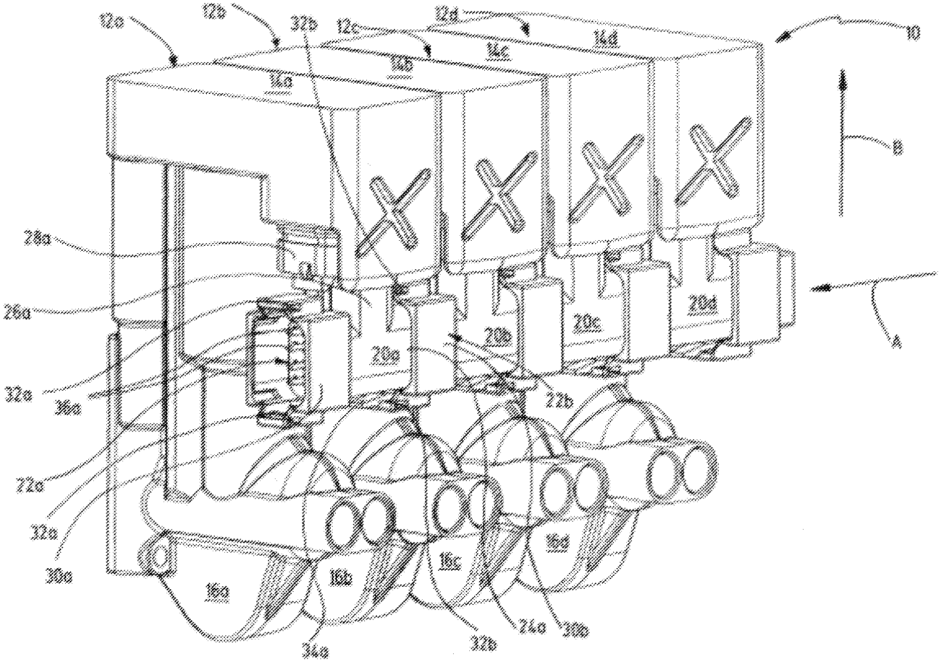
[0021] FIG. 1 an exemplary embodiment of a control device according to the invention comprising a plurality of control sections with connector parts attached thereto;
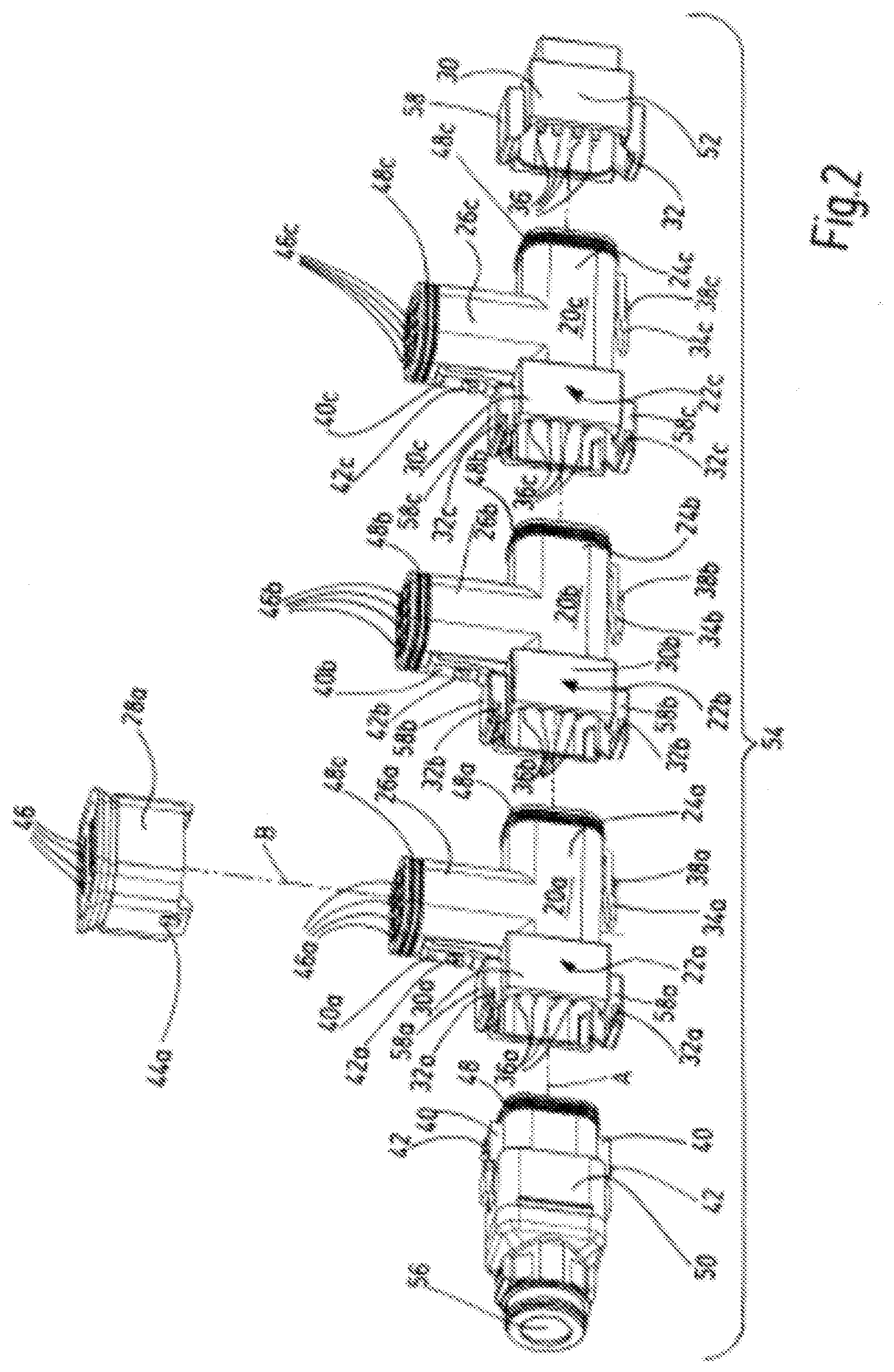
[0022] FIG. 2 in perspective view and separated from each other the connector parts including connector plug and terminating plug to form a connector rail, as well as a control section part to provide a connection to a corresponding control section;
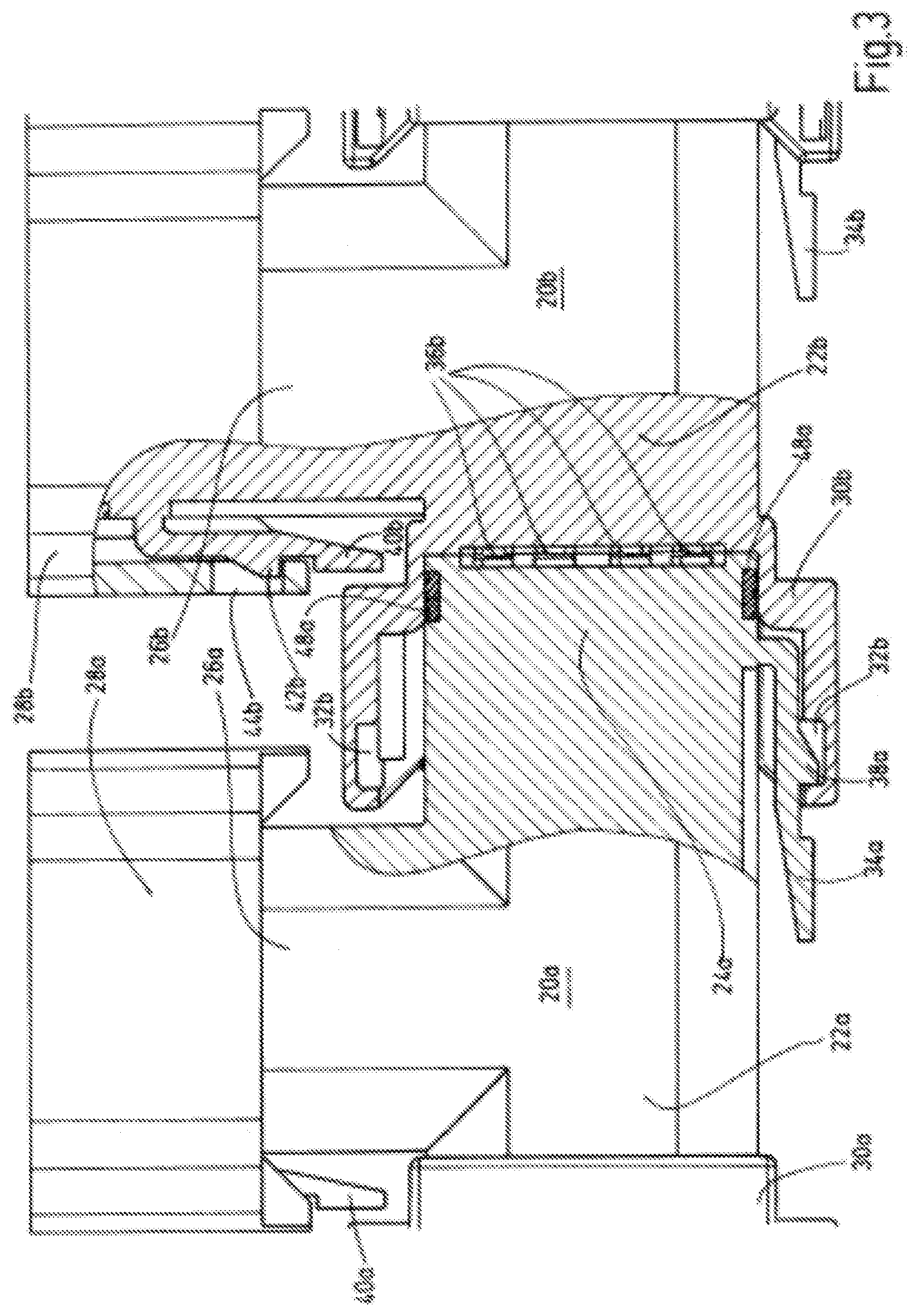
[0023] FIG. 3 an enlarged cross-section to illustrate the joining of two connector parts to each other and to a control section part each;
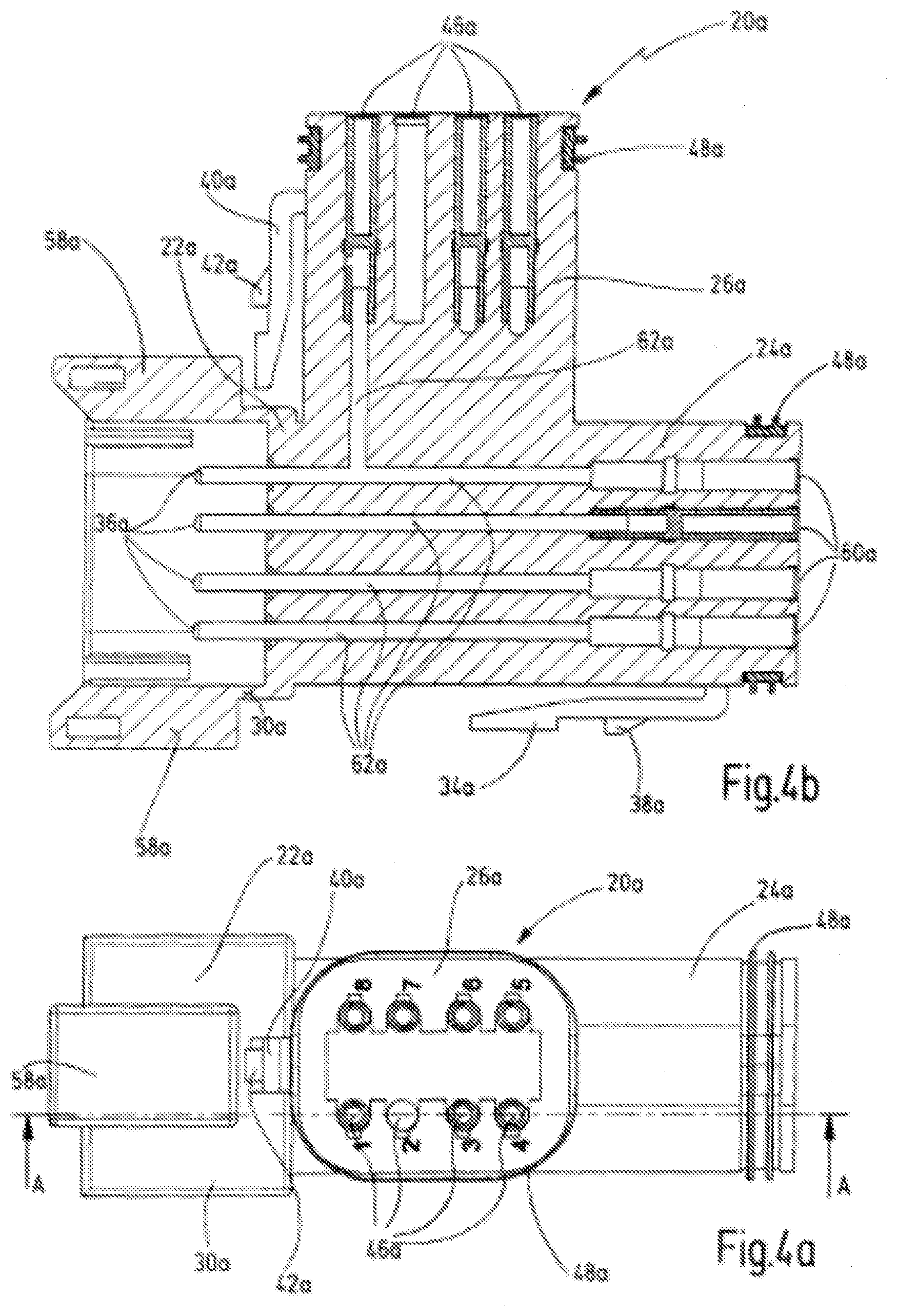
[0024] FIG. 4a a plan view from the top onto a connector part of FIGS. 1 and 2;
[0025] FIG. 4b a longitudinal cross-section through the connector part shown in
[0026] FIG. 4a to illustrate the interconnection inside the connector part;
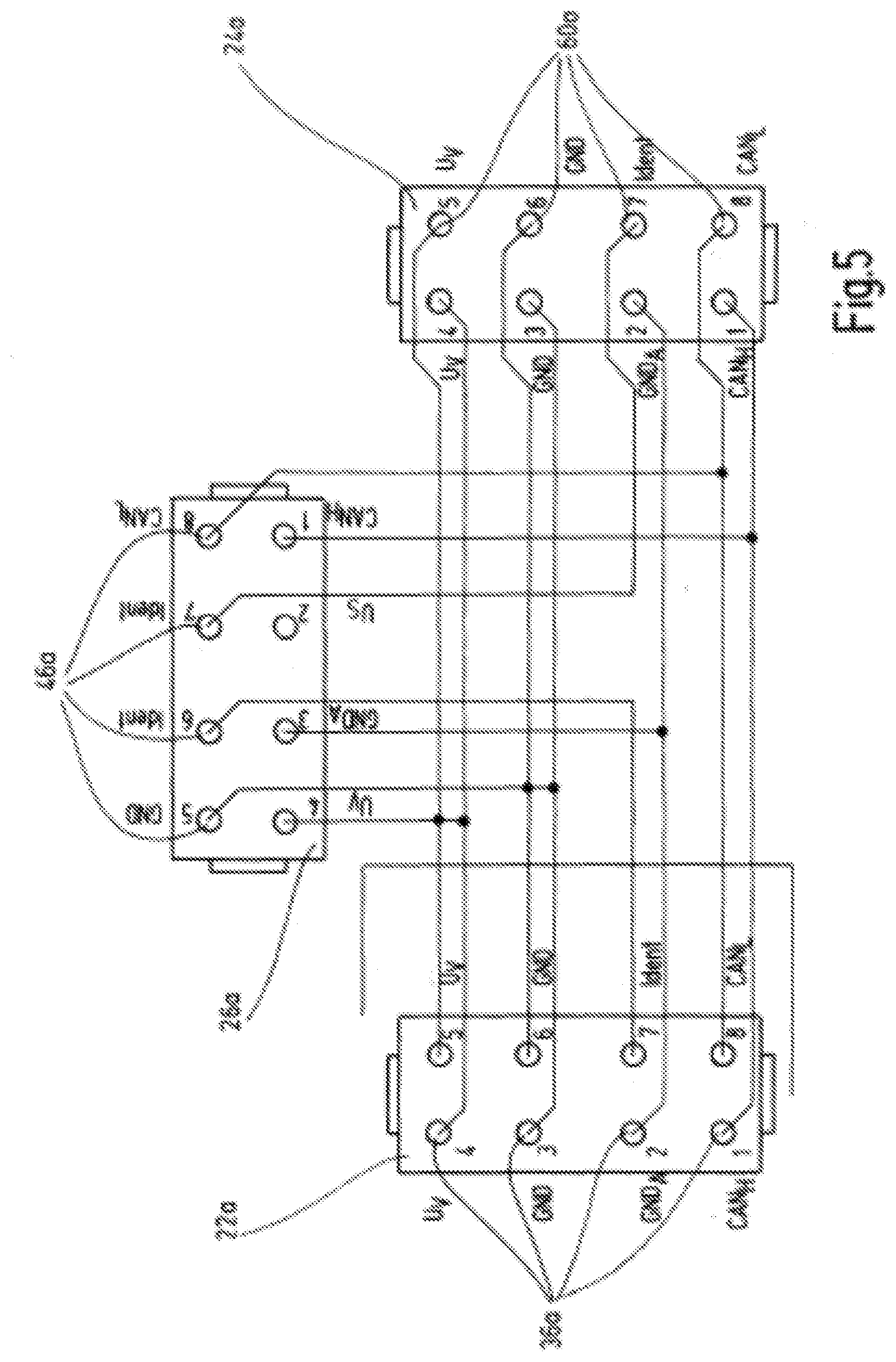
[0027] FIG. 5 a circuit diagram for the interconnection in the respective connector part; and
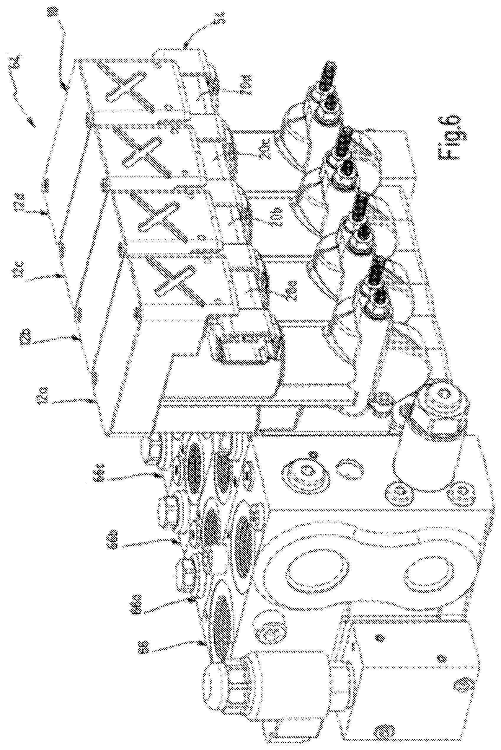
[0028] FIG. 6 an exemplary embodiment of a valve device according to the invention with a control device attached thereto.
[0029] FIG. 1 depicts in perspective view a control device 10 with four control sections 12a, 12b, 12c, 12d, which are arranged side-by-side and thus form a control block. It is of course evident that control sections 12a to 12d can be arranged side-by-side in any required number. In the exemplary embodiment shown the control sections 12a to 12d are all of the same design with a first housing part 14a to 14d, which in the depiction of FIG. 1 is shown at the top, and a second housing part 16a to 16d, which in the depiction of FIG. 1 is shown at the bottom, which comprise units of an electromagnetically operable actuator system and/or a sensor system.
[0030] Each of the control sections 12a to 12d, which is assembled from a first housing part 14a to 14d and a second housing part 16a to 16d, has a U-shaped design, wherein said U-shape defines the installation space. Disposed in said installation space are the connector parts 20a to 20d, each of which is attached with its upper end to the first housing part 14a to 14d of a control section 12a to 12d, whereas the lower end is free and unattached. The connector parts 22a to 22d are designed in a T-shape, comprising a plug part 22a, a socket part 24a and a contact part 26a. Via the plug parts 22a and the socket parts 24a the connector parts 20a to 20d are directly engaged with each other and form a daisy chain along a direction A.
[0031] Each of the connector parts 20a to 20d is connected to a control section part 28a of a control section 12a to 12d via the contact parts 26a and is detachably joined to the same. The control sections 12a to 12d are aligned in a further direction B, which extends vertical to direction A. Accordingly, the connection via the contact parts 26a of the individual connector parts 20a to 20d at the respective control section part 28a is aligned along the further direction B. It is evident that the two directions A, B may be aligned at an angle to each other that differs from 90.degree..
[0032] The plug parts 22a, 22b, the socket parts 24a and the contact parts 26a of the individual connector parts 20a to 20d have an essentially rectangular cross-section, wherein the plug part 22a, 22b is provided with an enlargement 30a, 30b that has an increased cross-section compared to the plug part 22a, 22b. Formed onto the enlargements 30a, 30b each are two seats 32a, 32b that point towards the inside and which are disposed on two opposing inner sides, shown in the representation of FIG. 1 top and bottom, of the enlargement 30a, 30b. The seats 32a, 32b serve as a clip connection with a latching part 34a of the next connector part 20a, as is shown in the clip connection of the first latching part 34a of the first connector part 20a with the second seat 32b, which is formed in the enlargement 30b of the second connector part 20b.
[0033] FIG. 2 depicts in perspective three connector parts 20a, 20b, 20c, the control section part 28a as well as a connector plug 50 and a terminating plug 52. The individual components are represented separately from each other but correspond to their arrangement in a later installation position to each other. The connecting plug 50, the connector parts 20a to 20c and the terminating plug 52 form a connector rail 54 that extends along the direction A. The control section part 28a may be connected along the further direction B to the first connector part 20a.
[0034] Arranged on the plug parts 22a to 22c are eight plug elements 36a to 36c each in two rows adjacent to each other, although only four plug elements 36a to 36c are visible on each respective plug part 22a to 22c in the illustration of FIG. 2. The socket elements formed in the socket parts 24a to 24c are obscured. To connect the socket elements of the socket part 24c of the third connector part 20c, plug elements 36 are provided on the terminating plug 52 and, correspondingly, socket elements that are obscured in the connector plug 50 in the illustration of FIG. 2 are provided for connecting the plug elements 36a on the plug part 22a of the first connector part 20a.
[0035] Eight contact elements 46, 46a to 46c each are disposed in two rows at the upper ends of the connector parts 20a to 20c and the control section part 28a. A resistor (not shown) is disposed in the terminating plug 52 for a CAN network. The connector plug 50 is provided with a connection opening 56 to which a corresponding cable for the supply of the connector rail 54 may be connected. The connector rail 54 serves not only to provide power but also to transmit data of the directional control valve operation of an electrohydraulic valve in a respective control section 12a to 12d (cf. FIG. 1).
[0036] To secure the mechanical attachment between the connector parts 20a to 20c as well as with the connector plug 50, the terminating plug 52 and the control section part 28a, clip connections are provided along both directions A and B. Each of the connector parts 20a to 20c is provided on the plug part 22a to 22c as well as on the terminating plug 52 with an enlargement 30, 30a to 30c compared to the cross-sectional shape defined by the respective part. Each enlargement 30, 30a to 30c is shaped in the likeness of a hollow profile section with enlargement parts 58, 58a to 58c, each of which is provided with a seat 32, 32a to 32c that faces to the inside. In a comparable manner the housing of the control section part 28a is enlarged compared to the cross-section of the associated contact part 48a of the first connector part 20a and is provided with further seats 44a.
[0037] The latching part that corresponds to the respective seat 30, 30a to 30c, 44a is formed on the respective other part of the joining region, that is, latching parts 34a to 34c at the socket parts 24a to 24c of the connector parts 20a to 20c as well as further latching parts 40, 40a to 40c at the connector plug 50 as well as on the contact parts 26a to 26c of the connector parts 20a to 20c. In the illustration of FIG. 2 the latching parts that are formed on the second, upper side of the socket parts 24a to 24c are missing. The latching parts 34a to 34c, 40, 40a to 40c are made to be elastic and are pivoted with one end on the corresponding part, and each is provided with a catch 38a to 38c and a further catch 42, 42a to 42c respectively.
[0038] Depending on the application of the control device 10 (cf. FIG. 1) the housings of the individual components 20a to 20d, 50, 52 as well as the control sections 12a to 12d (cf. FIG. 1) and the control section parts 28a are made from plastic, metal and/or a suitable compound material. In the end section of the contact parts 26a to 26c, the socket parts 24a to 24c as well as the connector plug 50, which are assigned to the respective joining region, a sealing device 48, 48a to 48c is disposed, which is made from an elastomeric material and has two parallel extending sealing beads. The terminating parts [sic] 20a to 20d shown in the exemplary embodiment of
[0039] FIGS. 1 and 2 are all of the same design. Nevertheless, different designs and combinations of connector parts of different kinds along the connector rail 54 are conceivable.
[0040] In cross-section and enlarged, FIG. 3 depicts the joining region between the first connector part 20a and the second connector part 20b. At the contact area between the socket part 24a and the plug part 22b the plug elements 36b are inserted into socket elements (not shown in detail) of the socket part 24a. The cross-section of FIG. 3 depicts one of the two rows comprising four plug elements 36b each. The seal 48a is inserted into a circumferential groove in the socket part 24a and is pressed with both its sealing beads against plug part 22b. The enlargement 30b adjoins the section of the plug part 22b where the seal 48a makes contact. The enlargement 30b encompasses the latching part 34a, formed on the socket part 24a, in such a way that the catch 38a, which is formed on the latching part 34a, engages with the seat 32b, which is formed in the enlargement 30b, and thus fixes the position of the two connector parts 20a, 20b to each other.
[0041] To release the bond of the two connector parts 20a, 20b, the latching part 34a is moved towards the socket part 24a, which moves the catch 38a out of the seat 32b, so that both connector parts 20a, 20b can be separated and released from each other again. In providing comparable latch attachments, FIG. 3 depicts the enlargement 30a on plug part 22a and the latching part 34b on connector part 20. The T-shaped connector parts 20a, 20b are attached via their contact parts 26a, 26b to the control section parts 28a, 28b of the control sections 12a to 12d (cf. FIG. 1), where a corresponding latch attachment is provided.
[0042] In contrast to the horizontally oriented latching parts 34a, 34b depicted in FIG. 3, the further latching parts 40a, 40b, formed on contact parts 26a, 26b, are oriented vertically and are pivoted with their upper end at the respective contact part 26a, 26b. The outward-directed further catch 42b engages with a further seat 44b, which is formed on the control section part 28b. The latched attachment may be released in that the further latching part 40b is moved in the direction of the contact part 26b and the control section part 28b is separated from the connector part 20b.
[0043] From the plan view of FIG. 4a it becomes apparent that the connector part 20a is comprised of the plug part 22a with the enlargement 30a and the enlargement part 58a, the socket part 24a with a seal 48a and the contact part 26a with the further latching part 40a and the further catch 42a as well as the seal 48a. The joining surface of the contact part 26a, which has a rectangular cross-section with rounded corners, is provided with eight contact elements 46a, which are arranged in two rows with four contact elements 46a each. The depiction of FIG. 4a shows the individual contact elements 46a with consecutive numbers.
[0044] It is apparent from the cross-section along the line A-A in FIG. 4b that the connector part 20a is block-shaped, wherein the plug elements 36a, the contact elements 46a and the socket elements 60a are connected to each other through conductor 62a and are interconnected as required (cf. FIG. 5). Moreover, the enlargement parts 58a on the enlargement 30a, the seal 48a on contact part 26a and on the socket part 24a as well as the two latching parts 34a, 40a, each with outward-oriented catches 38a, 42a, are clearly recognizable in the depiction of FIG. 4b.
[0045] The circuit diagram in FIG. 5 shows how the eight plug elements 36a, arranged on plug part 22a, are connected with the eight contact elements 46a, formed on contact part 26a, and the eight socket elements 60a formed on socket part 24a. The plug parts 26a, the socket parts 60a and the contact elements 46a, which are designated with the numbers 1 and 8 [sic] are interconnected and form a CAN bus control circuit comprised of a CAN.sub.H connection at number 1 and a CAN.sub.L connection at number 8. The plug parts 36a and the socket elements 60a, which are designated with the number 2, are connected to the contact element 46a with the number 3, forming the earth connection GND.sub.A for a sensor system. The contact element 46a designated with the number 2 is not used in the circuit diagram of FIG. 5, but it may be used as a connection for a control voltage U.sub.S (not shown). "H" is the abbreviation for "High" and "L" for "Low".
[0046] The plug elements 36a and the socket elements 60a designated with the number 7 are connected independently from each other to the contact elements 46a designated with the numbers 6 and 7, wherein each forms an identifier Ident for the position detection of the individual control sections 12a to 12d (cf. FIG. 1) in the valve block. The plug elements 36a and the socket elements 60a designated with the number 3 and 6 are connected together via a common conductor with the contact element 46a designated with the number 5 and form a double earth connection GND. In a comparable manner the plug elements 36a and the socket elements 60a designated with the numbers 4 and 5 are connected together via a common conductor with the contact element 46a designated with the number 4 and form a double power supply connection U.sub.V.
[0047] It is evident that the plug elements 36a, the socket elements 60a and the contact elements 46a may be formed and arranged in a number other than eight on the respective part 22a, 26a and 24a. The interconnections can be made as required and may differ from the circuit diagram shown in FIG. 5.
[0048] FIG. 6 shows in perspective view a valve device 64 with a total of five valve sections 66, 66a, 66b, 66c, one of which is obscured in the representation of FIG. 6. The valve sections 66, 66a-66c define with their cuboid shape the space required for individual valves and form overall in a side-by-side arrangement a valve block. A control device 10, comparable to that depicted in FIG. 1, is provided for the control and monitoring of the valve device 64 and is disposed on the side of the valve block. One control section 12a to 12d is assigned and individually connected to each valve section 66a-66c. A further valve section 66, which is arranged in the representation of FIG. 6 on the left, adjacent to the first valve section 66a, is shown without separate control section. It is conceivable to arrange an additional control section to the left of the first control section 12a and to attach it to the first control section 12a and to connect it to the further valve section 66.
[0049] The valve sections 66, 66a-66c of the valve device 64 can be individually controlled and monitored via the connector rail 54, which is formed by the individual connector parts 20a to 20d. To this end the individual control sections 12a to 12d are provided with an electromagnetically operable actuator system and/or sensor system (not shown). The individual valve sections 66, 66a-66c of the valve block and the individual control sections 12a to 12d of the control block of the control device 10 may be individually manufactured, stored and/or sold. The modular design of the valve device 64 with the control device 10 makes it possible to assemble individual and application-specific designs of the valve block of the valve device 64 for different industrial applications.
* * * * *
D00000
D00001
D00002
D00003
D00004
D00005
D00006
XML
uspto.report is an independent third-party trademark research tool that is not affiliated, endorsed, or sponsored by the United States Patent and Trademark Office (USPTO) or any other governmental organization. The information provided by uspto.report is based on publicly available data at the time of writing and is intended for informational purposes only.
While we strive to provide accurate and up-to-date information, we do not guarantee the accuracy, completeness, reliability, or suitability of the information displayed on this site. The use of this site is at your own risk. Any reliance you place on such information is therefore strictly at your own risk.
All official trademark data, including owner information, should be verified by visiting the official USPTO website at www.uspto.gov. This site is not intended to replace professional legal advice and should not be used as a substitute for consulting with a legal professional who is knowledgeable about trademark law.