Sliding Camshaft Assembly
Nguyen; Hong Wai ; et al.
U.S. patent application number 16/250591 was filed with the patent office on 2020-07-23 for sliding camshaft assembly. The applicant listed for this patent is GM Global Technology Operations LLC. Invention is credited to Domenic Certo, Bradley R. Kaan, Joseph J. Moon, Hong Wai Nguyen.
| Application Number | 20200232348 16/250591 |
| Document ID | / |
| Family ID | 71402953 |
| Filed Date | 2020-07-23 |


| United States Patent Application | 20200232348 |
| Kind Code | A1 |
| Nguyen; Hong Wai ; et al. | July 23, 2020 |
SLIDING CAMSHAFT ASSEMBLY
Abstract
A camshaft assembly includes an actuator and an axially moveable structure mounted to a base shaft wherein the axially moveable structure includes a plurality of lobe packs and a cam barrel. The axially movable structure moves along the base shaft in the axial direction along a longitudinal axis of the base shaft, but is rotationally fixed to the base shaft. The barrel cam includes an inner wall and an outer wall which defines a control groove therebetween. The control groove further defines first and second regions wherein the first region includes a fixed narrow control groove width and the second region includes a progressively decreasing control groove width. The actuator shifts the axially moveable structure relative to the base shaft between a first position and a second position. A recess is defined in the outer wall such that the recess is disposed adjacent to the first region.
| Inventors: | Nguyen; Hong Wai; (Troy, MI) ; Certo; Domenic; (Niagara Falls, CA) ; Kaan; Bradley R.; (Oxford, MI) ; Moon; Joseph J.; (BEVERLY HILLS, MI) | ||||||||||
| Applicant: |
|
||||||||||
|---|---|---|---|---|---|---|---|---|---|---|---|
| Family ID: | 71402953 | ||||||||||
| Appl. No.: | 16/250591 | ||||||||||
| Filed: | January 17, 2019 |
| Current U.S. Class: | 1/1 |
| Current CPC Class: | F01L 2013/0078 20130101; F01L 2013/0052 20130101; F01L 13/0036 20130101; F01L 2001/0471 20130101; F01L 1/047 20130101 |
| International Class: | F01L 1/047 20060101 F01L001/047; F01L 13/00 20060101 F01L013/00 |
Claims
1. A camshaft assembly comprising: a base shaft extending along a longitudinal axis; an axially movable structure mounted on the base shaft and being axially movable relative to the base shaft between a first position and a second position via an actuator while also being rotationally fixed to the base shaft, the axially movable structure includes: a plurality of lobe packs, each of the plurality of lobe packs including a plurality of cam lobes; and a barrel cam having a control groove defined between an inner wall and an outer wall of the barrel cam such that the control groove further includes a first region having a fixed narrow groove width between the inner and outer walls and a second region having an enlarged groove width between the inner wall and the outer walls; and a recess is defined in the outer wall of the barrel cam such that the recess is disposed adjacent to the first region; wherein the recess is defined in the first region of the barrel cam, and wherein the fixed narrow groove and the enlarged groove are aligned circumferentially around the longitudinal axis at an axial position, such that the control groove does not circumferentially overlap with itself.
2. The camshaft assembly of claim 1 further comprising a sensor configured to align with the axially moveable structure along a first sensor path when the axially moveable structure moves to the first position, and the sensor is configured to align with the axially moveable structure along a second sensor path when the axially moveable structure moves to the second position.
3. The camshaft assembly as defined in claim 2 wherein the first sensor path overlays the outer wall and the recess defined in the outer wall.
4. The camshaft assembly as defined in claim 3 wherein the second sensor path overlays the control groove and the outer wall.
5. The camshaft assembly of claim 4, further comprising a control module in communication with the actuator and the sensor.
6. The camshaft assembly of claim 5, wherein each lobe pack in the plurality of lobe packs includes a first cam lobe adjacent to a second cam lobe.
7. The camshaft assembly of claim 6, wherein the first cam lobe is configured to engage with an engine valve when the axially moveable structure is in the first position.
8. The camshaft assembly of claim 7 wherein the recess and outer wall are configured to communicate to an engine control module via the sensor to detect the first position of the axially movable structure when the recess and the outer wall are aligned with the sensor in a first sensor path.
9. The camshaft assembly of claim 8 wherein the control groove and the outer wall are configured to communicate to an engine control module via the sensor to detect the second position of the axially movable structure when control groove and the outer wall are aligned with the sensor in a second sensor path.
10. An engine assembly, comprising: an internal combustion engine including a first cylinder, a second cylinder, a first valve operatively coupled to the first cylinder, and a second valve operatively coupled to the second cylinder; an engine control module; a camshaft assembly operatively coupled to the first and second valves, wherein the camshaft assembly includes: a base shaft extending along a longitudinal axis, the base shaft being configured to rotate about the longitudinal axis; an axially movable structure being axially movable between a first position and a second position on the base shaft and being rotationally fixed to the base shaft, wherein the axially movable structure further includes; a barrel cam having a control groove defined between an inner wall and an outer wall of the barrel cam, the control groove defining a fixed narrow groove width throughout a first region and an enlarged groove width which progressively varies in at least a portion of a second region of the barrel cam, wherein the fixed narrow groove and the enlarged groove are aligned circumferentially around the longitudinal axis at an axial position, such that the control groove does not circumferentially overlap with itself; and an actuator configured to move the axially movable structure between the first and second positions via the control groove in the barrel cam according to an output signal from the engine control module; and a sensor configured to send a first set of data to the engine control module when the axial moveable structure is a first position and configured to send a second set of data to the engine control module when the axial moveable structure is in the second position, wherein a recess is defined in the outer wall of the barrel cam and is aligned with the sensor when the axially moveable structure is in the first position.
11. The engine assembly of claim 10 wherein the enlarged groove width of the second region is greater than the fixed narrow groove width of the first region.
12. The engine assembly of claim 11, wherein the axially moveable structure further includes a plurality of lobe packs which are configured to rotate synchronously with the barrel cam when the axially movable structure rotates together with the base shaft.
13. The engine assembly of claim 12, wherein the actuator includes at least one pin configured to move between a retracted and extended positions in response to the output signal from the engine control module.
14. The engine assembly of claim 13, wherein each lobe pack in the plurality of lobe packs includes a first cam lobe being adjacent to a second cam lobe.
15. The engine assembly of claim 14 wherein the first cam lobe has a first maximum lobe height, the second cam lobe has a second maximum lobe height, and the first maximum lobe height is different from the second maximum lobe height.
Description
TECHNICAL FIELD
[0001] The present disclosure relates to a sliding camshaft for a vehicle engine.
BACKGROUND
[0002] In modern internal combustion engines, variable valve drives, with which different valve strokes can be set at the gas exchange valves of the internal combustion engine, are used to optimize the charge movement in the combustion chamber. The axial displacement of the cam causes a different valve stroke to be set at the respective gas exchange valve. The traditional valve drive includes a sliding cam which is mounted in a rotationally fixed but axially displaceable fashion on a camshaft wherein the sliding cam may further include a cam barrel with a plurality of grooves, and in which in order to bring about axial displacement of the sliding cam an actuator having a plurality of pins which can be activated is provided. The cam barrel may have a first, right-handed groove and a second, left-handed groove which are arranged one next to the other on the circumference of the cam barrel and merge with a common run-out groove. The pins of the actuator interact with the grooves of the cam barrel.
[0003] In addition, a valve drive is already known in which the grooves of the cam barrel are positioned one behind the other on the circumference of the cam barrel, specifically a first groove for axial displacement of the sliding cam in a first direction and a second groove for axial displacement of the sliding cam in an opposing second direction. In this valve drive, the actuator also has a plurality of pins which can be activated in order to bring about axial displacement of the sliding cam, specifically a first pin for axial displacement of the sliding cam in the two directions about a first axial segment and a second pin for axial displacement of the sliding cam in the two directions about a second axial segment.
[0004] For the engine control of an internal combustion engine having such a valve drive which has at least one displaceable sliding cam, it is necessary to have knowledge of the relative position of the sliding cam on the camshaft and therefore of the cam lobes relative to the gas exchange valve of the internal combustion engine which is to be activated. Hitherto, it was difficult to detect in a certain and reliable way the relative position of the sliding cam on the camshaft and therefore the relative position of the cam tracks with respect to the gas exchange valve which is to be activated.
SUMMARY
[0005] In one embodiment of the present disclosure, a camshaft assembly is provided wherein the camshaft assembly includes an actuator and an axially moveable structure mounted to a base shaft wherein the axially moveable structure includes a plurality of lobe packs and a cam barrel. The axially movable structure moves along the base shaft in the axial direction along a longitudinal axis of the base shaft, but is rotationally fixed to the base shaft. The barrel cam includes an inner wall and an outer wall which defines a control groove therebetween. The control groove further includes first and second regions wherein the second region defines a fixed narrow control groove width and the first region includes a progressively changing control groove width. The actuator shifts the axially moveable structure relative to the base shaft between a first position and a second position. A recess is defined in the outer wall of the barrel such that the recess is disposed adjacent to the second region of the control groove.
[0006] The camshaft assembly may further include a sensor configured to align with the axially moveable structure along a first sensor path when the axially moveable structure moves to the first position. The aforementioned sensor may also be configured to align with the axially moveable structure along a second sensor path when the axially moveable structure moves to the second position. The first sensor path overlays the outer wall and the recess defined in the outer wall. The second sensor path overlays the control groove and the outer wall. However, it is understood that the recess is disposed outside of the second sensor path. Thus, the aforementioned camshaft assembly of the present disclosure may also include an engine control module in communication with the actuator and the sensor.
[0007] The recess and outer wall may be configured to communicate to an engine control module via a sensor to detect/confirm the first position of the axially movable structure when the recess and the outer wall are aligned with the sensor in a first sensor path. The sensor is configured to transmit feedback signals (in the form of a first set of data) to the engine control module according to the structure of the barrel cam along the first sensor path. More specifically, the recess and outer wall are configured to communicate with an engine control module via a sensor to detect/confirm the first position of the axially movable structure when the recess and the outer wall are aligned with the sensor in a first sensor path.
[0008] Similarly, the control groove and the outer wall may also be configured to communicate to an engine control module via the sensor to detect/confirm the second position of the axially movable structure when control groove and the outer wall are aligned with the sensor in a second sensor path. The sensor is configured to transmit feedback signals (in the form of a second set of data) to the engine control module according to the structure of the barrel cam along the second sensor path.
[0009] Each lobe pack in the plurality of lobe packs includes a first cam lobe adjacent to a second cam lobe in the axial direction. The first cam lobe is configured to engage with the engine valve when the axially moveable structure is in the first position. Similarly, the second cam lobe is configured to engage with the engine valve when the axially moveable structure is in the second position.
[0010] In yet another embodiment of the present disclosure, an engine assembly includes an engine control module, an internal combustion engine, a camshaft assembly, an actuator and a sensor. The internal combustion engine includes a first cylinder, a second cylinder, a first valve operatively coupled to the first cylinder, and a second valve operatively coupled to the second cylinder. The camshaft assembly may be coupled to the first and second valves of the internal combustion engine. The camshaft assembly further includes a base shaft and an axially moveable structure mounted on the base shaft. The base shaft may extend along a longitudinal axis and is configured to rotate about the longitudinal axis. The axially moveable structure is configured to move between a first position and a second position on the base shaft yet the axially moveable structure is rotationally fixed to the base shaft. The aforementioned axially moveable structure includes a barrel cam having a control groove defined between an inner wall and an outer wall of the barrel cam. The control groove may define a fixed narrow groove width throughout a second region and may define an enlarged groove width which progressively varies in at least a portion of a first region of the barrel cam.
[0011] The actuator is configured to move the axially movable structure between the first and second positions via a pin of the actuator in engagement with the control groove in the barrel cam--according to an output signal from the engine control module. The sensor is configured to send a first set of data (feedback signal) to the engine control module when axial moveable structure is in the first position. The sensor is also configured to send a second set of data (feedback signal) to the engine control module when the axial moveable structure is in the second position. It is understood that a recess is defined in the outer wall of the barrel cam and is aligned with the sensor when the axially moveable structure is in the first position.
[0012] With respect to the aforementioned engine assembly, the enlarged groove width of the first region may be greater than the fixed narrow groove width of the second region. As indicated, the actuator may include at least one pin configured to move between the retracted and extended positions (where the pin engages with the control groove) in response to the output signal from the engine control module. Moreover, the axially moveable structure may further include a plurality of lobe packs which are configured to rotate synchronously with the barrel cam when the axially movable structure rotates together with the base shaft. Each lobe pack in the plurality of lobe packs includes a first cam lobe being adjacent to a second cam lobe. The first cam lobe has a first maximum lobe height, the second cam lobe has a second maximum lobe height, and the first maximum lobe height is different from the second maximum lobe height.
[0013] The present disclosure and its particular features and advantages will become more apparent from the following detailed description considered with reference to the accompanying drawings.
BRIEF DESCRIPTION OF THE DRAWINGS
[0014] These and other features and advantages of the present disclosure will be apparent from the following detailed description, best mode, claims, and accompanying drawings in which:
[0015] FIG. 1A is a schematic diagram of a vehicle including an engine assembly.
[0016] FIG. 1B is an illustration of a sliding camshaft cover with position shifting actuators and position detection sensors.
[0017] FIG. 2A is an isometric view of a barrel cam for a first embodiment camshaft assembly in a first position.
[0018] FIG. 2B is an isometric view of the barrel cam of FIG. 2A for the first embodiment camshaft assembly in a second position.
[0019] FIG. 2C is a schematic view of a camshaft assembly of the engine assembly of FIGS. 2A-2B (as the camshaft assembly rotates relative to an actuator pin) in accordance with an example, non-limiting embodiment of the present disclosure.
[0020] FIG. 2D is a schematic view of a barrel cam for yet another example camshaft assembly according to the present disclosure.
[0021] FIG. 3 is a schematic view of the example, non-limiting camshaft assembly in FIG. 2A-2C wherein the camshaft assembly is in a first position.
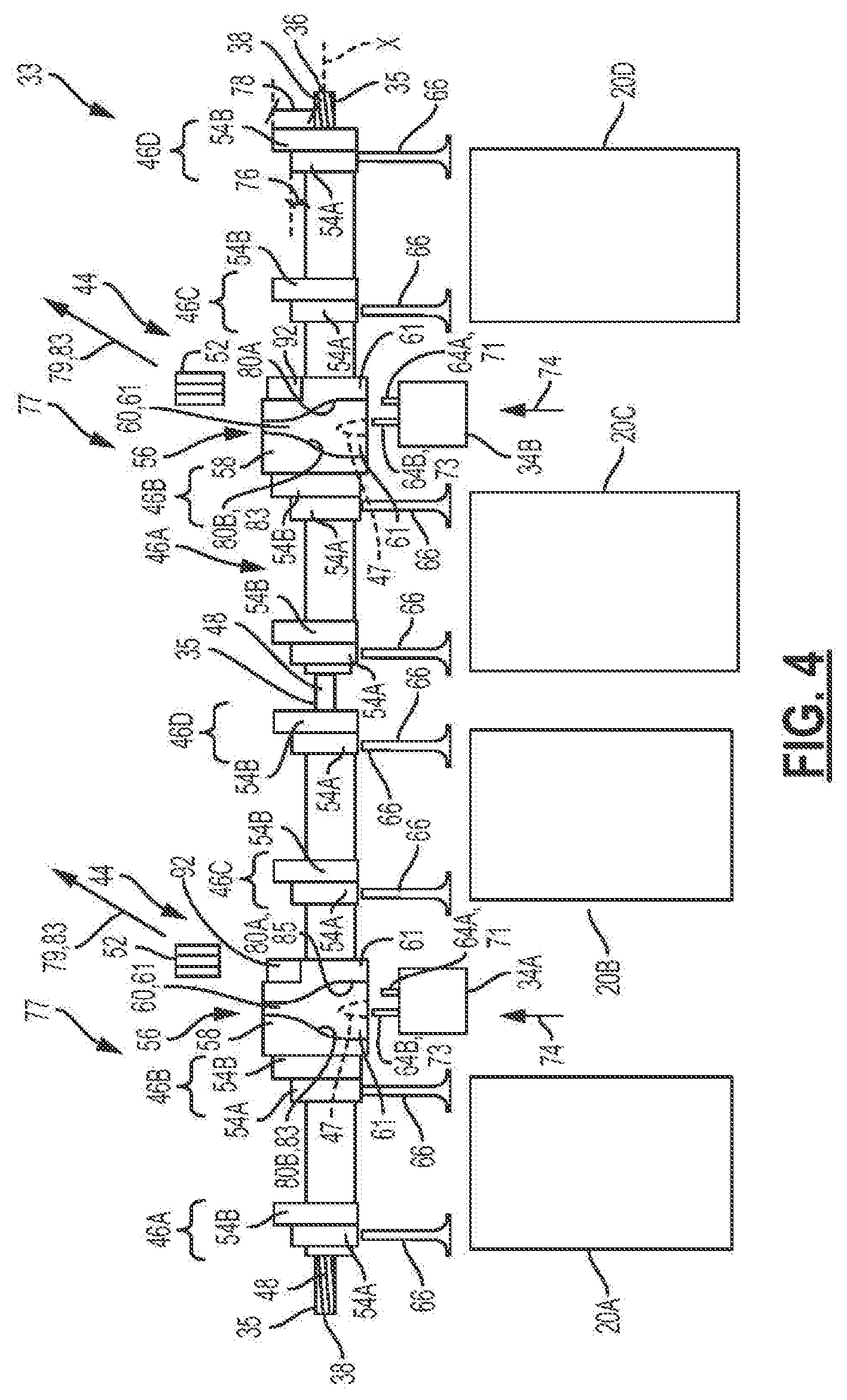
[0022] FIG. 4 is a schematic view of the example, non-limiting camshaft assembly in FIG. 2A-2C wherein the camshaft assembly is in a second position.
[0023] Like reference numerals refer to like parts throughout the description of several views of the drawings.
DETAILED DESCRIPTION
[0024] Reference will now be made in detail to presently preferred compositions, embodiments and methods of the present disclosure, which constitute the best modes of practicing the present disclosure presently known to the inventors. The figures are not necessarily to scale. However, it is to be understood that the disclosed embodiments are merely exemplary of the present disclosure that may be embodied in various and alternative forms. Therefore, specific details disclosed herein are not to be interpreted as limiting, but merely as a representative basis for any aspect of the present disclosure and/or as a representative basis for teaching one skilled in the art to variously employ the present disclosure.
[0025] Except in the examples, or where otherwise expressly indicated, all numerical quantities in this description indicating amounts of material or conditions of reaction and/or use are to be understood as modified by the word "about" in describing the broadest scope of the present disclosure. Practice within the numerical limits stated is generally preferred. Also, unless expressly stated to the contrary: percent, "parts of," and ratio values are by weight; the description of a group or class of materials as suitable or preferred for a given purpose in connection with the present disclosure implies that mixtures of any two or more of the members of the group or class are equally suitable or preferred; the first definition of an acronym or other abbreviation applies to all subsequent uses herein of the same abbreviation and applies mutatis mutandis to normal grammatical variations of the initially defined abbreviation; and, unless expressly stated to the contrary, measurement of a property is determined by the same technique as previously or later referenced for the same property.
[0026] It is also to be understood that this present disclosure is not limited to the specific embodiments and methods described below, as specific components and/or conditions may, of course, vary. Furthermore, the terminology used herein is used only for the purpose of describing particular embodiments of the present disclosure and is not intended to be limiting in any way.
[0027] It must also be noted that, as used in the specification and the appended claims, the singular form "a," "an," and "the" comprise plural referents unless the context clearly indicates otherwise. For example, reference to a component in the singular is intended to comprise a plurality of components.
[0028] The term "comprising" is synonymous with "including," "having," "containing," or "characterized by." These terms are inclusive and open-ended and do not exclude additional, un-recited elements or method steps.
[0029] The phrase "consisting of" excludes any element, step, or ingredient not specified in the claim. The phrase "consisting essentially of" limits the scope of a claim to the specified materials or steps, plus those that do not materially affect the basic and novel characteristic(s) of the claimed subject matter.
[0030] The terms "comprising", "consisting of", and "consisting essentially of" can be alternatively used. Where one of these three terms is used, the presently disclosed and claimed subject matter can include the use of either of the other two terms.
[0031] Throughout this application, where publications are referenced, the disclosures of these publications in their entireties are hereby incorporated by reference into this application to more fully describe the state of the art to which this present disclosure pertains.
[0032] The following detailed description is merely exemplary in nature and is not intended to limit the present disclosure or the application and uses of the present disclosure. Furthermore, there is no intention to be bound by any theory presented in the preceding background or the following detailed description.
[0033] Referring to the drawings, wherein like reference numbers correspond to like or similar components throughout the several figures, FIG. 1A schematically illustrates a vehicle 10 such as a car, truck or motorcycle. The vehicle 10 includes an engine assembly 12. The engine assembly 12 includes an internal combustion engine 14 and a control module 16, such an engine control module (ECU), in electronic communication with the internal combustion engine 14. The terms "control module," "module," "control," "controller," "control unit," "processor" and similar terms mean any one or various combinations of one or more of Application Specific Integrated Circuit(s) (ASIC), electronic circuit(s), central processing unit(s) (preferably microprocessor(s)) and associated memory and storage (read only, programmable read only, random access, hard drive, etc.) executing one or more software or firmware programs or routines, combinational logic circuit(s), sequential logic circuit(s), input/output circuit(s) and devices, appropriate signal conditioning and buffer circuitry, and other components to provide the described functionality. "Software," "firmware," "programs," "instructions," "routines," "code," "algorithms" and similar terms mean any controller executable instruction sets including calibrations and look-up tables. The control module 16 may have a set of control routines executed to provide the desired functions. Routines are executed, such as by a central processing unit, and are operable to monitor inputs from sensing devices and other networked control modules, and execute control and diagnostic routines to control operation of actuators. Routines may be executed based on events or at regular intervals.
[0034] The internal combustion engine 14 includes an engine block 18 defining a plurality of cylinders 20A, 20B, 20C, and 20D. In other words, the engine block 18 includes a first cylinder 20A, a second cylinder 20B, a third cylinder 20C, and a fourth cylinder 20D. Although FIG. 1A schematically illustrates four cylinders, the internal combustion engine 14 may include more or fewer cylinders. The cylinders 20A, 206, 20C, and 20D are spaced apart from each other but may be substantially aligned along an engine axis E. Each of the cylinders 20A, 20B, 20C, and 20D is configured, shaped and sized to receive a piston (not shown). The pistons are configured to reciprocate within the cylinders 20A, 20B, 20C, and 20D. Each cylinder 20A, 20B, 20C, 20D defines a corresponding combustion chamber 22A, 22B, 22C, 22D. During operation of the internal combustion engine 14, an air/fuel mixture is combusted inside the combustion chambers 22A, 22B, 22C, and 22D in order to drive the pistons in a reciprocating manner. The reciprocating motion of the pistons drives a crankshaft (not shown) operatively connected to the wheels (not shown) of the vehicle 10. The rotation of the crankshaft can cause the wheels to rotate, thereby propelling the vehicle 10.
[0035] In order to propel the vehicle 10, an air/fuel mixture should be introduced into the combustion chambers 22A, 22B, 22C, and 22D. To do so, the internal combustion engine 14 includes a plurality of intake ports 24 fluidly coupled to an intake manifold (not shown). In the depicted embodiment, the internal combustion engine 14 includes two intake ports 24 in fluid communication with each combustion chamber 22A, 22B, 22C, and 22D. However, the internal combustion engine 14 may include more or fewer intake ports 24 per combustion chamber 22A, 22B, 22C, and 22D. The internal combustion engine 14 includes at least one intake port 24 per cylinder 20A, 20B, 20C, 20D.
[0036] The internal combustion engine 14 further includes a plurality of intake valves 26 configured to control the flow of inlet charge through the intake ports 24. The number of intake valves 26 corresponds to the number of intake ports 24. Each intake valve 26 is at least partially disposed within a corresponding intake port 24. In particular, each intake valve 26 is configured to move along the corresponding intake port 24 between an open position and a closed position. In the open position, the intake valve 26 allows inlet charge to enter a corresponding combustion chamber 22A, 22B, 22C, or 22D via the corresponding intake port 24. Conversely, in the closed position, the intake valve 26 precludes the inlet charge from entering the corresponding combustion chamber 22A, 22B, 22C, or 22D via the intake port 24.
[0037] As discussed above, the internal combustion engine 14 can combust the air/fuel mixture once the air/fuel mixture enters the combustion chamber 22A, 22B, 22C, or 22D. For example, the internal combustion engine 14 can combust the air/fuel mixture in the combustion chamber 22A, 22B, 22C, or 22D using an ignition system (not shown). This combustion generates exhaust gases. To expel these exhaust gases, the internal combustion engine 14 defines a plurality of exhaust ports 28. The exhaust ports 28 are in fluid communication with the combustion chambers 22A, 22B, 22C, or 22D. In the depicted embodiment, two exhaust ports 28 are in fluid communication with each combustion chamber 22A, 22B, 22C, or 22D. However, more or fewer exhaust ports 28 may be fluidly coupled to each combustion chamber 22A, 226, 22C, or 22D. The internal combustion engine 14 includes at least one exhaust port 28 per cylinder 20A, 20B, 20C, or 20D.
[0038] The internal combustion engine 14 further includes a plurality of exhaust valves 30 in fluid communication with the combustion chambers 22A, 22B, 22C, or 22D. Each exhaust valve 30 is at least partially disposed within a corresponding exhaust port 28. In particular, each exhaust valve 30 is configured to move along the corresponding exhaust port 28 between an open position and a closed position. In the open position, the exhaust valve 30 allows the exhaust gases to escape the corresponding combustion chamber 22A, 228, 22C, or 22D via the corresponding exhaust port 28. The vehicle 10 may include an exhaust system (not shown) configured to receive and treat exhaust gases from the internal combustion engine 14. In the closed position, the exhaust valve 30 precludes the exhaust gases from exiting the corresponding combustion chamber 22A, 22B, 22C, or 22D via the corresponding exhaust port 28.
[0039] As discussed in detail below, intake valve 26 and exhaust valve 30 (FIG. 1A) can also be generally referred to as engine valves 66 (FIGS. 3-4) or simply valves. Each valve 66 (FIGS. 3-4) is operatively coupled or associated with a cylinder 20A, 20B, 20C, or 20D. Accordingly, the valves 66 (FIGS. 3-4) are configured to control fluid flow (i.e., air/fuel mixture for intake valves 26 and exhaust gas for exhaust valve 30) to the corresponding cylinder 20A, 20B, 20C, or 20D.
[0040] With further reference to FIG. 1A, the engine assembly 12 further includes a valvetrain system 32 configured to control the operation of the intake valves 26 and exhaust valves 30. Specifically, the valvetrain system 32 can move the intake valves 26 and exhaust valves 30 between the open and closed positions based, at least in part, on the operating conditions of the internal combustion engine 14 (e.g., engine speed). The valvetrain system 32 includes one or more camshaft assemblies 33 (see FIGS. 3-4) substantially parallel to the engine axis E. In the depicted embodiment, the valvetrain system 32 includes two camshaft assemblies 33. One camshaft assembly 33 is configured to control the operation of the intake valves 26, and the other camshaft assembly 33 can control the operation of the exhaust valves 30.
[0041] Referring now to FIG. 1B, an illustration of a sliding camshaft cover 40 with position shifting actuators (34A-34D) and position detection sensors 52 in accordance with aspects of the exemplary embodiment is provided. The sliding camshaft cover 40 shrouds the intake 82 and exhaust 84 sliding camshafts as protection from the outside environment containments and retain oil splatter produced by the operation of the engine. The position detection sensors 52 are disposed in the sliding camshaft cover 40 proximate to at least one position shifting slot such that the position of at least one barrel cam 56, e.g., camshaft barrel (56), can be detected by the position detection sensor(s) 52 as described herein. The position detection sensors 52 may be of the type that are used for position detection suitable for an engine environment including, but not limited to, a Hall Effect sensor.
[0042] With reference back to FIG. 1A, in addition to the camshaft assemblies 33, the valvetrain assembly 32 includes a plurality of actuators 34A, 34B, such as solenoids, in communication with the control module 16. The actuators 34A, 34B may be electronically connected to the control module 16 and may therefore be in electronic communication with the control module 16. The control module 16 may be part of the valvetrain system 32. In the depicted embodiment, the valvetrain system 32 includes first, second actuators 34A, 34B. Actuators 34A and 34B are operatively associated with the first and second cylinders 20A, 20B wherein actuator 34A shifts the lobes in the forward direction and actuator 34B shifts the lobes back in the rearward direction. Similarly, actuators 34C and 34D are operatively associated with the third and fourth cylinders 20C, 20D wherein actuator 34C shifts the lobes two steps in the forward direction and actuator 34D shifts the lobes back in the rearward direction.
[0043] Referring now to FIGS. 3-4, a camshaft assembly 33 includes an actuator 34A, 34B (FIGS. 3-4) and an axially moveable structure 44 mounted to a base shaft 35 wherein the axially moveable structure 44 includes a plurality of lobe packs 46 and a barrel cam 56. The axially movable structure 44 moves along the base shaft 35 in the axial direction along a longitudinal axis x, 37 of the base shaft 35, but is rotationally fixed to the base shaft 35. The barrel cam 56 includes an inner wall 94 and an outer wall 90 which defines a control groove 60 therebetween. The control groove 60 further includes first and second regions wherein the second region 69 defines a fixed narrow control groove width 72 and the first region 67 includes a progressively changing control groove width 70. The actuator 34A, 34B (FIGS. 3-4) shifts the axially moveable structure 44 relative to the base shaft 35 between a first position 75 and a second position 77. A recess 92 is defined in the outer wall 90 of the barrel cam 56 such that the recess 92 is disposed adjacent to the second region 69 of the control groove 60 (FIGS. 2A-2C).
[0044] The camshaft assembly 33 may further include a sensor 52 configured to align with the axially moveable structure 44 along a first sensor path 88 (FIG. 2A) when the axially moveable structure 44 moves to the first position 75 (FIG. 3). The aforementioned sensor 52 may also be configured to align with the axially moveable structure 44 along a second sensor path 86 (FIG. 28) when the axially moveable structure 44 moves to the second position 77 (FIG. 4). As shown in FIG. 2A, the first sensor path 88 overlays the outer wall 90 and the recess 92 defined in the outer wall 90. The second sensor path 86 overlays the control groove 60 and the outer wall 90. (see FIG. 2B). However, it is understood that the recess 92 is disposed outside of the second sensor path 86.
[0045] The engine control module 16 of FIG. 1A is in communication with the actuator 34A, 34B (FIGS. 3-4) and the sensor 52. However, the engine control module 16 is also in communication with the recess 92 and outer wall 90 via a sensor 52 to detect/confirm the first position 75 of the axially movable structure when the axial moveable structure is in the first position 75 (FIG. 3). In the arrangement shown in FIG. 3, the recess 92 and the outer wall 90 are aligned with the sensor 52 in a first sensor path 88 (see FIG. 2A). The sensor 52 is configured transmit feedback signals 79 (in the form of a first set of data 81) to the engine control module 16 according to the structure of the barrel cam 56 along the first sensor path 88. More specifically, the recess 92 and outer wall 90 are configured to communicate with an engine control module 16 via a sensor 52 to detect/confirm the first position 75 of the axially movable structure 44 when the recess 92 and the outer wall 90 are aligned with the sensor 52 in a first sensor path 88.
[0046] Similarly, the control groove 60 and the outer wall 90 may also be configured to communicate to the engine control module 16 via the sensor 52 to detect/confirm the second position 77 of the axially movable structure 44 when control groove 60 and the outer wall 90 are aligned with the sensor 52 in a second sensor path 86. (See FIGS. 2B, 4). The sensor 52 is configured to transmit feedback signals 79 (in the form of a second set of data 83) to the engine control module 16 according to the structure of the barrel cam 56 along the second sensor path 86.
[0047] As shown in FIGS. 3-4, each lobe pack 46 in the plurality of lobe packs 46 includes a first cam lobe 54B adjacent to a second cam lobe 54A in the axial direction X, 37. The first cam lobe 54B is configured to engage with the engine valve 66 when the axially moveable structure 44 is in the first position 75. Similarly, the second cam lobe 54A is configured to engage with the engine valve 66 when the axially moveable structure 44 is in the second position 77. The first cam lobe 54B has a first maximum lobe height 78 (see FIG. 4), the second cam lobe 54A has a second maximum lobe height 76 (see FIG. 4) wherein the first maximum lobe height 78 is different from the second maximum lobe height 76.
[0048] In yet another embodiment of the present disclosure shown in FIG. 1A, an engine assembly 12 includes an engine control module 16, an internal combustion engine 14, a camshaft assembly 33, an actuator 34A, 34B and a sensor 52. The internal combustion engine 14 includes a first cylinder 20A, a second cylinder 20B, a first valve 66 operatively coupled to the first cylinder 20A, and a second valve 66 operatively coupled to the second cylinder 20B. The camshaft assembly 33 may be coupled to the first and second valves 66 of the internal combustion engine 14. The camshaft assembly 33 further includes a base shaft 35 and an axially moveable structure 44 mounted on the base shaft 35. The base shaft 35 may extend along a longitudinal axis x, 37 and is configured to rotate about the longitudinal axis x, 37. The axially moveable structure 44 is configured to move between a first position 75 and a second position 77 on the base shaft 35 yet the axially moveable structure 44 is rotationally fixed to the base shaft 35. The aforementioned axially moveable structure 44 includes a barrel cam 56 having a control groove 60 defined between an inner wall 94 and an outer wall 90 of the barrel cam 56. The control groove 60 may define a fixed narrow groove width 72 throughout a second region 69 and an enlarged groove width 70 which progressively varies in at least a portion of a first region 67 of the barrel cam 56.
[0049] With reference to FIGS. 3-4, the actuator 34A, 34B is configured to move the axially movable structure 44 between the first and second positions 75, 77 when a pin 64A, 64B of the actuator is in engagement with the control groove 60 in the barrel cam 56--according to an output signal 74 received from the engine control module 16. The sensor 52 is configured to send a first set of data 81 (feedback signal(s) 79) to the engine control module 16 when axial moveable structure is a first position 75. (see FIG. 3). The sensor 52 is also configured to send a second set of data 83 (feedback signal(s) 79) to the engine control module 16 when the axial moveable structure 44 is in the second position 77. (see FIG. 4) It is understood that a recess 92 is defined in the outer wall 90 of the barrel cam 56 and is aligned with the sensor 52 when the axially moveable structure 44 is in the first position 75 regardless of a stack up tolerance 42.
[0050] With respect to the example barrel cam 56 of FIGS. 2A-2C and FIGS. 3-4, the enlarged groove width 70 of the first region 67 may be greater than the fixed narrow groove width 72 of the second region 69. Regardless of the configuration of the control groove, the plurality of lobe packs 46 are configured to rotate synchronously with the barrel cam 56 when the axially movable structure 44 rotates together with the base shaft 35. As shown in FIG. 2D, another example control groove 60 is illustrated with outer wall 90 and recess 92.
[0051] Specifically referring to the example shown in FIGS. 3-4, the camshaft assembly 33 includes one or more (two in FIGS. 3-4) axially movable structures 44 mounted on the base shaft 35. The base shaft 35 extends along a longitudinal axis X, 37. The base shaft 35 may include a first shaft end portion 36 and a second shaft end portion 38 opposite the first shaft end portion 36. Each axially movable structure 44 in the non-limiting example of FIGS. 3-4 includes lobe packs 46A-46D and cam barrel 56 integral to or affixed to the lobe packs 46A-46D. The axially movable structures 44 are configured to move axially relative to the base shaft 35 along the longitudinal axis X, 37. However, the axially movable structures 44 are rotationally fixed to the base shaft 35. Consequently, the axially movable structures 44 rotate synchronously with the base shaft 35. The base shaft 35 may include a spline feature 48 for maintaining angular alignment of the axially movable structures 44 to the base shaft 35 and also for transmitting drive torque between the base shaft 35 and the axially movable structures 44.
[0052] In the example shown in FIGS. 3-4, the axially movable structures 44 are axially spaced apart from each other along the longitudinal axis X, 37. However, described herein, a tolerance stack up 41, 42 (see FIGS. 2A-2B) may occur in the camshaft assembly as the axially moveable structures 44 and optional journals are axially mounted on the base shaft 35. Regardless of the tolerance stack up (or build variation) which may occur, the sensor 52 for the camshaft assembly of the present disclosure will be able to accurately detect the axial position of (the axially moveable structures 44 on) the camshaft assembly as well as the rotational position of (the axially moveable structures on) camshaft assembly.
[0053] As shown in FIG. 3, the axially moveable structure 44 is shown in the first position 75. In the first position 75, sensor 52 may be in communication with the barrel cam 56 of the present disclosure wherein the sensor 52 may be aligned with the barrel cam 56 substantially along first sensor path 88 (shown in FIG. 2A) wherein the first sensor path 88 overlays the outer wall 90 and the recess in the outer wall 90 of the barrel cam 56--when the axially moveable structure has been moved to the first position 75 shown in FIG. 3. In this position, the sensor 52 is configured to provide feedback signals 79 (see FIGS. 1B and 3) back to the control module 16 to identify the axial and rotational position of the camshaft assembly. Specifically, the algorithm in the control module 16 may require data (via feedback signals 79 from the sensor 52) which identifies whether the axially moveable structure 44 is in the first position 75 (shown in FIG. 3). In doing so, the feedback signals 79 are compared against a model in the control module to determine whether recess 92 and outer wall 90 are aligned with sensor 52. When axially moveable structure 44 is in the first position 75 (shown in FIG. 3), the cam barrel 56 should be aligned with the sensor 52 substantially along the first sensor path 88 such that the recess 92 and outer wall 90 are aligned with the sensor 52 (and the feedback signals 79 reflect that the recess 92 and outer wall 90 are communicating with and aligned with the sensor 52). When the feedback signals 79 match the expected pattern for the first position, the control module is able to accurately confirm or determine that the axially moveable structure 44 is in the first position 75 (FIG. 3) because (as shown in FIG. 2A) the sensor 52 will be able to obtain consistent and reliable readings regardless of whether the first sensor path 88 varies by the first stack up tolerance 42 along longitudinal axis x, 37 in a positive or negative direction given that the structure of the cam barrel 56 (outer wall 90 and recess 92) at the first sensor path 88 is consistent (does not vary) in the regions immediately surrounding the first sensor path 88.
[0054] Aside from determining or confirming the axial movement of the axially moveable structure 44 when the structure 44 is in the first position 75, the algorithm 25 in the control module 16 also requires data (via feedback signals 79 from the sensor) to determine/confirm the rotational position of the axially moveable structure 44 and its corresponding lobe packs (rotational position of the lobes which are engaging with the valve). Given that the recess 92 and outer wall 90 are in a fixed angular position relative to the cam lobes, the control module 16 (and its associated algorithm) is also able to determine or confirm the exact rotational position of the lobes 54B which are engaging with the valves 66 when the axially moveable structure(s) 44 are in the first position.
[0055] Each axially movable structure 44 may be a monolithic structure. Accordingly, the lobe packs 46A, 46B, 46C, 46D and the barrel cam 56 of the same axially movable structure 44 can move/rotate simultaneously relative to the base shaft 35. Though the drawings show that each axially movable structure 44 includes four lobe packs 46A, 46B, 46C, 46D, it is understood that each axially movable structure 44 may include more or fewer lobe packs.
[0056] With specific reference to FIG. 4, the axially moveable structure(s) are shown in the second position 77. When the structure(s) 44 are in the second position 77, the control groove 60 and the outer wall 90 are configured to communicate with sensor 52 at second sensor path 86 (FIG. 2B). The example control groove 60 of FIGS. 3-4 may optionally include a central peninsula (shown as element 47 in phantom) in first region 67 which creates two paths 61 in control groove 60 in the barrel cam 56. Therefore, when the axially moveable structure 44 is in the second position 77 as shown in FIG. 4, sensor 52 may be in communication with the barrel cam 56 of the present disclosure wherein the sensor 52 may be aligned with the barrel cam 56 substantially along second sensor path 86 (shown in FIG. 2B) wherein the second sensor path 86 overlays the control groove 60 and the outer wall 90 of the barrel cam 56. In this position, the sensor 52 is configured to also provide feedback signals 79 or second data set 83 (see FIGS. 1A and 4) back to the control module 16 to identify the axial and rotational position of the camshaft assembly. Specifically, the algorithm 25 in the control module 16 may require data (via feedback signals 79 from the sensor 52) which identifies whether the axially moveable structure 44 is in the second position 77 (shown in FIG. 4). In doing so, the feedback signals 79 (second data set 83) are compared against a model 27 in the control module 16 to detect/confirm whether control groove 60 and outer wall 90 are aligned with sensor 52 (at second sensor path 86 in FIG. 2B).
[0057] When the feedback signals 79 (second set of data 83) match/matches the expected pattern for the second position 77, the control module 16 is able to accurately confirm or determine that the axially moveable structure 44 is, in fact, in the second position 77 (FIG. 4). It is understood that the second set of data 83 significantly differs from the first set of data 81 which is obtained along the first sensor path 88. As a result of this significant difference between the data readings at the first sensor path 88 vs. the second sensor path 86, ambiguity regarding the position of the axially moveable structure(s) in the camshaft assembly is eliminated and a more accurate system is provided--regardless of any stack up tolerances 41, 42 or manufacturing variations 41, 42.
[0058] The algorithm in the control module 16 also may also require data (via feedback signals 79 from the sensor) to determine/confirm the rotational position of the axially moveable structure and its corresponding lobe packs (rotational position of the lobes which are engaging with the valve) when the axially moveable structure is in the second position 77. The control module 16 (and its associated algorithm) is also able to determine or confirm the exact rotational position of the lobes 54B which are engaging with the valves 66 when the axially moveable structure(s) 44 are in the second position given that the control module knows: (1) the fixed angular position of the control groove 60 and outer wall 90 relative to the cam lobe 54A (which engages with valve 66) in the second position; and (2) the exact rotational position of the control groove 60 and outer wall 90 (via the feedback signals 79 from sensor 52).
[0059] Therefore, in all embodiments of the present disclosure, the cam barrel 56 includes an outer wall 90 wherein the outer wall 90 includes a groove wall surface 98 (forming part of control groove 60), an upper surface 100 and a lateral surface 102 (see FIGS. 2A-2C). The outer wall 90 is defined on the cam barrel 56 and defines half of the control groove(s) 60 as shown in FIG. 2A-2C. As indicated, the outer wall 90 further defines a recess 92 wherein the recess 92 may optionally be disposed proximate to or adjacent to a second region 69 of the control groove 60 which defines a fixed, narrower groove width 72. (see FIGS. 2A-2C). It is understood that the model 27 and algorithm 25 in the control module 16 are calibrated according to the unique chosen configuration of the outer wall 90 and recess 92 relative to the first region 69 of the control groove 60.
[0060] It is understood that second sensor path 86 may vary along axis X, 37 as shown by tolerance stack up (element 42) in FIG. 2B while first sensor path 88 may vary along axis X, 37 as shown by tolerance stack up (element 41) in FIG. 2A. Furthermore, lack of material (recess 90 in FIG. 2A) would only be detected by the sensor 52 in the second region 69 when the sensor 52 is aligned in the first sensor path 88 (in the first position 75). In contrast, material (outer wall 90) would only be detected in the second region 69 when the sensor 52 is aligned with the second sensor path 86 (second position 77). Again, due to the significant differences between the feedback signals 79 of the first and second sensor paths 86, 88 in the example second region, the camshaft assembly 33 of the present disclosure significantly eliminates ambiguity when determining the axial position of the structure 44 relative to the base shaft 35--regardless of the stack up tolerances 41, 42.
[0061] The control module 16 and/or sensor is configured detect the absence of the material (in the form of the enlarged control groove width 70) along second sensor path 86 in (see FIG. 2B) when the sensor 52 is passing over the second region 69. The signals 79 (see FIG. 1A) from the sensors 52 are continuously transmitted from the sensor 52 to the control module 16 (see FIG. 1A) so that the algorithm 25 in the control module 16 can accurately determine the axial and/or rotational position of the camshaft assembly--regardless of tolerance stack up 41, 42.
[0062] With respect to the example actuators of FIGS. 3-4, the actuators 34A, 34B are configured to move the axially moveable structure between the first position (shown in FIG. 2A and FIG. 3) and the second position (shown in FIG. 2B and FIG. 4). Each actuator 34A, 34B includes an actuator body 62A, 62B, wherein the first and second pins 64A, 64B are movably coupled to each actuator body 62A, 62B. The first and second pins 64A, 64B of each actuator 34A, 34B are axially spaced apart from each other and can move independently from each other. Specifically, each of the first and second pins 64A, 64B can move relative to the corresponding actuator body 62A, 62B between a retracted position 71 and an extended position 73 in response to an input or command from the control module 16 (FIG. 1A). In the retracted position 71, the first or second pin 64A or 64B is not disposed in the control groove 60. Conversely, in the extended position 73, the first or second pin 64A or 64B can be at least partially disposed in the control groove 60. Accordingly, the first and second pins 64A, 64B can move toward and away from the control groove 60 of the barrel cam 56 in response to an input or command from the control module 16 (FIG. 1A). Hence, the first and second pins 64A, 64B of each actuator 34A, 34B can move relative to a corresponding barrel cam 56 in a direction substantially perpendicular to the longitudinal axis X, 37. Therefore, when the axially moveable structure 44 is in the second position 77 as shown in FIG. 4, the sensor 52 is aligned with path 86 shown in FIG. 2B. Similarly, when the axially moveable structure is in the first position 75 as shown in FIG. 3, the sensor 52 is aligned with first sensor path 88 shown in FIG. 2A.
[0063] It is understood that the axially movable structure 44 is axially movable relative to the base shaft 35 from a first position 75 (FIG. 3) to a second position 77 (FIG. 4) when the base shaft 35 rotates about the longitudinal axis 37 as the second pin 64B is in the extended position 73. The second pin 64B is at least partially disposed in the control groove 60, and the second pin 64B is configured to ride along at least a portion 85 of a second side 80B of the first region 67 in the control groove 60 before entering the second region 69 of the control groove 60. Moreover, it is also similarly understood that the axially movable structure 44 is axially movable relative to the base shaft 35 from the second position 77 (FIG. 4) to a first position 75 (FIG. 3) when the base shaft 35 rotates about the longitudinal axis 37, the first pin 64A is in the extended position 73 as the first pin 64A is at least partially disposed in the control groove 60, and the first pin 64A rides along at least a portion 85 of a first side 80A of the first region 67 in the control groove 60 before entering the second region 69 of the control groove 60. The enlarged width 70 (progressive width 70) progressively varies within the first region 67. Regardless of the changing enlarged width 70 (progressive width 70) of the control groove 60 in the first region 67, any enlarged width 70 or progressive width 70 defined in the first region 67 is greater than the narrow fixed width 72 which remains constant in the second region 69.
[0064] As noted, each lobe pack 46A-46D in plurality of lobe pack 46A, 46B, 46C, 46D in the axially movable structure 44 includes a plurality of cam lobes 54A, 54B. The barrel cam 56 in the axially movable structure 44 defines a control groove 60 defined by at least one path 61 around a circumference 63 of the barrel cam 56 such that the at least one path 61 is defined by a first region 67 and a second region 69. The actuator 34A, 34B including an actuator body 62A, 62B together with first and second pins 64A, 64B which are each movably coupled to the actuator body 62A, 62B such that each of the first and second pins 64A, 64B is movable relative to the actuator body 62A, 62B between a retracted position 71 and an extended position 73. The first and second pins 64A, 64B are configured to ride along at least one path 61 defined by the control groove 60. However, the axially movable structure 44 is axially movable relative to the base shaft 35 from a first position (FIG. 3) 75 to a second position 77 (FIG. 4) when the base shaft 35 rotates about the longitudinal axis 37, and the second pin 64B is in the extended position 73 wherein the second pin 64B is at least partially disposed in the control groove 60. Under this arrangement, the second pin 64B is configured to ride along at least a portion 85 of a second side 80B of the first region 67 in the control groove 60 before entering the second region 69 of the control groove 60. Similarly, the axially movable structure 44 is axially movable relative to the base shaft 35 from a second position 77 (FIG. 4) to a first position 75 (FIG. 3) when the base shaft 35 rotates about the longitudinal axis 37, and the first pin 64A is in the extended position 73 such that the first pin 64A is at least partially disposed in the control groove 60. Under this arrangement, the first pin 64A is configured to ride along at least a portion 85 of a first side 80A of the first region 67 in the control groove 60 before entering the second region 69 of the control groove 60. As shown in FIG. 2A, it is understood that the first region 67 of the control groove 60 defines an enlarged width 70 in the control groove 60 and the second region 69 of the control groove 60 defines a narrow width 72 in the control groove 60 wherein the narrow width 72 is less than the enlarged width 70. The enlarged width 70 progressively varies within the first region 67.
[0065] While at least one exemplary embodiment has been presented in the foregoing detailed description, it should be appreciated that a vast number of variations exist. It should also be appreciated that the exemplary embodiment or exemplary embodiments are only examples, and are not intended to limit the scope, applicability, or configuration of the disclosure in any way. Rather, the foregoing detailed description will provide those skilled in the art with a convenient road map for implementing the exemplary embodiment or exemplary embodiments. It should be understood that various changes can be made in the function and arrangement of elements without departing from the scope of the disclosure as set forth in the appended claims and the legal equivalents thereof.
* * * * *
D00000
D00001
D00002
D00003
D00004
D00005
D00006
D00007
XML
uspto.report is an independent third-party trademark research tool that is not affiliated, endorsed, or sponsored by the United States Patent and Trademark Office (USPTO) or any other governmental organization. The information provided by uspto.report is based on publicly available data at the time of writing and is intended for informational purposes only.
While we strive to provide accurate and up-to-date information, we do not guarantee the accuracy, completeness, reliability, or suitability of the information displayed on this site. The use of this site is at your own risk. Any reliance you place on such information is therefore strictly at your own risk.
All official trademark data, including owner information, should be verified by visiting the official USPTO website at www.uspto.gov. This site is not intended to replace professional legal advice and should not be used as a substitute for consulting with a legal professional who is knowledgeable about trademark law.