Wireless Link To Send Data Between Coil Tubing And The Surface
FRIPP; Michael Linley ; et al.
U.S. patent application number 16/629779 was filed with the patent office on 2020-07-23 for wireless link to send data between coil tubing and the surface. This patent application is currently assigned to Halliburton Energy Services, Inc.. The applicant listed for this patent is Halliburton Energy Services, Inc.. Invention is credited to Michael Linley FRIPP, Russell Stephen HAAKE, Donald G. KYLE, Adam Harold MARTIN.
| Application Number | 20200232318 16/629779 |
| Document ID | / |
| Family ID | 65811361 |
| Filed Date | 2020-07-23 |

| United States Patent Application | 20200232318 |
| Kind Code | A1 |
| FRIPP; Michael Linley ; et al. | July 23, 2020 |
Wireless Link To Send Data Between Coil Tubing And The Surface
Abstract
A well system and method for wirelessly communicating in a wellbore. The well system may comprise a coil tubing, a transceiver, a secondary transceiver, and an information handling system, wherein the information handling system is configured to record information from the transceiver. A method for wirelessly communicating in a wellbore may comprise disposing a coil tubing into the wellbore, recording a measurement with the transceiver, communicating the measurement from the transceiver to a secondary transceiver, transmitting the measurement from the secondary transceiver to one or more additional secondary transceivers, and retrieving the measurement from the one or more additional secondary transceivers by an information handling system.
| Inventors: | FRIPP; Michael Linley; (Carrollton, TX) ; KYLE; Donald G.; (Plano, TX) ; MARTIN; Adam Harold; (Addison, TX) ; HAAKE; Russell Stephen; (Dallas, TX) | ||||||||||
| Applicant: |
|
||||||||||
|---|---|---|---|---|---|---|---|---|---|---|---|
| Assignee: | Halliburton Energy Services,
Inc. Houston TX |
||||||||||
| Family ID: | 65811361 | ||||||||||
| Appl. No.: | 16/629779 | ||||||||||
| Filed: | September 19, 2017 | ||||||||||
| PCT Filed: | September 19, 2017 | ||||||||||
| PCT NO: | PCT/US2017/052142 | ||||||||||
| 371 Date: | January 9, 2020 |
| Current U.S. Class: | 1/1 |
| Current CPC Class: | E21B 47/16 20130101; E21B 47/12 20130101; E21B 49/081 20130101 |
| International Class: | E21B 47/16 20060101 E21B047/16; E21B 49/08 20060101 E21B049/08 |
Claims
1. A well system comprising a coil tubing: a transceiver, wherein the transceiver is disposed about an end of the coil tubing opposite a surface; a secondary transceiver, wherein the secondary transceiver is disposed on a casing; and an information handling system, wherein the information handling system is configured to record information from the transceiver.
2. The well system of claim 1, wherein the transceiver further comprise a sensor, wherein the sensor configured to take measurements in a wellbore.
3. The well system of claim 1, wherein a downhole tool is disposed at the end of the coil tubing opposite the surface.
4. The well system of claim 3, wherein the transceiver is disposed on the downhole tool.
5. The well system of claim 1, wherein the transceiver is operable to communicate with the secondary transceiver wirelessly.
6. The well system of claim 1, wherein the transceiver is operable to communicate with the secondary transceiver through an acoustic pathway.
7. The well system of claim 1, further comprising a downhole tool, wherein the downhole tool is a sampler, gauge, plug, shut-in tool, or triggering mechanism.
8. The well system of claim 1, further comprising a knuckle joint, a trigger, and a sampler.
9. The well system of claim 8, wherein the transceiver is disposed on the trigger.
10. The well system of claim 1, further comprising a plurality of transceivers disposed on the coil tubing and a plurality of secondary transceivers disposed on the casing.
11. A method for wirelessly communicating in a wellbore comprising: disposing a coil tubing into the wellbore, wherein a transceiver is disposed about an end of the coil tubing opposite a surface; recording a measurement with the transceiver, wherein the transceiver comprises a sensor; communicating the measurement from the transceiver to a secondary transceiver; transmitting the measurement from the secondary transceiver to one or more additional secondary transceivers; and retrieving the measurement from the one or more additional secondary transceivers by an information handling system.
12. The method of claim 11, wherein the communicating the measurement from the transceiver to a secondary transceiver is performed wirelessly.
13. The method of claim 11, wherein the communicating the measurement from the transceiver to a secondary transceiver is performed through an acoustic pathway.
14. The method of claim 11, further comprising pulling up the coil tubing with the hoist to transmit the measurement.
15. The method of claim 11, wherein a triggering mechanism and a sampler are connected to the coil tubing through a knuckle joint.
16. The method of claim 15, further comprising transmitting a command from the information handling system to the triggering mechanism and triggering the sampler.
17. The method of claim 11, wherein the communicating the measurement is performed real time during a drill string test.
18. The method of claim 11, wherein the communicating the measurement is performed real time during a production logging test.
19. The method of claim 11, further comprising attaching a downhole tool to the coil tubing.
20. The method of claim 19, wherein the transceiver is disposed on the downhole tool.
Description
BACKGROUND
[0001] A common problem associated with stimulating a wellbore is that a coil tubing system may stimulate the wellbore but a wireline system may be required to determine the effects of the work performed on the wellbore by the coil tubing system. Traditionally, a dedicated run from the wireline system is required to determine efficacy of stimulation, however this cost considerable time, money, and effort. For example, not only is time, money, and effort spent to rig up the coil tubing to stimulate the well, time, money, and effort is used to rig down the coil tubing so a wireline system may be rigged up to determine the effects of the work on the wellbore. If the effects on the wellbore are not satisfactory, even more time, money, and effort will be exerted to rig down the wireline and repeat the process. Examples of common types of operations in which this may occur are stimulation of the wellbore, cleanup, and/or acidizing and nitrogen lift.
[0002] Additionally, downhole tools disposed at the end of a wireline may record information and data that may not be accessible until the wireline is removed from the wellbore. This may lead to delay in retrieving and/or processing recorded information. After processing the recorded information the wireline may be disposed back into wellbore to retrieve more information. This may increase the time, money, and effort associated with a wireline system. Communication with downhole tools disposed at the end of a coil tubing may also be hampered by a lack of ability to communicate with an operator at the surface. Downhole tools may perform operation based off timing mechanisms, which may rush the operation leading to ineffective results. This may also lead to excessive amounts of lost time, money, and effort to achieve a desired result within the wellbore.
BRIEF DESCRIPTION OF THE DRAWINGS
[0003] These drawings illustrate certain aspects of some examples of the present invention, and should not be used to limit or define the invention.
[0004] FIG. 1 is an example of a well system comprising a transceiver and a secondary transciever;
[0005] FIG. 2 is an example of a well system further comprising a downhole tool; and
[0006] FIG. 3 is an example of a well system further comprising a knuckle joint, a triggering mechanism, and a sampler.
DETAILED DESCRIPTION
[0007] Disclosed are a system and method that relate to the real time wireless communication between tools disposed at an end of coil tubing and the surface. During operations with coil tubing, tools utilized with the coil tubing record information and measurements during the operation. The recorded information and measurements may not be communicated to the surface due to physical restrictions within a wellbore. Thus, the information and measurements may be retrieved when the coil tubing is removed from the wellbore. It is often costly to remove the coil tubing and access the stored information and measurements. Additionally, if the measurements and information indicate further work may need to be performed additional cost may be incurred to re-insert the coil tubing into the wellbore. This process may be repeated multiple times until a satisfactory result is recorded and reported to operators on the surface. The disclosed apparatus and method described below seeks to prevent the removal of coil tubing until all work has been satisfactorily completed. Real time wireless communication may be utilized to transmit information and measurements to the surface in real time.
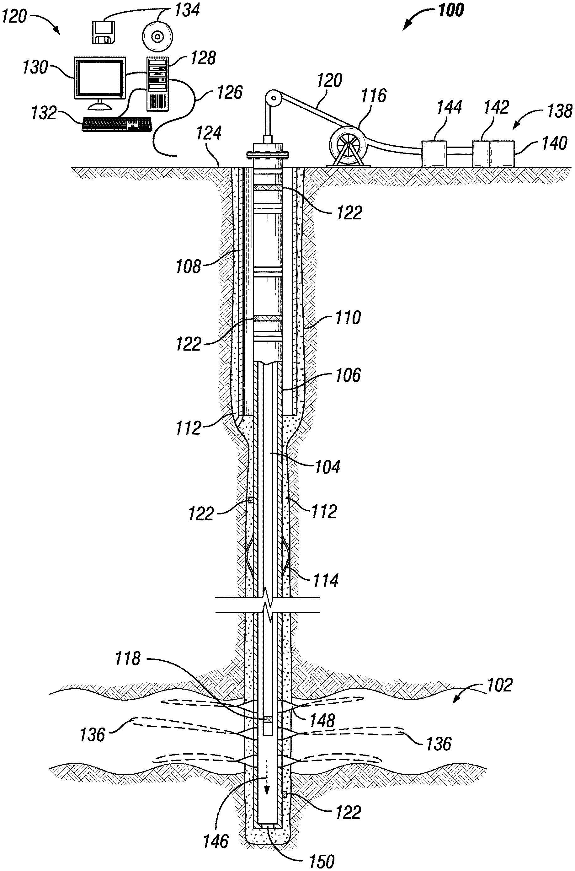
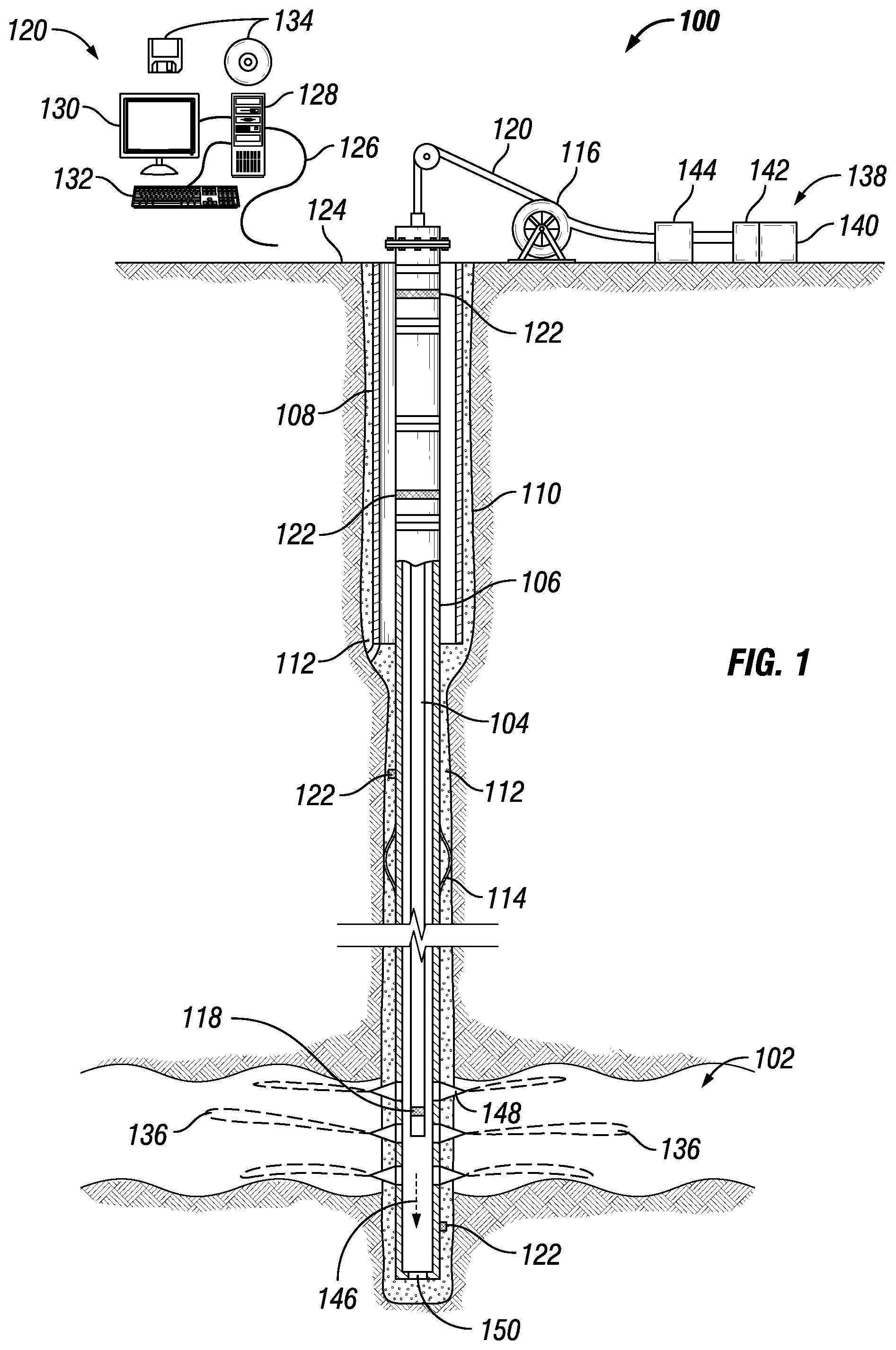
[0008] FIG. 1 illustrates an example well system 100 for use with a subterranean well. In the illustrated embodiment, well system 100 may be used to stimulate a formation 102 (e.g., fracking, acid matrix stimulation, etc.) through coil tubing 104. In examples, coil tubing 104 may be disposed within conduits (e.g., first casing 106, second casing 108, etc.) The conduits may comprise a suitable material, such as steel, chromium, or alloys. As illustrated, a wellbore 110 may extend through formation 102 and/or a plurality of formations 102. While wellbore 110 is shown extending generally vertically into formation 102, the principles described herein are also applicable to wellbores that extend at an angle through formation 102, such as horizontal and slanted wellbores. For example, although FIG. 1 shows a vertical or low inclination angle well, high inclination angle or horizontal placement of the well and equipment is also possible. It should further be noted that while FIG. 1 generally depicts a land-based operation, those skilled in the art will readily recognize that the principles described herein are equally applicable to subsea operations that employ floating or sea-based platforms and rigs, without departing from the scope of the disclosure.
[0009] As illustrated on FIG. 1, one or more conduits, shown here as first casing 106 and second casing 108 may be disposed in the wellbore 110. First casing 106 may be in the form of an intermediate casing, a production casing, a liner, or other suitable conduit, as will be appreciated by those of ordinary skill in the art. Second casing 108 may be in the form of a surface casing, intermediate casing, or other suitable conduit, as will be appreciated by those of ordinary skill in the art. While not illustrated, additional conduits may also be installed in the wellbore 110 as desired for a particular application. In the illustrated embodiment, first casing 106 and the second casing 108 may be cemented to the walls of wellbore 110 by cement 112. Without limitation, one or more centralizers 114 may be attached to either first casing 106 and/or the second casing 108, for example, to centralize the respective conduit in wellbore 110, as well as protect additional equipment (e.g., electromagnetic field sensors, not illustrated).
[0010] In the illustrated embodiment, well system 100 may comprise a hoist 116 and a transciever 118. Without limitation, transciever 118 may be disposed about the end of coil tubing 104. In examples, coil tubing 104 may be spooled within hoist 116. In examples, hoist 116 may be used to raise and/or lower coil tubing 104, which may comprise transciever 118, in wellbore 110. Hoist 116 may attach to transciever 118 through coil tubing 104. Coil tubing 104 may be any suitable tubing that may support transciever 118. Coil tubing 104 may also deliver fluids, proppants, and/or the like downhole to formation 102. As discussed below, there may be additional tools that may be disposed on coil tubing 104.
[0011] Well system 100 may further comprise an information handling system 120. Information handling system 100 may be in signal communication with the transceiver 118. Without limitation, signals from transceiver 118 may be transmitted through secondary transceivers 122a-122d which may be disposed on first casing 106. As discussed below, transceiver 118 and secondary transceivers 122a-122d may operate to pass information and/or measurements to information handling system 120. As illustrated, information handling system 120 may be disposed at surface 124. In examples, information handling system 120 may be disposed downhole. Any suitable technique may be used for transmitting signals from coil tubing 104 to information handling system 120. As illustrated, a communication link 126 (which may be wired or wireless, for example) may be provided that may transmit data from secondary transceivers 122a-122d to information handling system 120. Without limitation in this disclosure, information handling system 120 may include any instrumentality or aggregate of instrumentalities operable to compute, classify, process, transmit, receive, retrieve, originate, switch, store, display, manifest, detect, record, reproduce, handle, or utilize any form of information, intelligence, or data for business, scientific, control, or other purposes. For example, information handling system 120 may be a personal computer, a network storage device, or any other suitable device and may vary in size, shape, performance, functionality, and price. Information handling system 120 may include random access memory (RAM), one or more processing resources (e.g. a microprocessor) such as a central processing unit 128 (CPU) or hardware or software control logic, ROM, and/or other types of nonvolatile memory. Additional components of information handling system 120 may include one or more of a monitor 130, an input device 132 (e.g., keyboard, mouse, etc.) as well as computer media 134 (e.g., optical disks, magnetic disks) that may store code representative of the above-described methods. Information handling system 120 may also include one or more buses (not shown) operable to transmit communications between the various hardware components. Information handling system 120 may be adapted to receive signals from transceiver 118 that may be representative of measurements from a tool disposed on coil tubing 104. Information handling system 120 may act as a data acquisition system and possibly a data processing system that analyzes measurements, for example, to derive one or more properties of formation 102, measurements and/or information from tool, and/or analyzing measurements on work performed by well system 100.
[0012] As mentioned above transceiver 118 may be disposed about an end of coil tubing 104 opposite surface 124, as illustrated in FIG. 1. In examples, transceiver 118 may be disposed at any suitable location along coil tubing 104. An additional examples, there may be any number of transceivers 118 disposed at an end of coil tubing 104 opposite surface 124 which may communicate with each other before communicating with secondary transceivers 122a-122d or communicate separately to secondary transceivers 122a-122d. Transceiver 118 may communicate (e.g., wirelessly) with tools, not illustrated, that may be attached to coil tubing 104 and/or wellbore 110. Furthermore, transceiver 118 may comprise sensors that may take measurements and/or record information. Information and/or measurements recorded and/or stored on transceiver 118 may be performed by an information handling system 120 disposed within transceiver 118, not illustrated. As transceiver 118 traverses down wellbore 110, transceiver 118 may communicate with secondary transceivers 122a-122d, which may be disposed on first casing 106 and/or second casing 108. During operations, transceiver 118 may wirelessly transmit information and/or recorded measurements to a secondary transceivers 122a-122d which may be closest to transceiver 118. As coil tubing 104 traverses wellbore 110, transceiver 118 may communicate with different secondary transceivers 122a-122d as a second secondary transceiver 122b comes closer to transceiver 118 than a first secondary transceiver 122a. In examples, transceiver 118 may have physical contact with the tubing wall adjacent to coil tubing 104 (e.g. first casing 106). This may be accomplished through one and/or more centralizer, decentralizer, and/or relying on the inherent eccentricity of running coil tubing 106 to create an acoustic pathway. Passing information, measurements, and/or recordings to secondary transceivers 122a-122d from transceiver 118, the information measurements, and/or recordings may be transmitted through a chain of secondary transceivers 122a-122d to information handling system 120, which may be disposed on surface 124.
[0013] Secondary transceivers 122a-122d may communicate with each other wirelessly through acoustic energy to bring information, measurements, and/or recordings to information handling system 120 disposed on surface 124. Specifically, secondary transceivers 122a-122d may utilize acoustic energy through a medium they may be disposed on to communicate information, measurements, and/or recordings from transceiver 118. For example, a first secondary transceiver 122a, which may be disposed on first casing 106 may broadcast acoustic energy through first casing 106 to second secondary transceiver 122b which may be disposed closer to surface 124 than first secondary transceiver 122a. The acoustic energy may comprise information, measurements, and/or recordings from transceiver 118. Second secondary transceiver 122b may capture then acoustic energy and re-broadcast the acoustic energy to a third secondary transceiver 122c. This process may be repeated any number of times until the information and measurements transmitted from transceiver 118 may be recorded by a final secondary transceiver 122d, which may be attached to information handling system 120 through communication link 126. It should be noted that coil tubing 104 may be pulled up toward surface 124 by hoist 116 before transmitting information and/or measurements between transceiver 118 and secondary transceiver 122a-122d. This may increase communication flow during Production Logging Testing (PLT) and may reduce communication interference. Which may be prevalent in offshore environments, wherein abrasion between coil tubing 104, tool, and first casing 106 may occur to do marine heave, which may hinder communication.
[0014] Well system 100 comprising transceiver 118 and at least one secondary transceiver 122a-122d may allow an operator to wirelessly collect PLT (Production Logging Testing) data from wellbore 110 while wellbore 110 may be stimulated with coil tubing 104. This may allow an operator to evaluate the success of stimulation work in well system 100 in real time without removing coil tubing 106 from wellbore 110, which may be expensive and time consuming. Wireless data collection may be performed numerous times in a single operation and may be run in tandem with other systems (not illustrated) in wellbore 110. Obtaining production data and/or downhole samples in real-time from a flowing well while coil tubing 104 is disposed in wellbore 110 may allow for a faster, cheaper, and better understanding of formation 102. Utilizing transceiver 118 and secondary transceivers 122a-122d, may allow for real time two-way data transmission from an end of coil tubing 104 opposite surface 124. This may allow for two-way communication with any combination of tools such as PLT, samplers, gauges, plugs, shut-in tools, and/or the like. Two-way communication may be useful during stimulation operations within wellbore 110, for example, during a stimulation operation comprising fracking.
[0015] FIG. 1 further illustrate well system 100 operation to introduce a fluid into fractures 136. Well system 100 may include a fluid handling system 138, which may include fluid supply 140, mixing equipment 142, and pumping equipment 144 which may be connected to coil tubing 104. Pumping equipment 144 may be fluidly coupled with the fluid supply 140 and coil tubing 104 to communicate a fracturing fluid 146 into wellbore 110. Fluid supply 140 and pumping equipment 144 may be above surface 124 while wellbore 110 is below surface 124.
[0016] Well system 100 may also be used for the injection of a pad or pre-pad fluid into formation 102 at an injection rate above the fracture gradient to create at least one fracture 136 in formation 100. Well system 100 may then inject fracturing fluid 146 into formation 102 surrounding wellbore 110 through perforation 148. Perforations 148 may allow communication between wellbore 110 and formation 102. As illustrated, perforations 148 may penetrate first casing 106 and cement 112 allowing communication between interior of first casing 106 and fractures 136. A plug 150, which may be any type of plug for oilfield applications (e.g., bridge plug), may be disposed in wellbore 110 below perforations 148.
[0017] In accordance with systems, methods, and/or compositions of the present disclosure, fracturing fluid 146 may be pumped via pumping equipment 144 from fluid supply 140 down the interior of first casing 106 through coil tubing 104 and into formation 102 at or above a fracture gradient of formation 102. Pumping fracturing fluid 146 at or above the fracture gradient of formation 102 may create (or enhance) at least one fracture (e.g., fractures 136) extending from the perforations 148 into formation 102. During fracking operations, transceiver 118 may record information and measurements regarding the progression of the fracking operations. Recorded information and measurements may be communicated to an operator on the surface from transceiver 118 through secondary transceivers 122 as detailed above.
[0018] FIG. 2 illustrates an example in which a downhole tool 200 may be disposed at the end of coil tubing 104. In examples, downhole tool 200 may be any type of tool that may be utilized with coil tubing 104. For example, tools may be utilized with coil tubing 104 to stimulate wellbore 110 prior to flowing wellbore 110 during a Drill String Test (DST). Downhole tool 200 disposed at an end of coil tubing 104 opposite surface 124 may be beneficial if paired with transceiver 118. This may allow for data and/or samples to be read in real-time and/or about real-time from a flowing well while coil tubing 104 may be disposed in wellbore 110 during a DST. Currently, it is necessary to pull coil tubing 104 out of wellbore 110 and use a wireline to obtain this data. A transceiver 118 communicating with secondary transceivers 122a-122d may form a real-time two-way data transmission from downhole tool 200. In examples, downhole tool 200 may comprise samplers, gauges, plugs, shut-in tools, and/or the like. It should be noted that multiple downhole tools 200 may be paired with individual transceiver 118 and/or a shared transceiver 118. This may allow an operator on the surface to control and/or receiver information from any number of downhole tools 200. As stated above, transceiver 118 may communicate to the surface through secondary transceivers 122a-122d.
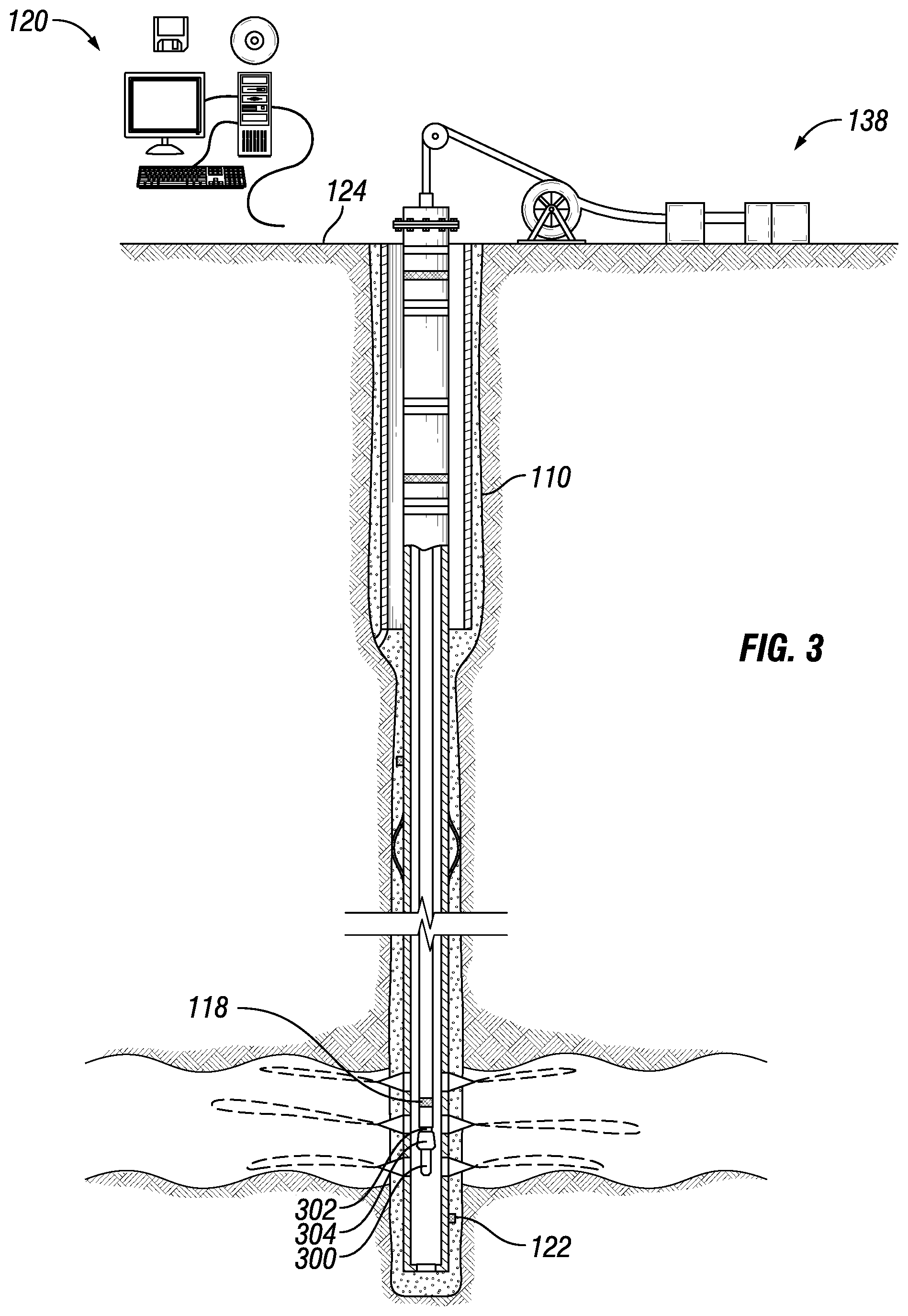
[0019] FIG. 3 illustrate an example in which a sampler 300 may be disposed at an end of coil tubing 104 opposite surface 124. As discussed above, sampler 300 may be disposed at the end of coil tubing 104 during a DST. During a DST it may be desirable to take single-phase fluid samples.
[0020] Sampler 300 may be provided by a battery, by a mud turbine, or through a wired pipe from the surface, or through some other conventional means. In a wireline or slickline environment, power may be provided by a battery or by power provided from the surface through the wired drill pipe, wireline, coil tubing, or slickline, or through some other conventional means.
[0021] Sampler 300 may include transceiver 118, through which sampler 300 communicate with other actuators and sensors disposed on coil tubing 104 and/or secondary transceivers 122a-122d. In examples, transceiver 118 may also be the port through which the various actuators (e.g. valves) and sensors (e.g., temperature and pressure sensors) in sampler 300 may be controlled and monitored. As discussed above, transceiver 118 may include information handling system 120 that may exercise control and monitoring functions. The control and monitoring functions may be performed by information handling system 120 in another part of coil tubing 104 (not shown) or by information handling system 102 disposed on surface 124.
[0022] Sampler 300 may include a formation probe section, which may extract fluid from wellbore 110, as described in more detail below, and may deliver it to a channel (not illustrated) that may extend from one end of sampler 300 to the other. The channel may be connected to other downhole tools. Sampler 300 may also include a quartz gauge section (not illustrated), which may include sensors to allow measurement of properties, such as temperature and pressure, of the fluid in the channel. Sampler 300 may include a flow-control pump-out section (not illustrated), which may include a high-volume bidirectional pump (not illustrated) for pumping fluid through the channel. Sampler 300 may include at least one sample chamber sections (not illustrated) for testing fluid in wellbore 110.
[0023] Currently, sampling fluid may be performed by a wireline in which a triggering mechanism 304 and sampler 300 are attached to the wireline (not illustrated). In examples, information handling system 120 may send a command through secondary transceivers 122a-122d to transceiver 118, which may be connected to triggering mechanism 304. For example, a command may be to activate sampler 300. Triggering mechanism may 304 activate sampler 300 through a timing mechanism and/or acoustic telemetry. As disclosed, sampler 300 may attach to coil tubing 104 through knuckle joint 302. Transceiver 118 may be disposed on sampler 300 and/or communicate with sampler 300 from coil tubing 104. Such communication may be performed wirelessly and/or through a hard connection, such as wires. This may allow samples to be taken by sampler 300 during a DST, stimulation, cleanup, and/or an acidizing and nitrogen lift. Information and/or measurements taken by sampler 300 may be stored in information handling system 120, which may be disposed downhole with transceiver 118. In examples, transceiver may transmit the recorded information and/or measurements to surface 124 through secondary transceivers 122a-122d, as discussed above. As discussed above, a two-way communication may be formed utilizing a transceiver 118 and secondary transceivers 122a-122d. This may allow an operator to activate sampler 300 at any desirable location within wellbore 110.
[0024] This method and system may include any of the various features of the compositions, methods, and system disclosed herein, including one or more of the following statements.
[0025] Statement 1: A well system comprising a coil tubing: a transceiver, wherein the transceiver is disposed about an end of the coil tubing opposite a surface; a secondary transceiver, wherein the secondary transceiver is disposed on a casing; and an information handling system, wherein the information handling system is configured to record information from the transceiver.
[0026] Statement 2: The well system of statement 1, wherein the transceiver further comprise a sensor, wherein the sensor configured to take measurements in a wellbore.
[0027] Statement 3: The well system of statement 1 or statement 2, wherein a downhole tool is disposed at the end of the coil tubing opposite the surface.
[0028] Statement 4: The well system of any previous statement, wherein the transceiver is disposed on the downhole tool.
[0029] Statement 5: The well system of any previous statement, wherein the transceiver is operable to communicate with the secondary transceiver wirelessly.
[0030] Statement 6: The well system of any previous statement, wherein the transceiver is operable to communicate with the secondary transceiver through an acoustic pathway.
[0031] Statement 7: The well system of any previous statement, further comprising a downhole tool, wherein the downhole tool is a sampler, gauge, plug, shut-in tool, or triggering mechanism.
[0032] Statement 8: The well system of any previous statement, further comprising a knuckle joint, a trigger, and a sampler.
[0033] Statement 9: The well system of any previous statement, wherein the transceiver is disposed on the trigger.
[0034] Statement 10: The well system of any previous statement, further comprising a plurality of transceivers disposed on the coil tubing and a plurality of secondary transceivers disposed on the casing.
[0035] Statement 11: A method for wirelessly communicating in a wellbore comprising: disposing a coil tubing into the wellbore, wherein a transceiver is disposed about an end of the coil tubing opposite a surface; recording a measurement with the transceiver, wherein the transceiver comprises a sensor; communicating the measurement from the transceiver to a secondary transceiver; transmitting the measurement from the secondary transceiver to one or more additional secondary transceivers; and retrieving the measurement from the one or more additional secondary transceivers by an information handling system.
[0036] Statement 12: The method of statement 11, wherein the communicating the measurement from the transceiver to a secondary transceiver is performed wirelessly.
[0037] Statement 13: The method of statement 11 or statement 12, wherein the communicating the measurement from the transceiver to a secondary transceiver is performed through an acoustic pathway.
[0038] Statement 14: The method of statement 11-statement 13, further comprising pulling up the coil tubing with the hoist to transmit the measurement.
[0039] Statement 15: The method of statement 11-statement 14, wherein a triggering mechanism and a sampler are connected to the coil tubing through a knuckle joint.
[0040] Statement 16: The method of statement 11-statement 15, further comprising transmitting a command from the information handling system to the triggering mechanism and triggering the sampler.
[0041] Statement 17: The method of statement 11-statement 16, wherein the communicating the measurement is performed real time during a drill string test.
[0042] Statement 18: The method of statement 11-statement 17, wherein the communicating the measurement is performed real time during a production logging test.
[0043] Statement 19: The method of statement 11-statement 18, further comprising attaching a downhole tool to the coil tubing.
[0044] Statement 20: The method of statement 11-statement 19, wherein the transceiver is disposed on the downhole tool.
[0045] The preceding description provides various embodiments of the systems and methods of use disclosed herein which may contain different method steps and alternative combinations of components. It should be understood that, although individual embodiments may be discussed herein, the present disclosure covers all combinations of the disclosed embodiments, including, without limitation, the different component combinations, method step combinations, and properties of the system. It should be understood that the compositions and methods are described in terms of "comprising," "containing," or "including" various components or steps, the compositions and methods can also "consist essentially of" or "consist of" the various components and steps. Moreover, the indefinite articles "a" or "an," as used in the claims, are defined herein to mean one or more than one of the element that it introduces.
[0046] For the sake of brevity, only certain ranges are explicitly disclosed herein. However, ranges from any lower limit may be combined with any upper limit to recite a range not explicitly recited, as well as, ranges from any lower limit may be combined with any other lower limit to recite a range not explicitly recited, in the same way, ranges from any upper limit may be combined with any other upper limit to recite a range not explicitly recited. Additionally, whenever a numerical range with a lower limit and an upper limit is disclosed, any number and any included range falling within the range are specifically disclosed. In particular, every range of values (of the form, "from about a to about b," or, equivalently, "from approximately a to b," or, equivalently, "from approximately a-b") disclosed herein is to be understood to set forth every number and range encompassed within the broader range of values even if not explicitly recited. Thus, every point or individual value may serve as its own lower or upper limit combined with any other point or individual value or any other lower or upper limit, to recite a range not explicitly recited.
[0047] Therefore, the present embodiments are well adapted to attain the ends and advantages mentioned as well as those that are inherent therein. The particular embodiments disclosed above are illustrative only, and may be modified and practiced in different but equivalent manners apparent to those skilled in the art having the benefit of the teachings herein. Although individual embodiments are discussed, the disclosure covers all combinations of all of the embodiments. Furthermore, no limitations are intended to the details of construction or design herein shown, other than as described in the claims below. Also, the terms in the claims have their plain, ordinary meaning unless otherwise explicitly and clearly defined by the patentee. It is therefore evident that the particular illustrative embodiments disclosed above may be altered or modified and all such variations are considered within the scope and spirit of those embodiments. If there is any conflict in the usages of a word or term in this specification and one or more patent(s) or other documents that may be incorporated herein by reference, the definitions that are consistent with this specification should be adopted.
* * * * *
D00000
D00001
D00002
D00003
XML
uspto.report is an independent third-party trademark research tool that is not affiliated, endorsed, or sponsored by the United States Patent and Trademark Office (USPTO) or any other governmental organization. The information provided by uspto.report is based on publicly available data at the time of writing and is intended for informational purposes only.
While we strive to provide accurate and up-to-date information, we do not guarantee the accuracy, completeness, reliability, or suitability of the information displayed on this site. The use of this site is at your own risk. Any reliance you place on such information is therefore strictly at your own risk.
All official trademark data, including owner information, should be verified by visiting the official USPTO website at www.uspto.gov. This site is not intended to replace professional legal advice and should not be used as a substitute for consulting with a legal professional who is knowledgeable about trademark law.