High Power Laser Hydraulic Fracturing, Stimulation, Tools Systems And Methods
Deutch; Paul D. ; et al.
U.S. patent application number 16/786600 was filed with the patent office on 2020-07-23 for high power laser hydraulic fracturing, stimulation, tools systems and methods. This patent application is currently assigned to Foro Energy, Inc.. The applicant listed for this patent is Foro Energy, Inc.. Invention is credited to Ronald A. De Witt, Paul D. Deutch, John Ely, Brian O. Faircloth, Fred C. Kellermann, John Yearwood, Mark S. Zediker, Tom Zimmerman.
| Application Number | 20200232309 16/786600 |
| Document ID | / |
| Family ID | 50731830 |
| Filed Date | 2020-07-23 |


View All Diagrams
| United States Patent Application | 20200232309 |
| Kind Code | A1 |
| Deutch; Paul D. ; et al. | July 23, 2020 |
HIGH POWER LASER HYDRAULIC FRACTURING, STIMULATION, TOOLS SYSTEMS AND METHODS
Abstract
There are provided high power laser perforation, hydraulic fracturing systems, tools and methods for the stimulation and recovery of energy sources, such as hydrocarbons, from a formation. These systems, tools and methods provide predetermined laser beam energy patterns, to provide for the down hole volumetric removal of custom geometries of materials, sealing of perforations, reperorations, refractures and other downhole actives.
| Inventors: | Deutch; Paul D.; (Houston, TX) ; Kellermann; Fred C.; (Sugar Land, TX) ; Zimmerman; Tom; (Pearland, TX) ; Yearwood; John; (Houston, TX) ; Zediker; Mark S.; (Castle Rock, CO) ; De Witt; Ronald A.; (Katy, TX) ; Faircloth; Brian O.; (Evergreen, CO) ; Ely; John; (Montgomery, TX) | ||||||||||
| Applicant: |
|
||||||||||
|---|---|---|---|---|---|---|---|---|---|---|---|
| Assignee: | Foro Energy, Inc. Houston TX |
||||||||||
| Family ID: | 50731830 | ||||||||||
| Appl. No.: | 16/786600 | ||||||||||
| Filed: | February 10, 2020 |
Related U.S. Patent Documents
| Application Number | Filing Date | Patent Number | ||
|---|---|---|---|---|
| 16058546 | Aug 8, 2018 | |||
| 16786600 | ||||
| 14082026 | Nov 15, 2013 | 10053967 | ||
| 16058546 | ||||
| 13782869 | Mar 1, 2013 | 9719302 | ||
| 14082026 | ||||
| 13222931 | Aug 31, 2011 | |||
| 13782869 | ||||
| 13210581 | Aug 16, 2011 | 8662160 | ||
| 14082026 | ||||
| 12543986 | Aug 19, 2009 | 8826973 | ||
| 13210581 | ||||
| 61727096 | Nov 15, 2012 | |||
| 61786687 | Mar 15, 2013 | |||
| 61378910 | Aug 31, 2010 | |||
| 61090384 | Aug 20, 2008 | |||
| 61102730 | Oct 3, 2008 | |||
| 61106472 | Oct 17, 2008 | |||
| 61153271 | Feb 17, 2009 | |||
| 61798875 | Mar 15, 2013 | |||
| Current U.S. Class: | 1/1 |
| Current CPC Class: | E21B 43/11 20130101; E21B 43/119 20130101; E21B 43/26 20130101 |
| International Class: | E21B 43/26 20060101 E21B043/26; E21B 43/119 20060101 E21B043/119; E21B 43/11 20060101 E21B043/11 |
Claims
1.-29. (canceled)
30. A method of stimulating a well, the method comprising: positioning a laser perforating tool in the borehole at a location in a formation; delivering a plurality of high power laser beams, each comprising 10 kW of power, in a plurality of predetermined laser beam patterns; the laser beam patterns position at the location and extending along a length of the borehole, wherein the position of the laser beam patterns is based at least in part upon a stress plane in the formation; whereby each laser beam creates a discrete volumetric removal having a predetermined shape defining a laser perforation; and, flowing a fracturing fluid under pressure down the borehole, through the laser perforation and into the formation, whereby the formation is hydraulically fractured.
31. The method of claim 30, wherein the shape of the laser beam patterns is predetermined at least in part to reduce near borehole tortuosity.
32. (canceled)
33. (canceled)
34. The method of claim 30, wherein the shape of the laser beam patterns is at least in part reduces near borehole tortuosity.
35. (canceled)
36. The method of claim 30, wherein the shape of the laser beam patterns is at least in part essentially eliminates near borehole tortuosity.
37. The method of claim 30, wherein the position of the laser beam patterns at least in part essentially eliminates near borehole tortuosity.
38. (canceled)
39. (canceled)
40. (canceled)
41. (canceled)
42. (canceled)
43. (canceled)
44. (canceled)
45. (canceled)
46. The method of claim 32, wherein the location along the borehole comprises about 5,000 feet of measured depth and the laser beam comprises of 10 kW of power.
47. (canceled)
48. (canceled)
49. (canceled)
50. (canceled)
51. (canceled)
52. (canceled)
53. (canceled)
54. (canceled)
55. (canceled)
56. (canceled)
57. (canceled)
58. (canceled)
59. (canceled)
60. (canceled)
61. (canceled)
62. (canceled)
63. (canceled)
64. (canceled)
65. (canceled)
66. A method of stimulating a well, the method comprising: positioning a laser beam delivery head in the borehole at a location in a formation, the location being at a measured depth comprising of 5,000 ft; delivering a plurality of high power laser beams, each comprising 10 kW of power, in a plurality of predetermined laser beam patterns; the laser beam patterns positioned at the location and extending along a length of the borehole, wherein the position of the laser beam patterns is based at least in part upon a stress plane in the formation; whereby each laser beam creates a discrete volumetric removal having a predetermined shape defining a laser perforation; and, flowing a fracturing fluid under pressure down the borehole, through the laser perforation and into the formation, whereby the formation is hydraulically fractured.
67. The method of claim 66, wherein the stress plane is a preferred stress plane.
68. The method of claim 66, wherein the identified stress comprises a preferred stress plane and at least one volumetric removal follows the preferred stress plane.
69. (canceled)
70. (canceled)
71. (canceled)
72. The method of claim 66, wherein at least one volumetric removal follows the stress plane.
73. (canceled)
74. The method of claim 66, wherein at least one volumetric removal is positioned in and parallel with the preferred stress plane.
75. (canceled)
76. The method of claim 66, wherein the fracturing fluid is slick water.
77. (canceled)
78. (canceled)
79. (canceled)
80. (canceled)
81. (canceled)
82. (canceled)
83. (canceled)
84. (canceled)
85. (canceled)
86. (canceled)
87. (canceled)
88. (canceled)
89. (canceled)
90. (canceled)
91. (canceled)
92. (canceled)
93. (canceled)
94. (canceled)
95. (canceled)
96. (canceled)
97. (canceled)
98. (canceled)
99. (canceled)
100. (canceled)
101. (canceled)
102. (canceled)
103. (canceled)
104. (canceled)
105. (canceled)
106. (canceled)
107. (canceled)
108. (canceled)
109. (canceled)
110. (canceled)
111. (canceled)
112. (canceled)
113. (canceled)
114. (canceled)
115. The method of claim 66, wherein at least of one of volumetric removal is in the shape of a rectangular slot.
116. The method of claim 66, wherein the volumetric removals are each in the shape of a rectangular slot.
117-179 (canceled)
180. A method of laser hydraulic fracturing a well, the method comprising: positioning a laser perforating tool in the borehole at a location in a formation; delivering a plurality of high power laser beams each comprising 10 kW of power in a plurality of predetermined laser beam patterns, the laser beam patterns position at the location and extending along a length of the borehole, wherein the position of the laser beam patterns is based at least in part upon a stress plane in the formation; whereby each laser beam creates a discrete volumetric removal having a predetermined shape defining a laser perforation; and, flowing a fracturing fluid under pressure down the borehole, through the laser perforation and into the formation, whereby the formation is hydraulically fractured.
181. The method of claim 180, wherein each laser perforation defines an opening in a casing in the borehole, wherein each opening is a circle, and wherein the diameters of each opening vary by no more than 2%.
182. The method of claim 180, wherein each laser perforation defines an opening in a casing in the borehole comprising an opening edge, wherein each opening is a circle, and wherein each opening edge is essentially burr free.
183. The method of claim 180, wherein each laser perforation defines an opening in a casing in the borehole comprising an opening edge, wherein each opening is a circle, and wherein each opening edge is essentially smooth.
184. (canceled)
185. (canceled)
186. (canceled)
187. (canceled)
188. (canceled)
189. (canceled)
190. (canceled)
191. (canceled)
192. A method of stimulating a well, the method comprising: positioning a laser hydraulic fracturing assembly in the borehole at a location in a formation; delivering a plurality of high power laser beams, each having not less than 10 kW of power, in a plurality of predetermined laser beam patterns; the laser beam patterns positioned at the location and extending along a length of the borehole, wherein the position of the laser beam patterns is based at least in part upon a stress plane in the formation; wherein the shape of the laser beam patterns is predetermined at least in part to reduce near borehole tortuosity; and, whereby each laser beam creates a discrete volumetric removal having a predetermined shape defining a laser perforation.
193-222. (canceled)
Description
[0001] This application: (i) claims, under 35 U.S.C. .sctn. 119(e)(1), the benefit of the filing date of Nov. 15, 2012 of provisional application Ser. No. 61/727,096; (ii) claims, under 35 U.S.C. .sctn. 119(e)(1), the benefit of the filing date of Mar. 15, 2013 of provisional application Ser. No. 61/786,687; (iii) is a continuation-in-part of U.S. patent application Ser. No. 13/782,869, filed Mar. 1, 2013; (iv) is a continuation-in-part of U.S. patent application Ser. No. 13/222,931, filed Aug. 31, 2011, which claims, under 35 U.S.C. .sctn. 119(e)(1), the benefit of the filing date of Aug. 31, 2010 of provisional application Ser. No. 61/378,910 and the benefit of the filing date of Aug. 20, 2008 of provisional application Ser. No. 61/090,384; (v) is a continuation-in-part of Ser. No. 13/210,581; (vi) is a continuation-in-part of Ser. No. 12/543,986, filed Aug. 19, 2009, which claims, under 35 U.S.C. .sctn. 119(e)(1), the benefit of the filing date of Aug. 20, 2008 of provisional application Ser. No. 61/090,384, the benefit of the filing date of Oct. 3, 2008 of provisional application Ser. No. 61/102,730, the benefit of the filing date of Oct. 17, 2008 of provisional application Ser. No. 61/106,472, and the benefit of the filing date of Feb. 17, 2009 of provisional application Ser. No. 61/153,271; and (vii) claims, under 35 U.S.C. .sctn. 119(e)(1), the benefit of the filing date of Mar. 15, 2013 of provisional application Ser. No. 61/798,875, the entire disclosures of each of which are incorporated herein by reference.
BACKGROUND OF THE INVENTION
Field of the Invention
[0002] The present inventions relate to hydraulic fracturing, well stimulation and the recovery of energy sources using high power laser tools. In particular, the present inventions relate to hydrocarbon and energy recovery through high power laser hydraulic fracturing, perforating, fracturing, and opening, increasing and enhancing the flow of energy sources, from a formation or reservoir into a production tubing or collection system. In addition to improved performance and safety over conventional systems, such as explosive based perforating guns and high pressure jetting with solids laden fluids, the present inventions provide for the precise and predetermined placement of laser beam energy, in precise and predetermined energy distribution patterns, e.g., custom geometries, custom perforations, custom fracture patterns, volumetric removals and laser adaptive fracturing. These custom operations can be tailored and fitted to the particular geological and structural features of a formation, reservoir and pay zone. Unlike conventional methods, such as explosive perforating tools and high pressure jetting with solids laden fluids, the laser beam and laser process can be controlled or operated in a manner that provides numerous advantages, such as for example, increase control, custom volumetric removals and geometries, adaptive volumetric removals and geometries, maintaining and enhancing the porosity, openness and structure of the inner surface of the openings.
[0003] As used herein, unless specified otherwise "high power laser energy" means a laser beam having at least about 1 kW (kilowatt) of power. As used herein, unless specified otherwise "great distances" means at least about 500 m (meter). As used herein, unless specified otherwise, the term "substantial loss of power," "substantial power loss" and similar such phrases, mean a loss of power of more than about 3.0 dB/km (decibel/kilometer) for a selected wavelength. As used herein the term "substantial power transmission" means at least about 50% transmittance.
[0004] As used herein, unless specified otherwise, "optical connector", "fiber optics connector", "connector" and similar terms should be given their broadest possible meanings and include any component from which a laser beam is or can be propagated, any component into which a laser beam can be propagated, and any component that propagates, receives or both a laser beam in relation to, e.g., free space, (which would include a vacuum, a gas, a liquid, a foam and other non-optical component materials), an optical component, a wave guide, a fiber, and combinations of the forgoing.
[0005] As used herein, unless specified otherwise, the term "earth" should be given its broadest possible meaning, and includes, the ground, all natural materials, such as rocks, and artificial materials, such as concrete, that are or may be found in the ground, including without limitation rock layer formations, such as, granite, basalt, sandstone, dolomite, sand, salt, limestone, rhyolite, quartzite and shale rock.
[0006] As used herein, unless specified otherwise, the term "borehole" should be given it broadest possible meaning and includes any opening that is created in a material, a work piece, a surface, the earth, a structure (e.g., building, protected military installation, nuclear plant, offshore platform, or ship), or in a structure in the ground, (e.g., foundation, roadway, airstrip, cave or subterranean structure) that is substantially longer than it is wide, such as a well, a well bore, a well hole, a micro hole, slimhole and other terms commonly used or known in the arts to define these types of narrow long passages. Wells would further include exploratory, production, abandoned, reentered, reworked, and injection wells, and cased and uncased or open holes. Although boreholes are generally oriented substantially vertically, they may also be oriented on an angle from vertical, to and including horizontal. Thus, using a vertical line, based upon a level as a reference point, a borehole can have orientations ranging from 0.degree. i.e., vertical, to 90.degree., i.e., horizontal and greater than 90.degree. e.g., such as a heel and toe, and combinations of these such as for example "U" and "Y" shapes; there may also be for example multilateral boreholes in a fishbone pattern, and multilateral horizontal boreholes initiated at different levels in the earth from the mother bore. Boreholes may further have segments or sections that have different orientations, they may have straight sections and arcuate sections and combinations thereof; and for example may be of the shapes commonly found when directional drilling is employed. Thus, as used herein unless expressly provided otherwise, the "bottom" of a borehole, the "bottom surface" of the borehole and similar terms refer to the end of the borehole, i.e., that portion of the borehole furthest along the path of the borehole from the borehole's opening, the surface of the earth, or the borehole's beginning. The terms "side" and "wall" of a borehole should to be given their broadest possible meaning and include the longitudinal surfaces of the borehole, whether or not casing or a liner is present, as such, these terms would include the sides of an open borehole or the sides of the casing that has been positioned within a borehole. Boreholes may be made up of a single passage, multiple passages, connected passages and combinations thereof, in a situation where multiple boreholes are connected or interconnected each borehole would have a borehole bottom. Boreholes may be formed in the sea floor, under bodies of water, on land, in ice formations, or in other locations and settings.
[0007] Boreholes are generally formed and advanced by using mechanical drilling equipment having a rotating drilling tool, e.g., a bit. For example and in general, when creating a borehole in the earth, a drilling bit is extending to and into the earth and rotated to create a hole in the earth. In general, to perform the drilling operation the bit must be forced against the material to be removed with a sufficient force to exceed the shear strength, compressive strength or combinations thereof, of that material. Thus, in conventional drilling activity mechanical forces exceeding these strengths of the rock or earth must be applied. The material that is cut from the earth is generally known as cuttings, e.g., waste, which may be chips of rock, dust, rock fibers and other types of materials and structures that may be created by the bit's interactions with the earth. These cuttings are typically removed from the borehole by the use of fluids, which fluids can be liquids, foams or gases, or other materials know to the art.
[0008] As used herein, unless specified otherwise, the term "advancing" a borehole should be given its broadest possible meaning and includes increasing the length of the borehole. Thus, by advancing a borehole, provided the orientation is less than 90.degree. the depth of the borehole may also increased. The true vertical depth ("TVD") of a borehole is the distance from the top or surface of the borehole to the depth at which the bottom of the borehole is located, measured along a straight vertical line. The measured depth ("MD") of a borehole is the distance as measured along the actual path of the borehole from the top or surface to the bottom. As used herein unless specified otherwise the term depth of a borehole will refer to MD. In general, a point of reference may be used for the top of the borehole, such as the rotary table, drill floor, well head or initial opening or surface of the structure in which the borehole is placed.
[0009] As used herein, unless specified otherwise, the term "drill pipe" is to be given its broadest possible meaning and includes all forms of pipe used for drilling activities; and refers to a single section or piece of pipe. As used herein the terms "stand of drill pipe," "drill pipe stand," "stand of pipe," "stand" and similar type terms should be given their broadest possible meaning and include two, three or four sections of drill pipe that have been connected, e.g., joined together, typically by joints having threaded connections. As used herein the terms "drill string," "string," "string of drill pipe," string of pipe" and similar type terms should be given their broadest definition and would include a stand or stands joined together for the purpose of being employed in a borehole. Thus, a drill string could include many stands and many hundreds of sections of drill pipe.
[0010] As used herein, unless specified otherwise, the term "tubular" is to be given its broadest possible meaning and includes drill pipe, casing, riser, coiled tube, composite tube, vacuum insulated tubing ("VIT), production tubing and any similar structures having at least one channel therein that are, or could be used, in the drilling industry. As used herein the term "joint" is to be given its broadest possible meaning and includes all types of devices, systems, methods, structures and components used to connect tubulars together, such as for example, threaded pipe joints and bolted flanges. For drill pipe joints, the joint section typically has a thicker wall than the rest of the drill pipe. As used herein the thickness of the wall of tubular is the thickness of the material between the internal diameter of the tubular and the external diameter of the tubular.
[0011] As used herein, unless specified otherwise, the terms "blowout preventer," "BOP," and "BOP stack" should be given their broadest possible meanings, and include: (i) devices positioned at or near the borehole surface, e.g., the surface of the earth including dry land or the seafloor, which are used to contain or manage pressures or flows associated with a borehole; (ii) devices for containing or managing pressures or flows in a borehole that are associated with a subsea riser or a connector; (iii) devices having any number and combination of gates, valves or elastomeric packers for controlling or managing borehole pressures or flows; (iv) a subsea BOP stack, which stack could contain, for example, ram shears, pipe rams, blind rams and annular preventers; and, (v) other such similar combinations and assemblies of flow and pressure management devices to control borehole pressures, flows or both and, in particular, to control or manage emergency flow or pressure situations.
[0012] As used herein, unless specified otherwise, the terms "removal of material," "removing material," "remove" and similar such terms should be given their broadest possible meanings. Thus, such terms would include melting, flowing, vaporization, softening, laser induced break down, ablation; as well as, combinations and variations of these, and other processes and phenomena that can occur when directed energy from a laser beam is delivered to a material, object or work surface. Such terms would further include combinations of the forgoing laser induced processes and phenomena with the energy that the fluid jet imparts to the material to be cut. Moreover, irrespective of the processes or phenomena taking place, such terms would include the lessening, opening, cutting, severing or sectioning of the material, object or targeted structure.
[0013] As used herein, unless specified otherwise, the terms "workover," "completion" and "workover and completion" and similar such terms should be given their broadest possible meanings and would include activities that place at or near the completion of drilling a well, activities that take place at or the near the commencement of production from the well, activities that take place on the well when the well is a producing or operating well, activities that take place to reopen or reenter an abandoned or plugged well or branch of a well, and would also include for example, perforating, cementing, acidizing, fracturing, pressure testing, the removal of well debris, removal of plugs, insertion or replacement of production tubing, forming windows in casing to drill or complete lateral or branch wellbores, cutting and milling operations in general, insertion of screens, stimulating, cleaning, testing, analyzing and other such activities. These terms would further include applying heat, directed energy, preferably in the form of a high power laser beam to heat, melt, soften, activate, vaporize, disengage, desiccate and combinations and variations of these, materials in a well, or other structure, to remove, assist in their removal, cleanout, condition and combinations and variation of these, such materials.
[0014] As used herein, unless specified otherwise, the terms "conveyance structure", "umbilical", "line structure" and similar such terms should be given their broadest possible meanings and may be, contain or be optically or mechanically associated with: a single high power optical fiber; a single high power optical fiber that has shielding; a single high power optical fiber that has multiple layers of shielding; two, three or more high power optical fibers that are surrounded by a single protective layer, and each fiber may additionally have its own protective layer; a fiber support structure which may be integral with or releasable or fixedly attached to an optical fiber (e.g., a shielded optical fiber is clipped to the exterior of a metal cable and lowered by the cable into a borehole); other conduits such as a conduit to carry materials to assist a laser cutter, for example gas, air, nitrogen, oxygen, inert gases; other optical fibers or metal wires for the transmission of data and control information and signals; and any combinations and variations thereof.
[0015] The conveyance structure transmits high power laser energy from the laser to a location where high power laser energy is to be utilized or a high power laser activity is to be performed by, for example, a high power laser tool. The conveyance structure may, and preferably in some applications does, also serve as a conveyance device for the high power laser tool. The conveyance structure's design or configuration may range from a single optical fiber, to a simple to complex arrangement of fibers, support cables, shielding on other structures, depending upon such factors as the environmental conditions of use, performance requirements for the laser process, safety requirements, tool requirements both laser and non-laser support materials, tool function(s), power requirements, information and data gathering and transmitting requirements, control requirements, and combinations and variations of these.
[0016] Preferably, the conveyance structure may be coiled tubing, a tube within the coiled tubing, jointed drill pipe, jointed drill pipe having a pipe within a pipe, or may be any other type of line structure, that has a high power optical fiber associated with it. As used herein the term "line structure" should be given its broadest meaning, unless specifically stated otherwise, and would include without limitation: wireline; coiled tubing; slick line; logging cable; cable structures used for completion, workover, drilling, seismic, sensing, and logging; cable structures used for subsea completion and other subsea activities; umbilicals; cables structures used for scale removal, wax removal, pipe cleaning, casing cleaning, cleaning of other tubulars; cables used for ROV control power and data transmission; lines structures made from steel, wire and composite materials, such as carbon fiber, wire and mesh; line structures used for monitoring and evaluating pipeline and boreholes; and would include without limitation such structures as Power & Data Composite Coiled Tubing (PDT-COIL) and structures such as Smart Pipe.RTM. and FLATpak.RTM..
[0017] Drilling Wells, Perforating and Hydraulic Fracturing
[0018] In the production of natural resources from formations, reservoirs, deposits, or locations within the earth a well or borehole is drilled into the earth to the location where the natural resource is believed to be located. These natural resources may be a hydrocarbon reservoir, containing natural gas, crude oil and combinations of these; the natural resource may be fresh water; it may be a heat source for geothermal energy; or it may be some other natural resource that is located within the ground.
[0019] As used herein, unless specified others wise, the terms "formation," "reservoir," "pay zone," and similar terms, are to be given their broadest possible meanings and would include all natural and man made locations, structures, geological features within the earth, all natural and man made locations, structures, geological features within the earth that contain natural resources, such as hydrocarbons, water, or geothermal energy, and all natural and man made locations, structures, geological features within the earth that may contain or are believed to contain natural resources, such as hydrocarbons, water, or geothermal energy.
[0020] As used herein, unless specified otherwise, the terms "field," "oil field" and similar terms, are to be given their broadest possible meanings, and would include any area of land, sea floor, water that is loosely or directly associated with a formation, and more particularly with a resource containing formation, thus, a field may have one or more exploratory and producing wells associated with it, a field may have one or more governmental body resource leases associated with it, one or more field(s) may be directly associated with a resource containing formation.
[0021] These resource-containing formations may be at or near the surface, at or near the sea floor, a few hundred feet, a few thousand feet, or tens of thousands of feet below the surface of the earth, including under the floor of a body of water, e.g., below the sea floor. In addition to being at various depths within the earth, these formations may cover areas of differing sizes, shapes and volumes.
[0022] Unfortunately, and generally, when a well is drilled into these formations the natural resources rarely flow into the well at rates, durations and amounts that are economically viable. This problem occurs for several reasons, some of which are understood, others of which are not as well understood, and some of which may not yet be known. These problems can relate to the viscosity of the natural resource, the porosity of the formation, the geology of the formation, the formation pressures, and the openings that place the resource recovery conduit, e.g., production tubing, in the well in fluid communication with the formation, to name a few.
[0023] Typically, and by way of general illustration, in drilling a well an initial borehole is made into the earth or seabed and then subsequent and smaller diameter boreholes are drilled to extend the overall depth of the borehole. Thus, as the overall borehole gets deeper its diameter becomes smaller; resulting in what can be envisioned as a telescoping assembly of holes with the largest diameter hole being at the top of the borehole closest to the surface of the earth.
[0024] Thus, by way of example, the starting phases of a subsea drill process may be explained in general as follows. Once the drilling rig is positioned on the surface of the water over the area where drilling is to take place, an initial borehole is made by drilling a 36'' hole in the earth to a depth of about 200-300 ft. below the seafloor. A 30'' casing is inserted into this initial borehole. This 30'' casing may also be called a conductor. The 30'' conductor may or may not be cemented into place. During this drilling operation a riser is generally not used and the cuttings from the borehole, e.g., the earth and other material removed from the borehole by the drilling activity, are returned to the seafloor. Next, a 26'' diameter borehole is drilled within the 30'' casing, extending the depth of the borehole to about 1,000-1,500 ft. This drilling operation may also be conducted without using a riser. A 20'' casing is then inserted into the 30'' conductor and 26'' borehole. This 20'' casing is cemented into place. The 20'' casing has a wellhead secured to it. (In other operations an additional smaller diameter borehole may be drilled, and a smaller diameter casing inserted into that borehole with the wellhead being secured to that smaller diameter casing.) A BOP is then secured to a riser and lowered by the riser to the sea floor; where the BOP is secured to the wellhead. From this point forward all drilling activity in the borehole takes place through the riser and the BOP.
[0025] For a land based drill process, the steps are similar, although the large diameter tubulars, 30''-20'' are typically not used. Thus, and generally, there is a surface casing that is typically about 13 3/8'' diameter. This may extend from the surface, e.g., wellhead and BOP, to depths of tens of feet to hundreds of feet. One of the purposes of the surface casing is to meet environmental concerns in protecting ground water. The surface casing should have sufficiently large diameter to allow the drill string, product equipment such as ESPs and circulation mud to pass by. Below the casing one or more different diameter intermediate casings may be used. (It is understood that sections of a borehole may not be cased, which sections are referred to as open hole.) These can have diameters in the range of about 9'' to about 7'', although larger and smaller sizes may be used, and can extend to depths of thousands and tens of thousands of feet. Inside of the casing and extending from a pay zone, or production zone of the borehole up to and through the wellhead on the surface is the production tubing. There may be a single production tubing or multiple production tubings in a single borehole, with each of the production tubing ending at different depths.
[0026] Typically, when completing a well, it is necessary to perform a perforation operation, and also in some instances perform a hydraulic fracturing, or fracing operation. In general, when a well has been drilled and casing, e.g., a metal pipe, is run to the prescribed depth, the casing is typically cemented in place by pumping cement down and into the annular space between the casing and the earth. The casing, among other things, prevents the hole from collapsing and fluids from flowing between permeable zones in the annulus. (In some situations only the metal casing is present, in others there may be two metal casing present one inside of the other, there may be more that two metal casing present each inside of the other, in still others the metal casing and cement are present, and in others there could be other configurations of metal, cement and metal; and in others there may be an open hole, e.g., no casing, liner or cement is present, at the location of interest in the borehole.) Thus, this casing forms a structural support for the well and a barrier to the earth.
[0027] While important for the structural integrity of the well, the casing and cement present a problem when they are in the production zone. Thus, in addition to holding back the earth, they also prevent the hydrocarbons from flowing into the well and from being recovered. Additionally, the formation itself may have been damaged by the drilling process, e.g., by the pressure from the drilling mud, and this damaged area of the formation may form an additional barrier to the flow of hydrocarbons into the well. Similarly, in most situations where casing is not needed in the production area, e.g., open hole, the formation itself is generally tight, and more typically can be very tight and thus will not permit the hydrocarbons to flow into the well. (In some situations the formation pressure is large enough that the hydrocarbons readily flow into the well in an uncased, or open hole. Nevertheless, as formation pressure lessens a point will be reached where the formation itself shuts-off, or significantly reduces, the flow of hydrocarbons into the well. Also the low formation pressure could prevent fluid from flowing from the bottom of the borehole to the surface, requiring the use of artificial lift.)
[0028] To overcome this problem of the flow of hydrocarbons into the well being blocked by the casing, cement and the formation itself, openings, e.g., perforations, are made in the well in the area of the pay zone. Generally, a perforation is a small, about 1/4'' to about 1'' or 2'' in diameter hole that extends through the casing, cement and damaged formation and goes into the formation. This hole creates a passage for the hydrocarbons to flow from the formation into the well. In a typical well a large number of these holes are made through the casing and into the formation in the pay zone.
[0029] Generally, in a perforating operation a perforating tool or gun is lowered into borehole to the location where the production zone or pay zone is located. The perforating gun is a long, typically round tool, that has a small enough diameter to fit into the casing or tubular and reach the area within the borehole where the production zone is believed to be. Once positioned in the production zone a series of explosive charges, e.g., shaped charges, are ignited. The hot gases and molten metal from the explosion cut a hole, i.e., the perf or perforation, through the casing and into the formation. These explosive made perforation, may only extend a few inches, e.g., 6'' to 18'' into the formation. In hard rock formations the explosive perforation device may only extend an inch or so, and may function poorly, if at all. Additionally, because these perforations are made with explosives they typically have damages areas, which include, loose rock and perforation debris along the bottom of the hole; and a damaged zone extending annularly around the hole. Beyond the damaged zone is a virgin zone extending annularly around the damage zone. The damage zone, which typically encompasses the entire hole, generally, greatly reduces the permeability of the formation. This has been a long standing, and unsolved problem, among others, with the use of explosive perforations. The perforation holes are made to get through one group of obstructions to the flow of hydrocarbons into the well, e.g., the casing, and in doing so they create a new group of these obstructions, e.g., the damage area encompassing the perforation holes.
[0030] The ability, or ease, by which the natural resource can flow out off the formation and into the well or production tubing (into and out of, for example, in the case of engineered geothermal wells, and some advanced recovery methods for hydrocarbon wells) can generally be understood as the fluid communication between the well and the formation. As this fluid communication is increased several enhancements or benefits may be obtained: the volume or rate of flow (e.g., gals per minute) can increase; the distance within the formation out from the well where the natural resources will flow into the well can be increase (e.g., the volume and area of the formation that can be drained by a single well is increased and it will thus take less total wells to recover the resources from an entire field); the time period when the well is producing resources can be lengthened; the flow rate can be maintained at a higher rate for a longer period of time; and combinations of these and other efficiencies and benefits.
[0031] Fluid communication between the formation and the well can be greatly increased by the use of hydraulic fracturing techniques. The first uses of hydraulic fracturing date back to the late 1940s and early 1950s. In general, hydraulic fracturing treatments involve forcing fluids down the well and into the formation, the fluids enter the formation and crack open the rock, e.g., force the layers of rock to break apart or fracture. These fractures create channels or flow paths that may have cross sections of a few millimeters, to several millimeters, to several centimeters, and potentially larger. The fractures may also extend out from the well in all directions for a few feet, several feet and tens of feet or further. It should be remembered that no wellbore or branch of a wellbore is perfectly vertical or horizontal. The longitudinal axis of the well bore in the reservoir will most likely be on an angle to both the vertical and the horizontal directions. The borehole could be sloping up or down or on occasion be mostly horizontal. The section of the well bore located within the reservoir, i.e. the section of the formation containing the natural resources, can be called the pay zone. For example, in the recovery of shale gas and oil the wells are typically essentially horizontal in the reservoir.
[0032] Generally, in a hydraulic fracturing operation a mixture of typically a water based fluid with sand or other small particles, e.g., proppants, is forced into the well and out into the formation (if the well is perforated the fracturing fluid is forced out and through one or more of the perforations and into the formation). The fluids used to perform hydraulic fracture can range from very simple to multicomponent formulations, e.g., water, water containing gelling agents to increase the viscosity of the fracturing fluid. Additionally, these fluids, e.g., fracing fluids or fracturing fluids, typically carry with them Propping Agents (proppants). Proppants are small particles, e.g., grains of sand or other material, that are flowed into the fractures and hold open the fractures when the pressure of the fracturing fluid is reduced and the fluid is removed to allow the resource, e.g., hydrocarbons, to flow into the well. In this manner the proppants hold open the fractures, keeping the channels open so that the hydrocarbons can more readily flow into the well. Additionally, the fractures greatly increase the surface area from which the hydrocarbons can flow into the well. Proppants may not be needed, or generally may not be used when acids are used to create a frac and subsequent channel in a carbonate rich reservoir where the acids dissolve part or all of the rock leaving an opening for the formation fluids to flow to the wellbore.
[0033] Typical fluid volumes in a propped fracturing treatment of a formation in general can range from a few thousand to a few million gallons. Proppant volumes can be several thousand cubic feet, and can approach several hundred thousand cubic feet. For example, for a single well 3-5 million gallons of water may be used and pressures may be in the range of about 500 psi and greater, at least about 1,000 psi, about 5,000 psi to about 10,000 psi, as high as 15,000 psi and potentially higher. As the fracturing fluid and proppants are forced into the formation at high injection rate, the bottom hole pressure increases enough to overcome the stresses and the rock tensile strength so that the formations breaks or fractures. Sometimes the breaks occur along planes of weakness that are called joints. Naturally occurring joints in the formation may also be opened, expanded and propagated by the fluid. In order to keep these newly formed and enlarged fractures, cracks or joints open, once the pressure and fluid are removed, the proppants are left behind. They in essence hold open, i.e., "prop" open, the newly formed and enlarged fractures, cracks, or joints in the formation.
[0034] Additionally, hydraulic fracturing has come under public and consequentially regulatory scrutiny for environmental reasons. This scrutiny has looked to such factors as: the large amounts of water used; the large amounts of vehicles, roads and other infrastructure needed to perform a fracturing operation; potential risks to ground water; potential risks of seismic activities; and potential risks from additives to the water, among other things.
SUMMARY
[0035] In the acquisition of natural sources, such as oil and natural gas, there exists a long felt need to have safe, controllable and predictable ways to establish and enhance fluid communication between the resource containing formation and the well bore. Incremental improvements in explosive perforating guns, and other conventional techniques have not met these long felt needs. It is the present inventions, among other things, that solve these needs by providing the articles of manufacture, devices and processes taught herein.
[0036] Thus, there is provided a method of producing hydrocarbons from a formation, the method having the operations of: identifying a stress in the formation in an area of the formation adjacent to a location along a borehole; positioning a laser perforating tool in the borehole at the location; determining the position of a laser beam path, the laser beam path position based at least in part upon the stress in the formation; delivering a high power laser beam having at least about 5 kW of power along a laser beam path, whereby the laser beam creates a laser perforation; and, flowing a fracturing fluid under pressure down the borehole, through the laser perforation and into the formation, whereby the formation is hydraulically fractured with minimal near bore hole tortuosity.
[0037] There is further provided stimulation methods, perforation methods, production of hydrocarbon methods, or fracturing methods in which one or more of the following also may be present: wherein the location along the borehole is at about 5,000 feet or more measured depth and the laser beam has a power of at least about 10 kW; wherein the location along the borehole is at about 10,000 feet or more measured depth depth and the laser beam has a power of at least about 10 kW; wherein the location along the borehole is at about 5,000 feet or more measured depth and the laser beam has a power of at least about 15 kW; wherein the location along the borehole is at about 10,000 feet or more measured depth depth and the laser beam has a power of at least about 15 kW; wherein the identification of stress in the formation including using laser adaptive fracturing; wherein the laser adaptive fracturing including creating a first laser perforation, performing a mini-fracture through the laser perforation, and evaluating the mini-fracture to identify a formation condition; wherein the acts of perforating and mini-fracturing are repeated, and the formation condition is a preferred stress plane for the formation; wherein the laser beam path follows the preferred stress plane; wherein the laser beam path is positioned in the preferred stress plane; wherein the laser beam path is positioned in and parallel with the preferred stress plane; wherein the identified stress including a preferred stress plane and the laser beam path follows the preferred stress plane; wherein the identified stress including a preferred stress plane and the laser beam path is positioned in the preferred stress plane; wherein the identification of stress in the formation including using laser adaptive fracturing; wherein the laser adaptive fracturing including creating a first laser perforation, performing a mini-fracture through the laser perforation, and evaluating the mini-fracture to identify a formation condition; wherein the laser perforating tool including a tractor section, and a laser cutting head section; wherein the laser perforating tool including a tractor section, and a laser cutting head section; wherein the laser perforating tool including a tractor section, a laser cutting head section, and a means to axially extend the laser cutting head section; and the means to axially extend the laser cutting section including a motor a controller and an advancement screw; and, wherein the laser perforating tool is located within a laser hydraulic fracturing apparatus, the laser hydraulic fracturing apparatus having a packer assembly.
[0038] Additionally, there is provided a method of stimulating a well, including: positioning a laser perforating tool in the borehole at a location in a formation; delivering a plurality of high power laser beams, each having at least about 10 kW of power, in a plurality of predetermined laser beam patterns; the laser beam patterns position at the location and extending along a length of the borehole, wherein the position of the laser beam patterns is based at least in part upon a stress plane in the formation; whereby each laser beam creates a discrete volumetric removal having a predetermined shape defining a laser perforation; and, flowing a fracturing fluid under pressure down the borehole, through the laser perforation and into the formation, whereby the formation is hydraulically fractured.
[0039] Yet further there is provided stimulation methods, perforation methods, production of hydrocarbon methods, or fracturing methods in which one or more of the following also may be present: wherein the shape of the laser beam patterns is predetermined at least in part to reduce near borehole tortuosity; wherein the position of the laser beam patterns is based at least in part to reduce near borehole tortuosity; wherein the shape of the laser beam patterns is predetermined at least in part to reduce near borehole tortuosity and the position of the laser beam patterns is based at least in part to reduce near well bore tortuosity; wherein the shape of the laser beam patterns is at least in part reduces near borehole tortuosity; wherein the position of the laser beam patterns at least in part reduces near borehole tortuosity; wherein the shape of the laser beam patterns is at least in part essentially eliminates near borehole tortuosity; wherein the position of the laser beam patterns at least in part essentially eliminates near borehole tortuosity; wherein the shape of the laser beam patterns is at least in part essentially eliminates the adverse flow characteristics associated with near borehole tortuosity; wherein the position of the laser beam patterns at least in part essentially eliminates the adverse flow characteristics associated with near borehole tortuosity; wherein the shape of the laser beam patterns is predetermined at least in part to reduce near borehole tortuosity and the position of the laser beam patterns is based at least in part to reduce near well bore tortuosity; wherein the location along the borehole is at about 5,000 feet or more measured depth and the laser beam has a power of at least about 10 kW; wherein the location along the borehole is at about 10,000 feet or more measured depth depth and the laser beam has a power of at least about 10 kW; wherein the location along the borehole is at about 5,000 feet or more measured depth and the laser beam has a power of at least about 15 kW; wherein the location along the borehole is at about 10,000 feet or more measured depth depth and the laser beam has a power of at least about 15 kW; wherein the location along the borehole is at about 5,000 feet or more measured depth and the laser beam has a power of at least about 10 kW; wherein the location along the borehole is at about 5,000 feet or more measured depth depth and the laser beam has a power of at least about 10 kW; wherein the laser perforating tool including a tractor section, and a laser cutting head section; wherein the laser perforating tool including a tractor section, a laser cutting head section, and a means to axially extend the laser cutting head section; wherein the laser perforating tool including a tractor section, a laser cutting head section, and a means to axially extend the laser cutting head section; and the means to axially extend the laser cutting section including a motor a controller and an advancement screw; wherein the laser perforating tool including a tractor section, a laser cutting head section, and a means to axially extend the laser cutting head section; wherein the laser perforating tool is located within a laser hydraulic fracturing apparatus, the laser hydraulic fracturing apparatus having a packer assembly; and, wherein the laser perforating tool is located within a laser hydraulic fracturing apparatus, and the laser hydraulic fracturing apparatus having a packer assembly.
[0040] Additionally, there is provided a method of hydraulically fracturing a well, which method includes the activities of: positioning a laser hydraulic fracturing assembly in the borehole at a location in a formation; delivering a plurality of high power laser beams, each having at least about 10 kW of power, in a plurality of predetermined laser beam patterns; the laser beam patterns positioned at the location and extending along a length of the borehole, wherein the position of the laser beam patterns is based at least in part upon a stress plane in the formation; whereby each laser beam creates a discrete volumetric removal having a predetermined shape defining a laser perforation; and, flowing a fracturing fluid under pressure down the borehole, through the laser perforation and into the formation, whereby the formation is hydraulically fractured.
[0041] Moreover, there is provided stimulation methods, perforation methods, production of hydrocarbon methods, or fracturing methods in which one or more of the following also may be present: wherein the shape of the laser beam patterns is predetermined at least in part to reduce near borehole tortuosity; wherein the position of the laser beam patterns is based at least in part to reduce near borehole tortuosity; and wherein the location along the borehole is at about 5,000 feet or more measured depth and the laser beam has a power of at least about 10 kW; wherein the shape of the laser beam patterns is predetermined at least in part to reduce near borehole tortuosity and the position of the laser beam patterns is based at least in part to reduce near well bore tortuosity; wherein the shape of the laser beam patterns at least in part reduces near borehole tortuosity; and wherein the location along the borehole is at about 5,000 feet or more measured depth and the laser beam has a power of at least about 10 kW; wherein the shape of the laser beam patterns at least in part essentially eliminates near borehole tortuosity; wherein the position of the laser beam patterns at least in part essentially eliminates near borehole tortuosity; and wherein the location along the borehole is at about 5,000 feet or more measured depth and the laser beam has a power of at least about 10 kW; and, wherein the shape of the laser beam patterns at least in part essentially eliminates the adverse flow characteristics associated with near borehole tortuosity.
[0042] Still additionally, there is provided a method of stimulating a well, including: positioning a laser beam delivery head in the borehole at a location in a formation, the location being at a measured depth of at least 5,000 ft; delivering a plurality of high power laser beams, each having at least about 10 kW of power, in a plurality of predetermined laser beam patterns; the laser beam patterns positioned at the location and extending along a length of the borehole, wherein the position of the laser beam patterns is based at least in part upon a stress plane in the formation; whereby each laser beam creates a discrete volumetric removal having a predetermined shape defining a laser perforation; and, flowing a fracturing fluid under pressure down the borehole, through the laser perforation and into the formation, whereby the formation is hydraulically fractured.
[0043] Moreover, there is provided stimulation methods, perforation methods, production of hydrocarbon methods, or fracturing methods in which one or more of the following also may be present: wherein the stress plane is a preferred stress plane;
[0044] wherein the identified stress including a preferred stress plane and at least one volumetric removal follows the preferred stress plane; wherein the identified stress including a preferred stress plane and the volumetric removals follow the preferred stress plane; wherein the identified stress including a preferred stress plane and at least one volumetric removal is positioned in and parallel with the preferred stress plane; having identifying the stress in the formation using laser adaptive fracturing; and, wherein at least one volumetric removal follows the stress plane; wherein the volumetric removals follow the stress plane; wherein at least one volumetric removal is positioned in and parallel with the preferred stress plane; wherein the volumetric removals are positioned in and parallel with the stress plane; wherein the fracturing fluid is slick water; wherein the fracturing fluid including a proppant; wherein the proppant is a sand;
[0045] wherein the location in the borehole is substantially vertical; wherein the location in the borehole is substantially horizontal; wherein the borehole has a TVD of at least about 5,000 ft, a MD of at least about 15,000, and a substantially horizontal section having a length of at least about 5,000 ft; wherein the borehole has a TVD of at least about 5,000 ft, a MD of at least about 15,000, and a substantially horizontal section having a length of at least about 5,000 ft; wherein the borehole has a TVD of at least about 5,000 ft, a MD of at least about 15,000, and a substantially horizontal section having a length of at least about 5,000 ft; wherein the volumetric removals are in the shape of a disc, each having a volume removed of greater than about 1 cubic inches; wherein at least one volumetric removal is in the shape of a disc having a volume removed of greater than about 1 cubic inches; wherein at least one volumetric removal is in the shape of a disc having a volume removed of greater than about 1 cubic inches; wherein at least one volumetric removal is in the shape of a disc having a volume removed of greater than about 1 cubic inches; wherein at least one volumetric removal is in the shape of a disc having a volume removed of greater than about 1 cubic inches; wherein at least one volumetric removal is in the shape of a disc having a volume removed of greater than about 7 cubic inches; wherein the volumetric removals are in the shape of a disc, each disc having a volume removed of greater than about 7 cubic inches; wherein for each volumetric removal the volume removed is greater than about 7 cubic inches; wherein for each volumetric removal the volume removed is greater than about 50 cubic inches;
[0046] wherein the volumetric removal is in the shape of a disc having a volume removed of greater than about 7 cubic inches; wherein the volumetric removal is in the shape of a disc having a volume removed of greater than about 50 cubic inches; wherein the volumetric removal is in the shape of a disc having a volume removed of greater than about 100 cubic inches; wherein the plurality of volumetric removals including at least four discrete shapes; wherein the plurality of volumetric removals including at least five discrete shapes; wherein the plurality of volumetric removals including at least six discrete shapes; wherein the plurality of volumetric removals including at least four discrete shapes; wherein the plurality of volumetric removals including at least five discrete shapes; wherein the plurality of volumetric removals including at least four discrete shapes; and wherein the removed volume for each discrete shape is at least 7 cubic inches; wherein the plurality of volumetric removals including at least five discrete shapes; and wherein the removed volume for each discrete shape is at least 7 cubic inches; wherein the plurality of volumetric removals including at least six discrete shapes; and wherein the removed volume for each discrete shape is at least 7 cubic inches; wherein the plurality of volumetric removals including at least four discrete shapes; and wherein the removed volume for each discrete shape is at least 50 cubic inches; wherein the plurality of volumetric removals including at least five discrete shapes; and wherein the removed volume for each discrete shape is at least 50 cubic inches; wherein the plurality of volumetric removals including at least six discrete shapes; and wherein the removed volume for each discrete shape is at least 50 cubic inches; wherein the volumetric removals are each in the shape of a rectangular slot; wherein at least one volumetric removal is in the shape of a rectangular slot having a volume removed of greater than about 100 cubic inches; wherein at least one volumetric removal is in the shape of a rectangular slot having a volume removed of greater than about 150 cubic inches; wherein at least one volumetric removal is in the shape of a rectangular slot having a volume removed of greater than about 100 cubic inches; and, wherein at least one volumetric removal is in the shape of a rectangular slot having a volume removed of greater than about 150 cubic inches.
[0047] Moreover there is provided a method of producing hydrocarbons from a formation, including: identifying stresses in the formation in an area of the formation adjacent to a location along a borehole; positioning a laser perforating tool in the borehole at the location; delivering a high power laser beam having at least about 5 kW of power in a predetermined laser beam pattern, the laser beam pattern position based at least in part upon the stresses in the formation; whereby the laser beam volumetrically removes a material in the shape of the laser beam pattern creating a laser perforation; and, flowing a fracturing fluid under pressure down the borehole, through the laser perforation and into the formation, whereby the formation is hydraulically fractured.
[0048] Furthermore, there is provided stimulation methods, perforation methods, production of hydrocarbon methods, or fracturing methods in which one or more of the following also may be present: wherein the material removed consists of the formation; wherein the material removed consists of the formation; wherein the material removed includes a coiled tubing; wherein the material removed includes a casing and the formation; wherein the material removed is a casing; wherein the material removed is a first tubular and a second tubular surrounding the first tubular; wherein the material removed is a casing; wherein the material removed is a first tubular and a second tubular surrounding the first tubular and the formation; wherein the material removed includes a casing, a cement, and the formation; wherein the laser adaptive fracturing including creating a first laser perforation, performing a mini-fracture through the laser perforation, and evaluating the mini-fracture to identify a formation condition; and, wherein the laser adaptive fracturing including creating a first laser perforation, performing a mini-fracture through the laser perforation, and evaluating the mini-fracture to identify a formation condition; wherein the identified stress including a preferred stress plane and the laser beam pattern follows the preferred stress plane.
[0049] Yet moreover there is provided a method of laser hydraulic fracturing a well, the method having the steps of: positioning a laser perforating tool in the borehole at a location in a formation; delivering a plurality of high power laser beams each having at least about 10 kW of power in a plurality of predetermined laser beam patterns, the laser beam patterns position at the location and extending along a length of the borehole, wherein the position of the laser beam patterns is based at least in part upon a stress plane in the formation; whereby each laser beam creates a discrete volumetric removal having a predetermined shape defining a laser perforation; and, flowing a fracturing fluid under pressure down the borehole, through the laser perforation and into the formation, whereby the formation is hydraulically fractured.
[0050] Still further, there is provided stimulation methods, perforation methods, production of hydrocarbon methods, or fracturing methods in which one or more of the following also may be present: wherein each laser perforation defines an opening in a casing in the borehole, wherein each opening is a circle, and wherein the diameters of each opening vary by no more than about 2%; wherein each laser perforation defines an opening in a casing in the borehole having an opening edge, wherein each opening is a circle, and wherein each opening edge is essentially burr free; wherein each laser perforation defines an opening in a casing in the borehole having an opening edge, wherein each opening is a circle, and wherein each opening edge is essentially smooth; and wherein near borehole tortuosity is essentially not present; wherein near borehole tortuosity is not present.
[0051] Additionally there is provided a method of drilling a well in a shale reservoir, including: advancing a bore hole to and into a shale reservoir, the borehole having an essentially vertical component and and essentially horizontal component, the borehole having a TVD of greater than 1,000 feet and a MD of greater than about 5,000 ft, deploying a laser hydraulic fracturing apparatus in the borehole; cutting a laser perforation pattern into the formation; activating a first packer and a second packer, whereby the packers define a first stage, hydraulically fracturing the first stage.
[0052] Still further there is provided a method of drilling wherein the laser hydraulic fracturing apparatus includes a laser perforating tool, and wherein the laser perforating tool in part defines a seal for the fracturing stage.
[0053] Yet further, there is provided a method wherein the laser hydraulic fracturing apparatus including a laser perforating tool, and the laser perforating tool remains in the horizontal section of the borehole during the hydraulic fracturing.
[0054] Still further there is provided a method of drilling a well in a reservoir, including: advancing a bore hole to and into a reservoir, the borehole having an essentially vertical component and and essentially horizontal component, the borehole having a TVD of greater than 1,000 feet and a MD of greater than about 5,000 ft, deploying a laser hydraulic fracturing apparatus in the borehole, the apparatus having a plurality of means for sealing against an inner wall of the borehole, a laser perforating tool, a high power laser conveyance structure, a means for axially advancing a laser cutter, and a means for sealing against the laser perforating tool or the laser conveyance structure; cutting a laser perforation pattern into the formation; sealing the borehole below the laser perforation and hydraulically fracturing the formation.
[0055] Yet further, there is provided a laser hydraulic fracturing assembly, the assembly having: a connector for connecting to a tubular; a first and a second, outwardly sealing, sealing assemblies; a laser perforating tool, having a sealing section, the sealing section having a high power laser conveyance structure; and, an inwardly sealing, sealing assembly, whereby the inwardly sealing assembly is capable of forming a seal with the sealing section that is capable of withstanding the pressure and flow of hydraulic fracturing.
[0056] There is provided a method of producing hydrocarbons from a formation, the method having the operations of: identifying a stress in the formation in an area of the formation adjacent to a location along a borehole; positioning a laser perforating tool in the borehole at the location; determining the position of a laser beam path, the laser beam path position based at least in part upon the stress in the formation; delivering a high power laser beam having at least about 5 kW of power along a laser beam path, whereby the laser beam creates a laser perforation.
[0057] Additionally, there is provided a method of stimulating a well, including: positioning a laser perforating tool in the borehole at a location in a formation; delivering a plurality of high power laser beams, each having at least about 10 kW of power, in a plurality of predetermined laser beam patterns; the laser beam patterns position at the location and extending along a length of the borehole, wherein the position of the laser beam patterns is based at least in part upon a stress plane in the formation; and, whereby each laser beam creates a discrete volumetric removal having a predetermined shape defining a laser perforation.
[0058] Additionally, there is provided a method of producing hydrocarbons, which method includes the activities of: positioning a laser hydraulic fracturing assembly in the borehole at a location in a formation; delivering a plurality of high power laser beams, each having at least about 10 kW of power, in a plurality of predetermined laser beam patterns; the laser beam patterns positioned at the location and extending along a length of the borehole, wherein the position of the laser beam patterns is based at least in part upon a stress plane in the formation; and, whereby each laser beam creates a discrete volumetric removal having a predetermined shape defining a laser perforation.
[0059] Still additionally, there is provided a method of stimulating a well, including: positioning a laser beam delivery head in the borehole at a location in a formation, the location being at a measured depth of at least 5,000 ft; delivering a plurality of high power laser beams, each having at least about 10 kW of power, in a plurality of predetermined laser beam patterns; the laser beam patterns positioned at the location and extending along a length of the borehole, wherein the position of the laser beam patterns is based at least in part upon a stress plane in the formation; and, whereby each laser beam creates a discrete volumetric removal having a predetermined shape defining a laser perforation.
[0060] Moreover there is provided a method of producing hydrocarbons from a formation, including: identifying stresses in the formation in an area of the formation adjacent to a location along a borehole; positioning a laser perforating tool in the borehole at the location; delivering a high power laser beam having at least about 5 kW of power in a predetermined laser beam pattern, the laser beam pattern position based at least in part upon the stresses in the formation; and, whereby the laser beam volumetrically removes a material in the shape of the laser beam pattern creating a laser perforation.
[0061] Yet moreover, there is provided a method of stimulation including: positioning a laser perforating tool in the borehole at a location in a formation; delivering a plurality of high power laser beams each having at least about 10 kW of power in a plurality of predetermined laser beam patterns, the laser beam patterns position at the location and extending along a length of the borehole, wherein the position of the laser beam patterns is based at least in part upon a stress plane in the formation; and, whereby each laser beam creates a discrete volumetric removal having a predetermined shape defining a laser perforation.
BRIEF DESCRIPTION OF THE DRAWINGS
[0062] FIG. 1 is a schematic perspective view of an embodiment of a laser hydraulic fracturing field site in accordance with the present inventions.
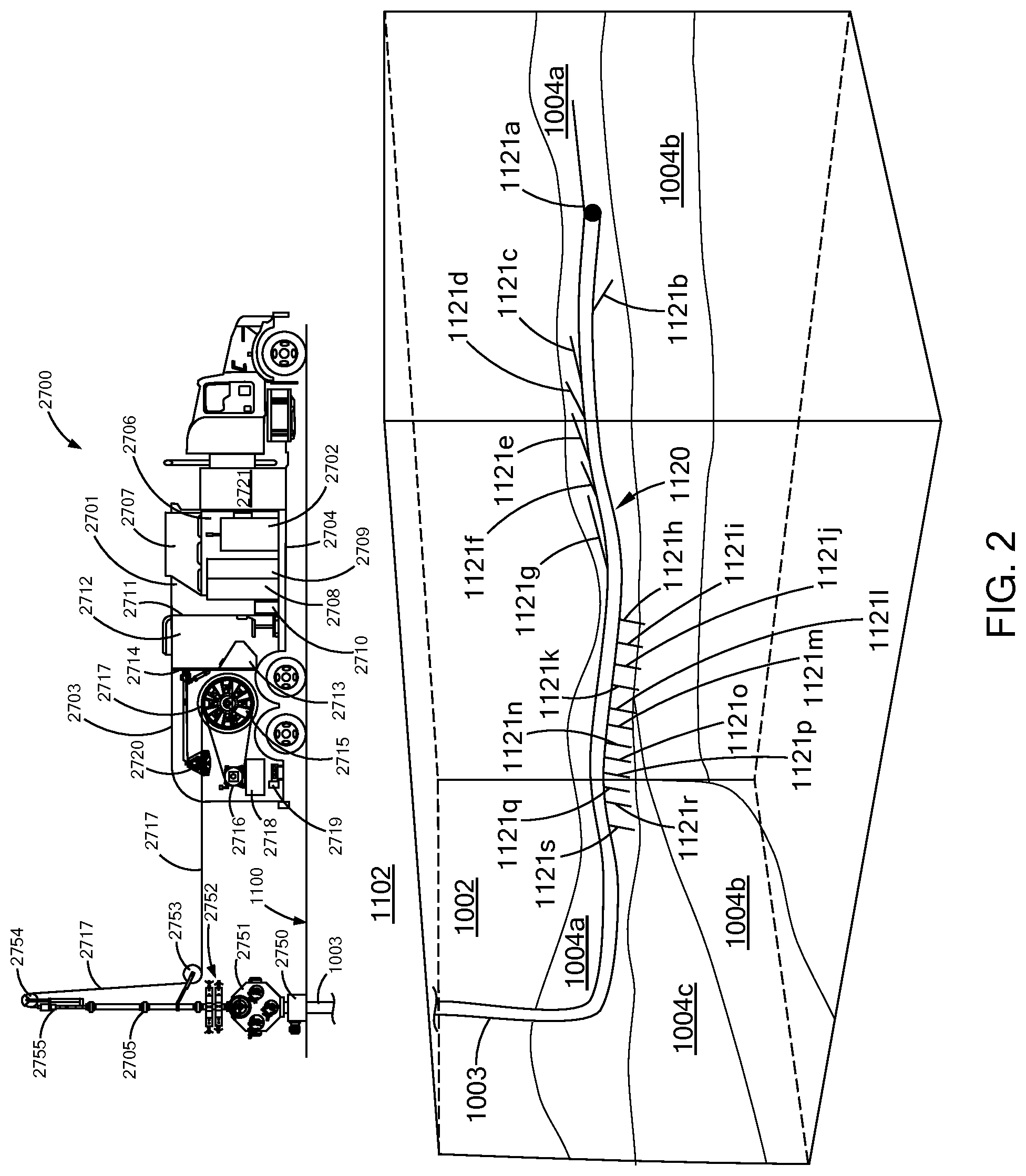
[0063] FIG. 2 is a perspective view of an embodiment of laser system providing an embodiment of a laser energy delivery pattern in accordance with the present inventions.
[0064] FIG. 3 is a perspective view of an embodiment of a laser energy delivery pattern in accordance with the present inventions.
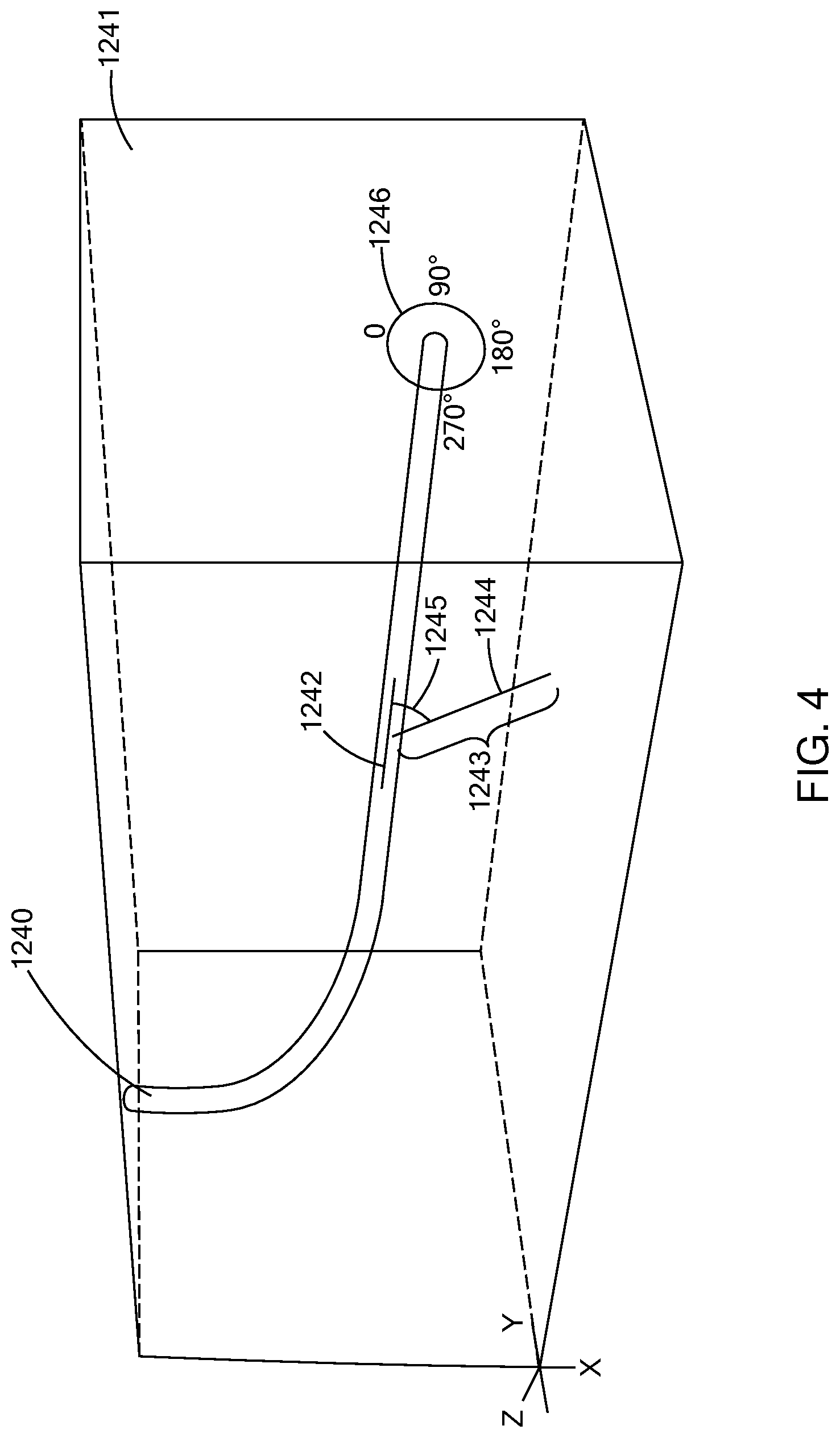
[0065] FIG. 4 is a perspective view of an embodiment of a laser energy delivery pattern in accordance with the present inventions.
[0066] FIG. 5A is a perspective view of an embodiment of a laser energy delivery pattern in accordance with the present inventions.
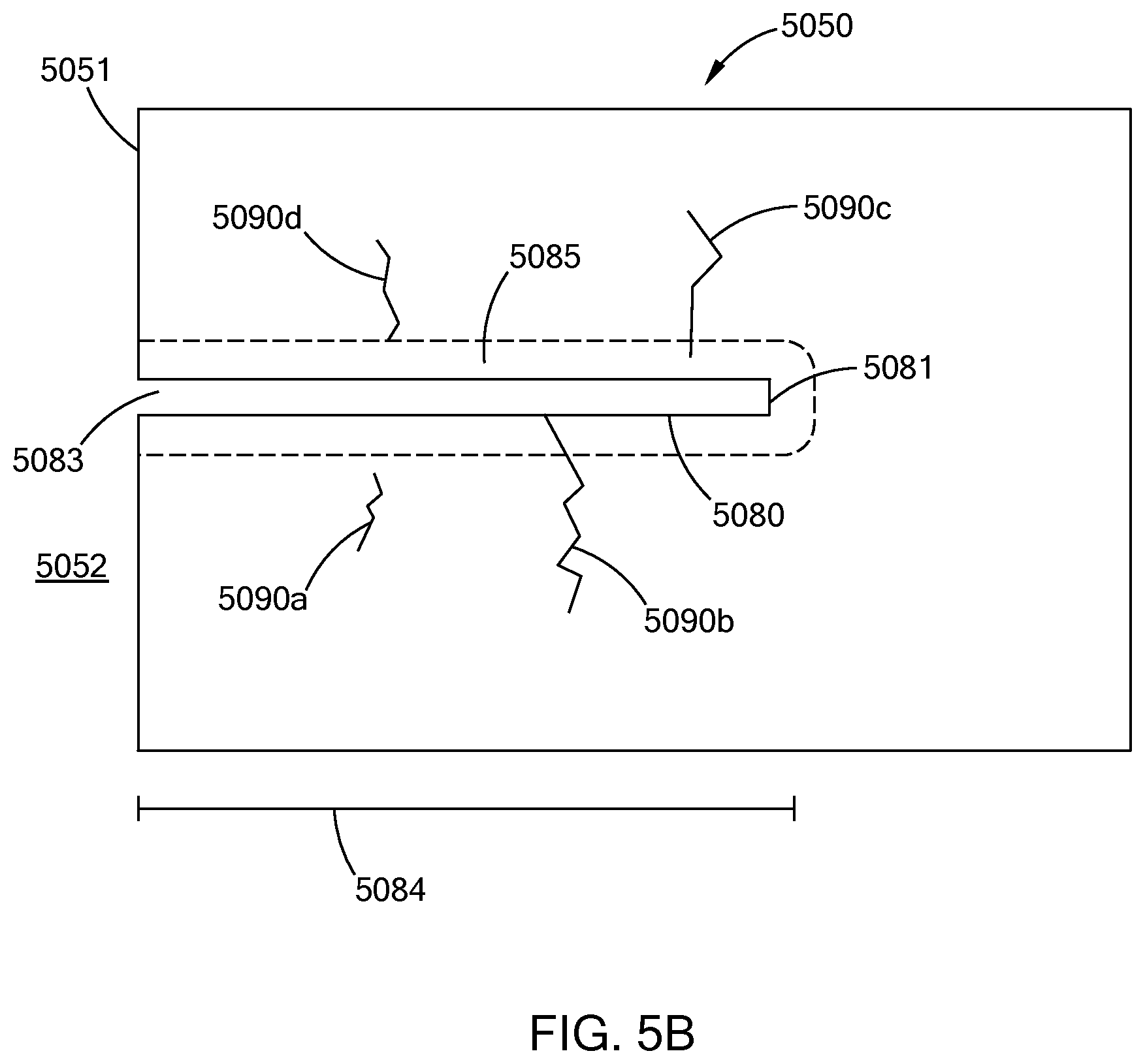
[0067] FIGS. 5B is a perspective view of an embodiment of a laser energy delivery pattern in accordance with the present inventions.
[0068] FIG. 6 is schematic view of an embodiment of a laser energy delivery pattern in accordance with the present inventions.
[0069] FIGS. 7A and 7B are plan and perspective views respectively of an embodiment of a laser energy delivery pattern in accordance with the present inventions.
[0070] FIGS. 8A and 8B are plan and perspective views respectively of an embodiment of a laser energy delivery pattern in accordance with the present inventions.
[0071] FIGS. 9A and 9B are plan and perspective views respectively of an embodiment of a laser energy delivery pattern in accordance with the present inventions.
[0072] FIG. 10 is schematic view of an embodiment of a laser perforating tool in accordance with the present inventions.
[0073] FIG. 11 is schematic view of an embodiment of a laser perforating tool in accordance with the present inventions.
[0074] FIG. 12 is schematic view of an embodiment of a laser perforating tool in accordance with the present inventions.
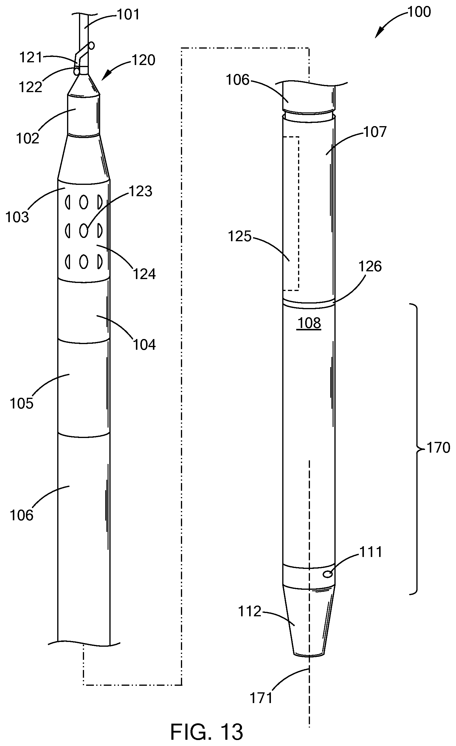
[0075] FIG. 13 is a perspective view of an embodiment of a laser perforating tool in accordance with the present inventions.
[0076] FIG. 13A is a cutaway perspective view of an embodiment of a laser perforating head in accordance with the present inventions.
[0077] FIG. 14A is a perspective view of an embodiment of a laser perforating tool in accordance with the present inventions.
[0078] FIG. 14B is a cutaway perspective view of the embodiment of FIG. 14A.
[0079] FIG. 14C is a cutaway perspective view of a component of the embodiment of FIG. 14A.
[0080] FIGS. 15A and 15B are cross sectional views of an embodiment of a laser perforation tool in accordance with the present inventions.
[0081] FIG. 16 is a perspective view of an embodiment of a laser perforating head in accordance with the present inventions.
[0082] FIG. 16A is a perspective view of the optic assembly of the embodiment of FIG. 16.
[0083] FIG. 16B is a cross section view of a laser beam launch member of the optic assembly of the embodiment of FIG. 16A.
[0084] FIG. 17 is a perspective view of an embodiment of a laser fracturing adapter in accordance with the present inventions.
[0085] FIG. 18 is schematic view of an embodiment of a laser perforating tool in accordance with the present inventions.
[0086] FIG. 19 is schematic view of an embodiment of a laser perforating tool in accordance with the present inventions.
[0087] FIG. 20 is schematic view of an embodiment of a laser perforating tool in accordance with the present inventions.
[0088] FIG. 21 is perspective view of an embodiment of a laser perforating tool in accordance with the present inventions.
[0089] FIG. 21A is cross sectional view of the embodiment of FIG. 16 as taken along line A-A of FIG. 16.
[0090] FIG. 22A is schematic view of an embodiment of a laser perforating tool in accordance with the present inventions.
[0091] FIG. 22B is schematic view of an embodiment of a laser perforating tool in accordance with the present inventions.
[0092] FIG. 23A is schematic view of an embodiment of a laser perforating tool in accordance with the present inventions.
[0093] FIG. 23B is schematic view of an embodiment of a laser perforating tool in accordance with the present inventions.
[0094] FIG. 24A is a perspective view of an embodiment of an optics assembly in accordance with the present inventions.
[0095] FIG. 24B is a cross sectional view of the embodiment of FIG. 24A.
[0096] FIG. 24C is a cross sectional view of the embodiment of FIG. 24A.
[0097] FIG. 24D is a cross sectional view of the embodiment of FIG. 24A.
[0098] FIG. 25 is a schematic of an embodiment of an optical configuration in accordance with the present inventions.
[0099] FIG. 26A is a schematic side view of an embodiment of an optical configuration in accordance with the present inventions.
[0100] FIG. 26B is a schematic plan view of the embodiment of FIG. 26A.
[0101] FIG. 27 is a schematic of an embodiment of a laser beam profile in accordance with the present inventions.
[0102] FIGS. 28A, 28B and 28C are schematic snap shots of an embodiment of a process in accordance with the present inventions.
[0103] FIG. 29 is a schematic representation of an embodiment of a process in accordance with the present inventions.
[0104] FIGS. 30A, 30B and 30C are snap shots of an embodiment of a laser perforating tool in operation in accordance with the present inventions.
[0105] FIGS. 30D to 30F are prespective views of components of the laser perforation tool of FIGS. 30A to 30C.
[0106] FIG. 31 is a schematic perspective view of an embodiment of a casing in a formation for laser perforating and fracturing in accordance with the present inventions.
[0107] FIG. 32 is a schematic perspective view of an embodiment of a casing in a formation for laser perforating and fracturing in accordance with the present inventions.
[0108] FIG. 33 is a schematic view of an embodiment of a borehole path in a formation for laser perforating and fracturing in accordance with the present inventions.
[0109] FIG. 34 is a cross sectional view of an embodiment of a laser hydraulic fracturing assembly in accordance with the present inventions.
[0110] FIG. 34A is an enlarged cross sectional view of the packer assembly of the embodiment of FIG. 34 expanded in accordance with the present inventions.
[0111] FIG. 35 is a perspective cross sectional view of an embodiment of laser perforations in accordance with the present inventions.
[0112] FIG. 36 is a perspective cross sectional view of an embodiment of laser perforations in accordance with the present inventions.
[0113] FIG. 37 is a perspective cross sectional view of an embodiment of laser perforations in accordance with the present inventions.
[0114] FIG. 38A is axial planer view of an embodiment of a laser perforating geometry following a stress plane of a formation in accordance with the present inventions.
[0115] FIG. 38B is a cross sectional view of the laser perforating geometry of FIG. 38A.
DESCRIPTION OF THE PREFERRED EMBODIMENTS
[0116] In general, the present inventions relate to systems, methods and tools to establish and enhance fluid communication between a natural resource containing formation and a well bore. In particular, the present inventions relate to hydraulic fracturing using high power lasers, high power laser tools, laser perforating, laser fracturing, and laser opening, increasing and enhancing the flow of natural resources, such as hydrocarbons and geothermal, from a formation into a production tubing or collection system. The present inventions, among other things, provide improved performance, efficiency and safety over conventional explosive based perforating guns and high pressure jetting with solids laden fluids, as well as, provide for the precise and predetermined placement of laser beam energy, in precise and predetermined energy distribution patterns. These patterns can be tailored and customized to, for example, the particular geological and structural features of a formation and pay zone, the response of the pay zone to fracturing, and other customized and adaptive hydraulic fracturing and stimulation implementations. Thus, giving rise, among other things, to never before seen, or obtainable customization of perforating and fracturing patterns and activities to precisely match the formation and geologic conditions.
[0117] Generally, once a borehole has been drilled to the desired depth and position in a formation a laser field unit is positioned near the well head. The laser field unit may have already been present at the field for laser drilling, laser pipe cutting or other laser oil field related operations. Further, the laser field unit may be close or further removed from the well head, depending upon the specific logistical constrains and considerations of the well site, as the high power laser energy can be transmitted over long distances. Although this specification focuses on hydrocarbon recovery, e.g., oil and natural gas, this focus is illustrative and it should be understood that the present inventions and their utilization have broader applications and uses. The high power laser field unit has a high power laser that provides a high power laser beam, e.g., 5 kW, 10 kW, 20 kW or more. The laser is in optical communication with a high power laser conveyance structure, which transmits the laser beam from the laser down the borehole to the location in the well where the laser hydraulic fracturing process is to occur. The high power laser beam is delivered to the borehole surface to remove material from the surface, the formation and both. Thus, the laser beam creates an opening in the borehole surface and into the formation. The laser beam delivery device can then be moved in the borehole, or taken out of the borehole entirely, as the laser cut area is isolated and the fracturing fluid is pumped into the well and into the laser made opening to fracture the formation.
[0118] In general, the laser beam has the ability to be shaped and delivered in predetermined and preselected patterns, having predetermined energy distributions, including, lines, slots, holes, and other shapes that create volumetric removals. The laser beams also have the ability to provide custom shaped openings, such as, smooth edges (e.g., bur-free), bevels, tapers, curves, lips, etc., that, for example, will provide for better control of proppants through casing into the formation, the building of a better proppant pack, the ease of moving packers and other down hole equipment into and out of the well bore, and other well operation, completion, and fracturing fluid flow enhancements. These volumetric removals can be customized for a particular formation, completion strategy, other factors and considerations, and combinations and variations of these.
[0119] Further, the laser beam delivery patterns and their resultant volumetric removals can be adapted during the hydraulic fracturing process. Thus, the laser beam delivery pattern can be shaped and predetermined, while the delivery tool is down hole or above ground, and in response to down hole information, such as for example in response to pressure data and flow data obtained during a fracturing stage. In this manner, the laser hydraulic fracturing process can be customized during the fracturing stages, by cutting new, different, or adapted openings to enhance a subsequent stage in a fracturing operation, correct a less than optimal result from an earlier fracturing stage, and combinations and variations of these.
[0120] Further, the laser beam and the volumetric removal patterns can be customized, or predetermined, to perform operations such as correction of fracture jobs, reentry and other recompletion, or activities for increase the production of a failing or failed well. The laser beam may additionally be used to seal openings, such as perforations in or damaged sections of casing, which could then enable the fracing of a different zone or area of the well. The laser's ability to seal and the remove material from the borehole in a selected and predetermined manner, as well as in a repeating manner, provides the capabilities to address many and varied production and completion related problems and difficulties, such as for example if a zone is producing water and/or gas.
[0121] Turning to FIG. 1 there is provided a perspective view of an embodiment of a laser hydraulic fracturing site 1. Thus, positioned near the well head 14 there is a laser field unit 2, pumping trucks 6, proppant storage containers 10, 11, a proppant feeder assembly 9, a blender, (e.g., mixing truck) 8, and fracturing fluid holding units 12. As will be understood by one of skill in the hydraulic fracturing arts, FIG. 1 is an illustration and simplification of a fracturing site. Such sites may have more, different, and other pieces of equipment such as pumps, holding tanks, mixers, and chemical holding units, mixing and addition equipment, lines, valves and transferring equipment, as well as control and monitoring equipment.
[0122] The laser field unit has a high power laser conveyance structure or laser umbilical 3, which enters the well head 14 through laser fracturing adapter 4. The laser fracturing adapter 4 has a high pressure line 5 that transfers high pressure fracturing fluid from the pump trucks 6 into the well. The laser fracturing adapter 4 has packers or other pressure managing apparatus, known to those of skill in the art, to enable the insertion and removal of a laser fracturing sub, a laser fracturing tool, a laser perforating tool and the movement of the laser umbilical into and out of the well. The well head 4 may also have further well control devices associated with it, such as a BOP.
[0123] Fracturing fluid from holding units 12 is transferred through lines 13 to mixing truck 8, where proppant from storage containers 10, 11 is feed by assembly 9 and mixed with the fracturing fluid. The fracturing fluid and proppant mixture is the transferred to the pump trucks 6, by line 7.
[0124] In this manner the laser perforating and cutting applications can take place, the well can be appropriately isolated, e.g., a fracture stage, zone or predetermined section, and the fracturing fluid can be pumped into the well under pressure to fracture the formation.
[0125] An embodiment of a high power laser system and its deployment and use in the field, to provide a custom laser perforation and fracturing pattern to a formation, is shown in FIG. 2. Thus, there is provided a laser field unit, such as the embodiment of a mobile laser conveyance truck (MLCT) 2700. The MLCT 2700 has a laser cabin 2701 and a handling apparatus cabin 2703, which is adjacent the laser cabin. The laser cabin 2701 and the handling cabin 2703 are located on a truck chassis 2704. In this embodiment the delivery tool could be any of the laser delivery tools of the embodiments in this specification.
[0126] The laser cabin 2701 houses a high power fiber laser 2702, (e.g., 20 kW; wavelength of 1070-1080 nm); a chiller assembly 2706, which has an air management system 2707 to vent air to the outside of the laser cabin and to bring fresh air in to the chiller (not shown in the drawing). The laser cabin also has two holding tanks 2708, 2709. These tanks are used to hold fluids needed for the operation of the laser and the chiller during down time and transit. The tanks have heating units to control the temperature of the tank and in particular to prevent the contents from freezing, if power or the heating and cooling system for the laser cabin was not operating. A control system 2710 for the laser and related components is provided in the laser cabin 2703. A partition 2711 separates the interior of the laser cabin from the operator booth 2712.
[0127] The operator booth contains a control panel and control system 2713 for operating the laser, the handling apparatus, and other components of the system. The operator booth 2712 is separated from the handling apparatus cabin 2703 by partition 2714.
[0128] The handling apparatus cabin 2703 contains a spool 2715 (e.g., about 6 ft OD, barrel or axle OD of about 3 feet, and a width of about 6 feet) holding about 10,000 feet of the conveyance structure 2717. The spool 2715 has a motor drive assembly 2716 that rotates the spool. The spool has a holding tank 2718 for fluids that may be used with a laser tool or otherwise pumped through the conveyance structure and has a valve assembly for receiving high pressure gas or liquids for flowing through the conveyance structure.
[0129] The laser 2702 is optically associated with the conveyance structure 2717 on the spool 2715 by way of an optical fiber and optical slip ring (not shown in the figures). The fluid tank 2718 and the valve assembly 2719 are in fluid communication with the conveyance structure 2717 on the spool 2715 by way of a rotary slip ring (not shown).
[0130] The laser cabin 2701 and handling apparatus cabin 2703 have access doors or panels (not shown in the figures) for access to the components and equipment, to for example permit repair, replacement and servicing. At the back of the handling apparatus cabin 2703 there are door(s) (not shown in the figure) that open during deployment for the conveyance structure to be taken off the spool. The MLCT 2700 has an electrical generator 2721 to provide electrical power to the system.
[0131] The MLCT 2700 is on the surface 1100 of the earth 1102, positioned near a wellhead 2750 of a borehole 1003, and having a Christmas tree 2751, a BOP 2752 and a lubricator 2705. The conveyance structure 2717 travels through winder 2720 (.e.g., line guide, level wind) to a first sheave 2753, to a second sheave 2754, which has a weight sensor 2755 associated with it. Sheaves 2753, 2754 make up an optical block, which is a combination of sheaves to provide for a path, or configuration of the conveyance structure, and also to permit the movement of the conveyance in and out of the borehole, while not significantly interfering with, or otherwise significantly adversely affecting the transmission of the high power laser beam. The weight sensor 2755 may be associated with sheave 2753 or the conveyance structure 2717. The conveyance structure 2717 enters into the top of the lubricator and is advanced through the BOP 2752, tree 2751 and wellhead 2750 into the borehole 1003 below the surface of the earth 1100. The sheaves 2753, 2754 have a diameter of about 3 feet. In this deployment path for the conveyance structure the conveyance structure passes through several radii of curvature, e.g., the spool and the first and second sheaves. These radii are all equal to or large than the minimum bend radius of the high power optical fiber in the conveyance structure. Thus, the conveyance structure deployment path would not exceed (i.e., have a bend that is tighter than the minimum radius of curvature) the minimum bend radius of the fiber.
[0132] As seen in the embodiment of FIG. 2, the MLCT 2700 is positioned over a formation 1002, in the earth 1102. The formation 1002 is shown as being freestanding, e.g., a block of material, for the purpose of clarity in the figure. It being understood that the formation may be deep within the earth, nearer to the surface such as in some shale gas fields and that the orientation of borehole 1003 may be from vertical, to the essentially horizontal shown in FIG. 2, to up turned, as well as branched.
[0133] In FIG. 2, the piping, pumps etc., for the delivery of the fracturing fluid are not shown. Once the laser beam(s) have been delivered the the conveyance structure and the delivery tool can be removed from the well and the fracturing fluid delivery equipment connected to the well, or the fracturing fluid delivery equipment can be associated with the well, and the lubricator isolated from the pressure and flow of the fracturing fluid, while the fluid is being delivered, in this manner the conveyance structure and laser delivery tool may be left within the well during fracturing, partially removed from the well, or entirely removed from the well, and combinations and variation of these.
[0134] The formation 1002 has various geological formations and properties, e.g., 1004a, 1004b, 1004c. The geological properties and characteristic of the formation and hydrocarbon deposit may have been previously determined by seismic, well logging and other means known to the arts. Based upon this information a custom laser energy delivery perforating pattern 1120 was designed to extend from borehole 1003 and is delivered to the formation 1002. The laser perforating pattern 1120 has a series of laser perforations 1121a-1121s.
[0135] The position, spacing and orientation of these laser perforations 1121a-1121s is based in whole, or in part, upon the characteristics and features of the formation in which the laser pattern is delivered. As can be seen from FIG. 2, and for illustration purposes the perforation may have different lengths, may have different orientations to vertical, may have different angles with respect to the longitudinal axis of the borehole, and combinations and variations of these and other properties. Preferably, the perforation pattern and laser delivery pattern, because of its fracturing and weakening effect on the formation, is predetermined to enhance, augment, redo, or even replace hydraulic fracturing.
[0136] Turning to FIG. 3 there is shown an embodiment of laser fracturing zone. A borehole 1140 in a section of a formation 1141. An essentially horizontal laser perforation pattern 1142 has been made from the borehole, resulting in a predetermined laser effected zone 1143, e.g., custom geometry (shown in dashed lines), which zone has laser induced fracturing. Hydraulic fracturing operations can then be applied using this custom geometry, to further enhance fluid communication between the borehole and the formation. Preferably, the hydraulic fracture zone 1150 is extended from the well bore, to and beyond the laser effected zone 1143. In this manner, the surface area exposed in the formation from the fracturing, is equal to the laser effected zone, and preferable larger, and substantially larger than the laser effected zone.
[0137] Turning to FIG. 4 there is shown a borehole 1240 in a section of a formation 1241. The borehole has a single laser perforation 1244. A single perforation is used in this figure to illustrate the different variables that are controllable through laser perforation and which can, in whole or in part, be used to provide a predetermined laser perforation delivery pattern, and custom volumetric removal. The laser perforation can be varied in length 1243. The angle 1245 that the perforation forms with the longitudinal axis of the borehole (also typically the laser perforation tool) can be varied. The orientation around the borehole, e.g., degrees 1246 around the borehole can be varied, e.g., for 0.degree. to 90.degree. to 180.degree. to 270.degree. to 0.degree., and thus, any point point around 360.degree.. Additional, since it is preferred to have a multiple perforations, there spacing can be varied, and the other variables can be changed from one adjacent perforation to the next. This ability to predetermine and adapt these variables provides the further ability to have predetermined volumetric removals, and adaptive volumetric removals to conditions, data and information that develop during fracturing, fracturing stages, production, and combinations and variations of these, as well as, other down hole conditions.
[0138] Turning to FIG. 38A and 38B there is shown an axil planer view and cross sectional view of a laser perforating geometry in a formation in relation to the stress planes in the formation. Thus, there is a laser tool 3800 in a borehole 3801 in a formation 3807 that has a stress direction shown by arrows, e.g., 3802. The laser tool 3800 has a range or area 3803 where the laser beam can be delivered, which for example could be a fan shaped delivery volumetrically removing the entire area. This area is within and the direction of stress 3802, and thus, the laser tool 3800 can deliver the laser beam in the direction of the stress, following the direction of stress, and parallel to the direction of stress. The limited ability of conventional tools is shown by perforation range 3810.
[0139] In additional to providing an entire laser perforation pattern based upon formation information, in whole, in part or without such information, it is possible to construct an evolving or adaptive laser perforation pattern based upon real time data and information, such as pressure testing in the well. Thus, for example, straddle packers may be employed with the laser perforation tool. The packers are set and the area is pressured up; changes, as measured with a caliper assembly for example, are then measured. From this information the strength of the formation and its strength in different directions can be measured and used to direct the laser beam to provide the optimum configuration of laser perforations for that specifically tested section of the formation. Additionally, sonic wireline tools may also be utilized to measure stress direction.
[0140] Turning to FIGS. 5A and 5B there are shown in FIG. 5A a prospective view a section of a formation 5050, and in FIG. 5B a cross sectional view of the formation 5050. The formation 5050 is shown as being freestanding, e.g., a block of material, for the purpose of clarity in the figure. It being understood that the formation may be deep within the earth, nearer to the surface such as in some shale gas fields, and preferably in a hydrocarbon rich or pay zone of the formation, and that the face 5051 forms a part of, or is adjacent to, a borehole 5052 (as seen in FIG. 5B). Further although some boreholes are represented as being vertical, this is merely for illustration purposes and it should be recognized that the boreholes may have any orientation.
[0141] A laser cut hole 5080 extends into the formation 5050 from the hole opening 5083 to the back of the hole 5081. Around the hole 5080 is an area 5085 of laser affected formation. In this area 5085 the formation is weakened, substantially weakened, fractured or essentially structurally destroyed. Additionally, the laser cutting process forms cracks or fractures, i.e., laser induced fracturing, in the formation. By way of example, fracture 5090a is an independent fracture and does not extend to, or into, the laser affected area 5085, the hole 5080 or another fracture. Fracture 5090b extends into and through the laser affected area 5085 into the hole 5081. Additionally, fracture 5090b is made up of two associated cracks that are not fully connected. Fracture 5090c extends to, and into, the laser affected area 5085 but does not extend to the hole 5080. Fracture 5090d extends to, but not into the laser affected area 5085.
[0142] The fractures 5090a, 5090b, 5090c and 5090d are merely schematic representation of the laser induced fractures that can occur in the formation, such as rock, earth, rock layer formations and hard rocks, including for example granite, basalt, sandstone, dolomite, sand, salt, limestone and shale rock. In the formation, and especially in formations that have a tendency, and a high tendency for thermal-mechanical fracturing, in a 10 foot section of laser cut hole there may be about 10, about 20, about 50 or more such fractures, and these fractures may be tortious, substantially linear, e.g., such as a crack along a fracture line, interconnected to greater and lessor extents, and combinations and variations of these and other geometric and volumetric configurations. These laser fractures may also be of varying size, e.g., length, diameter, or distance of separation. Thus, they may vary from micro fractures, to hairline fractures, to total and extended separation of sections having considerable lengths. These laser induced fractures may open up, provide or give rise to, additional surface area for the flow of hydrocarbons. Further, these laser induced fractures provide additional paths for fracturing fluid to move through and extend out from the borehole, and provide the ability for the fracturing fluid to leave proppant behind in these an other fractures in the laser effected zone and extending out beyond that zone. Thus, resulting in a substantial increase in total exposed surface area from a laser hydraulic fracture than would be obtained from conventional fracturing alone.
[0143] The depth or length of the lase cut hole can be controlled by determining the rate, e.g., inches/min, at which the hole is advanced for a particular laser beam, configuration with respect to the work surface of the formation, and type of formation. Thus, based upon the advancement rate, the depth of the hole can be predetermined by firing the laser for a preset time.
[0144] The rate and extent of the laser fracturing, e.g., laser induced crack propagation, may be monitored by sensing and monitoring devices, such as acoustical devices, acoustical geological sensing devices, and other types of geological, sensing and surveying type devices. In this manner the rate and extent of the laser fracturing may be controlled real time, by adjusting the laser beam properties based upon the sensing data.
[0145] Cuts in, sectioning of, and the volumetric removal of the formation down hole can be accomplished by delivering the laser beam energy to the formation in preselected and predetermined energy distribution patterns. These patterns can be done with a single laser beam, or with multiple laser beams. For example, these patterns can be: a linear cut; a pie shaped cut; a cut appearing like the shape of an automobile cam shaft; a circular cut; an elliptical cut; a square cut; a spiral cut; a pattern of connected cuts; a pattern of connected linear cuts, a pattern of radially extending cuts, e.g., spokes on a wheel; a circle and radial cut pattern, e.g., cutting pieces of a pie; a pattern of spaced apart holes, such as in a line, in a circle, in a spiral, or other pattern, as well as other patterns and arrangements. The patterns, whether lines, staggered holes, others, or combinations thereof, can be traced along, e.g., specifically targeted in a predetermined manner, a feature of the formation, such as, a geologic joints, bedding layers, or other naturally occurring features of a formation that may enhance, exploited or built upon to increase the fluid connectivity between the borehole and the hydrocarbons in the formation.
[0146] Thus, for example, in determining a laser beam delivery pattern to provide a predetermined and preselected laser beam energy distribution pattern, the spacing of cut lines, or staggered holes, in the formation, preferably may be such that the laser affect zones are slightly removed from one another, adjacent to one another but do not overlap, or overlap only slightly. In this manner, the maximum volume of the formation will be laser affect, i.e., weakened, fractured or perforated with the minimum amount of total energy.
[0147] FIG. 6 shows an embodiment of a stepping down fan perforating pattern that can be implemented with the present laser perforation tools. In this pattern a series of progressively smaller fan shapes 2262a, 2262b, 2262c, 2262d are cut into formation 2261 moving away from borehole 2260. The dashed lines indicated the end of a first fan pattern that was cut through with the deeper, and later in time, fan pattern.
[0148] FIG. 7A is a plan view looking down borehole 2300 showing an embodiment of a fan, or pie shape perforation 2301 in formation 2302. FIG. 7B is a perspective view along the longitudinal axis of borehole 2300 showing that pie shape perforation 2301 is a volumetric shape extending along the borehole 2300. The length of pie shaped perforation 2301 may be a few inches to a few feet, tens of feet or more. Additionally more than one pie shaped perforation can be space along the length of the borehole.
[0149] FIG. 8A is a plan view looking down borehole 2400 showing an embodiment of a fan, or pie shape perforation 2401 in formation 2402. FIG. 8B is a perspective view along the longitudinal axis of borehole 2400 showing that there are a number of pie shape perforation 2401, 2403, 2405, 2407, 2409, 2411, 2413 spaced along the length of the borehole 2400 and that each is a volumetric shape extending along the length of the borehole 2400. The length of pie shaped perforation 2401, 2403, 2405, 2407, 2409, 2411, 2413, may be a few inches to a few feet, tens of feet or more. Their lengths, and their spacing may be uniform, or it may be staged to, for example, match to formation characteristics to optimize fluid communication between the borehole and the formation.
[0150] FIG. 9A is a plan view looking down borehole 2500 showing an embodiment of a disk shaped perforation 2501 in formation 2502. FIG. 9B is a perspective view along the longitudinal axis of borehole 2500 showing that there are a number of disk shape perforation 2501, 2503, spaced along the length of the borehole 2501 and that each is a volumetric shape extending along the length of the borehole 2500. The length of disk shaped perforation 2501, 2503 may be an inch, few inches to a few feet, but should not be so long as to adversely effect the stability of the well bore. Their lengths, and their spacing may be uniform, or it may be staged to, for example, match to formation characteristics to optimize fluid communication between the borehole and the formation.
[0151] The laser perforation patterns, beam delivery patterns have the capability to remove controlled volumes of material for each perforation, or discrete geometric shape. Thus, the volumetric removals, for discrete shape, e.g., disc, cylinder, line, could be greater than about 0.1 cubic inches (in.sup.3), greater than about 0.2 in.sup.3, greater than about 1 in.sup.3, greater than about 4 in.sup.3, greater than about 20 in.sup.3, greater than about 50 in.sup.3, and greater than about 100 in.sup.3, and greater than about 150 in.sup.3 (it being understood that greater and lessor volumes of removal are also contemplated) The laser beam removes material by, among other things, spalling, melting, vaporizing and combinations of these processes. For example the following Table 1 provides volumetric removals for a discrete shape, i.e., a disc, for particular casing, disc outer diameter and thickness.
TABLE-US-00001 TABLE 1 Disc OD 5 Disc OD 5 Disc OD 5 Disc OD 7 Disc OD 7 Disc OD 7 in, thickness in, thickness in, thickness in, thickness in, thickness in, thickness 1/4 in -- 1/2 in -- 1 in -- 1/4 in -- 1/2 in -- 1 in -- Casing/pipe volume volume volume volume volume volume outer removed in removed in removed in removed in removed in removed in diameter in in.sup.3 in.sup.3 in.sup.3 in.sup.3 in.sup.3 in.sup.3 1 4.71 9.42 18.84 9.42 18.84 37.68 21/2 3.68 7.36 14.72 8.39 16.78 33.56 5 1.77 3.54 7.08 12.76 25.52 51.04 41/2 0.93 1.86 3.72 5.64 11.28 22.56 Disc OD 10 Disc OD 10 Disc OD 10 Disc OD 20 Disc OD 20 Disc OD 20 in, thickness in, thickness in, thickness in, thickness in, thickness in, thickness 1/4 in -- 1/2 in -- 1 in -- 1/4 in -- 1/2 in -- 1 in -- volume volume volume volume volume volume removed in removed in removed in removed in removed in removed in in.sup.3 in.sup.3 in.sup.3 in.sup.3 in.sup.3 in.sup.3 71/2 28.23 17.18 34.36 67.49 134.98 269.96 75/8 27.87 16.46 32.92 67.13 134.26 268.52 85/8 24.68 10.08 20.16 63.94 127.88 255.76
[0152] Laser perforating tools and operations may find considerable uses, for example, in shales and shale formations and other unconventional or difficult to produce from formations. For example, in shales for unconventional extraction of gas and oil there is essentially no permeability, and in many cases no permeability. The current operations to access this rock and make it productive are to drill a 6 to 12 inch diameter borehole, thousands of feet long with a mechanical rig and bit, and then perforate on the order of inches using explosives. Once the perforations are formed tens or hundreds of thousands of gallons of fracturing fluid containing propping agents are pumped into the well at high pressure and are used to create fractures which increased the productivity of the well.
[0153] The high power laser perforating tools can greatly improve on this conventional operation by creating a custom geometry (e.g. shape, length, entrance area, thickness) with a laser. This custom geometry can stem off a main borehole in any orientation and direction, which in turn will initiate a fracture that is more productive than existing conventional methods, by exposing more rock and positioning the fractures in optimum stress planes, resulting in even greater surface area upon hydraulic fracturing.
[0154] Generally, fracturing in rocks at depth is suppressed by the confining pressure, from the weight of the rocks and earth above. The force of the overlying rocks is particularly suppressive of fracturing in the situation of tensile fractures, e.g., Mode 1 fractures. These fractures require the walls of the fracture to move apart, working against this confining pressure.
[0155] Hydraulic fracturing or fracing is used to increase the fluid communication between the borehole and the formation. Thus, it can restore, maintain, and increase the rate at which fluids, such as petroleum, water, and natural gas are produced from reservoirs in formations.
[0156] Thus, it has long been desirable to create conductive fractures in the rock, which can be pivotal to extract gas and oil from, for example, shale reservoirs because of the extremely low natural permeability of shale, which is measured for typical shales in the microdarcy to nanodarcy range. These fractures provide a conductive path connecting a larger volume of the reservoir to the borehole.
[0157] The custom geometries that can be created with laser perforating can provide enhanced, more predictable, and more controllable predetermined conductive paths that result from hydraulic fracturing. Thus, the laser perforation custom geometry can increase the efficiency of hydraulic fracturing and hydrocarbon production from a well.
[0158] Laser perforated custom geometries for hydraulic fracturing have many advantages in many, if not all well types, and particularly have advantages in horizontal drilling, which involves wellbores where the borehole is completed as a "lateral" that extends parallel to the hydrocarbon containing rock layer. For example, lateral boreholes can extend 1,500 to 5,000 feet (460 to 1,500 m) in the Barnett Shale basin in Texas, and up to 10,000 feet (3,000 m) in the Bakken formation in North Dakota. In contrast, a vertical well only accesses the thickness of the rock layer, typically 50-300 feet (15-91 m). Mechanical drilling, however, typically causes damage to the pore space, e.g., formation structure, at the wellbore wall, reducing the permeability at and near the wellbore. This reduces flow into the borehole from the surrounding rock formation, and partially seals off the borehole from the surrounding rock. Custom geometries, from the laser perforation, enable hydraulic fracturing in these wells to provide, restore and increase permeability and the productivity of the well; and to also do so in a more efficient and potentially cost effective manner than with previous perforating practies.
[0159] Thus, laser hydraulic fracturing, its systems tools and methods, as well as, the laser perforating tools, and laser energy distribution patterns, which can provide custom geometries, laser fractures and customer volumetric removals for hydraulic fracturing operations, have the potential to greatly increase hydrocarbon production, especially form unconventional sources.
[0160] Turning to FIG. 34, there is provided an embodiment of a laser hydraulic fracturing assembly 900 deployed in a borehole at the beginning of a laser hydraulic fracturing operation.
[0161] In general, embodiments of laser hydraulic fracturing assemblies can have the capability to perform perforating operations in several predetermined zones or sections of the borehole. They can also preferably have the capability to isolate those sections, and to have the laser tool remain in the borehole during a pressure or flow operations, such as a hydraulic fracturing operation, if one should be required.
[0162] Thus, in general, a laser tool is located inside a sleeve, which is inserted into the borehole. (The sleeve may be lowered into the borehole via any type of conveyance structure, however, if flow or pressure operations are intended it should preferably be lowered via coiled tubing.) The sleeve has a series of spaced apart packers assemblies. These packer assemblies are configured to have the capability to expand outwardly and seal against the borehole wall, and also to expand inwardly and seal against the laser tool or the high power laser conveyance structure.
[0163] Thus, the outer packers can seal against the borehole wall isolating a section of the borehole between them. The inner packers can seal against the laser tool, effectively creating a plug (which also protects the laser optical components and other components of the laser tool from any high pressures or flows that may be above the "plug.") In this manner the laser hydraulic fracturing assembly has the capability to perform many varied perforation, cutting, welding, pressure, and flow operations; to perform these operations in multiple predetermined and isolated sections along the length of the borehole; and to perform these multiple operations along the length of the borehole while remaining in the borehole.
[0164] Thus, for example, a laser fracturing assembly can be lowered to the bottom of a borehole. The sleeve of the laser fracturing assembly has, for example, 10 sets of outwardly expanding spaced apart packers, which are distributed along the length of the sleeve. The lower most (closest to the bottom of the borehole) set of packers on the sleeve are expanded and isolate a section of the borehole between them.
[0165] The laser tool is positioned inside of the sleeve in the section of the sleeve between to the two expanded packers. The laser tool delivers the laser beam, readily cutting through the sleeve and performing the desired laser perforating operation on the borehole (either cased, multiple casing, or open hole).
[0166] The laser tool is then moved to a position in the sleeve adjacent the lower most expanded packer. When the laser tool is at this position, the inner packer is activated, expanding inwardly, sealing against the laser tool and creating a plug (e.g., the inner packer sealing against the laser tool and the adjacent outer packer, which is still activated sealing against the bore hole). A pressure and flow operation, e.g., hydraulic fracturing can then be performed on the isolated section of the borehole.
[0167] Once completed, the next set of up-hole packers can be expanded and the laser tool moved into position and the process repeated. In this manner, the laser tool, and related operations, can move in a serial manner from the down hole packer set (closest to the bottom of the borehole) to the upper most packer set (closest to the top of the hole).
[0168] It should further be understood, that this assembly provides great flexibility in the number and types of processes, operations, perforation patterns, reperforation patterns, hydraulic fractures, and other procedures and operations that can be performed along a length of a borehole, in isolated section of the borehole along that length, and preferably that can be performed in a single down hole trip.
[0169] Turning again to the embodiment of FIG. 34, the laser hydraulic fracturing assembly 900 is attached by joint 904 to coil tubing 903. The coil tubing 903 has been used to lower the laser hydraulic fracturing assembly 900 into a desired position within the borehole 901, in formation 902. Positioned within assembly 900 is laser cutting or perforating tool 910. Laser perforating tool 910 may be moved into the borehole with assembly 900, or it may moved into position after assembly 900 is situated in the borehole.
[0170] Assembly 900 has a sleeve or outer housing 920, with a series of packer assemblies 905, 906, 907, 908, located along the length of the sleeve 920. In this embodiment packer assembly 908 would be the bottom most assembly, e.g., closest to the bottom of the borehole, and packer assembly 905 would be the upper most assembly, e.g., closes to the top of the borehole. More or less packer assemblies may be used on a laser hydraulic fracturing assembly. Each packer assembly has an outer expandable sealing member 905a, 906a, 907a, 908a, and an adjacent inner expandable sealing member 905b, 906b, 907b, 908b. These packer assemblies are spaced, e.g., positioned along the length of the sleeve 920 of the laser hydraulic fracturing assembly 900. They provide predetermined locations, sections or zones where laser perforations can be made. They also provide for the performance of flow and pressure operations, through the laser perforations, on these isolated sections of the borehole, such as for example, where fracturing fluid and pressures will be applied to the formation 902. Thus, their number, spacing and frequency can vary and will be determined, in part, by information regarding the nature and characteristics of the formation and hydrocarbon sought to be recovered.
[0171] The laser perforating tool 910 has a high pressure sealing section 911. This section is configured to seal against the laser conveyance structure 916, and be engaged by, and thus seal against the inner sealing member, e.g., 908b, when that sealing member is extended inwardly. In this manner the sealing section 911 when engaged by an inner sealing member protects the the laser perforating tool 910 from any up hole conditions, such as for example, the pressures and flows from an hydraulic fracturing operation. The laser sealing section 911 may also have its own expandable device, which could be expanded to engage the inner sealing member 908b, or could be expanded to engage and seal against the inner wall of the sleeve 920, or even potentially against the inner wall of another tubular located around the laser tool. (In this manner, the position of the laser perforating tool 910 would not be limited to being adjacent a packer assembly, e.g., 908, during an hydraulic fracturing stage).
[0172] The laser perforating tool 910 has a laser cutter section 912, which may contain a laser optics package for shaping and determining the laser beam properties, a mirror or prism for changing the direction of the laser beam, and a beam steering assembly for scanning or otherwise directing the laser beam. For example, the cutter section may have a digital micromirror device ("DMD") to direct the laser beam in a predetermined path, to give rise to a predetermined volumetric removal. The laser cutter section 912 may also have a nozzle, jet or other components to assist in the delivery of the laser beam, along a predetermined laser beam path, to it is target.
[0173] The laser cutter section 912 is optically associated with the conveyance structure 916, by for example, a high power connector. The conveyance structure 916 transmits the high power laser beam from a high power laser, preferably above the surface, to the cutting head section 912, where it is launch toward the target, e.g., the borehole wall. The conveyance structure 916 may be a high power optical fiber having a core diameter of at least about 300 microns, an inner protective sleeve of for example Teflon, which is located between the exterior of the optical fiber and the inner surface of a metal tube. The metal tube is then wrapped with carbon fiber, preferably in a braided fashion to provide strength to the metal tube and reduce, if not prevent the stretching of the tube. The woven carbon fiber outer wrap is then impregnated with an abrasion resistant resin or coating, which is also preferably high temperature, such as polyimide. The conveyance structure may also include other line structures for data, power, hydraulics for the the laser perforating tool 910, or these lines to the extent needed may be places in one or more other conveyance structures.
[0174] The laser perforating tool 910 has an instruments section 913, which may have position location equipment, logging equipment, sensors and the like. In particular and preferably, the instrument section 913 has a locator device that can detect and determine the position of the laser perforating tool 910 with respect to a packer assembly, e.g., 908.
[0175] The laser perforating tool, has a motive section 914, which may contain an axial extending device, such as a ball screw assembly, for moving the laser cutting head in a predetermined and controlled rate axially along the length of the borehole. Depending upon the laser beam steering capabilities of the laser cutter section 912, the laser motive section 914 may also have a rotation device for rotating the laser head to a particular orientation regarding the borehole (see, e.g., FIG. 4, item 1246).
[0176] The laser perforating tool 910 has a tractor section 915, which can be used to initially position the tool 910 in the coiled tubing, can be used to move the tool from one section of packer assemblies to the next, e.g., moving from packer assembly 908 to packer assembly 907. The tractor section 915 may also serve to anchor the tool 910 as the laser cutting head is moved during a laser perforating operation, and to anchor the tool 910 when the inner sealing members are sealed during a fracturing stage. Depending up the vertical slope of the borehole, the tractor section 915 may only be an anchoring section as the movement of the tool 910 in the borehole can be accomplished by gravity and the lowering or rising of the conveyance structure 916.
[0177] This embodiment of the laser hydraulic fracturing assembly 900 and its laser perforating tool 910 are illustrative. Thus, additional and different components of the various sections may be used, additional or fewer sections may be used, the components of one section may be located in a different section, duplicate and redundant components may be used, and the the functions of one component may be spread across or combined with other components. Preferably, the various sections of the laser perforating tool provide the tool with the capability to perform precision and predetermined volumetric removals by directing and moving the laser beam in predetermined angles and patterns, for example, as shown in and described regarding the embodiment of FIG. 4.
[0178] The laser hydraulic fracturing assembly 900 provides many varied methods of operation to perform laser hydraulic fractures. Turning to FIG. 9, the tractor section 915 is anchored against the inner wall of the sleeve 920. The laser cutter is moved at a predetermined rate and manner by the motive section 914. In this example the laser cutter is moved axially for a distance of three feet between packer assembly 908 and assembly 907, to perforate the borehole, by cutting a slot in the borehole wall and formation. The laser readily cuts through sleeve 920, which does not interfere with the laser perforation of the borehole. (To the extent that the packer assemblies are a greater distance apart, for example 15 feet, and the length of the slot is desired to be 10 feet, once the full extension of the motive device 914 is reached, e.g., 3 feet, the tractor can be moved forward as the motive device is retracted, the tractor can then be anchored and the cut continued.) In addition to a slot, the laser cutter could be moved and create holes at predetermined locations, or any other predetermined perforation pattern.
[0179] Once the desired laser perforations are made the laser cutter 912 is retracted back by the motive section 914, to the point where the sealing section 911 is adjacent to the inner packer 908b. At this point the inner packer 908b is sealed against the sealing section 911. The inner packer 908b and the sealing section 911 form a pressure tight seal. This seal has sufficient strength, e.g., is sufficiently tight and strong, to withstand the pressures and flows during e.g., a fracturing operation. The outer sealing member 908a of packer assembly 908 and the outer sealing member 907a of packer assembly 907 are then extended to seal against the inner surface of the borehole 901. In this manner the packer assembly 908, in conjunction with sealing section 911 form a plug in the borehole, as shown in FIG. 34A. Further, in this manner packer assemblies 907 and 908 form an isolation zone along the length of the borehole.
[0180] Once the packers sealing members 907a, 908a, and 908b are set, hydraulic fracturing can begin. The fracturing fluid is pumped down the coiled tubing 903, into the sleeve 920, out of the sleeve through the laser cut openings, and into the laser perforations in the formation fracturing the formation.
[0181] As the pressures and flows are monitored, if it is believed that less than optimal fracturing is occurring, the pressure and flow of the fracturing fluid can be reduced and stopped. The packer 908b can be disengaged, and subsequent laser cutting, and perforating operations, can be commented in the section between packer assembly 908 and 907. Once the subsequent, adaptive, laser perforation is completed, the cutter head 912 is retracted, the inner seal 908b is set, and the hydraulic fracturing can be continued. In this manner, real time monitoring and adaptive perforation of the well can be performed to optimize the hydraulic fracturing operation. (It should also be noted that these seals can be used to control the beam path free space environment, by for example, filling the free space with a gas, such as nitrogen, or a liquid, such as D.sub.2O, which is preferred if the laser wavelength is about 1070 nm, or with a different fluid that is selected to provide minimal transmission losses to a particular laser beam wave length.)
[0182] This procedure can then be repeated, moving for example in a serial fashion up hole, from one packer section to the next, e.g., 908-907 to 907-906 to 906-905. With each section having an adaptive and optimized laser perforation and hydraulic fracturing procedure performed on it, should such a procedure be needed.
[0183] It being recognized that in this configuration and procedure the conveyance structure(s) will be exposed to the high pressures, flow and abrasive effects of the fracturing fluid and proppants. Thus, preferably for such configurations the conveyance structure should be coated with a friction reducing, abrasion resistant outer coating, which is also preferably high temperature and strong.
[0184] In various embodiments and various applications, and by way of illustration, a laser perforating tool may have several components or sections. The tool may have a one or more of these and similar types of sections: a conveyance structure, a guide assembly, a cable head, a roller section, a casing collar locating section, a swivel, a LWD/MWD section, a vertical positioning section, a tractor, a packer or packer section, an alignment or orientation section, laser directing aiming section, a packer, and a laser head. These components or sections may be arranged in different orders and positions going from top to bottom of the tool. In general, and unless specified otherwise, the bottom of the tool is that end which first enters the borehole and the top of the tool is that section which last enters the borehole and typically is attached to or first receives the conveyance structure. It is further understood that one component in the tool may perform the functions of two or more other components; that the functions of a single component may be performed by one two or more components; and combinations and variations of these.
[0185] Embodiments and applications for laser hydraulic fracturing, perforating of tubing and casing, open holes, and embodiments of laser tools, systems, methods and devices are shown in FIGS. 10, 11 and 12. In these embodiments the perforating of casing and tubing is done as a means of establishing communication between two areas previously isolated. The most common type of perforating done is for well production, the exposure of the producing zone to the drilled wellbore to allow product to enter the wellbore and be transported to surface facilities. Similar perforations are done for injection wells, providing communication to allow fluids and or gases to be injected at the surface and placed into formation. Workover operations often require perforating to allow the precise placement of cement behind casing to ensure adequate bond/seal or the establishing of circulation between two areas previously sealed due to mechanical failure within the system. Such workover operations can can be accomplished and enhanced by the present laser systems and methods.
[0186] In the embodiments of FIGS. 10 -12, the laser system for perforating includes a laser cutting head 7701, 7801, 7901, which propagates a laser beam(s) 7709, 7809, 7909a and 7909b, an anchoring or an anchoring/tractor device, 7704, 7804, 7904 an imaging tool and a direction/inclination/orientation measurement tool. The assembly is conveyed with a wireline style unit and a hybrid electric line. The assembly is capable of running into a well and perforating multiple times through the wellbore in a single trip, with the perforations 7910 specifically placed in distance, size, frequency, depth, and orientation. The tool is also capable of cutting slots in the pipe to maximize exposure while minimizing solids production from a less-than-consolidated formation. In a horizontal wellbore, the tractor 7904 is engaged to move the assembly while perforating. (In vertical uses the tractor assemblies 7704, 7804 may also be used to position the tool) Further, to the extent sufficient control or precision can not be obtained by the tractor assembly, a precision advancement mechanism can be used to move the laser head in an axial direction along the length of the borehole at a very precise rate, such precision axial movement mechanisms would include, ball nut and screw, hydraulic piston, chain drive, gear drive and the like. The tool is capable of perforating while underbalanced, even while the well is producing, allowing evaluation of specific zones to be done as the perforating is conducted. The tool is relatively short, allowing deployment methods that are significantly easier than traditional underbalanced perforating systems.
[0187] Turning specifically to FIG. 10 the tool is positioned above a packer 7740 to establish an area to be perforated that has an established circulation. Turning to FIG. 11, the tool is being used to cut access to an area of poor cement bond 7850. In this manner additional cement could be pumped in.
[0188] Turning to FIG. 13 there is provided a perspective view of an embodiment of a laser perforating tool with a conveyance structure attached, for use in laser hydraulic fracturing operations. The laser perforating tool 100 contains several connectable and cooperatively operable subassemblies forming an elongated housing that may be joined together by threaded unions, or other connecting means know to the art, into an operable piece of equipment for use. At the top 120 of tool 100 is a conveyance structure 101, which is mounted with the tool 100 at a cable head 102. A guide assembly 121 is mounted around conveyance structure 101 immediately above cable head 102. Housing guide assembly 121 is freely rotatedly mounted around the conveyance structure 101 and provided with a roller or wheel and a sliding shoe or guide portion 122 which enables the tool to be pulled into a reduced diameter aperture such as when the tool is pulled from a lower portion of well casing through a bulkhead or the like into a shorter tubing string. Guide assembly 121 prevents the the upper end portion of cable head 102 from becoming stuck or wedged against the obstruction created by a reduced diameter aperture within a well casing. Adjacent cable head 102 is upper roller assembly 103. Upper roller assembly 103 contains a number of individual rollers, e.g., 123 mounted in a space relation around and longitudinally along this section. Rollers 123 protrude from the outer surface 124 of the upper roller assembly housing in order to support the housing on the interior tubular surface presented by well casing and tubing. Rollers 123 in this roller assembly can be constructed with low friction bearings and/or materials so that rotation of the rollers requires very little force, other devices for reducing the force required for movement through the borehole, know to those of skill in the art may also be used. This construction assists in longitudinal movement of the housing through the tubing and casing of a well by significantly reducing the force required to accomplish such movement. Below upper roller assembly 103 is a connecting segment 104, which joins a casing collar locator 105. Casing collar locator 105 is used to locate the collars within a casing of a well. In perforating operations it is typical to locate several collars within a well in order to determine the exact position of the zone of interest that is to be perforated, other instruments and assemblies may also be used to make this determination.
[0189] With explosive perforation it was necessary or suggested to locate collars within the casing in order to position the explosive perforating tool such that it would not attempt to perforate the casing through a collar. The laser perforating tools have over come this problem and restriction. The laser beam and laser cutting heads can readily cut a perforation hole through a casing collar or joint of any size.
[0190] Immediately below casing collar locator 105 is a swivel sub 106. Swivel sub 106 is constructed with overlapping internal and external members that provide for a rigid longitudinal connection between upper and lower portions of the housing while at the same time providing for free rotational movement between adjoining upper and lower portions of the housing.
[0191] Immediately below swivel sub 106 in the housing is an eccentrically weighted sub 107, which provides for passive vertical orientation, positioning, of the laser sub assembly 170. Eccentric weight sub 107 contains a substantially dense weight, e.g., depleted uranium, that is positioned in an eccentric relation to the longitudinal axis of the housing. This eccentric weight 125 is illustrated in dashed lines in its eccentric position relative to the longitudinal axis of this sub. The position of eccentric weight 125 is on what will be referred to as the bottom portion of the housing and the laser sub 170. Due to the mass of weight 125 being selected as substantially larger than the mass of the adjacent portion of the apparatus housing this weight will cause the housing to rotate to an orientation placing weight 125 in a downwardly oriented direction. This is facilitated by the presence of swivel sub 106. Immediately below eccentric weight sub 107 is an alignment joint sub indicated at 126. Alignment joint 126 is used to correctly connect eccentric weight sub 107 with the laser sub 170 so that the bottom portion of the housing will be in alignment with the laser beam aiming and directing systems in the laser sub 170.
[0192] Laser sub assembly 170 contains several components within its housing 108. These components or assemblies would include controllers, circuitry, motors and sensors for operating and monitoring the delivery of the laser beam, an optics assembly for shaping and focusing the laser beam, a beam aiming and directing assembly for precisely directing the laser beam to a predetermined location within the borehole and in a predetermined orientation with respect to the axis 171 of the laser sub 170, the beam aiming and directing system may also contain a beam path verification system to make certain that the laser beam has a free path to the casing wall or structure to be perforated and does not inadvertently cut through a second string or other structure located within the casing, a laser cutting head which is operably associated with, or includes, in whole or in part, the optics assembly and the beam aiming and directing assembly components, a laser beam launch opening 111, and an end cone 112. The laser sub 170 may also contain a roller section or other section to assist in the movement of the tool through the borehole.
[0193] Subassemblies and systems for orienting a tool in a well may include for example, gravity based systems such as those disclosed and taught in U.S. Pat. Nos: 4,410,051, 4,637,478, 5,101,964, and 5,211,714, the entire disclosures of each of which are incorporated herein by reference, laser gyroscopes, gyroscopes, fiber gyros, fiber gravimeter, and other devices and system known to the art for deterring true vertical in a borehole.
[0194] Turning to FIG. 13A there is shown a cut away perspective view of the laser perforating sub assembly 170. The laser beam traveling along beam path 160, from optics assembly (not shown in the Figure) enters TIR prism 150 (Total internal reflection (TIR) prisms, and their use in high power laser tools is taught and disclosed in U.S. patent application Ser. No. 13/868,149, the entire disclosure of which is incorporated herein by reference.) It is noted that other forms of mirrors and reflective surfaces may be used, however these are not preferred. From TIR prism 150 the laser beam traveling along beam path 160 enters a pair of optical wedges 153, 154, which are commonly called Risley Prisms, and which are held and controlled by Risley Prism mechanism 152. As the prisms are rotted about the axis of the laser beam path 160 they will have the effect of steering the laser beam, such that depending upon the relative positions of the prisms 153, 154 the laser beam can be directed to any point in area 161 and can be moved in any pattern within that area. There is further provided a window 157 that is adjacent a nozzle assembly 156 that has a source of a fluid 157.
[0195] The conveyance structure transmits high power laser energy from the laser to a location where high power laser energy is to be utilized or a high power laser activity is to be performed by, for example, a high power laser tool. The conveyance structure may, and preferably in some applications does, also serve as a conveyance device for the high power laser tool. The conveyance structure's design or configuration may range from a single optical fiber, to a simple to complex arrangement of fibers, support cables, shielding on other structures, depending upon such factors as the environmental conditions of use, performance requirements for the laser process, safety requirements, tool requirements both laser and non-laser support materials, tool function(s), power requirements, information and data gathering and transmitting requirements, control requirements, and combinations and variations of these.
[0196] Turning to FIGS. 14A, 14B and 14C there is provided a perspective view of an embodiment of a laser perforating tool (FIG. 14B is a cutaway sectional perspective view of the tool of FIG. 14A and FIG. 14C is a cutaway sectional perspective view of a beam splitter assembly of the tool). The laser perforating tool 2600, for use in laser hydraulic fracturing operations, has four laser beam delivery assemblies 2605, 2606, 2607, 2608, which deliver four laser beams 2601, 2602, 2603, 2604 to form perforations in the borehole side wall and formation. Laser beam delivery assemblies, 2605, 2606, 2607 each have a beam splitter, e.g., 2612, in a housing which has air cooling passage 2609, and laser path openings 2610. The bottom laser delivery assembly 2608 has a TIR prism for directing laser beam 2604.
[0197] An embodiment of a laser perforating tool may be used to rework a well that has become less productive, for example, by the reopening of a perforation zone in a well for subsequent fracturing. Turning to FIGS. 15A and 15B there is shown a schematic cross section of an embodiment of a laser perforating tool 700 in a casing 750, in a well bore 754. The laser perforating tool 700 has circulating ports 703, for delivering a circulation fluid, e.g., gas, liquid or both, to assist in carrying away and out of the well any removed material. As shown in FIG. 15A the laser tool is being advanced toward the perforations 751 in the casing 750, which have been fouled by build up 752. Upon reaching the build up area the laser tool fires the laser beam 702 at the build up causing its removal. The laser beam is scanned around the inner diameter of the casing to remove all of the build up. Based upon sensors in the laser tool when the laser beam reaches a perforation 751, scanning of the beam is suspended, and the beam is held on the perforation until it is cleared of the build up.
[0198] Turning to the embodiment of FIGS. 16, 16A, and 16B there is provided an embodiment of a laser head and optics assembly for use in a laser hydraulic fracturing assembly and laser perforation tool. In this embodiment, the laser head 1400 has an outer body 1405 that has three openings 1402, 1403, 1404. The laser beam in a linear pattern is propagated through those openings. Turning to FIG. 16A, the optics assembly 1410, which is within laser head 1400, is shown. The optics head 1410 has a laser beam receiving or input face 1411 and three angular laser beam launch members 1412, 1413, 1414. Each laser beam launch member has a laser beam launch face 1417, 1416, and 1415. Turning now to FIG. 16B, which by way of example shows a cross sectional view of angular launch member 1412, the member has faces 1420, 1421, 1422 1423 (and side faces not shown) that reflect, and thus, direct the laser beam to and out of face 1417. These reflective faces may be obtained through the use of total internal reflection (TIR), reflected coatings, and combinations and variations of these.
[0199] The launch faces, e.g., 1417, of the optics assembly, preferably should be protected from dirt and debris. This may be accomplished by several means. For example, the faces may be slightly recessed within the body 1405 of the head 1400 with channels in, or associated with, the body directing a fluid across and away from the face. The face may be optically coupled to, or have within it, micro channels that are configured to form fluid jets into which the laser beam is coupled in the microchannel. A fluid stream could be flowed annularly down, or more preferably up, to help clear away debris along the surface of the tool.
[0200] Three staggered launch faces are shown in the embodiment of FIG. 16. It should be understood that more or less launch faces and launch members may be employed, that these members may obtain their laser energy for a single optical fiber, multiple fibers, or each having their own associated fiber, and that them may be arranged linearly, or in other patterns. The tool head may be attached to, or associated with a laser fracturing assembly or a perforation assembly. This laser head has the capability of having very small outside diameters, and thus has the capability of being configured for use in tubulars, channels, passages or pipes that have an internal diameter of less then about 3'', less then about 2'', less than about 1'' and smaller. In this manner laser hydraulic fracturing can be conducted in product tubing, and boreholes have these smaller diameters.
[0201] Turning to FIG. 17 there is shown a schematic perspective view of an embodiment of a laser fracturing adapter, which is shown in a subsea application but which also may be utilized on the surface. A subsea production tree 301 is located on the sea floor 302 below the surface (not shown in the figure) of a body of water 303. The tree 301 has a permanent riser assembly 350 attached to it. The permanent riser assembly 350 is in a "Y" configuration, with one branch 352 extending vertically to provide intervention access and the other branch 351 providing access for the laser tool, e.g., a fracturing assembly or laser perforation tool. The branch 351 has a riser isolation valve 304, a riser clamp 305. The laser assembly 300 has a deployment valve 306 that is attached to clamp 305 to connect and hold the laser assembly 300 in association with riser 350. The laser assembly 300 has a laser tool deployment housing 307, that forms a cavity 309 in which the laser tool 308 is housed. When the valves 306 and 304 are opened the cavity 309 is in fluid communication with the riser branch 351 and the tree 301. The laser assembly 300 has a laser container 310 that is sealed for protection from the sea and contains a high power laser 311, a conveyance reel 312 and a conveyance pack-off 313. The laser container 310 can be pressure compensated or at atmospheric pressure. Electric power, fluids of any laser jet, communication and data links are provided to the laser assembly 300 by umbilical 314. In surface applications the laser container 310 may be separate, removed and optically connected by a conveyance structure, and for example, be a laser field unit.
[0202] Turning to FIG. 18 there is provided a schematic of an embodiment of a laser tool 4500 having a longitudinal axis shown by dashed line 4508. This tool could be used for, laser hydraulic fracturing, perforating, as well as, other things, such as pipe cutting, decommissioning, plugging and abandonment, window cutting, and milling. The laser cutting tool 4500 has a conveyance termination section 4501. The conveyance termination section 4501 would receive and hold, for example, a composite high power laser umbilical, a coil tube having for example a high power laser fiber and a channel for transmitting a fluid for the laser cutting head, a wireline having a high power fiber, or a slick line and high power fiber, or other type of conveyance structure. The laser tool 4500 has an anchor and positioning section 4502. The anchor and positioning section (which may be a single device or section, or may be separate devices within the same of different sections) may have a centralizer, a packer, or shoe and piston or other mechanical, electrical, magnetic or hydraulic device that can hold the tool in a fixed and predetermined position longitudinally (e.g., along the length of the borehole), axially (e.g., with respect to the axis of the borehole, or within the cross-section of the borehole) or both. The section may also be used to adjust and set the stand off distance that the laser head is from the surface to be perforated.
[0203] The laser tool 4500 has a motor section, which may be an electric motor, a step motor, a motor driven by a fluid, or other device to rotate the laser cutter head, or cause the laser beam path to rotate. The rotation of the laser tool, or laser head, may also be driven by the forces generated by the jet, either the laser fluid jet or a separate jet. For example, if the jet exits the tool at an angle or tangent to the tool it may cause rotation. In this configuration the laser fiber, and fluid path, if a fluid used in the laser head, passes by or through the motor section 4503. Motor, optic assemblies, and beam and fluid paths disclosed and taught in US Patent Application Publication No. 2012/0267168, the entire disclosure of which is incorporated herein by reference, may be utilized. There is provided an optics section 4504, which for example, may shape and direct the beam and have optical components such as a collimating element or lens and a focusing element or lens. Optics assemblies, packages and optical elements disclosed and taught in US Patent Application Publication No. 2012/0275159, the entire disclosure of which is incorporated herein by reference, may be utilized.
[0204] There is provided a laser cutting head section 4505, which directs and moves the laser beam along a laser beam path 4507. In this embodiment the laser cutting head 4505 has a laser beam exit 4506. In operation the laser beam path may be rotated through 360 degrees to perform a complete circumferential cut of a tubular. (The laser beam may also be simultaneously moved linearly and rotationally to form a spiral, s-curve, figure eight, or other more complex shaped cut.) The laser beam path 4507 may also be moved along the axis 4508 of the tool 4500. The laser beam path also may not be moved during propagation or delivery of the laser beam. In these manners, circular cuts, windows, perforations and other predetermined shapes may be made to a borehole (cased or open hole), a tubular, a support member, or a conductor. In the embodiment of FIG. 45, as well as some other embodiments, the laser beam path 4507 forms a 90-degree angle with the axis of the tool 4508. This angle could be greater than 90 degrees or less then 90 degrees.
[0205] The laser cutting head section 4505 preferably may have any of the laser fluid jet heads provided in this specification, it may have a laser beam delivery head that does not use a fluid jet, and it may have combinations of these and other laser delivery heads that are known to the art.
[0206] Turning to FIG. 19, there is shown an embodiment of a laser hydraulic fracturing and perforating tool 4600. The laser tool 4600 has a conveyance termination section 4601, an anchoring and positioning section 4602, a motor section 4603, an optics package 4604, an optics and laser cutting head section 4605, a second optics package 4606, and a second laser cutting head section 4607. The conveyance termination section would receive and hold, for example, a composite high power laser umbilical, a coil tube having for example a high power laser fiber and a channel for transmitting a fluid for the laser cutting head, a wireline having a high power fiber, or a slick line and high power fiber.
[0207] The anchor and positioning section may have a centralizer, a packer, or shoe and piston or other mechanical, electrical, magnetic or hydraulic device that can hold the tool in a fixed and predetermined position both longitudinally and axially. The section may also be used to adjust and set the stand off distance that the laser head is from the surface to be cut. The motor section may be an electric motor, a step motor, a motor driven by a fluid or other device to rotate one or both of the laser cutting heads or cause one or both of the laser beam paths to rotate.
[0208] The optics and laser cutting head section 4605 has a mirror 4640. The mirror 4640 is movable between a first position 4640a, in the laser beam path, and a second position 4640b, outside of the laser beam path. The mirror 4640 may be a focusing element. Thus, when the mirror is in the first position 4640a, it directs and focuses the laser beam along beam path 4620. When the mirror is in the second position 4640b, the laser beam passes by the mirror and enters into the second optics section 4606, where it may be preferably shaped into a larger circular spot (having a diameter greater than the tools diameter), or a substantially linear or elongated elliptical pattern, for delivery along beam path 4630. Two fibers and optics assemblies may used, a beam splitter within the tool, or other means to provide the two laser beam paths 4620, 4630 may be used.
[0209] The tool of the FIG. 19 embodiment may be used in addition to perforating, for example, in the boring, sidetracking, window milling, rat hole formation, radially cutting, and sectioning operations, wherein beam path 4630 would be used for boring and beam path 4620 would be used for the axial cutting, perforating and segmenting of the structure. Thus, the beam path 4620 could be used to cut a window in a cased borehole and the formation behind the casing. A whipstock, or other off setting device, could be used to direct the tool into the window where the beam path 4630 would be used to form a rat hole; or depending upon the configuration of the laser head 4607, e.g., if it where a laser mechanical bit, continue to advance the borehole. Like the embodiment of FIG. 19, the laser beam path 4620 may be rotated and moved axially. The laser beam path 4630 may also be rotated and preferably should be rotated if the beam pattern is other than circular and the tool is being used for boring. The embodiment of FIG. 19 may also be used to clear, pierce, cut, or remove junk or other obstructions from the borehole to, for example, facilitate the pumping and placement of cement plugs during the plugging of a borehole.
[0210] The laser head section 4607 preferably may have any of the laser fluid jet heads provided in this specification and in US Published Application Publication No. 2012/0074110, the entire disclosure of which is incorporated herein by reference, it may have a laser beam delivery head that does not use a fluid jet, and it may have combinations of these and other laser delivery heads that are known to the art.
[0211] Turning to FIG. 20 there is provided a schematic of an embodiment of a laser tool. The laser tool 4701 has a conveyance structure 4702, which may have an E-line, a high power laser fiber, and an air pathway. The conveyance structure 4702 connects to the cable/tube termination section 4703. The tool 4701 also has an electronics cartridge 4704, an anchor section 4705, an hydraulic section 4706, an optics/cutting section (e.g., optics and laser head) 4707, a second or lower anchor section 4708, and a lower head 4709. The electronics cartridge 4704 may have a communications point with the tool for providing data transmission from sensors in the tool to the surface, for data processing from sensors, from control signals or both, and for receiving control signals or control information from the surface for operating the tool or the tools components. The anchor sections 4705, 4708 may be, for example, a hydraulically activated mechanism that contacts and applies force to the borehole. The lower head section 4709 may include a junk collection device, or a sensor package or other down hole equipment. The hydraulic section 4706 has an electric motor 4706a, a hydraulic pump 4606b, a hydraulic block 4706c, and an anchoring reservoir 4706d. The optics/cutting section 4707 has a swivel motor 4707a and a laser head section 4707b. Further, the motors 4704a and 4706a may be a single motor that has power transmitted to each section by shafts, which are controlled by a switch or clutch mechanism. The flow path for the gas to form the fluid jet is schematically shown by line 4713. The path for electrical power is schematically shown by line 4712. The laser head section 4707b preferably may have any of the laser fluid jet heads provided in this specification, it may have a laser beam delivery head that does not use a fluid jet, and it may have
[0212] In holes having a beam angle below horizontal a fluid assist may be required, depending upon laser power, shape of the perforation, formation material and other factors. For example, turning to FIGS. 21 and 21A there is provided the laser perforating tool 100 of the embodiment of FIG. 13 (as such like numbers refer to like structures and components). However, the laser head in the laser sub 170 has an angled fluid jet nozzle 1600. In FIG. 21A, which is a cross section along line A-A of FIG. 21, it is shown how the angled fluid jet nozzle 1600 directs the fluid jet 1601 toward the laser jet 1602 (which jets are not shown in FIG. 21). The laser beam path within jet 1602 is shown by dashed line 1603. Thus, the angled jet 1601, and in whole or in part the laser jet 1601, assists in clearing the perforation hole of debris as the perforation hole is advanced deeper into the formation.
[0213] FIGS. 22A and 22B show schematic layouts for perforating and cutting systems using a two fluid dual annular laser jet. Thus, there is an uphole section 4801 of the system 4800 that is located above the surface of the earth, or outside of the borehole. There is a conveyance section 4802, which operably associates the uphole section 4801 with the downhole section 4803. The uphole section has a high power laser unit 4810 and a power supply 4811. In this embodiment the conveyance section 4802 is a tube, a bunched cable, or umbilical having two fluid lines and a high power optical fiber. In the embodiment of FIG. 22A the downhole section has a first fluid source 4820, e.g., water or a mixture of oils having a predetermined index of refraction, and a second fluid source 4821, e.g., an oil having a predetermined and different index of refraction from the first fluid. The fluids are feed into a dual reservoir 4822 (the fluids are not mixed and are kept separate as indicated by the dashed line), which may be pressurized and which feeds dual pumps 4823 (the fluids are not mixed and are kept separate as indicated by the dashed line). In operation the two fluids 4820, 4821 are
D00000
D00001
D00002
D00003
D00004
D00005
D00006
D00007
D00008
D00009
D00010
D00011
D00012

D00013
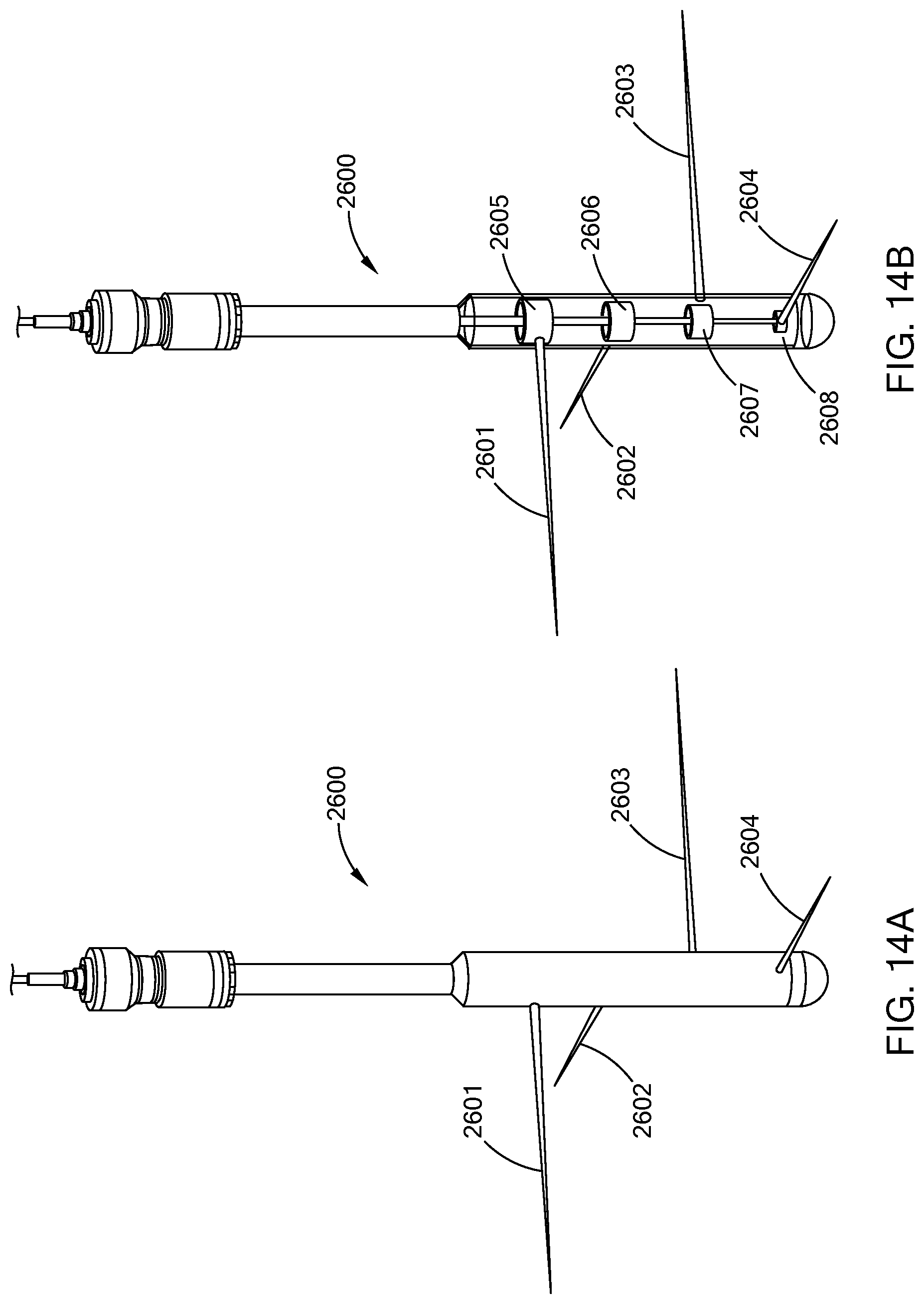
D00014

D00015

D00016

D00017
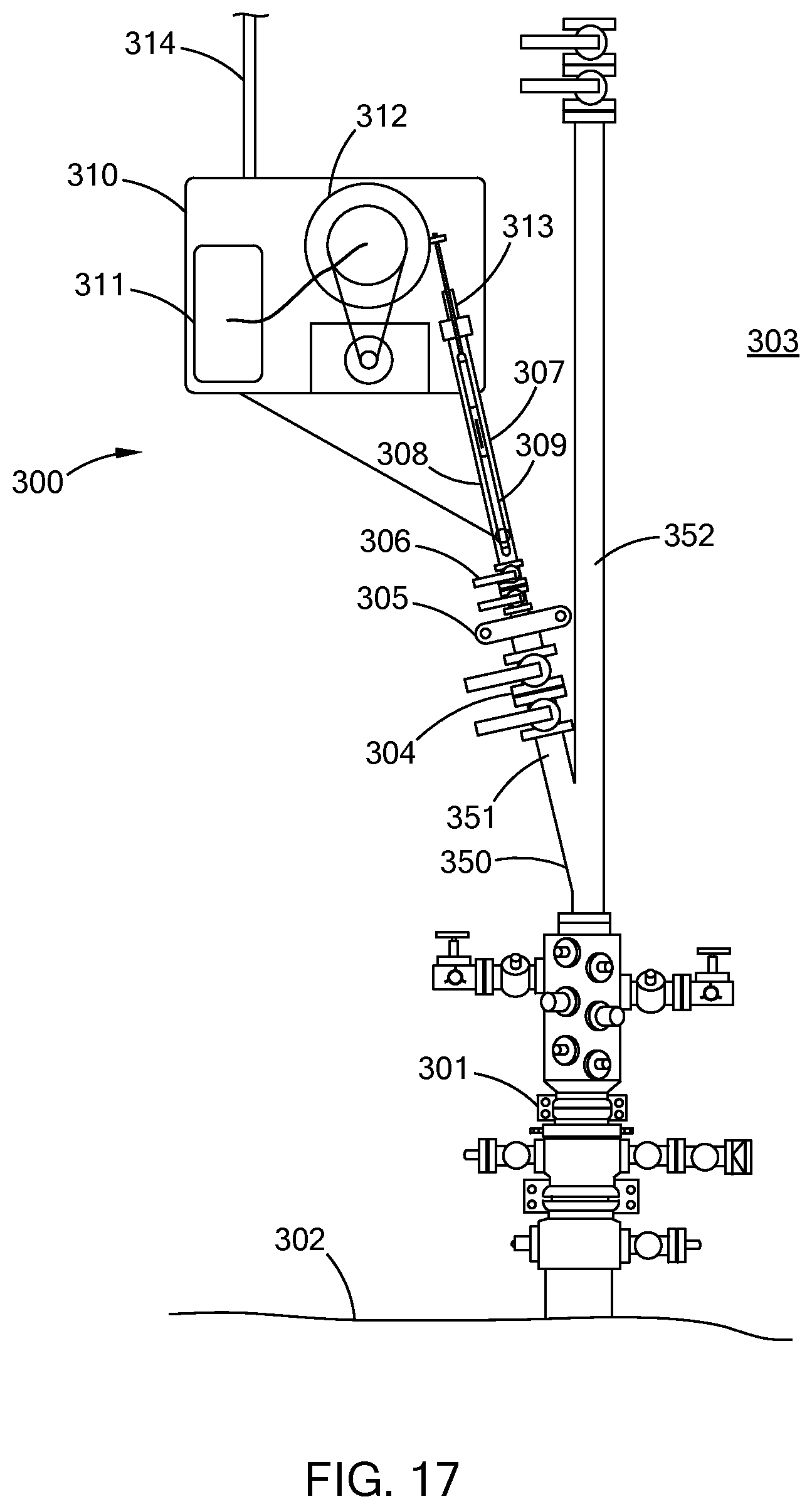
D00018
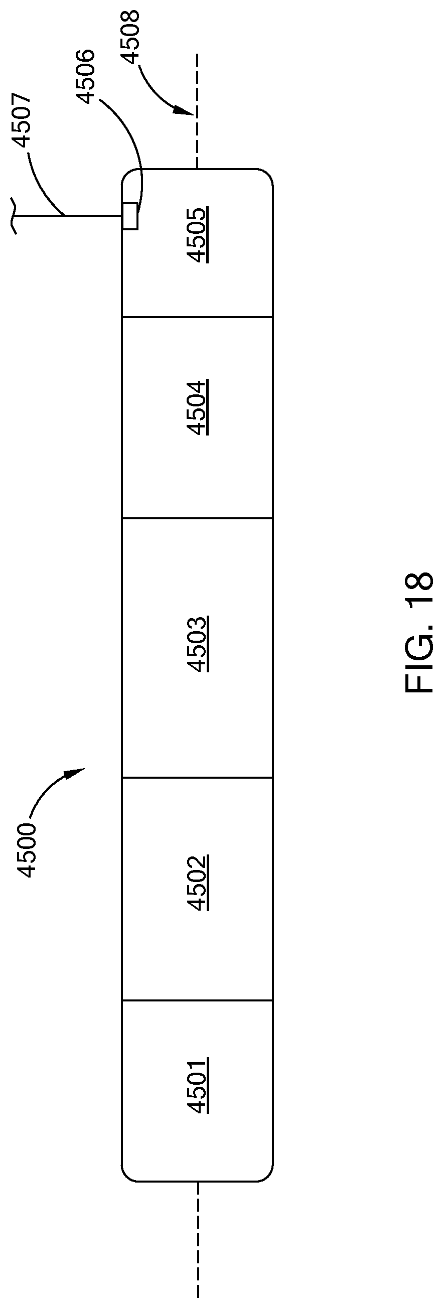
D00019

D00020

D00021
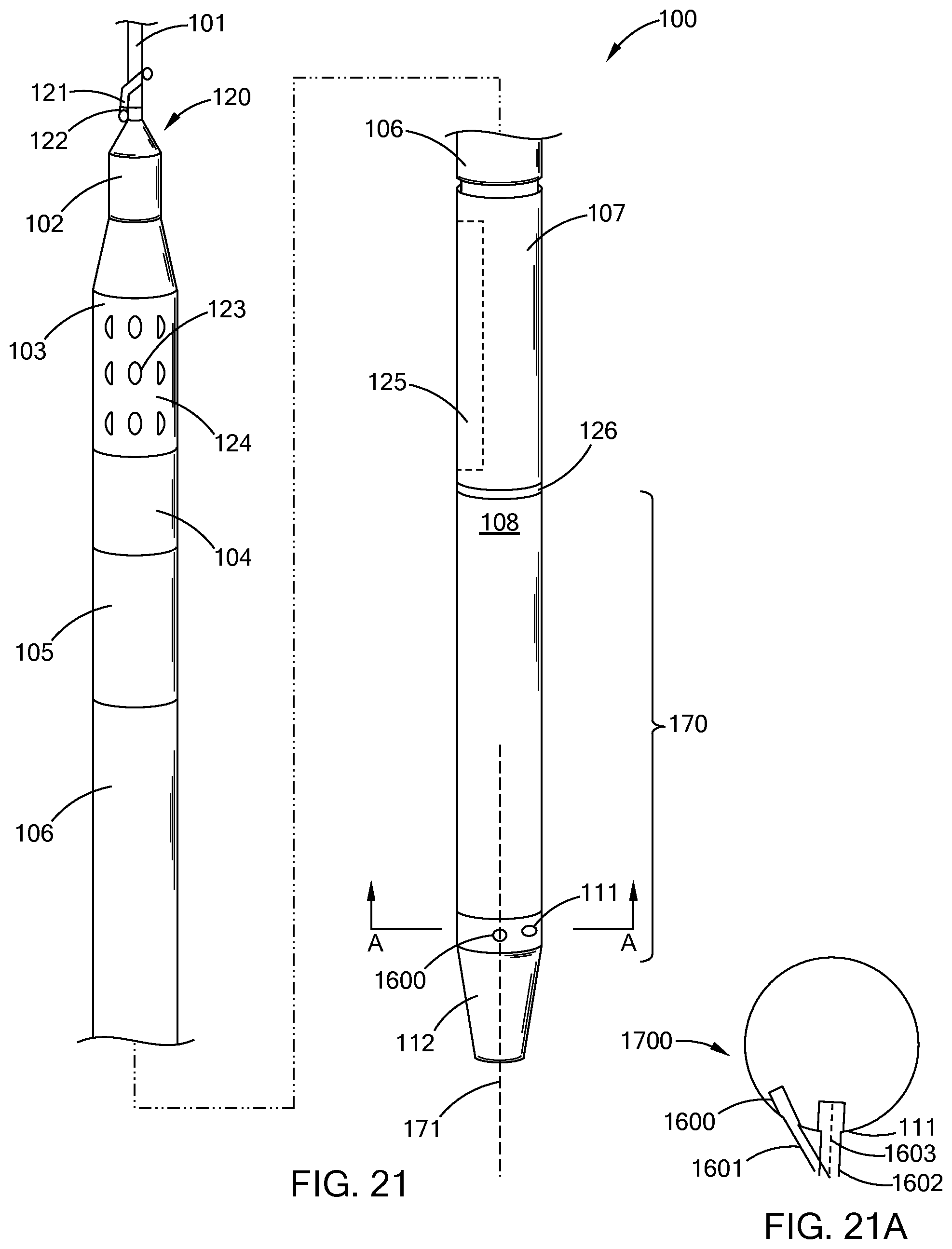
D00022

D00023

D00024
D00025

D00026

D00027

D00028

D00029

D00030
D00031

D00032

D00033

D00034

D00035

D00036
D00037

D00038

D00039
D00040

D00041
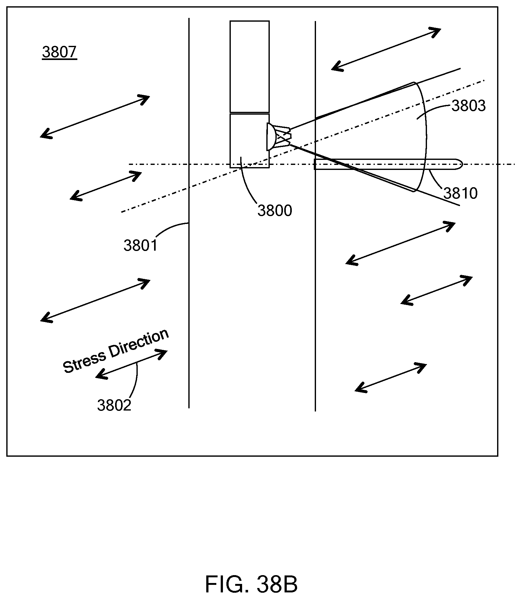
XML
uspto.report is an independent third-party trademark research tool that is not affiliated, endorsed, or sponsored by the United States Patent and Trademark Office (USPTO) or any other governmental organization. The information provided by uspto.report is based on publicly available data at the time of writing and is intended for informational purposes only.
While we strive to provide accurate and up-to-date information, we do not guarantee the accuracy, completeness, reliability, or suitability of the information displayed on this site. The use of this site is at your own risk. Any reliance you place on such information is therefore strictly at your own risk.
All official trademark data, including owner information, should be verified by visiting the official USPTO website at www.uspto.gov. This site is not intended to replace professional legal advice and should not be used as a substitute for consulting with a legal professional who is knowledgeable about trademark law.